

Page 1

EliteConnect™ Universal
2.4GHz/5GHz Wireless Dual-Band
Outdoor Access Point/Bridge
The easy way to make all your network connections
38 Tesla
Irvine, CA 92618
Phone: (949) 679-8000
May 2005
Revision Number: R01
F1.1.2.5
Page 2

Copyright
Information furnished by SMC Networks, Inc. (SMC) is believed to be accurate and reliable.
However, no responsibility is assumed by SMC for its use, nor for any infringements of patents
or other rights of third parties which may result from its use. No license is granted by
implication or otherwise under any patent or patent rights of SMC. SMC reserves the right to
change specifications at any time without notice.
Copyright © 2005 by
SMC Networks, Inc.
38 Tesla
Irvine, CA 92618
All rights reserved.
Trademarks:
SMC is a registered trademark; and EliteConnect is a trademark of SMC Networks, Inc. Other
product and company names are trademarks or registered trademarks of their respective
holders.
Page 3

LIMITED WARRANTY
Limited Warranty Statement: SMC Networks, Inc. (“SMC”) warrants its products
to be free from defects in workmanship and materials, under normal use and
service, for the applicable warranty term. All SMC products carry a standard
90-day limited warranty from the date of purchase from SMC or its Authorized
Reseller. SMC may, at its own discretion, repair or replace any product not
operating as warranted with a similar or functionally equivalent product, during the
applicable warranty term. SMC will endeavor to repair or replace any product
returned under warranty within 30 days of receipt of the product.
The standard limited warranty can be upgraded to a Limited Lifetime* warranty by
registering new products within 30 days of purchase from SMC or its Authorized
Reseller. Registration can be accomplished via the enclosed product registration
card or online via the SMC Web site. Failure to register will not affect the standard
limited warranty. The Limited Lifetime warranty covers a product during the Life of
that Product, which is defined as the period of time during which the product is an
“Active” SMC product. A product is considered to be “Active” while it is listed on
the current SMC price list. As new technologies emerge, older technologies
become obsolete and SMC will, at its discretion, replace an older product in its
product line with one that incorporates these newer technologies. At that point, the
obsolete product is discontinued and is no longer an “Active” SMC product. A list
of discontinued products with their respective dates of discontinuance can be
found at:
http://www.smc.com/index.cfm?action=customer_service_warranty.
All products that are replaced become the property of SMC. Replacement
products may be either new or reconditioned. Any replaced or repaired product
carries either a 30-day limited warranty or the remainder of the initial warranty,
whichever is longer. SMC is not responsible for any custom software or firmware,
configuration information, or memory data of Customer contained in, stored on, or
integrated with any products returned to SMC pursuant to any warranty. Products
returned to SMC should have any customer-installed accessory or add-on
components, such as expansion modules, removed prior to returning the product
for replacement. SMC is not responsible for these items if they are returned with
the product.
Customers must contact SMC for a Return Material Authorization number prior to
returning any product to SMC. Proof of purchase may be required. Any product
returned to SMC without a valid Return Material Authorization (RMA) number
clearly marked on the outside of the package will be returned to customer at
customer’s expense. For warranty claims within North America, please call our
toll-free customer support number at (800) 762-4968.
i
Page 4

LIMITED WARRANTY
Customers are responsible for all shipping charges from their facility to SMC. SMC
is responsible for return shipping charges from SMC to customer.
WARRANTIES EXCLUSIVE: IF AN SMC PRODUCT DOES NOT OPERATE AS
WARRANTED ABOVE, CUSTOMER’S SOLE REMEDY SHALL BE REPAIR OR
REPLACEMENT OF THE PRODUCT IN QUESTION, AT SMC’S OPTION. THE
FOREGOING WARRANTIES AND REMEDIES ARE EXCLUSIVE AND ARE IN
LIEU OF ALL OTHER WARRANTIES OR CONDITIONS, EXPRESS OR
IMPLIED, EITHER IN FACT OR BY OPERATION OF LAW, STATUTORY OR
OTHERWISE, INCLUDING WARRANTIES OR CONDITIONS OF
MERCHANTABILITY AND FITNESS FOR A PARTICULAR PURPOSE. SMC
NEITHER ASSUMES NOR AUTHORIZES ANY OTHER PERSON TO ASSUME
FOR IT ANY OTHER LIABILITY IN CONNECTION WITH THE SALE,
INSTALLATION, MAINTENANCE OR USE OF ITS PRODUCTS. SMC SHALL
NOT BE LIABLE UNDER THIS WARRANTY IF ITS TESTING AND
EXAMINATION DISCLOSE THE ALLEGED DEFECT IN THE PRODUCT DOES
NOT EXIST OR WAS CAUSED BY CUSTOMER’S OR ANY THIRD PERSON’S
MISUSE, NEGLECT, IMPROPER INSTALLATION OR TESTING,
UNAUTHORIZED ATTEMPTS TO REPAIR, OR ANY OTHER CAUSE BEYOND
THE RANGE OF THE INTENDED USE, OR BY ACCIDENT, FIRE, LIGHTNING,
OR OTHER HAZARD.
LIMITATION OF LIABILITY: IN NO EVENT, WHETHER BASED IN CONTRACT
OR TORT (INCLUDING NEGLIGENCE), SHALL SMC BE LIABLE FOR
INCIDENTAL, CONSEQUENTIAL, INDIRECT, SPECIAL, OR PUNITIVE
DAMAGES OF ANY KIND, OR FOR LOSS OF REVENUE, LOSS OF BUSINESS,
OR OTHER FINANCIAL LOSS ARISING OUT OF OR IN CONNECTION WITH
THE SALE, INSTALLATION, MAINTENANCE, USE, PERFORMANCE, FAILURE,
OR INTERRUPTION OF ITS PRODUCTS, EVEN IF SMC OR ITS AUTHORIZED
RESELLER HAS BEEN ADVISED OF THE POSSIBILITY OF SUCH DAMAGES.
SOME STATES DO NOT ALLOW THE EXCLUSION OF IMPLIED WARRANTIES
OR THE LIMITATION OF INCIDENTAL OR CONSEQUENTIAL DAMAGES FOR
CONSUMER PRODUCTS, SO THE ABOVE LIMITATIONS AND EXCLUSIONS
MAY NOT APPLY TO YOU. THIS WARRANTY GIVES YOU SPECIFIC LEGAL
RIGHTS, WHICH MAY VARY FROM STATE TO STATE. NOTHING IN THIS
WARRANTY SHALL BE TAKEN TO AFFECT YOUR STATUTORY RIGHTS.
* SMC will provide warranty service for one year following discontinuance from
the active SMC price list. Under the limited lifetime warranty, internal and
external power supplies, fans, and cables are covered by a standard one-year
warranty from date of purchase.
SMC Networks, Inc.
38 Tesla
Irvine, CA 92618
ii
Page 5

COMPLIANCES
Federal Communication Commission Interference
Statement
This equipment has been tested and found to comply with the limits for a Class B
digital device, pursuant to Part 15 of the FCC Rules. These limits are designed to
provide reasonable protection against harmful interference in a residential
installation. This equipment generates, uses and can radiate radio frequency
energy and, if not installed and used in accordance with the instructions, may
cause harmful interference to radio communications. However, there is no
guarantee that interference will not occur in a particular installation. If this
equipment does cause harmful interference to radio or television reception, which
can be determined by turning the equipment off and on, the user is encouraged to
try to correct the interference by one of the following measures:
• Reorient or relocate the receiving antenna
• Increase the separation between the equipment and receiver
• Connect the equipment into an outlet on a circuit different from that to which the
receiver is connected
• Consult the dealer or an experienced radio/TV technician for help
Warnings: 1.Wear an anti-static wrist strap or take other suitable measures to
2.When connecting this device to a power outlet, connect the field
FCC Caution: Any changes or modifications not expressly approved by the party
responsible for compliance could void the user's authority to operate this
equipment. This device complies with Part 15 of the FCC Rules. Operation is
subject to the following two conditions: (1) This device may not cause harmful
interference, and (2) this device must accept any interference received, including
interference that may cause undesired operation.
prevent electrostatic discharge when handling this equipment.
ground lead on the tri-pole power plug to a valid earth ground line to
prevent electrical hazards.
IMPORTANT NOTE:
FCC Radiation Exposure Statement
This equipment complies with FCC radiation exposure limits set forth for an
uncontrolled environment. This equipment should be installed and operated with a
minimum distance of 20 centimeters (8 inches) between the radiator and your
body. This transmitter must not be co-located or operating in conjunction with any
other antenna or transmitter.
iii
Page 6

COMPLIANCES
Wireless 5 GHz Band Statements:
As the SMC2888W access point/bridge can operate in the 5150-5250 MHz
frequency band it is limited by the FCC, Industry Canada and some other
countries to indoor use only so as to reduce the potential for harmful interference
to co-channel Mobile Satellite systems.
High power radars are allocated as primary users (meaning they have priority) of
the 5250-5350 MHz and 5650-5850 MHz bands. These radars could cause
interference and/or damage to the access point.
EC Conformance Declaration
SMC contact for these products in Europe is:
SMC Networks Europe,
Edificio Conata II,
Calle Fructuós Gelabert 6-8, 2
08970 - Sant Joan Despí,
Barcelona, Spain.
Marking by the above symbol indicates compliance with the Essential
Requirements of the R&TTE Directive of the European Union (1999/5/EC). This
equipment meets the following conformance standards:
• EN 60950 (IEC 60950) - Product Safety
• EN 301 893 - Technical requirements for 5 GHz radio equipment
• EN 300 328 - Technical requirements for 2.4 GHz radio equipment
• EN 301 489-1 / EN 301 489-17 - EMC requirements for radio equipment
o
, 4a,
0560
Countries of Operation & Conditions of Use in the European
Community
This device is intended to be operated in all countries of the European
Community. Requirements for indoor vs. outdoor operation, license requirements
and allowed channels of operation apply in some countries as described below:
Note: The user must use the configuration utility provided with this product to
ensure the channels of operation are in conformance with the spectrum
usage rules for European Community countries as described below.
• This device requires that the user or installer properly enter the current country
of operation in the command line interface as described in the user guide, before
operating this device.
• This device will automatically limit the allowable channels determined by the
current country of operation. Incorrectly entering the country of operation may
result in illegal operation and may cause harmful interference to other system.
The user is obligated to ensure the device is operating according to the channel
limitations, indoor/outdoor restrictions and license requirements for each
European Community country as described in this document.
iv
Page 7

C
OMPLIANCES
• This device employs a radar detection feature required for European Community
operation in the 5 GHz band. This feature is automatically enabled when the
country of operation is correctly configured for any European Community
country. The presence of nearby radar operation may result in temporary
interruption of operation of this device. The radar detection feature will
automatically restart operation on a channel free of radar.
• The 5 GHz Turbo Mode feature is not allowed for operation in any European
Community country. The current setting for this feature is found in the 5 GHz
802.11a Radio Settings Window as described in the user guide.
• The 5 GHz radio's Auto Channel Select setting described in the user guide must
always remain enabled to ensure that automatic 5 GHz channel selection
complies with European requirements. The current setting for this feature is
found in the 5 GHz 802.11a Radio Settings Window as described in the user
guide.
• This device is restricted to indoor use when operated in the European
Community using the 5.15 - 5.35 GHz band: Channels 36, 40, 44, 48, 52, 56, 60,
64. See table below for allowed 5 GHz channels by country.
• This device may be operated indoors or outdoors in all countries of the European
Community using the 2.4 GHz band: Channels 1 - 13, except where noted
below.
- In Italy the end-user must apply for a license from the national spectrum
authority to operate this device outdoors.
- In Belgium outdoor operation is only permitted using the 2.46 - 2.4835 GHz
band: Channel 13.
- In France outdoor operation is only permitted using the 2.4 - 2.454 GHz band:
Channels 1 - 7
v
Page 8

COMPLIANCES
Operation Using 5 GHz Channels in the European
Community
The user/installer must use the provided configuration utility to check the current
channel of operation and make necessary configuration changes to ensure
operation occurs in conformance with European National spectrum usage laws as
described below and elsewhere in this document.
Allowed 5GHz Channels in Each European Community Country
Allowed Frequency Bands Allowed Channel Numbers Countries
5.15 - 5.25 GHz* 36, 40, 44, 48 Austria, Belgium
5.15 - 5.35 GHz* 36, 40, 44, 48, 52, 56, 60, 64 France,
5.15 - 5.35* & 5.470 - 5.725
GHz
5 GHz Operation Not
Allowed
* Outdoor operation is not allowed using 5.15-5.35 GHz bands (Channels 36 - 64).
* Currently channels 36-64 are unavailable for use either indoors or outdoors.
36, 40, 44, 48, 52, 56, 60, 64,
100, 104, 108, 112, 116, 120,
124, 128, 132, 136, 140
None Greece
Switzerland,
Liechtenstein
Denmark, Finland,
Germany, Iceland,
Ireland, Italy,
Luxembourg,
Netherlands,
Norway, Portugal,
Spain, Sweden,
U.K.
vi
Page 9

C
OMPLIANCES
Declaration of Conformity in Languages of the European
Community
English Hereby, SMC Networks, declares that this Radio LAN device is in
Finnish Valmistaja SMC Networks vakuuttaa täten että Radio LAN device
Dutch Hierbij verklaart SMC Networks dat het toestel Radio LAN device
French Par la présente SMC Networks déclare que l'appareil Radio LAN
Swedish Härmed intygar SMC Networks att denna Radio LAN device står
Danish Undertegnede SMC Networks erklærer herved, at følgende udstyr
German Hiermit erklärt SMC Networks, dass sich dieser/diese/dieses
Greek Με την παρουσα SMC Networks δηλωνει οτι radio LAN device
compliance with the essential requirements and other relevant
provisions of Directive 1999/5/EC.
tyyppinen laite on direktiivin 1999/5/EY oleellisten vaatimusten ja
sitä koskevien direktiivin muiden ehtojen mukainen.
in overeenstemming is met de essentiële eisen en de andere
relevante bepalingen van richtlijn 1999/5/EG
Bij deze SMC Networks dat deze Radio LAN device voldoet aan
de essentiële eisen en aan de overige relevante bepalingen van
Richtlijn 1999/5/EC.
device est conforme aux exigences essentielles et aux autres
dispositions pertinentes de la directive 1999/5/CE
I överensstämmelse med de väsentliga egenskapskrav och
övriga relevanta bestämmelser som framgår av direktiv 1999/5/
EG.
Radio LAN device overholder de væsentlige krav og øvrige
relevante krav i direktiv 1999/5/EF
Radio LAN device in Übereinstimmung mit den grundlegenden
Anforderungen und den anderen relevanten Vorschriften der
Richtlinie 1999/5/EG befindet". (BMWi)
Hiermit erklärt SMC Networks die Übereinstimmung des Gerätes
Radio LAN device mit den grundlegenden Anforderungen und
den anderen relevanten Festlegungen der Richtlinie 1999/5/EG.
(Wien)
συµµορφωνεται προσ τισ ουσιωδεισ απαιτησεισ και τισ λοιπεσ
σΧετικεσ διαταξεισ τησ οδηγιασ 1999/5/εκ
vii
Page 10

COMPLIANCES
Italian Con la presente SMC Networks dichiara che questo Radio LAN
Spanish Por medio de la presente SMC Networks declara que el Radio
Portuguese SMC Networks declara que este Radio LAN device está conforme
device è conforme ai requisiti essenziali ed alle altre disposizioni
pertinenti stabilite dalla direttiva 1999/5/CE.
LAN device cumple con los requisitos esenciales y cualesquiera
otras disposiciones aplicables o exigibles de la Directiva 1999/5/
CE
com os requisitos essenciais e outras disposições da Directiva
1999/5/CE.
Safety Compliance
Power Cord Safety
Please read the following safety information carefully before installing the wireless
access point:
WARNING: Installation and removal of the unit must be carried out by qualified
personnel only.
• The unit must be connected to an earthed (grounded) outlet to comply with
international safety standards.
• Do not connect the unit to an A.C. outlet (power supply) without an earth
(ground) connection.
• The appliance coupler (the connector to the unit and not the wall plug) must have
a configuration for mating with an EN 60320/IEC 320 appliance inlet.
• The socket outlet must be near to the unit and easily accessible. You can only
remove power from the unit by disconnecting the power cord from the outlet.
• This unit operates under SELV (Safety Extra Low Voltage) conditions according
to IEC 60950. The conditions are only maintained if the equipment to which it is
connected also operates under SELV conditions.
France and Peru only
This unit cannot be powered from IT
unit must be powered by 230 V (2P+T) via an isolation transformer ratio 1:1, with
the secondary connection point labelled Neutral, connected directly to earth
(ground).
†
Impédance à la terre
†
supplies. If your supplies are of IT type, this
viii
Page 11

C
OMPLIANCES
Important! Before making connections, make sure you have the correct cord set.
Check it (read the label on the cable) against the following:
Power Cord Set
U.S.A. and
Canada
Denmark The supply plug must comply with Section 107-2-D1,
Switzerland The supply plug must comply with SEV/ASE 1011.
U.K. The supply plug must comply with BS1363 (3-pin 13 A) and
Europe The supply plug must comply with CEE7/7 (“SCHUKO”).
The cord set must be UL-approved and CSA certified.
The minimum specifications for the flexible cord are:
- No. 18 AWG - not longer than 2 meters, or 16 AWG.
- Type SV or SJ
- 3-conductor
The cord set must have a rated current capacity of at least
10 A
The attachment plug must be an earth-grounding type with
NEMA 5-15P (15 A, 125 V) or NEMA 6-15P (15 A, 250 V)
configuration.
Standard DK2-1a or DK2-5a.
be fitted with a 5 A fuse which complies with BS1362.
The mains cord must be <HAR> or <BASEC> marked and
be of type HO3VVF3GO.75 (minimum).
The mains cord must be <HAR> or <BASEC> marked and
be of type HO3VVF3GO.75 (minimum).
IEC-320 receptacle.
ix
Page 12

COMPLIANCES
Veuillez lire à fond l'information de la sécurité suivante avant
d'installer le wireless access point:
AVERTISSEMENT: L’installation et la dépose de ce groupe doivent être confiés à un
personnel qualifié.
• Ne branchez pas votre appareil sur une prise secteur (alimentation électrique)
lorsqu'il n'y a pas de connexion de mise à la terre (mise à la masse).
• Vous devez raccorder ce groupe à une sortie mise à la terre (mise à la masse) afin
de respecter les normes internationales de sécurité.
• Le coupleur d’appareil (le connecteur du groupe et non pas la prise murale) doit
respecter une configuration qui permet un branchement sur une entrée d’appareil
EN 60320/IEC 320.
• La prise secteur doit se trouver à proximité de l’appareil et son accès doit être
facile. Vous ne pouvez mettre l’appareil hors circuit qu’en débranchant son cordon
électrique au niveau de cette prise.
• L’appareil fonctionne à une tension extrêmement basse de sécurité qui est
conforme à la norme IEC 60950. Ces conditions ne sont maintenues que si
l’équipement auquel il est raccordé fonctionne dans les mêmes conditions.
France et Pérou uniquement:
Ce groupe ne peut pas être alimenté par un dispositif à impédance à la terre. Si vos
alimentations sont du type impédance à la terre, ce groupe doit être alimenté par
une tension de 230 V (2 P+T) par le biais d’un transformateur d’isolement à rapport
1:1, avec un point secondaire de connexion portant l’appellation Neutre et avec
raccordement direct à la terre (masse).
Cordon électrique - Il doit être agréé dans le pays d’utilisation
Etats-Unis et
Canada:
Danemark: La prise mâle d’alimentation doit respecter la section 107-2 D1 de la
Le cordon doit avoir reçu l’homologation des UL et un certificat de la CSA.
Les spe'cifications minimales pour un cable flexible sont AWG No. 18,
ouAWG No. 16 pour un cable de longueur infe'rieure a` 2 me'tres.
- type SV ou SJ
- 3 conducteurs
Le cordon doit être en mesure d’acheminer un courant no minal d’au moins
10 A.
La prise femelle de branchement doit être du type à mise à la terre (mise
à la masse) et respecter la configuration NEMA 5-15P (15 A, 125 V) ou
NEMA 6-15P (15 A, 250 V).
norme DK2 1a ou DK2 5a.
x
Page 13

C
OMPLIANCES
Cordon électrique - Il doit être agréé dans le pays d’utilisation
Suisse: La prise mâle d’alimentation doit respecter la norme SEV/ASE 1011.
Europe La prise secteur doit être conforme aux normes CEE 7/7 (“SCHUKO”)
LE cordon secteur doit porter la mention <HAR> ou <BASEC> et doit être
de type HO3VVF3GO.75 (minimum).
Bitte unbedingt vor dem Einbauen des Access Point die folgenden
Sicherheitsanweisungen durchlesen
WARNUNG: Die Installation und der Ausbau des Geräts darf nur durch
Fachpersonal erfolgen.
• Das Gerät sollte nicht an eine ungeerdete Wechselstromsteckdose
angeschlossen werden.
• Das Gerät muß an eine geerdete Steckdose angeschlossen werden, welche die
internationalen Sicherheitsnormen erfüllt.
• Der Gerätestecker (der Anschluß an das Gerät, nicht der
Wandsteckdosenstecker) muß einen gemäß EN 60320/IEC 320 konfigurierten
Geräteeingang haben.
• Die Netzsteckdose muß in der Nähe des Geräts und leicht zugänglich sein. Die
Stromversorgung des Geräts kann nur durch Herausziehen des
Gerätenetzkabels aus der Netzsteckdose unterbrochen werden.
• Der Betrieb dieses Geräts erfolgt unter den SELV-Bedingungen
(Sicherheitskleinstspannung) gemäß IEC 60950. Diese Bedingungen sind nur
(Germany):
xi
Page 14

COMPLIANCES
gegeben, wenn auch die an das Gerät angeschlossenen Geräte unter
•
SELV-Bedingungen betrieben werden.
Stromkabel. Dies muss von dem Land, in dem es benutzt wird geprüft werden:
U.S.A und
Kanada
Danemark Dieser Stromstecker muß die ebene 107-2-D1, der
Schweiz Dieser Stromstecker muß die SEV/ASE
Europe Das Netzkabel muß vom Typ HO3VVF3GO.75
Der Cord muß das UL gepruft und war das CSA
beglaubigt.
Das Minimum spezifikation fur der Cord sind:
- Nu. 18 AWG - nicht mehr als 2 meter, oder 16 AWG.
- Der typ SV oder SJ
- 3-Leiter
Der Cord muß haben eine strombelastbarkeit aus
wenigstens 10 A
Dieser Stromstecker muß hat einer erdschluss mit der typ
NEMA 5-15P (15A, 125V) oder NEMA 6-15P (15A, 250V)
konfiguration.
standard DK2-1a oder DK2-5a Bestimmungen einhalten.
1011Bestimmungen einhalten.
(Mindestanforderung) sein und die Aufschrift <HAR> oder
<BASEC> tragen.
Der Netzstecker muß die Norm CEE 7/7 erfüllen
(”SCHUKO”).
xii
Page 15

T
ABLE OF
C
ONTENTS
1 Introduction . . . . . . . . . . . . . . . . . . . . . . . . . . . . . 1-1
Package Checklist . . . . . . . . . . . . . . . . . . . . . . . . . . . . . . . . . 1-2
Hardware Description . . . . . . . . . . . . . . . . . . . . . . . . . . . . . . . 1-4
Integrated High-Gain Antenna . . . . . . . . . . . . . . . . . . . . . 1-5
External Antenna Options . . . . . . . . . . . . . . . . . . . . . . . . 1-5
Ethernet Port . . . . . . . . . . . . . . . . . . . . . . . . . . . . . . . . . . 1-5
Power Injector Module . . . . . . . . . . . . . . . . . . . . . . . . . . . 1-6
Receive Signal Strength Indicator (RSSI)
BNC Connector . . . . . . . . . . . . . . . . . . . . . . . . . . . . . 1-7
Grounding Point . . . . . . . . . . . . . . . . . . . . . . . . . . . . . . . . 1-7
Wall- and Pole-Mounting Bracket Kits . . . . . . . . . . . . . . . 1-7
System Configuration . . . . . . . . . . . . . . . . . . . . . . . . . . . . . . . 1-8
Features and Benefits . . . . . . . . . . . . . . . . . . . . . . . . . . . . . . 1-9
System Defaults . . . . . . . . . . . . . . . . . . . . . . . . . . . . . . . . . . 1-10
2 Network Configuration . . . . . . . . . . . . . . . . . . . . 2-1
Access Point Topologies . . . . . . . . . . . . . . . . . . . . . . . . . . . . 2-1
Ad Hoc Wireless LAN (no Access Point or Bridge) . . . . . 2-2
Infrastructure Wireless LAN . . . . . . . . . . . . . . . . . . . . . . . 2-3
Infrastructure Wireless LAN for Roaming Wireless PCs . 2-4
Bridge Link Topologies . . . . . . . . . . . . . . . . . . . . . . . . . . . . . . 2-5
Point-to-Point Configuration . . . . . . . . . . . . . . . . . . . . . . . 2-6
Point-to-Multipoint Configuration . . . . . . . . . . . . . . . . . . . 2-6
3 Bridge Link Planning . . . . . . . . . . . . . . . . . . . . . 3-1
Radio Path Planning . . . . . . . . . . . . . . . . . . . . . . . . . . . . . . . . 3-1
Antenna Height . . . . . . . . . . . . . . . . . . . . . . . . . . . . . . . . 3-3
Antenna Position and Orientation . . . . . . . . . . . . . . . . . . 3-5
Radio Interference . . . . . . . . . . . . . . . . . . . . . . . . . . . . . . 3-6
Weather Conditions . . . . . . . . . . . . . . . . . . . . . . . . . . . . . 3-7
Ethernet Cabling . . . . . . . . . . . . . . . . . . . . . . . . . . . . . . . . . . . 3-8
Grounding . . . . . . . . . . . . . . . . . . . . . . . . . . . . . . . . . . . . . . . . 3-8
4 Hardware Installation . . . . . . . . . . . . . . . . . . . . . 4-1
Testing Basic Link Operation . . . . . . . . . . . . . . . . . . . . . . . . . 4-2
Mount the Unit . . . . . . . . . . . . . . . . . . . . . . . . . . . . . . . . . . . . 4-2
Using the Pole-Mounting Bracket . . . . . . . . . . . . . . . . . . 4-2
Using the Wall-Mounting Bracket . . . . . . . . . . . . . . . . . . . 4-4
xiii
Page 16

T
ABLE OF CONTENTS
Connect External Antennas . . . . . . . . . . . . . . . . . . . . . . . . . . .4-5
Connect Cables to the Unit . . . . . . . . . . . . . . . . . . . . . . . . . . .4-7
Connect the Power Injector . . . . . . . . . . . . . . . . . . . . . . . . . . .4-7
Align Antennas . . . . . . . . . . . . . . . . . . . . . . . . . . . . . . . . . . . . .4-9
5 Initial Configuration . . . . . . . . . . . . . . . . . . . . . . . 5-1
Initial Setup through the CLI . . . . . . . . . . . . . . . . . . . . . . . . . .5-2
Initial Configuration Steps . . . . . . . . . . . . . . . . . . . . . . . . .5-2
Using the Web-based Management Setup Wizard . . . . . . . . .5-4
6 System Configuration . . . . . . . . . . . . . . . . . . . . . 6-1
Advanced Configuration . . . . . . . . . . . . . . . . . . . . . . . . . . . . .6-3
System Identification . . . . . . . . . . . . . . . . . . . . . . . . . . . . .6-4
TCP / IP Settings . . . . . . . . . . . . . . . . . . . . . . . . . . . . . . . .6-7
Radius . . . . . . . . . . . . . . . . . . . . . . . . . . . . . . . . . . . . . . .6-10
PPPoE Settings . . . . . . . . . . . . . . . . . . . . . . . . . . . . . . . .6-13
Authentication . . . . . . . . . . . . . . . . . . . . . . . . . . . . . . . . .6-16
Filter Control . . . . . . . . . . . . . . . . . . . . . . . . . . . . . . . . . .6-26
SNMP . . . . . . . . . . . . . . . . . . . . . . . . . . . . . . . . . . . . . . .6-30
Administration . . . . . . . . . . . . . . . . . . . . . . . . . . . . . . . . .6-33
System Log . . . . . . . . . . . . . . . . . . . . . . . . . . . . . . . . . . .6-38
Wireless Distribution System (WDS) . . . . . . . . . . . . . . . .6-43
Bridge . . . . . . . . . . . . . . . . . . . . . . . . . . . . . . . . . . . . . . .6-45
Spanning Tree Protocol (STP) . . . . . . . . . . . . . . . . . . . .6-47
RSSI . . . . . . . . . . . . . . . . . . . . . . . . . . . . . . . . . . . . . . . .6-54
Radio Interface . . . . . . . . . . . . . . . . . . . . . . . . . . . . . . . . . . .6-56
Radio Settings A (802.11a) . . . . . . . . . . . . . . . . . . . . . . .6-57
Radio Settings G (802.11g) . . . . . . . . . . . . . . . . . . . . . . .6-63
Security (Bridge Mode) . . . . . . . . . . . . . . . . . . . . . . . . . .6-66
Security (Access Point Mode) . . . . . . . . . . . . . . . . . . . . .6-72
Status Information . . . . . . . . . . . . . . . . . . . . . . . . . . . . . . . . .6-87
AP Status . . . . . . . . . . . . . . . . . . . . . . . . . . . . . . . . . . . .6-87
Station Status . . . . . . . . . . . . . . . . . . . . . . . . . . . . . . . . .6-90
Event Logs . . . . . . . . . . . . . . . . . . . . . . . . . . . . . . . . . . .6-92
7 Command Line Interface . . . . . . . . . . . . . . . . . . . 7-1
Using the Command Line Interface . . . . . . . . . . . . . . . . . . . . .7-1
Accessing the CLI . . . . . . . . . . . . . . . . . . . . . . . . . . . . . . .7-1
Telnet Connection . . . . . . . . . . . . . . . . . . . . . . . . . . . . . . .7-1
xiv
Page 17

T
ABLE OF CONTENTS
Entering Commands . . . . . . . . . . . . . . . . . . . . . . . . . . . . . . . . 7-3
Keywords and Arguments . . . . . . . . . . . . . . . . . . . . . . . . 7-3
Minimum Abbreviation . . . . . . . . . . . . . . . . . . . . . . . . . . . 7-3
Command Completion . . . . . . . . . . . . . . . . . . . . . . . . . . . 7-3
Getting Help on Commands . . . . . . . . . . . . . . . . . . . . . . . 7-4
Partial Keyword Lookup . . . . . . . . . . . . . . . . . . . . . . . . . . 7-5
Negating the Effect of Commands . . . . . . . . . . . . . . . . . . 7-5
Using Command History . . . . . . . . . . . . . . . . . . . . . . . . . 7-5
Understanding Command Modes . . . . . . . . . . . . . . . . . . 7-6
Exec Commands . . . . . . . . . . . . . . . . . . . . . . . . . . . . . . . 7-6
Configuration Commands . . . . . . . . . . . . . . . . . . . . . . . . 7-7
Command Line Processing . . . . . . . . . . . . . . . . . . . . . . . 7-8
Command Groups . . . . . . . . . . . . . . . . . . . . . . . . . . . . . . . . . 7-9
General Commands . . . . . . . . . . . . . . . . . . . . . . . . . . . . . . . 7-10
configure . . . . . . . . . . . . . . . . . . . . . . . . . . . . . . . . . . . . 7-10
end . . . . . . . . . . . . . . . . . . . . . . . . . . . . . . . . . . . . . . . . . 7-11
exit . . . . . . . . . . . . . . . . . . . . . . . . . . . . . . . . . . . . . . . . . 7-11
ping . . . . . . . . . . . . . . . . . . . . . . . . . . . . . . . . . . . . . . . . 7-12
reset . . . . . . . . . . . . . . . . . . . . . . . . . . . . . . . . . . . . . . . . 7-13
show history . . . . . . . . . . . . . . . . . . . . . . . . . . . . . . . . . . 7-14
show line . . . . . . . . . . . . . . . . . . . . . . . . . . . . . . . . . . . . 7-14
System Management Commands . . . . . . . . . . . . . . . . . . . . 7-15
country . . . . . . . . . . . . . . . . . . . . . . . . . . . . . . . . . . . . . . 7-16
prompt . . . . . . . . . . . . . . . . . . . . . . . . . . . . . . . . . . . . . . 7-18
system name . . . . . . . . . . . . . . . . . . . . . . . . . . . . . . . . . 7-19
username . . . . . . . . . . . . . . . . . . . . . . . . . . . . . . . . . . . . 7-19
password . . . . . . . . . . . . . . . . . . . . . . . . . . . . . . . . . . . . 7-20
ip http port . . . . . . . . . . . . . . . . . . . . . . . . . . . . . . . . . . . 7-20
ip http server . . . . . . . . . . . . . . . . . . . . . . . . . . . . . . . . . 7-21
show system . . . . . . . . . . . . . . . . . . . . . . . . . . . . . . . . . 7-22
show version . . . . . . . . . . . . . . . . . . . . . . . . . . . . . . . . . 7-23
System Logging Commands . . . . . . . . . . . . . . . . . . . . . . . . 7-23
logging on . . . . . . . . . . . . . . . . . . . . . . . . . . . . . . . . . . . 7-24
logging host . . . . . . . . . . . . . . . . . . . . . . . . . . . . . . . . . . 7-24
logging console . . . . . . . . . . . . . . . . . . . . . . . . . . . . . . . 7-25
logging level . . . . . . . . . . . . . . . . . . . . . . . . . . . . . . . . . . 7-25
logging facility-type . . . . . . . . . . . . . . . . . . . . . . . . . . . . 7-26
show logging . . . . . . . . . . . . . . . . . . . . . . . . . . . . . . . . . 7-27
xv
Page 18

T
ABLE OF CONTENTS
System Clock Commands . . . . . . . . . . . . . . . . . . . . . . . . . . .7-28
sntp-server ip . . . . . . . . . . . . . . . . . . . . . . . . . . . . . . . . . .7-29
sntp-server enable . . . . . . . . . . . . . . . . . . . . . . . . . . . . . .7-30
sntp-server date-time . . . . . . . . . . . . . . . . . . . . . . . . . . .7-31
sntp-server daylight-saving . . . . . . . . . . . . . . . . . . . . . . .7-31
sntp-server timezone . . . . . . . . . . . . . . . . . . . . . . . . . . . .7-32
show sntp . . . . . . . . . . . . . . . . . . . . . . . . . . . . . . . . . . . .7-33
SNMP Commands . . . . . . . . . . . . . . . . . . . . . . . . . . . . . . . . .7-34
snmp-server community . . . . . . . . . . . . . . . . . . . . . . . . .7-34
snmp-server contact . . . . . . . . . . . . . . . . . . . . . . . . . . . .7-35
snmp-server enable server . . . . . . . . . . . . . . . . . . . . . . .7-36
snmp-server host . . . . . . . . . . . . . . . . . . . . . . . . . . . . . .7-37
snmp-server location . . . . . . . . . . . . . . . . . . . . . . . . . . . .7-38
show snmp . . . . . . . . . . . . . . . . . . . . . . . . . . . . . . . . . . .7-39
Flash/File Commands . . . . . . . . . . . . . . . . . . . . . . . . . . . . . .7-39
bootfile . . . . . . . . . . . . . . . . . . . . . . . . . . . . . . . . . . . . . . .7-40
copy . . . . . . . . . . . . . . . . . . . . . . . . . . . . . . . . . . . . . . . .7-41
delete . . . . . . . . . . . . . . . . . . . . . . . . . . . . . . . . . . . . . . .7-42
dir . . . . . . . . . . . . . . . . . . . . . . . . . . . . . . . . . . . . . . . . . .7-43
RADIUS Client . . . . . . . . . . . . . . . . . . . . . . . . . . . . . . . . . . . .7-45
radius-server address . . . . . . . . . . . . . . . . . . . . . . . . . . .7-45
radius-server port . . . . . . . . . . . . . . . . . . . . . . . . . . . . . .7-46
radius-server key . . . . . . . . . . . . . . . . . . . . . . . . . . . . . . .7-47
radius-server retransmit . . . . . . . . . . . . . . . . . . . . . . . . .7-47
radius-server timeout . . . . . . . . . . . . . . . . . . . . . . . . . . . .7-48
show radius . . . . . . . . . . . . . . . . . . . . . . . . . . . . . . . . . . .7-48
Authentication . . . . . . . . . . . . . . . . . . . . . . . . . . . . . . . . . . . .7-49
802.1x . . . . . . . . . . . . . . . . . . . . . . . . . . . . . . . . . . . . . . .7-51
802.1x broadcast-key-refresh-rate . . . . . . . . . . . . . . . . .7-52
802.1x session-key-refresh-rate . . . . . . . . . . . . . . . . . . .7-53
802.1x session-timeout . . . . . . . . . . . . . . . . . . . . . . . . . .7-54
802.1x supplicant . . . . . . . . . . . . . . . . . . . . . . . . . . . . . .7-55
address filter default . . . . . . . . . . . . . . . . . . . . . . . . . . . .7-56
address filter entry . . . . . . . . . . . . . . . . . . . . . . . . . . . . . .7-57
address filter delete . . . . . . . . . . . . . . . . . . . . . . . . . . . . .7-58
mac-authentication server . . . . . . . . . . . . . . . . . . . . . . . .7-59
mac-authentication session-timeout . . . . . . . . . . . . . . . .7-60
show authentication . . . . . . . . . . . . . . . . . . . . . . . . . . . . .7-60
xvi
Page 19

T
ABLE OF CONTENTS
WDS Commands . . . . . . . . . . . . . . . . . . . . . . . . . . . . . . . . . 7-61
wds channel . . . . . . . . . . . . . . . . . . . . . . . . . . . . . . . . . . 7-62
wds mac-address . . . . . . . . . . . . . . . . . . . . . . . . . . . . . . 7-62
wds enable . . . . . . . . . . . . . . . . . . . . . . . . . . . . . . . . . . . 7-63
show wds . . . . . . . . . . . . . . . . . . . . . . . . . . . . . . . . . . . . 7-64
Bridge Commands . . . . . . . . . . . . . . . . . . . . . . . . . . . . . . . . 7-65
bridge timeout . . . . . . . . . . . . . . . . . . . . . . . . . . . . . . . . 7-66
bridge stp-bridge spanning-tree . . . . . . . . . . . . . . . . . . . 7-66
bridge stp-bridge forward-time . . . . . . . . . . . . . . . . . . . . 7-67
bridge stp-bridge hello-time . . . . . . . . . . . . . . . . . . . . . . 7-68
bridge stp-bridge max-age . . . . . . . . . . . . . . . . . . . . . . . 7-69
bridge stp-bridge priority . . . . . . . . . . . . . . . . . . . . . . . . 7-70
bridge stp-port path-cost . . . . . . . . . . . . . . . . . . . . . . . . 7-71
bridge stp-port priority . . . . . . . . . . . . . . . . . . . . . . . . . . 7-72
bridge stp-port portfast . . . . . . . . . . . . . . . . . . . . . . . . . . 7-73
bridge stp-port spanning-disabled . . . . . . . . . . . . . . . . . 7-74
show bridge . . . . . . . . . . . . . . . . . . . . . . . . . . . . . . . . . . 7-75
Filtering Commands . . . . . . . . . . . . . . . . . . . . . . . . . . . . . . . 7-76
filter local-bridge . . . . . . . . . . . . . . . . . . . . . . . . . . . . . . . 7-76
filter ap-manage . . . . . . . . . . . . . . . . . . . . . . . . . . . . . . . 7-77
filter ethernet-type enable . . . . . . . . . . . . . . . . . . . . . . . 7-78
filter ethernet-type protocol . . . . . . . . . . . . . . . . . . . . . . 7-79
show filters . . . . . . . . . . . . . . . . . . . . . . . . . . . . . . . . . . . 7-80
PPPoE Commands . . . . . . . . . . . . . . . . . . . . . . . . . . . . . . . . 7-80
ip pppoe . . . . . . . . . . . . . . . . . . . . . . . . . . . . . . . . . . . . . 7-81
pppoe ip allocation mode . . . . . . . . . . . . . . . . . . . . . . . . 7-82
pppoe ipcp dns . . . . . . . . . . . . . . . . . . . . . . . . . . . . . . . . 7-83
pppoe lcp echo-interval . . . . . . . . . . . . . . . . . . . . . . . . . 7-84
pppoe lcp echo-failure . . . . . . . . . . . . . . . . . . . . . . . . . . 7-85
pppoe local ip . . . . . . . . . . . . . . . . . . . . . . . . . . . . . . . . . 7-86
pppoe remote ip . . . . . . . . . . . . . . . . . . . . . . . . . . . . . . . 7-86
pppoe username . . . . . . . . . . . . . . . . . . . . . . . . . . . . . . 7-87
pppoe password . . . . . . . . . . . . . . . . . . . . . . . . . . . . . . . 7-88
pppoe service-name . . . . . . . . . . . . . . . . . . . . . . . . . . . 7-89
pppoe restart . . . . . . . . . . . . . . . . . . . . . . . . . . . . . . . . . 7-89
show pppoe . . . . . . . . . . . . . . . . . . . . . . . . . . . . . . . . . . 7-90
Ethernet Interface Commands . . . . . . . . . . . . . . . . . . . . . . . 7-91
interface ethernet . . . . . . . . . . . . . . . . . . . . . . . . . . . . . . 7-91
xvii
Page 20

T
ABLE OF CONTENTS
dns server . . . . . . . . . . . . . . . . . . . . . . . . . . . . . . . . . . . .7-92
ip address . . . . . . . . . . . . . . . . . . . . . . . . . . . . . . . . . . . .7-93
ip dhcp . . . . . . . . . . . . . . . . . . . . . . . . . . . . . . . . . . . . . . .7-94
shutdown . . . . . . . . . . . . . . . . . . . . . . . . . . . . . . . . . . . . .7-95
show interface ethernet . . . . . . . . . . . . . . . . . . . . . . . . . .7-96
Wireless Interface Commands . . . . . . . . . . . . . . . . . . . . . . . .7-97
interface wireless . . . . . . . . . . . . . . . . . . . . . . . . . . . . . . .7-99
description . . . . . . . . . . . . . . . . . . . . . . . . . . . . . . . . . . . .7-99
ssid . . . . . . . . . . . . . . . . . . . . . . . . . . . . . . . . . . . . . . . .7-100
closed-system . . . . . . . . . . . . . . . . . . . . . . . . . . . . . . . .7-101
speed . . . . . . . . . . . . . . . . . . . . . . . . . . . . . . . . . . . . . .7-101
channel . . . . . . . . . . . . . . . . . . . . . . . . . . . . . . . . . . . . .7-102
turbo . . . . . . . . . . . . . . . . . . . . . . . . . . . . . . . . . . . . . . .7-103
beacon-interval . . . . . . . . . . . . . . . . . . . . . . . . . . . . . . .7-104
dtim-period . . . . . . . . . . . . . . . . . . . . . . . . . . . . . . . . . .7-104
fragmentation-length . . . . . . . . . . . . . . . . . . . . . . . . . . .7-105
rts-threshold . . . . . . . . . . . . . . . . . . . . . . . . . . . . . . . . .7-106
transmit-power . . . . . . . . . . . . . . . . . . . . . . . . . . . . . . . .7-107
max-association . . . . . . . . . . . . . . . . . . . . . . . . . . . . . .7-108
authentication . . . . . . . . . . . . . . . . . . . . . . . . . . . . . . . .7-109
encryption . . . . . . . . . . . . . . . . . . . . . . . . . . . . . . . . . . .7-110
key . . . . . . . . . . . . . . . . . . . . . . . . . . . . . . . . . . . . . . . . .7-112
transmit-key . . . . . . . . . . . . . . . . . . . . . . . . . . . . . . . . . .7-113
multicast-cipher . . . . . . . . . . . . . . . . . . . . . . . . . . . . . . .7-114
wpa-clients . . . . . . . . . . . . . . . . . . . . . . . . . . . . . . . . . .7-116
wpa-mode . . . . . . . . . . . . . . . . . . . . . . . . . . . . . . . . . . .7-117
wpa-preshared-key . . . . . . . . . . . . . . . . . . . . . . . . . . . .7-118
wpa-psk-type . . . . . . . . . . . . . . . . . . . . . . . . . . . . . . . . .7-119
shutdown . . . . . . . . . . . . . . . . . . . . . . . . . . . . . . . . . . . .7-120
show interface wireless . . . . . . . . . . . . . . . . . . . . . . . . .7-120
show station . . . . . . . . . . . . . . . . . . . . . . . . . . . . . . . . .7-121
IAPP Commands . . . . . . . . . . . . . . . . . . . . . . . . . . . . . . . . .7-122
iapp . . . . . . . . . . . . . . . . . . . . . . . . . . . . . . . . . . . . . . . .7-122
VLAN Commands . . . . . . . . . . . . . . . . . . . . . . . . . . . . . . . .7-123
vlan . . . . . . . . . . . . . . . . . . . . . . . . . . . . . . . . . . . . . . . .7-124
native-vlanid . . . . . . . . . . . . . . . . . . . . . . . . . . . . . . . . .7-125
xviii
Page 21

T
ABLE OF CONTENTS
A Troubleshooting . . . . . . . . . . . . . . . . . . . . . . . . . A-1
B Specifications . . . . . . . . . . . . . . . . . . . . . . . . . . . B-1
General Specifications . . . . . . . . . . . . . . . . . . . . . . . . . . . . . . B-1
Antenna Specifications . . . . . . . . . . . . . . . . . . . . . . . . . . . . . . B-4
17 dBi Integrated Panel . . . . . . . . . . . . . . . . . . . . . . . . . . B-4
C Cables and Pinouts . . . . . . . . . . . . . . . . . . . . . . . C-1
Twisted-Pair Cable Assignments . . . . . . . . . . . . . . . . . . . . . . C-1
10/100BASE-TX Pin Assignments . . . . . . . . . . . . . . . . . . C-2
Straight-Through Wiring . . . . . . . . . . . . . . . . . . . . . . . . . . C-3
Crossover Wiring . . . . . . . . . . . . . . . . . . . . . . . . . . . . . . . C-3
8-Pin DIN Connector Pinout . . . . . . . . . . . . . . . . . . . . . . . . . . C-4
8-Pin DIN to RJ-45 Cable Wiring . . . . . . . . . . . . . . . . . . . C-5
Glossary
Index
xix
Page 22

T
ABLE OF CONTENTS
xx
Page 23

Chapter 1
Introduction
The SMC EliteConnect Universal 2.4GHz/5GHz Wireless
Dual-Band Outdoor Access Point/Bridge system consists of two
models that provide point-to-point or point-to-multipoint bridge
links between remote Ethernet LANs, and wireless access point
services for clients in the local LAN area:
• SMC2888W-S – Includes an integrated high-gain antenna for
the 802.11a radio and is designed to operate as a “Slave”
bridge in point-to-multipoint configurations, or provide a
high-speed point-to-point wireless link between two sites. The
802.11b/g radio requires an external antenna option.
• SMC2888W-M – Provides only external antenna options and
is designed to operate as the “Master” bridge in
point-to-multipoint configurations, supporting wireless bridge
connections to as many as 16 SMC2888W-S Slave units.
Each model is housed in a weatherproof enclosure for mounting
outdoors and includes its own brackets for attaching to a wall,
pole, radio mast, or tower structure. The unit is powered through
its Ethernet cable connection from a power injector module that is
installed indoors.
The wireless bridge system offers a fast, reliable, and
cost-effective solution for connectivity between remote Ethernet
wired LANs or to provide Internet access to an isolated site. The
system is also easy to install and operate, ideal for situations
where a wired link may be difficult or expensive to deploy. The
wireless bridge connection provides data rates of up to 108
Mbps.
1-1
Page 24

Introduction
In addition, both wireless bridge models offer full network
management capabilities through an easy-to-use web interface, a
command-line interface, and support for Simple Network
Management Protocol (SNMP) tools.
Radio Characteristics – The IEEE 802.11a and 802.11g
standards use a radio modulation technique known as
Orthogonal Frequency Division Multiplexing (OFDM), and a
shared collision domain (CSMA/CA). The 802.11a standard
operates in the 5 GHz Unlicensed National Information
Infrastructure (UNII) band, and the 802.11g standard in the 2.4
GHz band.
IEEE 802.11g includes backward compatibility with the IEEE
802.11b standard. IEEE 802.11b also operates at 2.4 GHz, but
uses Direct Sequence Spread Spectrum (DSSS) and
Complementary Code Keying (CCK) modulation technology to
achieve a communication rate of up to 11 Mbps.
The wireless bridge provides a 54 Mbps half-duplex connection
for each active channel (up to 108 Mbps in turbo mode on the
802.11a interface).
Package Checklist
The Dual-band Outdoor Access Point / Bridge package includes:
• One EliteConnect Universal 2.4GHz/5GHz Wireless
Dual-Band Outdoor Access Point/Bridge (SMC2888W-S or
SMC2888W-M)
• One Category 5 network cable, length 164 ft (50 m)
• One power injector module and power cord
1-2
Page 25

Package Checklist
• Outdoor pole-mounting bracket kit
• Outdoor wall-mounting bracket kit
• This User Guide
Inform your dealer if there are any incorrect, missing or damaged
parts. If possible, retain the carton, including the original packing
materials. Use them again to repack the product in case there is a
need to return it.
1-3
Page 26
Introduction
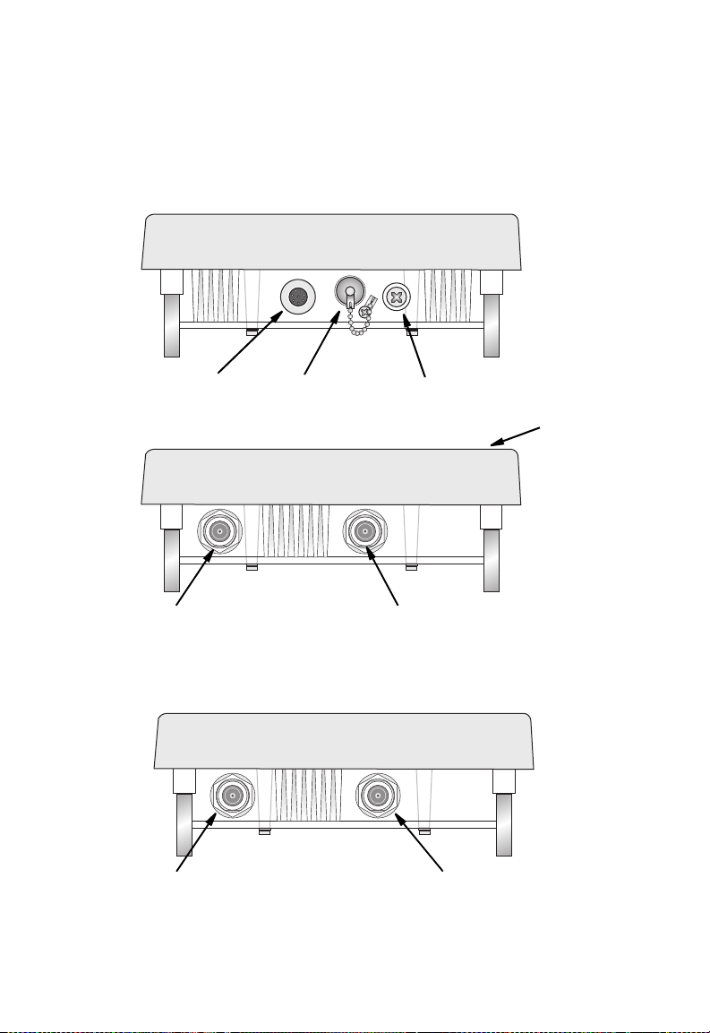
Hardware Description
Bottom View
Ethernet Port
Top View (SMC2888W-S)
N-Type External
Antenna Connector
(2.4 GHz)
Top View (SMC2888W-M)
N-Type External
Antenna Connector
(2.4 GHz)
RSSI Connector with
Protective Cap
Grounding Point
Screw
N-Type External
Antenna Connector
(2.4 GHz)
N-Type External
Antenna Connector
(5 GHz)
Integrated Antenna
1-4
Page 27

Hardware Description
Integrated High-Gain Antenna
The SMC2888W-S wireless bridge includes an integrated
high-gain (17 dBi) flat-panel antenna for 5 GHz operation.
External Antenna Options
The SMC2888W-M Master bridge unit does not include an
integrated antenna, but provides various external antenna options
for both 5 GHz and 2.4 GHz operation. In a point-to-multipoint
configuration, an external high-gain omnidirectional, sector, or
high-gain panel antenna can be attached to communicate with
bridges spread over a wide area.
External antennas connect to the N-type RF connectors on the
wireless bridge using the provided coaxial cables.
Ethernet Port
The wireless bridge has one 10BASE-T/100BASE-TX 8-pin DIN
port that connects to the power injector module using the
included Ethernet cable. The Ethernet port connection provides
power to the wireless bridge as well as a data link to the local
network.
The wireless bridge appears as an Ethernet node and performs a
bridging function by moving packets from the wired LAN to the
remote end of the wireless bridge link.
Note: The power injector module does not support Power over Ethernet
(PoE) based on the IEEE 802.3af standard. The wireless bridge
unit must always be powered on by being connected to the power
injector module.
1-5
Page 28

Introduction
Power Injector Module
The wireless bridge receives power through its network cable
connection using power-over-Ethernet technology. A power
injector module is included in the wireless bridge package and
provides two RJ-45 Ethernet ports, one for connecting to the
wireless bridge (Output), and the other for connecting to a local
LAN switch (Input).
The Input port uses an MDI (i.e., internal straight-through) pin
configuration. You can therefore use straight-through twisted-pair
cable to connect this port to most network interconnection
devices such as a switch or router that provide MDI-X ports.
However, when connecting the access point to a workstation or
other device that does not have MDI-X ports, you must use
crossover twisted-pair cable.
Ethernet from
Local Network
LED Indicator
Input Output
Ethernet and Power to
Wireless Bridge
AC Power Socket
(Hidden)
The wireless bridge does not have a power switch. It is powered
on when its Ethernet port is connected to the power injector
module, and the power injector module is connected to an AC
power source. The power injector includes one LED indicator that
turns on when AC power is applied.
1-6
Page 29

Hardware Description
The power injector module automatically adjusts to any AC
voltage between 100-240 volts at 50 or 60 Hz. No voltage range
settings are required.
Warning: The power injector module is designed for indoor use only.
Never mount the power injector outside with the wireless
bridge unit.
Receive Signal Strength Indicator (RSSI) BNC Connector
The RSSI connector provides an output voltage that is
proportional to the received radio signal strength. A DC voltmeter
can be connected this port to assist in aligning the antennas at
both ends of a wireless bridge link.
Grounding Point
Even though the wireless bridge includes its own built-in lightning
protection, it is important that the unit is properly connected to
ground. A grounding screw is provided for attaching a ground wire
to the unit.
Wall- and Pole-Mounting Bracket Kits
The wireless bridge includes bracket kits that can be used to
mount the bridge to a wall, pole, radio mast, or part of a tower
structure.
1-7
Page 30

Introduction
System Configuration
At each location where a unit is installed, it must be connected to
the local network using the power injector module. The following
figure illustrates the system component connections.
External Antenna
LAN Switch
Indoor Outdoor
Ethernet Cable Ethernet Cable
Power
Injector
AC Power
RF Coaxial Cable
Wireless Bridge Unit
Ground Wire
1-8
Page 31

Features and Benefits
Features and Benefits
• SMC2888W-S Slave units support a 5 GHz high-gain 17 dBi
antenna
• SMC2888W-M Master units support 5 GHz point-to-multipoint
links using various external antenna options
• Both SMC2888W-S and SMC2888W-M units also support
access point services for the 5 GHz and 2.4 GHz radios using
various external antenna options
• Maximum data rate up to 108 Mbps on the 802.11a (5 GHz)
radio
• Outdoor weatherproof design
• IEEE 802.11a and 802.11b/g compliant
• Local network connection via 10/100 Mbps Ethernet port
• Powered through its Ethernet cable connection to the power
injector module
• Includes wall- and pole-mount brackets
• Security through 64/128/152-bit Wired Equivalent Protection
(WEP) or 128-bit Advanced Encryption Standard (AES)
encryption, and WiFi Protected Areas (WPA)
• Scans all available channels and selects the best channel and
data rate based on the signal-to-noise ratio
• Manageable through an easy-to-use web-browser interface,
command line (via Telnet), or SNMP network management
tools
1-9
Page 32

Introduction
System Defaults
The following table lists some of the wireless bridge’s basic
system defaults. To reset the bridge defaults, use the CLI
command “reset configuration” from the Exec level prompt.
Feature Parameter Default
Identification System Name Dual Band Outdoor
Administration User Name admin
Password smcadmin
General HTTP Server Enabled
HTTP Server Port 80
TCP/IP IP Address DHCP
Subnet Mask 255.255.255.0
Default Gateway 0.0.0.0
Primary DNS IP 0.0.0.0
Secondary DNS IP 0.0.0.0
VLANs Status Disabled
Native VLAN ID 1
Filter Control Ethernet Type Disabled
AP
1-10
Page 33

System Defaults
Feature Parameter Default
SNMP Status Enabled
Location null
Contact Contact
Community (Read Only) Public
Community (Read/Write) Private
Traps Enabled
Trap Destination IP Address null
Trap Destination Community
Name
System Logging Syslog Disabled
Logging Host Disabled
Logging Console Disabled
IP Address / Host Name 0.0.0.0
Logging Level Informational
Logging Facility Type 16
Spanning Tree Status Enabled
Ethernet
Interface
WDS Bridging Outdoor Bridge Band A (802.11a)
Speed and Duplex Auto
Public
1-11
Page 34

Introduction
Feature Parameter Default
Wireless
Interface
802.11a
Wireless
Security
802.11a
Status Enabled
SSID SMC
Turbo Mode Disabled
Radio Channel Default to first
Auto Channel Select Enabled
Transmit Power Full
Maximum Data Rate 54 Mbps
Beacon Interval 100 TUs
Data Beacon Rate (DTIM
Interval)
RTS Threshold 2347 bytes
Authentication Type Open System
AES Encryption Disabled
WEP Encryption Disabled
WEP Key Length 128 bits
WEP Key Type Hexadecimal
WEP Transmit Key Number 1
WEP Keys null
channel
2 beacons
1-12
Page 35

System Defaults
Feature Parameter Default
Wireless
Interface
802.11b/g
Wireless
Security
802.11b/g
Status Enabled
SSID SMC
Radio Channel Default to first
channel
Auto Channel Select Enabled
Transmit Power Full
Maximum Data Rate 54 Mbps
Beacon Interval 100 TUs
Data Beacon Rate (DTIM
Interval)
RTS Threshold 2347 bytes
Authentication Type Open System
AES Encryption Disabled
WEP Encryption Disabled
WEP Key Length 128 bits
WEP Key Type Hexadecimal
WEP Transmit Key Number 1
WEP Keys null
2 beacons
1-13
Page 36

Introduction
1-14
Page 37

Chapter 2
Network Configuration
The Dual-band Outdoor Access Point / Bridge system provides
access point or bridging services through either the 5 GHz or 2.4
GHz radio interfaces.
The wireless bridge units can be used just as normal 802.11a/b/g
access points connected to a local wired LAN, providing
connectivity and roaming services for wireless clients in an
outdoor area. Units can also be used purely as bridges
connecting remote LANs. Alternatively, you can employ both
access point and bridging functions together, offering a flexible
and convenient wireless solution for many applications.
This chapter describes the role of wireless bridge in various
wireless network configurations.
Access Point Topologies
Wireless networks support a stand-alone wireless configuration
as well as an integrated configuration with 10/100 Mbps Ethernet
LANs.
Wireless network cards, adapters, and access points can be
configured as:
• Ad hoc for departmental, SOHO, or enterprise LANs
• Infrastructure for wireless LANs
• Infrastructure wireless LAN for roaming wireless PCs
2-1
Page 38

Network Configuration
The 802.11b and 802.11g frequency band, which operates at
2.4 GHz, can easily encounter interference from other 2.4 GHz
devices, such as other 802.11b or g wireless devices, cordless
phones and microwave ovens. If you experience poor wireless
LAN performance, try the following measures:
• Limit any possible sources of radio interference within the
service area
• Increase the distance between neighboring access points
• Increase the channel separation of neighboring access points
(e.g., up to 3 channels of separation for 802.11b or up to 5
channels for 802.11g)
Ad Hoc Wireless LAN (no Access Point or Bridge)
An ad hoc wireless LAN consists of a group of computers, each
equipped with a wireless adapter, connected through radio
signals as an independent wireless LAN. Computers in a specific
ad hoc wireless LAN must therefore be configured to the same
radio channel.
2-2
Notebook with
Wireless USB Adapter
PC with Wireless
PCI Adapter
Ad Hoc Wireless LAN
Notebook with
Wireless PC Card
Page 39

Access Point Topologies
Infrastructure Wireless LAN
The access point function of the wireless bridge provides access
to a wired LAN for 802.11a/b/g wireless workstations. An
integrated wired/wireless LAN is called an Infrastructure
configuration. A Basic Service Set (BSS) consists of a group of
wireless PC users and an access point that is directly connected
to the wired LAN. Each wireless PC in a BSS can connect to any
computer in its wireless group or access other computers or
network resources in the wired LAN infrastructure through the
access point.
The infrastructure configuration not only extends the accessibility
of wireless PCs to the wired LAN, but also increases the effective
wireless transmission range for wireless PCs by passing their
signals through one or more access points.
A wireless infrastructure can be used for access to a central
database, or for connection between mobile workers, as shown in
the following figure.
Desktop PC
Wired LAN Extension
to Wireless Clients
Server
Switch
PC with Wireless
PCI Adapter
Notebook with Wireless
PC Card Adapter
Access Point
2-3
Page 40

Network Configuration
Infrastructure Wireless LAN for Roaming Wireless PCs
The Basic Service Set (BSS) defines the communications domain
for each access point and its associated wireless clients. The
BSS ID is a 48-bit binary number based on the access point’s
wireless MAC address, and is set automatically and transparently
as clients associate with the access point. The BSS ID is used in
frames sent between the access point and its clients to identify
traffic in the service area.
The BSS ID is only set by the access point, never by its clients.
The clients only need to set the Service Set Identifier (SSID) that
identifies the service set provided by one or more access points.
The SSID can be manually configured by the clients, can be
detected in an access point’s beacon, or can be obtained by
querying for the identity of the nearest access point. For clients
that do not need to roam, set the SSID for the wireless card to
that used by the access point to which you want to connect.
A wireless infrastructure can also support roaming for mobile
workers. More than one access point can be configured to create
an Extended Service Set (ESS). By placing the access points so
that a continuous coverage area is created, wireless users within
this ESS can roam freely. All wireless network card adapters and
wireless access points within a specific ESS must be configured
with the same SSID.
2-4
Page 41

Desktop PC
Seamless Roaming
for Wireless Clients
Server
Switch
Bridge Link Topologies
Notebook with Wireless
PC Card Adapter
PC with Wireless
PCI Adapter
Switch
Access Point
Notebook with Wireless
PC Card Adapter
<BSS1>
Access Point
<BSS2>
<ESS>
Bridge Link Topologies
The IEEE 802.11 standard defines a WIreless Distribution
System (WDS) for bridge connections between BSS areas
(access points). The outdoor wireless bridge uses WDS to
forward traffic on links between units. Up to 16 WDS links can be
specified for a SMC2888W-M unit, which acts as the “Master” in
the wireless bridge network. SMC2888W-S Slave units support
only one WDS link, which must be to the network’s master unit.
The SMC2888W-M and SMC2888W-S support WDS bridge links
on either the 5 GHz (802.11a) or 2.4 GHz (802.11b/g) bands and
can be used with various external antennas to offer flexible
deployment options.
2-5
Page 42

Network Configuration
Note: The external antennas offer longer range options using the 5 GHz
radio, which makes this interface more suitable for bridge links.
When using WDS on a radio band, only wireless bridge units can
associate to each other. Wireless clients can only associate with
the wireless bridge using a radio band set to access point mode.
Point-to-Point Configuration
Two SMC2888W-S bridges can form a wireless point-to-point link
using their 5 GHz (802.11a) integrated antennas.
SMC2888W-S
LAN
SMC2888W-S
Point-to-Multipoint Configuration
A SMC2888W-M wireless bridge can use an omnidirectional or
sector antenna to connect to as many as 16 bridges in a
point-to-multipoint configuration. There can only be one
SMC2888W-M “Master” unit in the wireless bridge network, all
other bridges must be SMC2888W-S “Slave” units.
LAN
2-6
Page 43

Bridge Link Topologies
Slave
Slave
Slave
Master with
Sector Antenna
Master with
Omnidirectional
Antenna
Slave
Slave
Slave
Slave
Slave
Slave
2-7
Page 44

Network Configuration
2-8
Page 45

Chapter 3
Bridge Link Planning
The SMC Dual-band Outdoor Access Point / Bridge supports
fixed point-to-point or point-to-multipoint wireless links. A single
link between two points can be used to connect a remote site to
larger core network. Multiple bridge links can provide a way to
connect widespread Ethernet LANs.
For each link in a wireless bridge network to be reliable and
provide optimum performance, some careful site planning is
required. This chapter provides guidance and information for
planning your wireless bridge links.
Note: The planning and installation of the wireless bridge requires
professional personnel that are trained in the installation of radio
transmitting equipment. The user is responsible for compliance
with local regulations concerning items such as antenna power,
use of lightning arrestors, grounding, and radio mast or tower
construction. Therefore, it is recommended to consult a
professional contractor knowledgeable in local radio regulations
prior to equipment installation.
Radio Path Planning
Although the wireless bridge uses IEEE 802.11a radio
technology, which is capable of reducing the effect of multipath
signals due to obstructions, the wireless bridge link requires a
“radio line-of-sight” between the two antennas for optimum
performance.
The concept of radio line-of-sight involves the area along a radio
link path through which the bulk of the radio signal power travels.
3-1
Page 46

Bridge Link Planning
This area is known as the first Fresnel Zone of the radio link. For
a radio link not to be affected by obstacles along its path, no
object, including the ground, must intrude within 60% of the first
Fresnel Zone.
The following figure illustrates the concept of a good radio
line-of-sight.
Visual Line of Sight
Radio Line of Sight
If there are obstacles in the radio path, there may still be a radio
link but the quality and strength of the signal will be affected.
Calculating the maximum clearance from objects on a path is
important as it directly affects the decision on antenna placement
and height. It is especially critical for long-distance links, where
the radio signal could easily be lost.
When planning the radio path for a wireless bridge link, consider
these factors:
• Avoid any partial line-of-sight between the antennas.
• Be cautious of trees or other foliage that may be near the path,
or may grow and obstruct the path.
3-2
Page 47

Radio Path Planning
• Be sure there is enough clearance from buildings and that no
building construction may eventually block the path.
• Check the topology of the land between the antennas using
topographical maps, aerial photos, or even satellite image
data (software packages are available that may include this
information for your area).
• Avoid a path that may incur temporary blockage due to the
movement of cars, trains, or aircraft.
Antenna Height
A reliable wireless link is usually best achieved by mounting the
antennas at each end high enough for a clear radio line of sight
between them. The minimum height required depends on the
distance of the link, obstacles that may be in the path, topology of
the terrain, and the curvature of the earth (for links over 3 miles).
For long-distance links, a mast or pole may need to be
contsructed to attain the minimum required height. Use the
following table to estimate the required minimum clearance above
the ground or path obstruction (for 5 GHz bridge links).
3-3
Page 48

Bridge Link Planning
.
Total Link
Distance
0.25 mile (402 m) 4.5 ft (1.4 m) 0 4.5 ft (1.4 m)
0.5 mile (805 m) 6.4 ft (1.95 m) 0 6.4 ft (1.95 m)
1 mile (1.6 km) 9 ft (2.7 m) 0 9 ft (2.7 m)
2 miles (3.2 km) 12.7 ft (3.9 m) 0 12.7 ft (3.9 m)
3 miles (4.8 km) 15.6 ft (4.8 m) 1.8 ft (0.5 m) 17.4 ft (5.3 m)
4 miles (6.4 km) 18 ft (5.5 m) 3.2 ft (1.0 m) 21.2 ft (6.5 m)
5 miles (8 km) 20 ft (6.1 m) 5 ft (1.5 m) 25 ft (7.6 m)
7 miles (11.3 km) 24 ft (7.3 m) 9.8 ft (3.0 m) 33.8 ft (10.3 m)
9 miles (14.5 km) 27 ft (8.2 m) 16 ft (4.9 m) 43 ft (13.1 m)
12 miles (19.3 km) 31 ft (9.5 m) 29 ft (8.8 m) 60 ft (18.3 m)
15 miles (24.1 km) 35 ft (10.7 m) 45 ft (13.7 m) 80 ft (24.4 m)
17 miles (27.4 km) 37 ft (11.3 m) 58 ft (17.7 m) 95 ft (29 m)
Note that to avoid any obstruction along the path, the height of
the object must be added to the minimum clearance required for a
clear radio line-of-sight. Consider the following simple example,
illustrated in the figure below.
Max Clearance
for 60% of First
Fresnel Zone at
5.8 GHz
Approximate
Clearance for
Earth
Curvature
Total
Clearance
Required at
Mid-point of
Link
2.4 m
20 m
3-4
A
Visual Line of Sight
3miles(4.8km)
17 m
5.4 m
Radio Line of Sight
B
1.4 m
9m
12 m
Page 49

Radio Path Planning
A wireless bridge link is deployed to connect building A to a
building B, which is located three miles (4.8 km) away. Mid-way
between the two buidings is a small tree-covered hill. From the
above table it can be seen that for a three-mile link, the object
clearance required at the mid-point is 5.3 m (17.4 ft). The
tree-tops on the hill are at an elevation of 17 m (56 ft), so the
antennas at each end of the link need to be at least 22.3 m (73 ft)
high. Building A is six stories high, or 20 m (66 ft), so a 2.3 m
(7.5 ft) mast or pole must be contructed on its roof to achieve the
required antenna height. Building B is only three stories high, or 9
m (30 ft), but is located at an elevation that is 12 m (39 ft) higher
than bulding A. To mount an anntena at the required height on
building B, a mast or pole of only 1.3 m (4.3 ft) is needed.
Warning: Never construct a radio mast, pole, or tower near overhead
power lines.
Note: Local regulations may limit or prevent construction of a high radio
mast or tower. If your wireless bridge link requires a high radio
mast or tower, consult a professional contractor for advice.
Antenna Position and Orientation
Once the required antenna height has been determined, other
factors affecting the precise position of the wireless bridge must
be considered:
• Be sure there are no other radio antennas within 2 m (6 ft) of
the wireless bridge
• Place the wireless bridge away from power and telephone
lines
• Avoid placing the wireless bridge too close to any metallic
reflective surfaces, such as roof-installed air-conditioning
equipment, tinted windows, wire fences, or water pipes
3-5
Page 50

Bridge Link Planning
• The wireless bridge antennas at both ends of the link must be
positioned with the same polarization direction, either
horizontal or vertical
Antenna Polarization — The wireless bridge’s integrated
antenna sends a radio signal that is polarized in a particular
direction. The antenna’s receive sensitivity is also higher for radio
signals that have the same polarization. To maximize the
performance of the wireless link, both antennas must be set to
the same polarization direction. The antenna polarization is
marked on the wireless bridge, as indicated in the following
figure.
V
H
Radio Interference
The avoidance of radio interference is an important part of
wireless link planning. Interference is caused by other radio
transmissions using the same or an adjacent channel frequency.
You should first scan your proposed site using a spectrum
analyzer to determine if there are any strong radio signals using
the 802.11a channel frequencies. Always use a channel
frequency that is furthest away from another signal.
If radio interference is still a problem with your wireless bridge
link, changing the antenna polarization direction may improve the
situation.
3-6
Page 51

Radio Path Planning
Weather Conditions
When planning wireless bridge links, you must take into account
any extreme weather conditions that are known to affect your
location. Consider these factors:
• Temperature — The wireless bridge is tested for normal
operation in temperatures from -33°C to 55°C. Operating in
temperatures outside of this range may cause the unit to fail.
• Wind Velocity — The wireless bridge can operate in winds up
to 90 MPH and survive higher wind speeds up to 125 MPH.
You must consider the known maximum wind velocity and
direction at the site and be sure that any supporting structure,
such as a pole, mast, or tower, is built to withstand this force.
• Lightning — The wireless bridge includes its own built-in
lightning protection. However, you should make sure that the
unit, any supporting structure, and cables are all properly
grounded. Additional protection using lightning rods, lightning
arrestors, or surge suppressors may also be employed.
• Rain — The wireless bridge is weatherproofed against rain.
Also, prolonged heavy rain has no significant effect on the
radio signal. However, it is recommended to apply
weatherproof sealing tape around the Ethernet port and
antenna connectors for extra protection. If moisture enters a
connector, it may cause a degradation in performance or even
a complete failure of the link.
• Snow and Ice — Falling snow, like rain, has no significant
effect on the radio signal. However, a build up of snow or ice
on antennas may cause the link to fail. In this case, the snow
or ice has to be cleared from the antennas to restore operation
of the link.
3-7
Page 52

Bridge Link Planning
Ethernet Cabling
When a suitable antenna location has been determined, you must
plan a cable route form the wireless bridge outdoors to the power
injector module indoors. Consider these points:
• The Ethernet cable length should never be longer than 100 m
(328 ft)
• Determine a building entry point for the cable
• Determine if conduits, bracing, or other structures are
required for safety or protection of the cable
• For lightning protection at the power injector end of the cable,
consider using a lightning arrestor immediately before the
cable enters the building
Grounding
It is important that the wireless bridge, cables, and any
supporting structures are properly grounded. The wireless bridge
unit includes a grounding screw for attaching a ground wire. Be
sure that grounding is available and that it meets local and
national electrical codes.
3-8
Page 53

Chapter 4
Hardware Installation
Before mounting antennas to set up your wireless bridge links, be
sure you have selected appropriate locations for each antenna.
Follow the guidance and information in Chapter 2, “Wireless Link
Planning.”
Also, before mounting units in their intended locations, you should
first perform initial configuration and test the basic operation of
the wireless bridge links in a controlled environment over a very
short range. (See the section “Testing Basic Link Operation” in
this chapter.)
The wireless bridge includes its own bracket kit for mounting the
unit to a 1.5 to 2 inch diameter steel pole or tube. The
pole-mounting bracket allows the unit to be mounted to part of a
radio mast or tower structure. The unit also has a wall-mounting
bracket kit that enables it to be fixed to a building wall or roof
when using external antennas.
Hardware installation of the wireless bridge involves these steps:
1. Mount the unit on a wall, pole, mast, or tower using the
mounting bracket.
2. Mount external antennas on the same supporting structure
as the bridge and connect them to the bridge unit.
3. Connect the Ethernet cable and a grounding wire to the unit.
4. Connect the power injector to the Ethernet cable, a local LAN
switch, and an AC power source.
4-1
Page 54

Hardware Installation
5. Align antennas at both ends of the link.
Testing Basic Link Operation
Set up the units over a very short range (15 to 25 feet), either
outdoors or indoors. Connect the units as indicated in this chapter
and be sure to perform all the basic configuration tasks outlined
above. When you are satisfied that the links are operating
correctly, proceed to mount the units in their intended locations.
Mount the Unit
Using the Pole-Mounting Bracket
Perform the following steps to mount the unit to a 1.5 to 2 inch
diameter steel pole or tube using the mounting bracket:
1. Always attach the bracket to a pole with the open end of the
mounting grooves facing up.
2. Place the U-shaped part of the bracket around the pole and
tighten the securing nut just enough to hold the bracket to the
pole. (The bracket may need to be rotated around the pole
during the alignment process.)
4-2
Page 55

Mount the Unit
Attach bracket to
pole with mounting
grooves facing up
3. Use the included nuts to tightly secure the wireless bridge to
the bracket. Be sure to take account of the antenna
polarization direction; both antennas in a link must be
mounted with the same polarization.
Antenna Polarization
Direction
4-3
Page 56

Hardware Installation
Mounting on Larger Diameter Poles
In addition, there is a method for attaching the pole-mounting
bracket to a pole that is 2 to 5 inches in diameter using an
adjustable steel band clamp (not included in the kit). A steel band
clamp up to 0.5 inch (1.27 cm) wide can be threaded through the
main part of the bracket to secure it to a larger diameter pole
without using the U-shaped part of the bracket. This method is
illustrated in the following figure.
Steel Band Clamp
Using the Wall-Mounting Bracket
Perform the following steps to mount the unit to a wall using the
wall-mounting bracket:
Note: The wall-mounting bracket does not allow the wireless bridge’s
intrgrated antenna to be aligned. It is intended for use with the
unit using an external antenna.
1. Always attach the bracket to a wall with the open end of the
mounting grooves facing up (see following figure).
4-4
Page 57

Connect External Antennas
Mounting Grooves
2. Position the bracket in the intended location and mark the
position of the three mounting screw holes.
3. Drill three holes in the wall that match the screws and wall
plugs included in the bracket kit, then secure the bracket to
the wall.
4. Use the included nuts to tightly secure the wireless bridge to
the bracket.
Connect External Antennas
When deploying a SMC2888W-M Master bridge unit for a bridge
link or access point operation, you need to mount external
antennas and connect them to the bridge. Typically, a bridge link
requires a 5 GHz antenna, and access point operation a 2.4 GHz
antenna. SMC2888W-S Slave units also require an external
antenna for 2.4 GHz operation.
Perform these steps:
1. Mount the external antenna to the same supporting structure
as the bridge, within 3 m (10 ft) distance, using the bracket
supplied in the antenna package.
4-5
Page 58

Hardware Installation
2. Connect the antenna to the bridge’s N-type connector.
3. Apply weatherproofing tape to the antenna connectors to
help prevent water entering the connectors.
SMC2888W-M
2.4 GHz
N-type Connector
5 GHz
N-type Connector
RF Coaxial Cable
5 GHz External
High-gain Panel
Antenna
2.4 GHz External
Omnidirectional
Antenna
4-6
Page 59

Connect Cables to the Unit
Connect Cables to the Unit
1. Attach the Ethernet cable to the Ethernet port on the wireless
bridge.
Note: The Ethernet cable included with the package is 30 m (100 ft)
long. To wire a longer cable (maximum 100 m, 325 ft), use the
connector pinout information in Appendix B.
2. For extra protection against rain or moisture, apply
weatherproofing tape (not included) around the Ethernet
connector.
3. Be sure to ground the unit with an appropriate grounding wire
(not included) by attaching it to the grounding screw on the
unit.
Caution: Be sure that grounding is available and that it meets local and
national electrical codes. For additional lightning protection,
use lightning rods, lightning arrestors, or surge suppressors.
Ethernet Cable
Ground Wire
Connect the Power Injector
To connect the wireless bridge to a power source:
Caution: Do not install the power injector outdoors. The unit is for
indoor installation only.
4-7
Page 60

Hardware Installation
Note: The wireless bridge’s Ethernet port does not support Power over
Ethernet (PoE) based on the IEEE 802.3af standard. Do not try to
power the unit by connecting it directly to a network switch that
provides IEEE 802.3af PoE. Always connect the unit to the
included power injector module.
1. Connect the Ethernet cable from the wireless bridge to the
RJ-45 port labeled “Output” on the power injector.
2. Connect a straight-through unshielded twisted-pair (UTP)
cable from a local LAN switch to the RJ-45 port labeled
“Input” on the power injector. Use Category 5 or better UTP
cable for 10/100BASE-TX connections.
Note: The RJ-45 port on the power injector is an MDI port. If connecting
directly to a computer for testing the link, use a crossover cable.
Ethernet cable
from LAN switch
Input
Output
Power LED indicator
AC power
Ethernet cable to
wireless bridge
3. Insert the power cable plug directly into the standard AC
receptacle on the power injector.
4. Plug the other end of the power cable into a grounded, 3-pin
socket, AC power source.
Note: For International use, you may need to change the AC line cord.
You must use a line cord set that has been approved for the
receptacle type in your country.
4-8
Page 61

Align Antennas
5. Check the LED on top of the power injector to be sure that
power is being supplied to the wireless bridge through the
Ethernet connection.
Align Antennas
After wireless bridge units have been mounted, connected, and
their radios are operating, the antennas must be accurately
aligned to ensure optimum performance on the bridge links. This
alignment process is particularly important for long-range
point-to-point links. In a point-to-multipoint configuration the
Master bridge uses an omnidirectional or sector antenna, which
does not require alignment, but Slave bridges still need to be
correctly aligned with the Master bridge antennna.
• Point-to-Point Configurations – In a point-to-point
configuration, the alignment process requires two people at
each end of the link. The use of cell phones or two-way radio
communication may help with coordination. To start, you can
just point the antennas at each other, using binoculars or a
compass to set the general direction. For accurate alignment,
you must connect a DC voltmeter to the RSSI connector on
the wireless bridge and monitor the voltage as the antenna
moves horizontally and vertically.
• Point-to-Multipoint Configurations – In a point-to-multipoint
configuration all Slave bridges must be aligned with the
Master bridge antenna. The alignment process is the same as
in point-to-point links, but only the Slave end of the link
requires the alignment.
The RSSI connector provides an output voltage between 0 and
3.28 VDC that is proportional to the received radio signal
strength. The higher the voltage reading, the stronger the signal.
The radio signal from the remote antenna can be seen to have a
4-9
Page 62

Hardware Installation
strong central main lobe and smaller side lobes. The object of the
alignment process is to set the antenna so that it is receiving the
strongest signal from the central main lobe.
Vertical Scan
Remote
Antenna
Horizontal Scan
RSSI
Voltage
Main Lobe
Maximum
Maximum Signal Strength Position
for Horizontal Alignment
RSSI Voltage
Side Lobe
Maximum
Maximum Signal
Strength Position for
Vertical Alignment
To align the antennas in the link using the RSSI output voltage,
start with one antenna fixed and then perform the following
procedure on the other antenna:
Note: The RSSI output can be configured through management
interfaces to output a value for specific WDS ports. See page
6-54 for more information.
1. Remove the RSSI connector cover and connect a voltmeter
using a cable with a male BNC connector (not included).
4-10
Page 63

Align Antennas
RSSI BNC
Connection
Voltmeter
2. Pan the antenna horizontally back and forth while checking
the RSSI voltage. If using the pole-mounting bracket with the
unit, you must rotate the mounting bracket around the pole.
Other external antenna brackets may require a different
horizontal adjustment.
3. Find the point where the signal is strongest (highest voltage)
and secure the horizontal adjustment in that position.
Note: Sometimes there may not be a central lobe peak in the voltage
because vertical alignment is too far off; only two similar peaks for
the side lobes are detected. In this case, fix the antenna so that it
is halfway between the two peaks.
4. Loosen the vertical adjustment on the mounting bracket and
tilt the antenna slowly up and down while checking the RSSI
voltage.
5. Find the point where the signal is strongest and secure the
vertical adjustment in that position.
6. Remove the voltmeter cable and replace the RSSI connector
cover.
4-11
Page 64

Hardware Installation
4-12
Page 65

Chapter 5
Initial Configuration
The wireless bridge offers a variety of management options,
including a web-based interface, a command line interface (CLI),
or using SNMP management software.
Most initial configuration steps can be made through the web
browser interface using the Setup Wizard (page 5-4). However,
for units that do not have a preset country code, you must first set
the country code using the CLI.
Note: Units sold in some countries are not configured with a specific
country code. You must use the CLI to set the country code and
enable wireless operation (page 5-2).
The wireless bridge requests an IP address via DHCP by default.
If no response is received from a DHCP server, then the wireless
bridge uses the default address 192.168.2.2. If this address is not
compatible with your network, you can first perform initial
configuration using a PC that has IP settings compatible with this
subnet (for example, 192.168.2.3) and connecting it directly to the
wireless bridge. When the basic configuration is completed, you
can set new IP settings for the wireless bridge before connecting
it to your network.
5-1
Page 66

Initial Configuration
Initial Setup through the CLI
The wireless bridge provides access to the CLI through a Telnet
connection. You can open a Telnet session by performing these
steps:
1. From the host computer, enter the Telnet command and the IP
address of the wireless bridge unit (default 192.168.2.2 if not
set via DHCP).
2. At the prompt, enter “admin” for the user name.
3. The default password is “smcadmin”.
The CLI will display the “Dual Outdoor#” prompt to show that you
are using executive access mode (i.e., Exec).
Username: admin
Password:
Dual Outdoor#
For a full description of how to use the CLI, see “Using the
Command Line Interface” on page 7-1. For a list of all the CLI
commands and detailed information on using the CLI, refer to
“Command Groups” on page 7-9.
Initial Configuration Steps
Setting the Country Code – Regulations for wireless products
differ from country to country. Setting the country code restricts
the wireless bridge to use only the radio channels and power
settings permitted in the specified country of operation. If the
wireless bridge unit is shipped with a preset country code, you
are not permitted to change it, as required by country regulations.
If the unit is set to the default “99,” you must set the country code
to the country of operation.
5-2
Page 67

Initial Setup through the CLI
At the Exec prompt, type “country ?” to display the list of country
codes. Check the code for your country, then enter the country
command again followed by your country code (e.g., IE for
Ireland).
Dual Outdoor#country ie
Dual Outdoor#
Setting the IP Address – By default, the wireless bridge is
configured to obtain IP address settings from a DHCP server. You
may also use the CLI to assign an IP address that is compatible
with your network.
Type “configure” to enter configuration mode, then type “interface
ethernet” to access the Ethernet interface-configuration mode.
Dual Outdoor#configure
Dual Outdoor(config)#interface ethernet
Dual Outdoor(config-if)#
First type “no ip dhcp” to disable DHCP client mode. Then type “ip
address ip-address netmask gateway,” where “ip-address” is the
wireless bridge’s IP address, “netmask” is the network mask for
the network, and “gateway” is the default gateway router. Check
with your system administrator to obtain an IP address that is
compatible with your network.
Dual Outdoor(if-ethernet)#no ip dhcp
Dual Outdoor(if-ethernet)#ip address 192.168.2.2 255.255.255.0
192.168.2.254
Dual Outdoor(if-ethernet)#
5-3
Page 68

Initial Configuration
After configuring the wireless bridge’s IP parameters, you can
access the management interface from anywhere within the
attached network. The command line interface can also be
accessed using Telnet from any computer attached to the
network.
Using the Web-based Management Setup Wizard
There are only a few basic steps you need to complete to set up
the wireless bridge for your network. The Setup Wizard takes you
through configuration procedures for the radio channel selection,
IP configuration, and basic WEP encryption for wireless security.
The wireless bridge can be managed by any computer using a
web browser (Internet Explorer 5.0 or above, or Netscape
Navigator 6.2 or above). Enter the IP configured for the unit or the
default IP address: http://192.168.2.2
Logging In – Enter the default username “admin” and password
“smcadmin” click LOGIN. For information on configuring a user
name and password, refer to page 6-33.
5-4
Page 69

Using the Web-based Management Setup Wizard
The home page displays the Main Menu.
Launching the Setup Wizard – To perform initial configuration,
click Setup Wizard on the home page, then click on the [Next]
button to start the process.
1. Service Set ID – Enter the service set identifier in the SSID
box which all wireless 802.11g clients must use to associate
with the access point. The SSID is case sensitive and can
consist of up to 32 alphanumeric characters (Default: SMC).
5-5
Page 70

Initial Configuration
2. Radio Channel – You must enable radio communications for
the 802.11a and 802.11g radios and set the operating
channel.
5-6
• 802.11a
Page 71

Using the Web-based Management Setup Wizard
Turbo Mode – If you select Enable, the wireless bridge
will operate in turbo mode with a data rate of up to 108
Mbps. Normal mode supports 13 channels, Turbo mode
supports only 5 channels. (Default: Disable)
802.11a Radio Channel – Set the operating radio
channel number. (Default: 56ch, 5.280 GHz)
Auto Channel Select – Select Enable to automatically
select an unoccupied radio channel. (Default: Enable)
• 802.11b/g
802.11g Radio Channel: Set the operating radio channel
number. (Range 1-11; Default: 1)
5-7
Page 72

Initial Configuration
Note: Available channel settings are limited by local regulations which
determine which channels are available.
3. IP Configuration – Either enable or disable (Dynamic Host
Configuration Protocol (DHCP) for automatic IP configuration.
If you disable DHCP, then manually enter the IP address and
subnet mask. If a management station exists on another
network segment, then you must enter the IP address for a
gateway that can route traffic between these segments. Then
enter the IP address for the primary and secondary Domain
Name Servers (DNS) servers to be used for host-name to IP
address resolution.
• DHCP Client – With DHCP Client enabled, the IP
address, subnet mask and default gateway can be
dynamically assigned to the access point by the network
DHCP server. (Default: Enable)
Note: If there is no DHCP server on your network, then the access point
will automatically start up with its default IP address, 192.168.2.2.
5-8
Page 73

Using the Web-based Management Setup Wizard
4. WDS – To set up a wireless bridge link, you must configure
the WDS forwarding table by specifying the Ethernet MAC
address of the bridge to which you want to forward traffic. For
a Slave bridge unit, you need to specify the MAC address of
the wireless bridge unit at the opposite end of the link. For a
Master bridge unit, you need to specify the MAC addresses of
all the Slave bridge units in the network.
5-9
Page 74

Initial Configuration
5. Security (802.11g) – Set the Authentication Type to “Open
System” to allow open access without authentication, or
“Shared Key” to require authentication based on a shared key.
Enable Wired Equivalent Privacy (WEP) to encrypt data
transmissions. To configure other security features use the
Advanced Setup menu as described in Chapter 5.
Authentication Type – Use “Open System” to allow open access
to all wireless clients without performing authentication, or
“Shared Key” to perform authentication based on a shared key
that has been distributed to all stations. (Default: Open System)
WEP – Wired Equivalent Privacy is used to encrypt transmissions
passing between wireless clients and the access point. (Default:
Disabled)
Shared Key Setup – If you select “Shared Key” authentication
type or enable WEP, then you also need to configure the shared
key by selecting 64-bit or 128-bit key type, and entering a
5-10
Page 75

Using the Web-based Management Setup Wizard
hexadecimal or ASCII string of the appropriate length. The key
can be entered as alphanumeric characters or hexadecimal (0~9,
A~F, e.g., D7 0A 9C 7F E5). (Default: 128 bit, hexadecimal key
type)
64-Bit Manual Entry: The key can contain 10 hexadecimal digits,
or 5 alphanumeric characters.
128-Bit Manual Entry: The key can contain 26 hexadecimal digits
or 13 alphanumeric characters.
152-Bit Manual Entry: The key can contain 32 hexadecimal digits
or 16 alphanumeric characters.
Note: All wireless devices must be configured with the same Key ID
values to communicate with the access point.
6. Click Finish.
7. Click the OK button to restart the access point.
5-11
Page 76

Initial Configuration
5-12
Page 77

Chapter 6
System Configuration
Before continuing with advanced configuration, first complete the
initial configuration steps described in Chapter 5 to set up an IP
address for the wireless bridge.
The wireless bridge can be managed by any computer using a
web browser (Internet Explorer 5.0 or above, or Netscape
Navigator 6.2 or above). Enter the default IP address: http://
192.168.2.2
To log into the wireless bridge, enter the default user name
“admin” and password “smcadmin” then click LOGIN.
6-1
Page 78

System Configuration
When the home page displays, click on Advanced Setup. The
following page will display.
The information in this chapter is organized to reflect the structure
of the web screens for easy reference. However, it is
recommended that you configure a user name and password as
the first step under advanced configuration to control
management access to the wireless bridge (page 6-33).
6-2
Page 79

Advanced Configuration
Advanced Configuration
The Advanced Configuration pages include the following options.
Menu Description Page
System Configures basic administrative and client
Identification Specifies the system name, location and
TCP / IP Settings Configures the IP address, subnet mask,
Radius Configures the RADIUS server for wireless
PPPoE Settings Configures PPPoE on the Ethernet interface
Authentication Configures 802.1X client authentication and
Filter Control Enables VLAN support and filters traffic
SNMP Controls access to this wireless bridge from
Administration Configures user name and password for
System Log Controls logging of error messages; sets the
WDS Sets the MAC addresses of other units in the
Bridge Sets the time for aging out entries in the
STP Configures Spanning Tree Protocol
access
contact information
gateway, and domain name servers
client authentication
for a connection to an ISP
MAC address authentication
matching specific Ethernet protocol types
management stations using SNMP, as well
as the hosts that will receive trap messages
management
from local file, FTP or TFTP server;
configuration settings to factory defaults;
and resets the wireless bridge
system clock via SNTP server or manual
configuration
wireless bridge network
bridge MAC address table
parameters
access; upgrades software
resets
6-4
6-4
6-7
6-10
6-13
6-16
6-26
6-30
6-33
6-38
6-43
6-45
6-47
6-3
Page 80

System Configuration
Menu Description Page
RSSI Controls the maximum RSSI voltage output
for specific WDS ports
Radio Interface A Configures the IEEE 802.11a interface 6-56
Radio Settings Configures radio signal parameters, such as
radio channel, transmission rate, and
beacon settings
Security Configures data encryption using Wired
Equivalent Protection (WEP) or Wi-Fi
Protected Access (WPA)
Radio Interface G Configures the IEEE 802.11b/g interface 6-63
Radio Settings Configures radio signal parameters, such as
radio channel, transmission rate, and
beacon settings
Security Configures data encryption using Wired
Equivalent Protection (WEP) or Wi-Fi
Protected Access (WPA)
System Identification
The system information parameters for the wireless bridge can be
left at their default settings. However, modifying these parameters
can help you to more easily distinguish different devices in your
network.
6-54
6-57
6-66
6-63
6-66
The wireless bridge allows the selection of the band to be used
for bridge links. The bridge band can support no wireless clients.
Alternatively, bridging can be disabled and both bands can
support access point functions.
6-4
Page 81

Advanced Configuration
System Name – An alias for the wireless bridge, enabling the
device to be uniquely identified on the network. (Default: Dual
Band Outdoor AP; Range: 1-22 characters)
Outdoor Bridge Band – Selects the radio band used for bridge
links.
• A – Bridging is supported on the 802.11a 5 GHz band.
• G – Bridging is supported on the 802.11b/g 2.4 GHz band.
• None – Bridging is not supported on either radio band. Allows
both bands to support access point operations for wireless
clients.
Location – A text string that describes the system location.
(Maximum length: 20 characters)
Contact – A text string that describes the system contact.
(Maximum length: 255 characters)
6-5
Page 82

System Configuration
CLI Commands for System Identification – Enter the global
configuration mode and use the system name command to
specify a new system name. Use the snmp-server location and
snmp-server contact commands to indicate the physical
location of the wireless bridge and define a system contact. Then
return to the Exec mode, and use the show system command to
display the changes to the system identification settings.
AP#configure 7-10
AP(config)#system name R&D 7-19
AP(config)#snmp-server location building-1 7-38
AP(config)#snmp-server contact Paul 7-35
AP(config)#exit
AP#show system 7-22
System Information
===================================================
Serial Number : 0000000005
System Up time : 0 days, 0 hours, 35 minutes, 56 seconds
System Name : R&D
System Location : building-1
System Contact : Paul
System Country Code : US - UNITED STATES
MAC Address : 00-30-F1-BE-F4-96
IP Address : 192.168.2.2
Subnet Mask : 255.255.255.0
Default Gateway : 0.0.0.0
VLAN State : DISABLED
Native VLAN ID : 1
IAPP State : ENABLED
DHCP Client : ENABLED
HTTP Server : ENABLED
HTTP Server Port : 80
Slot Status : Dual band(a/g)
Software Version : v1.1.0.3
===================================================
AP#
CLI Commands for Bridge Band Selection – Enter the global
configuration mode and use the wds channel command to
specify the bridge band.
AP#configure 7-10
AP(config)#wds channel a 7-62
AP(config)#
6-6
Page 83

Advanced Configuration
TCP / IP Settings
Configuring the wireless bridge with an IP address expands your
ability to manage the wireless bridge. A number of wireless
bridge features depend on IP addressing to operate.
Note: You can use the web browser interface to access IP addressing
only if the wireless bridge already has an IP address that is
reachable through your network.
By default, the wireless bridge will be automatically configured
with IP settings from a Dynamic Host Configuration Protocol
(DHCP) server. However, if you are not using a DHCP server to
configure IP addressing, use the CLI to manually configure the
initial IP values (page 5-2). After you have network access to the
wireless bridge, you can use the web browser interface to modify
the initial IP configuration, if needed.
Note: If there is no DHCP server on your network, or DHCP fails, the
wireless bridge will automatically start up with a default IP address
of 192.168.2.2.
6-7
Page 84

System Configuration
DHCP Client (Enable) – Select this option to obtain the IP
settings for the wireless bridge from a DHCP (Dynamic Host
Configuration Protocol) server. The IP address, subnet mask,
default gateway, and Domain Name Server (DNS) address are
dynamically assigned to the wireless bridge by the network
DHCP server.
(Default: Enabled)
DHCP Client (Disable) – Select this option to manually configure
a static address for the wireless bridge.
• IP Address: The IP address of the wireless bridge. Valid IP
addresses consist of four decimal numbers, 0 to 255,
separated by periods.
• Subnet Mask: The mask that identifies the host address bits
used for routing to specific subnets.
6-8
Page 85

Advanced Configuration
• Default Gateway: The default gateway is the IP address of the
router for the wireless bridge, which is used if the requested
destination address is not on the local subnet.
• If you have management stations, DNS, or other network
servers located on another subnet, type the IP address of the
default gateway router in the text field provided. Otherwise,
leave the address as all zeros (0.0.0.0).
• Primary and Secondary DNS Address: The IP address of
Domain Name Servers on the network. A DNS maps
numerical IP addresses to domain names and can be used to
identify network hosts by familiar names instead of the IP
addresses.
• If you have one or more DNS servers located on the local
network, type the IP addresses in the text fields provided.
Otherwise, leave the addresses as all zeros (0.0.0.0).
CLI Commands for TCP/IP Settings – From the global
configuration mode, enter the interface configuration mode with
the interface ethernet command. Use the ip dhcp command to
enable the DHCP client, or no ip dhcp to disable it. To manually
configure an address, specify the new IP address, subnet mask,
and default gateway using the ip address command. To specify
DNS server addresses use the dns server command. Then use
the show interface ethernet command from the Exec mode to
display the current IP settings.
6-9
Page 86

System Configuration
AP(config)#interface ethernet 7-91
Enter Ethernet configuration commands, one per line.
AP(if-ethernet)#no ip dhcp 7-94
AP(if-ethernet)#ip address 192.168.1.2
255.255.255.0 192.168.1.253 7-93
AP(if-ethernet)#dns primary-server 192.168.1.55 7-92
AP(if-ethernet)#dns secondary-server 10.1.0.55 7-92
AP(config)#end 7-11
AP#show interface ethernet 7-96
Ethernet Interface Information
========================================
IP Address : 192.168.1.2
Subnet Mask : 255.255.255.0
Default Gateway : 192.168.1.253
Primary DNS : 192.168.1.55
Secondary DNS : 10.1.0.55
Admin status : Up
Operational status : Up
========================================
AP#
Radius
Remote Authentication Dial-in User Service (RADIUS) is an
authentication protocol that uses software running on a central
server to control access to RADIUS-aware devices on the
network. An authentication server contains a database of user
credentials for each user that requires access to the network.
A primary RADIUS server must be specified for the access point
to implement IEEE 802.1X network access control and Wi-Fi
Protected Access (WPA) wireless security. A secondary RADIUS
server may also be specified as a backup should the primary
server fail or become inaccessible.
Note: This guide assumes that you have already configured RADIUS
server(s) to support the access point. Configuration of RADIUS
server software is beyond the scope of this guide, refer to the
documentation provided with the RADIUS server software.
6-10
Page 87

Advanced Configuration
Primary Radius Server Setup – Configure the following settings
to use RADIUS authentication on the access point.
• IP Address: Specifies the IP address or host name of the
RADIUS server.
• Port: The UDP port number used by the RADIUS server for
authentication messages. (Range: 1024-65535;
Default: 1812)
6-11
Page 88

System Configuration
• Key: A shared text string used to encrypt messages between
the access point and the RADIUS server. Be sure that the
same text string is specified on the RADIUS server. Do not
use blank spaces in the string. (Maximum length: 255
characters)
• Timeout: Number of seconds the access point waits for a reply
from the RADIUS server before resending a request.
(Range: 1-60 seconds; Default: 5)
• Retransmit attempts: The number of times the access point
tries to resend a request to the RADIUS server before
authentication fails. (Range: 1-30; Default: 3)
Note: For the Timeout and Retransmit attempts fields, accept the
default values unless you experience problems connecting to the
RADIUS server over the network.
Secondary Radius Server Setup – Configure a secondary
RADIUS server to provide a backup in case the primary server
fails. The access point uses the secondary server if the primary
server fails or becomes inaccessible. Once the access point
switches over to the secondary server, it periodically attempts to
establish communication again with primary server. If
communication with the primary server is re-established, the
secondary server reverts to a backup role.
CLI Commands for RADIUS – From the global configuration
mode, use the radius-server address command to specify the
address of the primary or secondary RADIUS servers. (The
following example configures the settings for the primary RADIUS
server.) Configure the other parameters for the RADIUS server.
Then use the show show radius command from the Exec mode
6-12
Page 89

Advanced Configuration
to display the current settings for the primary and secondary
RADIUS servers.
AP(config)#radius-server address 192.168.1.25 7-45
AP(config)#radius-server port 181 7-46
AP(config)#radius-server key green 7-47
AP(config)#radius-server timeout 10 7-48
AP(config)#radius-server retransmit 5 7-47
AP(config)#exit
AP#show radius 7-48
Radius Server Information
========================================
IP : 192.168.1.25
Port : 181
Key : *****
Retransmit : 5
Timeout : 10
========================================
Radius Secondary Server Information
========================================
IP : 0.0.0.0
Port : 1812
Key : *****
Retransmit : 3
Timeout : 5
========================================
AP#
PPPoE Settings
The wireless bridge uses a Point-to-Point Protocol over Ethernet
(PPPoE) connection, or tunnel, only for management traffic
between the wireless bridge and a remote PPPoE server
(typically at an ISP). Examples of management traffic that may
initiated by the wireless bridge and carried over a PPPoE tunnel
are RADIUS, Syslog, or DHCP traffic.
6-13
Page 90

System Configuration
PPP over Ethernet – Enable PPPoE on the RJ-45 Ethernet
interface to pass management traffic between the unit and a
remote PPPoE server. (Default: Disable)
PPPoE Username – The user name assigned for the PPPoE
tunnel. (Range: 1-63 alphanumeric characters)
PPPoE Password – The password assigned for the PPPoE
tunnel. (Range: 1-63 alphanumeric characters)
Confirm Password – Use this field to confirm the PPPoE
password.
PPPoE Service Name – The service name assigned for the
PPPoE tunnel. The service name is normally optional, but may be
required by some service providers. (Range: 1-63 alphanumeric
characters)
6-14
Page 91

Advanced Configuration
IP Allocation Mode – This field specifies how IP adresses for the
PPPoE tunnel are configured on the RJ-45 interface. The
allocation mode depends on the type of service provided by the
PPPoE server. If automatic mode is selected, DHCP is used to
allocate the IP addresses for the PPPoE connection. If static
addresses have been assigned to you by the service provider,
you must manually enter the assigned addresses. (Default:
Automatic)
• Automatically allocated: IP addresses are dynamically
assigned by the service provider during PPPoE session
initialization.
• Static assigned: Fixed addresses are assigned by the service
provider for both the local and remote IP addresses.
Local IP Address – IP address of the local end of the PPPoE
tunnel. (Must be entered for static IP allocation mode.)
Remote IP Address – IP address of the remote end of the PPPoE
tunnel. (Must be entered for static IP allocation mode.)
CLI Commands for PPPoE – From the CLI configuration mode,
use the interface ethernet command to access interface
configuration mode. Use the ip pppoe command to enable
PPPoE on the Ethernet interface. Use the other PPPoE
commands shown in the example below to set a user name and
password, IP settings, and other PPPoE parameters as required
by the service provider. The pppoe restart command can then
be used to start a new connection using the modified settings. To
display the current PPPoE settings, use the show pppoe
command from the Exec mode.
6-15
Page 92

System Configuration
AP(config)#interface ethernet 7-91
Enter Ethernet configuration commands, one per line.
AP(if-ethernet)#ip pppoe 7-81
AP(if-ethernet)#pppoe username mike 7-87
AP(if-ethernet)#pppoe password 12345 7-88
AP(if-ethernet)#pppoe service-name classA 7-89
AP(if-ethernet)#pppoe ip allocation mode static 7-82
AP(if-ethernet)#pppoe local ip 10.7.1.200 7-86
AP(if-ethernet)#pppoe remote ip 192.168.1.20 7-86
AP(if-ethernet)#pppoe ipcp dns 7-83
AP(if-ethernet)#pppoe lcp echo-interval 30 7-84
AP(if-ethernet)#pppoe lcp echo-failure 5 7-85
AP(if-ethernet)#pppoe restart 7-89
AP(if-ethernet)#end
AP#show pppoe 7-90
PPPoE Information
======================================================
State : Link up
Username : mike
Service Name : classA
IP Allocation Mode : Static
DNS Negotiation : Enabled
Local IP : 10.7.1.200
Echo Interval : 30
Echo Failure : 5
======================================================
AP#
Authentication
Wireless clients can be authenticated for network access by
checking their MAC address against the local database
configured on the access point, or by using a database
configured on a central RADIUS server. Alternatively,
authentication can be implemented using the IEEE 802.1X
network access control protocol.
The access point can also operate in a 802.1X supplicant mode.
This enables the access point itself and any bridge-connected
units to be authenticated with a RADIUS server using a
configured MD5 user name and password. This mechanism can
prevent rogue access points from gaining access to the network.
6-16
Page 93

Advanced Configuration
Ethernet Supplicant Setup – Allows the access point to act as an
802.1X supplicant so it can be authenticated through its Ethernet
port with a RADIUS server on the local network. When enabled, a
unique MD5 user name and password needs to be configured.
(Default: Disabled)
• Enabled/Disabled – Enables/Disables the 802.1X supplicant
function.
• Username – Specifies the MD5 user name. (Range: 1-22
characters)
• Password – Specifies the MD5 password. (Range: 1-22
characters)
WDS Supplicant Setup – Allows the access point to act as an
802.1X supplicant so it can be authenticated through a WDS
(wireless) port with a RADIUS server on the remote network.
When enabled, a unique MD5 user name and password needs to
be configured for the WDS port. For a SMC2888W-S Slave unit,
there is only one WDS port. For a SMC2888W-M Master unit,
there are 16 WDS ports. (Default: Disabled)
6-17
Page 94

System Configuration
.
.
.
MAC Authentication – You can configure a list of the MAC
addresses for wireless clients that are authorized to access the
network. This provides a basic level of authentication for wireless
clients attempting to gain access to the network. A database of
authorized MAC addresses can be stored locally on the access
point or remotely on a central RADIUS server. (Default: Local
MAC)
• Local MAC: The MAC address of the associating station is
compared against the local database stored on the access
point. The Local MAC Authentication section enables the local
database to be set up.
• Radius MAC: The MAC address of the associating station is
sent to a configured RADIUS server for authentication. When
using a RADIUS authentication server for MAC address
authentication, the server must first be configured in the
Radius window (page 6-10).
• Disable: No checks are performed on an associating station’s
MAC address.
6-18
Page 95

Advanced Configuration
Note: Client station MAC authentication occurs prior to the IEEE 802.1X
authentication procedure configured for the access point.
However, a client’s MAC address provides relatively weak user
authentication, since MAC addresses can be easily captured and
used by another station to break into the network. Using 802.1X
provides more robust user authentication using user names and
passwords or digital certificates. So, although you can configure
the access point to use MAC address and 802.1X authentication
together, it is better to choose one or the other, as appropriate.
802.1X Setup – IEEE 802.1X is a standard framework for network
access control that uses a central RADIUS server for user
authentication. This control feature prevents unauthorized access
to the network by requiring an 802.1X client application to submit
user credentials for authentication. The 802.1X standard uses the
Extensible Authentication Protocol (EAP) to pass user credentials
(either digital certificates, user names and passwords, or other)
from the client to the RADIUS server. Client authentication is then
verified on the RADIUS server before the access point grants
client access to the network.
The 802.1X EAP packets are also used to pass dynamic unicast
session keys and static broadcast keys to wireless clients.
Session keys are unique to each client and are used to encrypt
and correlate traffic passing between a specific client and the
access point. You can also enable broadcast key rotation, so the
access point provides a dynamic broadcast key and changes it at
a specified interval.
You can enable 802.1X as optionally supported or as required to
enhance the security of the wireless network.
• Disable: The access point does not support 802.1X
authentication for any wireless client. After successful
wireless association with the access point, each client is
allowed to access the network.
6-19
Page 96

System Configuration
• Supported: The access point supports 802.1X authentication
only for clients initiating the 802.1X authentication process
(i.e., the access point does not initiate 802.1X authentication).
For clients initiating 802.1X, only those successfully
authenticated are allowed to access the network. For those
clients not initiating 802.1X, access to the network is allowed
after successful wireless association with the access point.
• Required: The access point enforces 802.1X authentication
for all associated wireless clients. If 802.1X authentication is
not initiated by a client, the access point will initiate
authentication. Only those clients successfully authenticated
with 802.1X are allowed to access the network.
When 802.1X is enabled, the broadcast and session key rotation
intervals can also be configured.
• Broadcast Key Refresh Rate: Sets the interval at which the
broadcast keys are refreshed for stations using 802.1X
dynamic keying. (Range: 0-1440 minutes; Default: 0 means
disabled)
• Session Key Refresh Rate: The interval at which the access
point refreshes unicast session keys for associated clients.
(Range: 0-1440 minutes; Default: 0 means disabled)
• 802.1X Re-authentication Refresh Rate: The time period after
which a connected client must be re-authenticated. During the
re-authentication process of verifying the client’s credentials
on the RADIUS server, the client remains connected the
network. Only if re-authentication fails is network access
blocked. (Range: 0-65535 seconds; Default: 0 means
disabled)
6-20
Page 97

Advanced Configuration
.
.
.
Local MAC Authentication – Configures the local MAC
authentication database. The MAC database provides a
mechanism to take certain actions based on a wireless client’s
MAC address. The MAC list can be configured to allow or deny
network access to specific clients.
• System Default: Specifies a default action for all unknown
MAC addresses (that is, those not listed in the local MAC
database).
• Deny: Blocks access for all MAC addresses except those
listed in the local database as “Allow.”
• Allow: Permits access for all MAC addresses except
those listed in the local database as “Deny.”
• MAC Authentication Settings: Enters specified MAC
addresses and permissions into the local MAC database.
• MAC Address: Physical address of a client. Enter six pairs
of hexadecimal digits separated by hyphens; for example,
00-90-D1-12-AB-89.
6-21
Page 98

System Configuration
• Permission: Select Allow to permit access or Deny to
block access. If Delete is selected, the specified MAC
address entry is removed from the database.
• Update: Enters the specified MAC address and
permission setting into the local database.
• MAC Authentication Table: Displays current entries in the local
MAC database.
CLI Commands for 802.1X Suppicant Configuration – Use the
802.1X supplicant commands to set the Ethernet and WDS user
names and passwords, and to enable the feature.
DUAL OUTDOOR(config)#802.1X supplicant eth_user David 7-55
DUAL OUTDOOR(config)#802.1X supplicant eth_password DEF 7-55
DUAL OUTDOOR(config)#802.1X supplicant eth 7-55
DUAL OUTDOOR(config)#
DUAL OUTDOOR(config)#802.1X supplicant wds_user 1 David 7-55
DUAL OUTDOOR(config)#802.1X supplicant wds_password 1 ABC 7-55
DUAL OUTDOOR(config)#802.1X supplicant wds 1 7-55
DUAL OUTDOOR(config)#
CLI Commands for Local MAC Authentication – Use the
mac-authentication server command from the global
configuration mode to enable local MAC authentication. Set the
default for MAC addresses not in the local table using the
address filter default command, then enter MAC addresses in
the local table using the address filter entry command. To
remove an entry from the table, use the address filter delete
6-22
Page 99

Advanced Configuration
command. To display the current settings, use the show
authentication command from the Exec mode.
AP(config)#mac-authentication server local 7-59
AP(config)#address filter default denied 7-56
AP(config)#address filter entry 00-70-50-cc-99-1a denied 7-57
AP(config)#address filter entry 00-70-50-cc-99-1b allowed
AP(config)#address filter entry 00-70-50-cc-99-1c allowed
AP(config)#address filter delete 00-70-50-cc-99-1c 7-58
AP(config)#exit
AP#show authentication 7-60
Authentication Information
=========================================================
MAC Authentication Server : LOCAL
MAC Auth Session Timeout Value : 300 secs
802.1X : DISABLED
Broadcast Key Refresh Rate : 5 min
Session Key Refresh Rate : 5 min
802.1X Session Timeout Value : 300 secs
Address Filtering : DENIED
System Default : DENY addresses not found in filter table.
Filter Table
MAC Address Status
----------------- ---------00-70-50-cc-99-1a DENIED
00-70-50-cc-99-1b ALLOWED
=========================================================
AP#
6-23
Page 100

System Configuration
CLI Commands for RADIUS MAC Authentication – Use the
mac-authentication server command from the global
configuration mode to enable remote MAC authentication. Set the
timeout value for re-authentication using the mac-authentication
session-timeout command. Be sure to also configure
connection settings for the RADIUS server (not shown in the
following example). To display the current settings, use the show
authentication command from the Exec mode.
AP(config)#mac-authentication server remote 7-59
AP(config)#mac-authentication session-timeout 300 7-60
AP(config)#exit
AP#show authentication 7-60
Authentication Information
=========================================================
MAC Authentication Server : REMOTE
MAC Auth Session Timeout Value : 300 secs
802.1X : DISABLED
Broadcast Key Refresh Rate : 5 min
Session Key Refresh Rate : 5 min
802.1X Session Timeout Value : 300 secs
Address Filtering : DENIED
System Default : DENY addresses not found in filter table.
Filter Table
MAC Address Status
----------------- ---------00-70-50-cc-99-1a DENIED
00-70-50-cc-99-1b ALLOWED
=========================================================
AP#
6-24
 Loading...