

SMC Networks CEU5 Operation Manual
DOCUMENT No. : CE*-OMB0060-C
OPERATION MANUAL
PRODUCT NAME
:
Multi-counter
MODEL :
CEU5
z
READ THIS OPERATION MANUAL CAREFULLY BEFORE USE IT.
z
NEVER INSTALL THE PRODUCT UNTIL FINISH READING THIS
z
KEEP THIS MANUAL ALL THE TIME FOR YOUR REFERENCE.

Contents
Chapter 1: Read Before Use 1
Chapter 2: Product Summary 4
2-1. How to Order 4
2-2. Outside Dimensions 4
Chapter 3: Functions and Terminology 5
Chapter 4: Specifications 8
Chapter 5: Description of Each Part 10
Chapter 6: Wiring
6-1. Terminal block arrangement 11
6-2. Wiring of sensor input part 11
6-3. Wiring of control signal input part 12
6-4. Wiring of output part 12
6-5. Wiring of RS-232C 12
6-6. Noise countermeasures 13
Chapter 7: Setting and Counter operation
7-1. Modes and setting items 14
7-1-1. Mode types and functions 14
7-1-2. Mode switching procedure 14
7-1-3. Setting of function mode 15
7-1-4. Data setting range 16
7-2. Setting 17
7-3. Counter operation 21
7-3-1. Handling data range 21
7-3-2. Reset and hold input 21
7-3-3. Correspondence of banks and bank terminals at switching 21
7-3-4. Correspondence of preset numbers and output terminals 21
7-3-5. Output 22
7-3-6. Preset output forms list 23
7-3-7. Output timing chart 24
7-4. Memory (E2ROM) 26
Chapter 8: RS-232C Communication Functions
8-1. Communication specifications 27
8-2. Communication format 27
Chapter 9: BCD Output 39
Chapter 10: When the counter does not operate normally
10-1. Troubleshooting 41
10-2. Counter error indication 43
Chapter 1: Read Before Use
These safety instructions are intended to prevent a hazardous situation and/ or equipment
damage. These instructions indicate the level of potential hazard by label of “Caution”, “Warning”
or “Danger”. To ensure safety, follow the below instructions as well as other safety instructions.
Caution
Operator error could result in injury or equipment damage.
Warning
Operator error could result in serious injury or loss of life.
Danger
In extreme conditions, there is a possible result of serious injury or loss of life.
!
!
!
Warning
!
1.
The compatibility of pneumatic equipment is the responsibility of the person who designs the
pneumatic system or decides its specifications.
Since the products specified here are used in various operating conditions, their compatibility for
the specific pneumatic system must be based on specifications or after analysis and/ or tests
to meet your specific requirements. Ensuring the initial performance and safety are the
responsibility of the person who decides the compatibility of pneumatic system. Pneumatic
systems should be constructed after full review on the details of the products other than
specifications and possibilities of failures by checking the latest product information.
2.
Only trained personnel should operate pneumatically operated machinery and equipment.
Assembly, handling or repair of pneumatic systems should be performed by trained and
experienced operators.
3.
Do not service machinery/ equipment or attempt to remove component until safety is
confirmed.
a. Inspection and maintenance of machinery/ equipment should only be performed after
confirmation of safe locked-out control positions.
b. When equipment is to be removed, confirm the safety process as mentioned above. Cut
the supply pressure for this equipment and exhaust all residual compressed air in the
system.
c. Before machinery/ equipment is re-started, take measures to prevent shooting-out of
cylinder piton rod etc.
4.
Contact SMC and take necessary safety measures if the products are to be used in any of
the following conditions:
a. Conditions and envrionments beyond the given specifications, or if products are used
outdoors.
b. Installation on equipment in conjunction with atomic energy, railway, air navigation,
vehicles, medical equipment, food and beverage, recreation equipment, emergency stop
circuits, press applications, or safety equipment.
c. An application which has the possibility of having negative effects on people, property, or
animals, requiring special safety analysis.
- 1 -

Installation
Warning
!
1. Operation manual
Do not install the products unless the safety insturctions have been read and understood.
Keep this operation manual on file for future reference.
Caution
!
1. Maintenance space
When installing the products, allow space for maintenance.
Wiring
Warning
!
1. Preparation for wiring
Shut off the power before wiring (including insertion and removal of connectors). Mount a
protective cover on the terminal block after wiring.
2. Check the power
Make sure the power has sufficient capacity and voltages are within the specified range before
wiring.
3. Grounding
Ground terminal block F.G. (Frame Ground). Do not ground it with devices generating strong
electromagnetic noise.
4. Separation of signal wires from power wire
Avoid common or parallel wiring of signal and power wires to prevent malfunction due to noise.
5. Check wiring
Incorrect wiring may cause damage or malfunction of the products. Make sure the wiring is
correct before operation.
6. Wiring arrangement and fixation
Avoid bending cables sharply at connector part or electrical entry in wiring arrangement.
Inproper arrangement may cause disconnection which in turn causes malfunction. Fix cables
close enough not to give excessive force to the connector.
Operating and Storage Environments
Warning
!
1. Envionments to avoid
Avoid using or storing the products in the following environments which may cause failures.
If the products need to be used or stored in those environments, take necessary measures.
- 2 -

a. Place where ambient temperature exceeds the range of 0℃ to 50℃.
b. Place where ambient humidity exceeds the range of 35% to 85% RH.
c. Place where condensation occurs due to sudden temperature change.
d. Place where atmosphere containing corrosive gas, flammable gas or organic solvent.
e. Place where atmosphere containing conductive powder such as dust and iron chips, oil
mist, salt, or organic solvent, or splashing cutting chips, dust and cutting oil (water ,
liquid) over the products.
f. Place where the products are exposed to direct sunlight or radiated heat.
g. Place where strong electromagnetic noise is generated (place where strong electric
field, strong magnetic field or surge is generated).
h. Place where static electricity is discharged or condition that the products have
electrostatic discharge.
i. Place where strong high frequency is generated.
j. Place where damages of thunder are expected.
k. Place where vibration or impact is directly given to the products.
l. Condition that the products are deformed by force or weight applied.
Operation
!
Warning
1. Terminal block protective cover
Key operation should be done with the condition that the terminal block protective cover is
mounted. If human body touches the terminal block accidentally, an electric shock may
be a result.
2. Prohibition of operation with wet hands
Do not perform key operation with wet hands, which may cause an electric shock and/ or
failure of the products and other devices.
Maintenance and Check
Caution
!
1. Performing regular check
Check regularly that the products do not operate with failures unsolved. Check should be
done by trained and experienced operators.
2. Prohibition of disassembly and modification
To prevent accidents such as failures and electric shocks, do not remove the cover to perform
disassembly or modification. If the cover has to be removed, shut off the power before
removal.
3. Disposal
Request a special agent for handling industrial waste to dispose the products.
- 3 -
Chapter 2: Product Summary
This counter counts pulses coming from encoder (A/B quadrature pulse or UP/ DOWN
individual pulse) and sends a signal to PC/ PLC if the count matches with the preset data. The
method specified in the RS-232C allows this counter to send counts to PC/ PLC and set the
counter by communications with PLC/ PC. For the counter with BCD output, counts can be
sent to PC/ PLC by BCD coding.
2-1. How to Order
Eight variations of CEU5 are available for different functions.
CEU5※※-※
Base part number
Output to PC/ PLC
Output transistor type
Supply voltage
Nil 100 to 240 VAC
D 24VDC
Nil RS-232C
B RS-232C + BCD
Nil NPN
P PNP
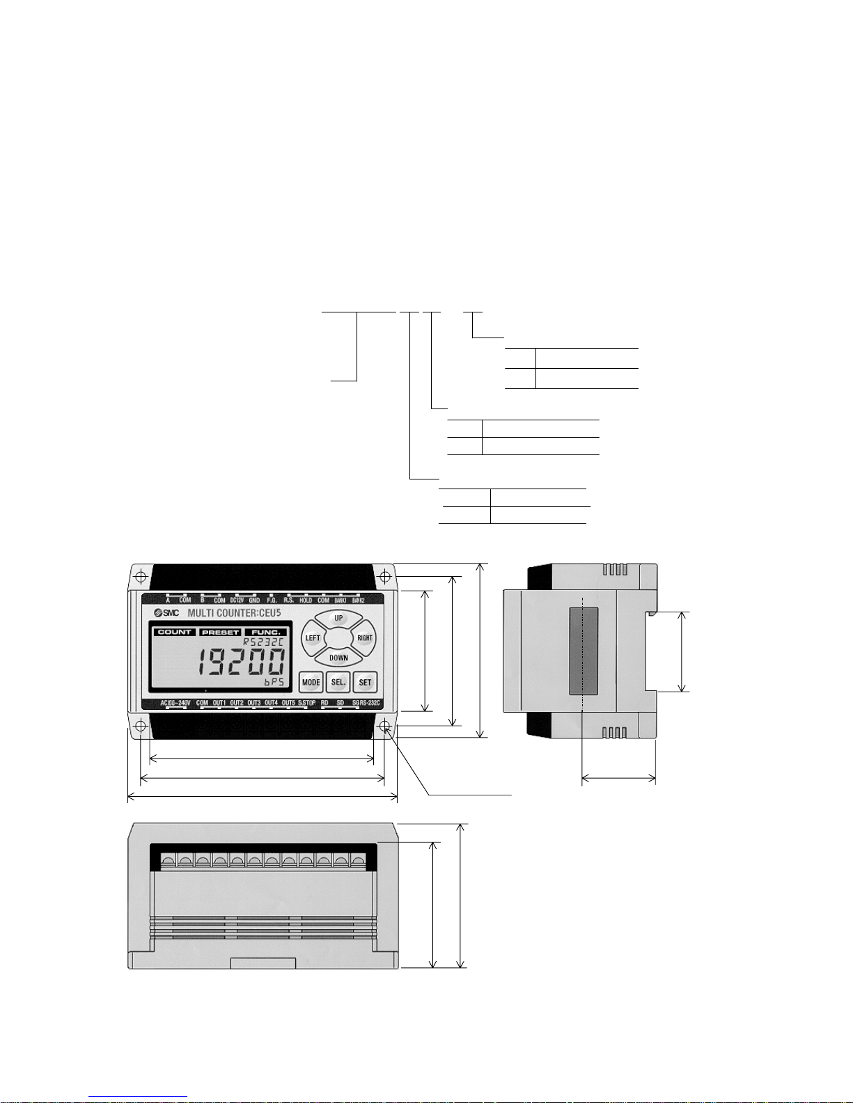
2-2. Outside Dimensions
4-φ4.5
64
59
80
125
104
56
68
±0.2
113
±0.2
33.5
35.5
DIN rail groove
- 4 -
Chapter 3: Functions and Terminology
Terms on output are defined as follows in this operation manual.
Output signals
Output signals are signals from CEU5 to PLC/ PC: preset output, Cylinder stop output and BCD
output.
Preset output
This is the output signal sent to PLC/ PC when counts are matched with the
set values. Upper and lower limits can be set in preset output. Output form
can be selected from three types.
Cylinder stop
output
This is the output signal sent to PLC/ PC when pulses coming from encoder
do not change for a certain time. This output signal provides better timing
for reading preset output and outputs sent to PLC/ PC.
BCD output This is the output signal of a value indicated on CEU 5 sent to PLC/ PC for
64ms.
Preset output forms
Preset output forms are three types of output in preset output: compare, 1-shot and hold. Refer to
“Preset output forms list” in a following page for details.
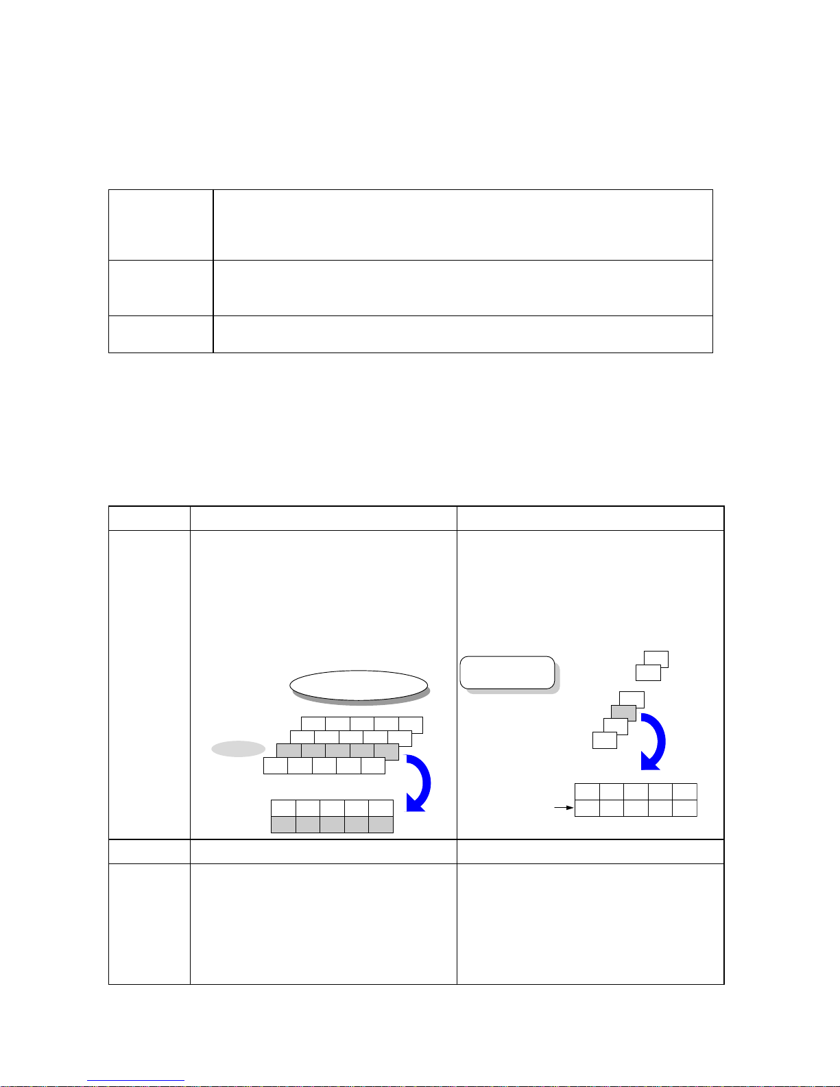
Output method
Preset output can be selected from two methods: normal output and binary output. No. 1 through
No. 31 can be stored in preset setting. However, No. 21 through No. 31 can be used only for
binary output.
Normal output Binary output
Features
・Allocate one output terminal to one preset
number.
・Divide preset numbers of 1 through 20 into four
blocks, which are called bank 1 through 4
respectively.
・Preset output is active for a preset number of a
bank selected.
・Bank can be switched by external signals.
16 17 18 19 20
11 12 13 14 15
6 7 8 9 10
① ② ③ ④ ⑤
Preset No.
Bank 4
Bank 3
Bank 2
Bank 1
If bank 2 is selected
Preset No.
Output terminal
6 7 8 9 10
6 7 8 9 10
1 2 3 4 5
・Send signals to PLC/ PC to indicate preset
numbers matched with counts by using all the
five output terminals.
・To obtain information on preset output, output
terminals 1 through 5 need to be checked.
・This output is active only when cylinder stopped.
Passed points are not outputted.
4
① ② ③ ④ ⑤
Output terminal
Preset No.
If a count matches with
preset No. 3
3
2
1
31
30
・
・
On On Off Off Off
Pattern showing No. 3
Memory 20 presets(with bank function used) 31 presets
Application
・20 types of work can be sorted to Good or No
Good when the types of work are known in
advance.
・Another equipment can be operated in the timing
of preset output in CEU5.
・This output can be used for switching preset
output for work group or process.
・31 types of work can be classified without
external switching.
・Unknown work types transferred can be classified
into a maximum of 31 types.
- 5 -
CEU5 has the following features.
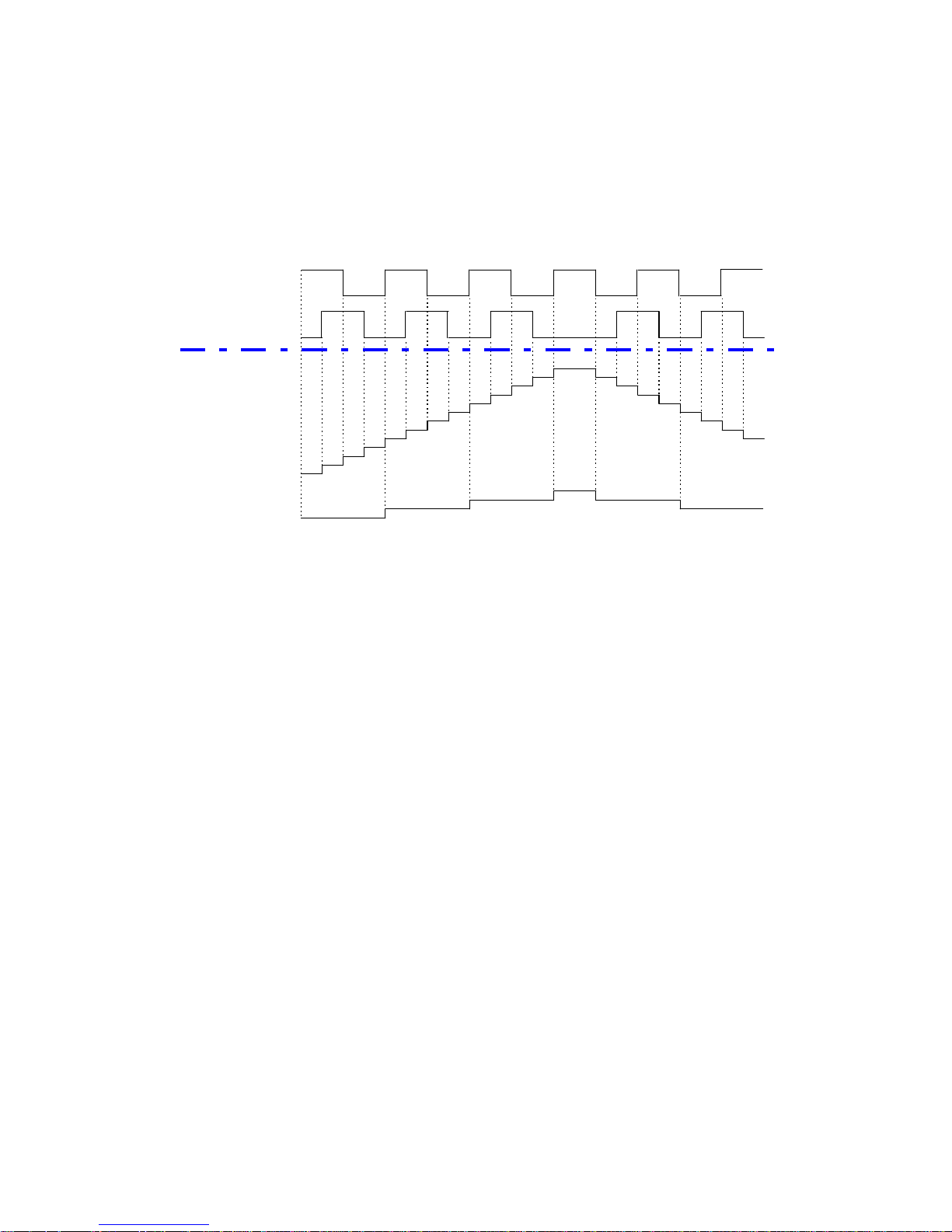
(1) Multiplication function
All the pulses are multiplied by four times multiplier in hardware at input of A/B quadrature while it
is multiplied by two times multiplier or no multiplier in software. This will provide higher
resolution of measurement and improve the accuracy of the origin. The following figure
shows the relation between count by four times multiplier and no multiplier.
A
-phase pulse
B-phase pulse
Count
11
12
M u ltip lie r
×4
0
1
2
3
2
1
5
9
10
8
0
1
2
3
4
6
7
5
11
10
9
8
7
6
4
M u ltip lie r
×1
* Multiplier
×1 : Use quadrature input signals for a bi-directional count.
* Multiplier
×4 : Use quadrature input signals to count on leading and trailing edges of "A"
and "B" for a bi-directional count.
(2) Switching of A/B quadrature input and UP/ DOWN individual pulse input
Accommodate to encoders with A/B quadrature output and UP/ DOWN individual pulse output.
(3) Pre-scale function
Function for the user to optionally set the number indicated for one count.
(4) Setting of tolerances for preset values
Upper and lower limits can individually set to preset values. Each set value can be either positive
or negative. For example, tolerances of + 0.04 and + 0.01 can be inputted as in the tolerance
indications in drawings.
(5) Bank functions (4 channels)
Preset output can be sent from 5 points simultaneously. Preset values of 5 points are
grouped into one frame (bank) and there are four banks from 1 to 4. A maximum of 20 types
of work can be classified by switching these banks. Refer to “Correspondence of bank and
bank terminals at switching” in a following page.
(6) Binary output (31 points)
Preset output can be sent from 31 points without bank switching by sending signals from five
output terminals in binary output method (If output signals are overlapped, a signal of smaller
preset No. is sent. Output form is compare output only).
- 6 -

(7) Cylinder stop output
Cylinder stop output is a signal sent out from S. STOP terminal when
pulse signals from encoder do not change for a certain period of time. This output signal
provides better timing for reading preset output and outputs sent to PLC/ PC.
(8) Hold function (for RS-232C communication or BCD output)
The display on the counter is held during a hold signal is coming in. With RS-232C
communication or BCD output, the data indicated is sent out. Even if reading process of the
PLC is delayed, the count when the hold signal is inputted can be taken in (The display is
held, however, counting is continued inside. At this time, preset output is sent out according
to the count inside with or without hold signal).
(9) Backing up of counts (changeable between hold and non-hold)
Back up counts after power interruptions. This function can be selected either ON or OFF.
(10) RS-232C communication function
Count output and setting of each function can be done by PLC (with RS-232C functions) or PC in
serial transmission of the RS-232C specifications.
(11) BCD output function (equipped only with CEU5*B-* type)
Send out counts by BCD coding. This function also allows taking in counts by PLC or PC and
connecting to external large indicator.
- 7 -

Chapter 4: Specifications
Product Multi-counter
Mounting Surface mount (with DIN rail or set screws)
Operation Addition and subtraction
Mode Operation mode, Preset data setting mode, Function setting mode
Reset External reset terminal
Indication LCD (with back-light)
Digits 6 digits
Memory Backup
{medium}
Set values (Constantly hold), counts (hold/ non-hold switching)
{E2 ROM (alarm indication at approx. 800,000 data writings)}
Input signal Count input, control signal input (reset, hold, bank selection)
Count Input No-voltage input
Pulse signal input A/B quadrature input, UP/ DOWN individual pulse input (Note 1)
Counting speed 100 kHz (Note 2)
Control signal input "For connecting COM terminal to 12VDC or 24VDC"
Conduction between each input terminal and GND terminal.
"For connecting COM terminal to GND terminal"
Conduction between each input terminal and 12VDC or 24VDC terminal.
power supply for sensor
12VDC ±10%, 60 mA
Preset output form Compare, hold, one-shot (fixed at 100 ms)
Output method Individual 5 points output, binary code output
Output time lag 5 ms or less (in normal output)/ 60ms or less (in binary output)
Communication RS-232C
Proof voltage Between case and AC line: 1500 VAC, 1 minute
Between case and signal earth: 500 VAC, 1 minute
Insulation resistance
Between case and AC line: 500 VDC, 50MΩor more
Ambient temperature
0℃ to + 50℃ (No freezing)
Ambient humidity 35% to 85%RH (no dew condensation)
Noise resistance
Square wave noise by noise simulator (pulse width: 1μs)
Between power terminals: ±2000V, input line: ±600V
Vibration proof Durable to 10 Hz to 55 Hz and amplitude of 0.75 mm in X, Y and Z directions
for 2 hours each.
Impact resistance Durable to 10 G in X, Y and Z directions for three times each.
Weight Approx. 350 g
CEU5*-* (Without "B") CEU5*B-*
Output signal Preset output , cylinder stop output Preset output , cylinder stop output ,
BCD output
CEU5*-* (Without "P") CEU5P*-*
Output transistor type
NPN open collector (Max.30VDC,50mA) PNP open collector (Max.30VDC,50mA)
CEU5** CEU5**-D
Power voltage
100VAC to 240VAC (±10%)
24VDC (±10%)
Power consumption 20VA or less 10W or less
Note 1: Pulse signals can be counted by CEU5 should meet “Input waveform requirements” in the next
page.
Note 2: Counting speed of 100 kHz is provided when “Input waveform requirements” are met. When
signals are
damped due to long wires, taking countermeasures such as reducing the speed
is required.
- 8 -
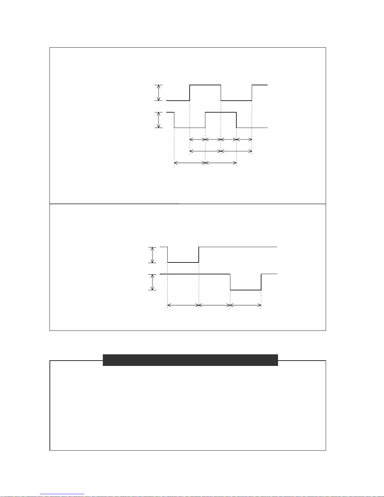
Input waveform requirements
[A/B quadrature input]
Two count channel input (A and B) in quadrature (90°nominal phase relationship).
A maximum of input waveform shall be 100 kHz, and the waveforms of A and B phases at this
time are as below.
BCDA
EF
GH
+12V
±10%
+12V
±10%
Channel A
"A-phase pulse"
Channel B
"B-phase pulse"
A : requires 2.5μsec or more E : requires 5μsec or more
B : requires 2.5μsec or more F : requires 5μsec or more
C : requires 2.5μsec or more G : requires 5μsec or more
D : requires 2.5μsec or more H : requires 5μsec or more
[UP/ DOWN individual pulse input]
"UP pulse" is a input to add the count, and "DOWN pulse" is a input to subtract the count.
A maximum of input waveform shall be 100 kHz, and the waveforms of UP and DOWN pulses
are as below.
CBA
+12V
±10%
+12V
±10%
Channel A
"UP pulse"
Channel B
"DOWN pulse"
A : requires 5μsec or more C : requires 5μsec or more
B : requires 5μsec or more
Not applicable to absolute type encoders.
When using encoders from other manufacturers, check if the encoders are within the
specification range of CEU5 before use (Refer to the previous page and this page).
Performance test is given to SMC Monosashi-kun (Scale reading cylinders) and CEU5
using a 23 meter long exclusive extension cable. Wiring length depends on the specifications
of the encoder and cable given by each manufacturer and it should be checked before use.
CEU5 has a power supply for encoder (12VDC, 60 mA). If an encoder requires a power
other than 12VDC or large current consumption, use a separate power supply.
“When using encoders from other manufacturers”
- 9 -
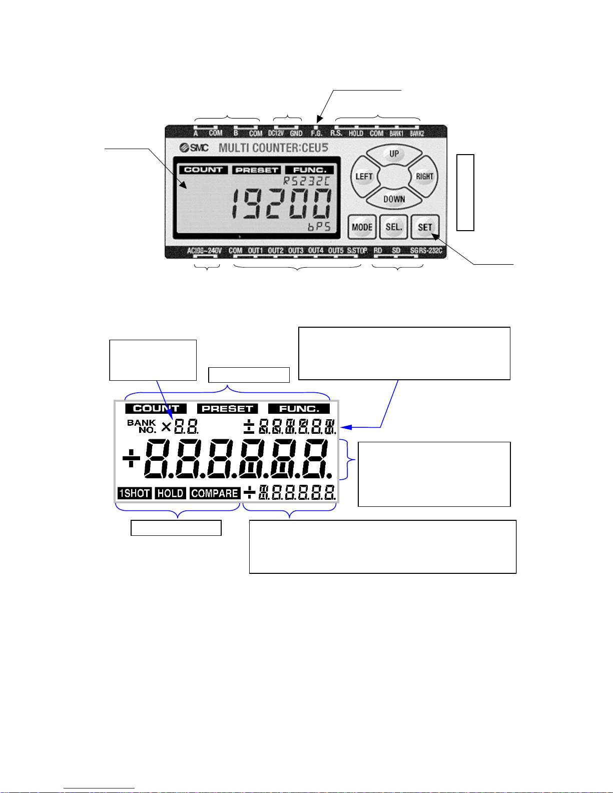
Chapter 5: Description of Each Part
Indication
Pulse input terminal
External
power
supply
Control signal input
Output terminal Communication terminal
Power
BCD
output
connector
(side)
Operation
key
Frame ground
[Indication part details]
Bank No.
Preset No.
Multiplication
Upper limit
Function items
"PRESCL", "OFFSET", "STOP", "OUTPUT",
"INPUT", "BACKUP", "RS232C", "UNIT"
Mode indication
Counts, Preset values, Count
value per pulse, Offset setting,
Cylinder stop output, Output
type, Input type, Backup,
RS-232C, Unit No.
Output type (bin)/ output state indication
(□_□_□)
Cylinder stop output indication
( _ _ _ _ _ S)
Lower limit
Connected model (CEP1, CE1, MANUAL)
RS-232C communication speed unit (bps)
Preset output form
- 10 -
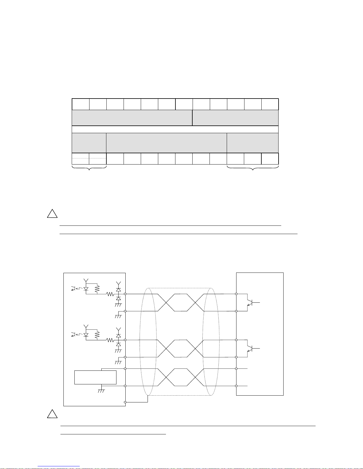
Chapter 6: Wiring
6-1. Terminal block arrangement
A B COM DC12V
240VAC
VDC (-)
COM
100 -
(+) 24
GND F.G. RESET HOLD BANK1 COM BANK2
COM OUT1 OUT5OUT4OUT3OUT2 S.STOP RD SG SD
(UP pulse)
B-phase pulse input
Sensor input
common
Sensor power
output
Sensor input
common
Sensor power
GND
FG terminal
Reset input
Hold input
Control input
common
Bank 1 selection
Bank 2 selection
Power input
terminals
Output signal
common
Output terminal 1
Output terminal 2
Output terminal 3
Output terminal 4
Output terminal 5
Cylinder stop
output
Serial
transmission
Sensor input block
(connect to Monosashi-kun or encoder)
Control input block
(input control signals)
Counter
power
suppl
y
Output block (terminals for preset output and
cylinder stop output)
Serial transmission block
(
terminals for RS-232C
communication)
A-phase pulse input
(DOWN pulse)
!
Caution
The COM terminal of each block is insulated from COM terminals of other blocks
(However, COM terminal and GND terminal in sensor input block are connected inside).
6-2. Wiring of sensor input part
Change the wiring combination of white-A/blue-COM and yellow-B/brown-COM like white-B/blue-COM
and yellow-A/brown-COM in pair to reverse the count direction.
(
)
1kΩ
(
)
+12V
+12V
680Ω
Built-in sensor power
supply
12VDC, 60 mA
A
B
COM
COM
+12V
GND
F.G.
CEU5 sensor input part SMC M onosashi-kun series
White
Blue
Yellow
Brown
Red
Black
1kΩ
+12V
+12V
680Ω
!
Caution
Wire colors are for SMC Monosashi-kun series. For other encoders, check the wiring
specified in encoder operation manual.
- 11 -
6-3. Wiring of control signal input part (reset, hold and bank selection)
Each control signal shall be inputted in a circuit using a transistor that allows current flow
of 15 mA or more, or a circuit of contact output. Input time for reset signal shall be 10 ms
or longer. Bank selection and hold are active only in signal inputting.
COM is common for each signal input as well as for NPN and PNP input types. Use a
power of 24VDC or 12VDC and connect to DC- for PNP input and to DC+ for NPN input.
CEU5 control signal input part
(
)
Control signal input
COM
1kΩ
2.2kΩ
(reset, hold and bank
selection)
Or
Power (24VDC or 12VDC)
6-4. Wiring of output part (preset output and cylinder stop output)
The following shows the wiring for preset output (OUT 1 through 5) and cylinder stop
output (S. STOP) with two output types: NPN and PNP.
Model Wiring
CEU5
CEU5B
CEU5-D
CEU5B-D
NPN transistor (open collector output)
Load
COM
OUT
Power
(30VDC or less)
50 mA or
CEU5P
CEU5PB
CEU5P-D
CEU5PB-D
PNP transistor (open collector output)
Load
COM
OUT
Power
(30VD C o r less )
(50 m A or le ss)
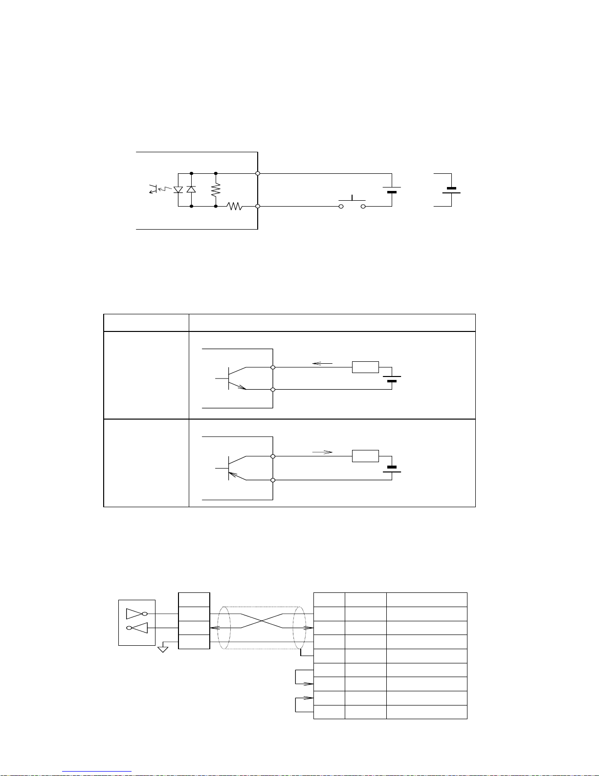
6-5. Wiring of RS-232C
Electric feature: complying with EIA RS-232C
Terminal block signal name
SD
RD
SG
SD
RD
SG
Equivalent to
LT1181
FG
Symbol Symbol
Counter side Host computer side
RS- 232C RS- 232C
Input
Output T ransm itted data
Received data
Signal ground
Signal
direction
Signal
-
Frame ground
-
RS
Request to sendOutput
CS
C le a r to s e n dInput
DR
D a ta s e t re a d yInput
ER
D a ta te rm ina l re a d yOutput
- 12 -
 Loading...