

Page 1

DOCUMENT No.: CE*-OMG0104-F
Brake Position Determination System’s
User Guide
PRODUCT NAME :
MONOSASHI-KUN WITH BRAKE
MODEL :
CE2:MONOSASHI-KUN WITH BRAKE
CEU2:CONTROLLER
○ Read this operation manual carefully to
understand before installation and operation.
○ Pay extra attention on the clause concerning the
safety.
○ Keep this operation manual available whenever
necessary.
SMC CORPORATION
Page 2

Contents
Read Before Use ··············································································· 1
1. General ························································································ 7
1-1. Features
1-2. Position Control
1-3. Positioning at Stroke End
2. System Configuration ······································································ 8
2-1. System Checking Flow Chart
2-2. System Configuration
2-3. Recommended Circuit Design
3. Specifications ··············································································· 13
3-1. Cylinder Specifications
3-2. Controller Specifications
3-3. Sensor Specifications
4. Model ·························································································· 15
4-1. Cylinder
4-2. Controller
4-3. Extension Cable
5. External Dimension Drawing ···························································· 17
5-1. Monosashi-kun with Brake
5-2. Controller
5-3. Extension Cable
6. Part Identification ·········································································· 21
6-1. Monosashi-kun with brake
6-2. Controller
7. Installation & Wiring ······································································· 22
7-1. Installation
7-1-1 Installation of Cylinder
7-1-2 Installation of Controller
7-2. Wiring
7-2-1 The connection of Power Supply
7-2-2 The connection of Extension Cable
7-3. Input Signal’s Wiring
7-3-1 Input Signal Wiring Diagram
7-3-2 Input Signal Content
7-3-3 Input Signal Wiring
7-3-4 OUTPUT Signal Wiring
7-3-5 Solenoid Valve Wiring
7-3-6 Sequencer
8. Timing Chart ················································································· 28
9. Data Setting ················································································· 36
9-1. Preset Data Setting
9-1-1 Data Classification & Content
9-1-2 Input Method
9-1-3 Confirmation of Set Data
Page 3

9-2. Program Setting
9-2-1 Input Method
9-2-2 Confirmation of Input Data
9-3. Selection of Dip Switch
10. Driving ······················································································· 44
10-1. Setting of Origin Direction
10-2. Adjustment of Air Balance
11. Error Messages & Countermeasures ··············································· 45
11-1. Controller
11-2. Brake Unit’s Life Span
12. Appendix ···················································································· 49
12-1. Data Sheet
Specifications are subject to change without prior notice
Page 4

Read before Use
These safety instructions are intended to prevent a hazardous situation and/or equipment damage.
These instructions indicate the level of potential hazard by label of “Caution”, ”Warning”, or ”Danger”.
To ensure safety, follow the instructions below as well as ISO/IEC, JIS
*1)
and other safety laws
*2)
.
Caution
Operator error could result in injury or equipment damage.
Warning
Operator error could result in serious injury or loss of life.
Danger
In extreme conditions, there is a possible result of serious injury or
loss of life.
*1) ISO 4414: Pneumatic fluid power - General rules relating to systems
ISO 10218-1: 2006: Robots for industrial environments - Safety requirements - Part 1: Robot
IEC 60204-1: Safety of machinery - Electrical equipment of machines - Part 1:General
requirements
JIS B 8370: General Rules for Pneumatic systems
JIS B 9960-1: Safety of machinery - Electrical equipment of machines - Part 1: General
requirements
JIS B 8433-1:2007: Robots for industrial environments - Safety requirements - Part 1: Robot
*2) Labor Safety and Sanitation Law etc.
Warning
1. The compatibility of pneumatic equipment is the responsibility of the person who designs the
pneumatic system or decides its specifications.
Since the products specified here are used in various operating conditions, their compatibility for
the specific pneumatic system must be based on specifications or after analysis and/or tests to
meet your specific requirements. Ensuring the initial performance and safety are the responsibility
of the person who decides the compatibility of the pneumatic system. Pneumatic systems should
be constructed after full review of the details of the products other than specifications and
possibilities of failures by checking the latest product information.
2. Only trained personnel should operate poneumaticallly operated machinery and equipment.
Assembly, handling, or repair of pneumatic systems should be performed by trained and
experienced operators.
3. Do not service machinery/equipment or attempt to remove component until safety is confirmed.
a. Inspection and maintenance of machinery/equipment should only be performed after
confirmation of safe locked-out control positions.
b. When equipment is to be removed, confirm the safety process as mentioned above. Cut the
supply pressure for this equipment and exhaust all residual compressed air in the system.
c. Before machinery/equipment is re-started, take measure to prevent shooting-out of cylinder
piston rod etc.
4. Contact SMC and take necessary safety measures if the products are to be used in any of the
following conditions:
a. Conditions and environments beyond the given specifications, or if products are used outdoors.
b. Installation on equipment in conjunction with atomic energy, railway, air navigation, vehicles,
medical equipment, food and beverages, recreation equipment, emergency stop circuits, press
applications, or safety equipment.
c. An application which has the possibility of having negative effects on people, property, or animals,
requiring special safety analysis.
d. When used in an interlock circuit, dual interlock such as mechanical protection is necessary in
case of accident. Periodical inspection is also necessary to confirm proper operation.
!
!
!
!
Page 5

Operating and Storage Environments
Warning
1. Envionments to avoid
Avoid using or storing the products in the
following environments which may cause
failures.
If the products need to be used or stored in
those environments, take necessary measures.
a. Place where ambient temperature exceeds
the range of 0℃ to 60℃.
b. Place where ambient humidity exceeds the
range of 25% to 85% RH.
c. Place where condensation occurs due to
sudden temperature change.
d. Place where atmosphere containing corrosive
gas, flammable gas or organic solvent.
e. Place where atmosphere containing
con-ductive powder such as dust and iron
chips, oil mist, salt, or organic solvent, or
splashing cutting chips, dust and cutting oil
(water , liquid) over the products.
f. Place where the products are exposed to
direct sunlight or radiated heat.
g. Place where strong electromagnetic noise is
generated (place where strong electric field,
strong magnetic field or surge is generated).
h. Place where static electricity is discharged or
condition that the products have electrostatic
discharge.
i. Place where strong high frequency is
gene-rated.
j. Place where damages of thunder are
expected.
k. Place where vibration or impact is directly
given to the products.
l. Condition that the products are deformed by
force or weight applied.
2. Do not close any objects which are affected
by magnets.
Since magnets are built in cylinders, do not close
magnetic disks, magnetic cards or magnetic
tapes. The data may be destroyed.
Precaution on Design
Warning
1. There is a possibility of dangerous sudden
action by cylinders if sliding parts of
machi-nery are twisted due to external forces,
etc.
In such cases, human injury may occur; e. g., by
catching hands or feet in the machinery, or
damage to the machinery itself may occur.
2. Provide a cover to minimize the risk of
human injury.
When a driven object or moving parts of a
cylinder may cause the risk of human injury,
design a structure to avoid contact with human
body.
3. Securely tighten all stationary parts and
connected parts of cylinders so that they will
not become loose.
Tighten cylinders securely especially when they
are used in high frequency or in locations where
direct vibration or impact shock, etc. will be
applied to the body of the cylinder.
4. Deceleration circuits or shock absorbers are
needed in some cases.
If a driven object travels at a high speed or is
heavy, impact will not be sufficiently absorbed
only with the cylinder cushion. In such cases,
use a circuit to decelerate the cylinder speed
before the cushion becomes effective or use
external shock absorbers to reduce impact. At
this time, take the rigidity of machinery into
account.
5. Consider possible drop of pressure in circuit
due to power outage.
For cylinders used in clamping mechanism, a
work may become loose due to less clamping
force by pressure drop in circuit at the time of
power outage. Install safety devices to prevent
human injury and machinery damage. Measures
should be taken to prevent drop of hanging or
lifing equipment.
6. Consider possible loss of power sources.
Measures should be taken to protect against
human injury and machinery damage in the
event that there is a loss of air pressure,
electricity or hydraulic power.
7. Design circuit to prevent shooting out of a
driven object.
A driven object is quickly shot out when pressure
is supplied from one side of the piston after air in
the cylinder is exhausted in such cases that
cylinder is actuated by exhaust center type of
directional control valve or started after residual
air is exhausted from the circuit. At this time,
human injury may occur; e.g., by catching hands
or feet in the machinery, or damage to the
machinery itself may occur. Therefore, the
machine should be designed and constructed to
prevent shooting out.
!
!
Page 6

3
8. Consider emergency stops.
Design the machinery so that human injury
and/or damage to machinery and equipment will
not be caused when machinery is stopped by a
safety device under abnormal conditions, a
power outage or a manual emergency stop.
9. Consider actions when operation is restarted
after an emergency stop or abnormal stop.
Design the machinery so that human injury or
equipment damage will not occur upon restart of
operation. When the cylinder is required to return
to the initial position, provide the equipment with
a safe override.
10.Construct the machinery so that moving
objects and the moving parts of the cylinder
with brake do not come into direct contact with
the human body.
11.Use a balanced circuit in which lurching of the
cylinder is prevented. When operation is locked
in specified intermediate positions of the stroke,
and air pressure is applied to only one side of
the cylinder, the piston will lurch when the lock
is released. This might cause injury or damage
to machinery.
Selection
Warning
1. Confirm the specifications.
The product in this manual is designed to be
used only in industrial compressed air system.
The product should not be used with pressures
or temperatures outside the range of the
specifications, as this may cause damage or
malfunction, etc.
2. Intermediate stop
When cylinder piston is stopped intermediately
by 3-position closed center type of directional
control valve, intermediate stop positions may
not be as precise and exact as hydraulic
operation due to compressibility of air. Valves
and cylinders are not guaranteed for zero air
leakage, and stop position may not be held in a
long period of time. Consult SMC for long term
holding of stop positions.
3. When a cylinder is in a no-load and locked state,
the holding force (maximum static load) is the
lock’s ability to hold a static load that does not
involve vibrations or shocks. To ensure braking
force, the maximum load must be set as described
below.
①For constant static loads, such as for drop
prevention:
35% or less of holding force (Maximum static
load)
Note) For applications such as drop prevention,
consider situations in which the air source
is shut off, and make selections based on
the holding force of the spring locked
state. Do not use the pneumatic lock for
drop prevention purposes.
②When kinetic energy acts upon the cylinder,
such as when effecting an intermediate stop,
there are constraints in terms of the allowable
kinetic energy that can be applied to the
cylinder in a locked state. Refer to the
allowable kinetic energy of the respective
series. Furthermore, during locking, the
mechanism must sustain the thrust of the
cylinder itself, in addition to absorbing the
kinetic energy. Therefore, even within a given
allowable kinetic energy level, there is an
upper limit to the amount of the load that can
be sustained.
- Maximum load for horizontal mounting: 70%
or less of the holding force (Maximum static
load) for spring lock
- Maximum load for vertical mounting: 35% or
less of the holding force (Maximum static
load) for spring lock
③In a locked state, do not apply impact, strong
vibrations or rotational forces. Any impact,
strong vibrations or rotational forces from
external sources could damage or shorten
the life of the lock unit.
④Although the cylinder can be locked in both
directions, be aware that its holding force is
smaller in one of the directions. Holding
force at piston rod extended side is approx.
15% less.
Caution
1. Mount speed controller and adjust cylinder
operation speed gradually from low speed to
a desired speed.
Air Supply
Warning
1. Do not use the product out of the specified
ranges for pressure and temperature to
pre-vent equipment damage and
mal-function.
!
!
!
Page 7
4
①Operating pressure:
Actuating part: 0.1 – 1.0MPa
Braking part
: 0.3 – 0.5MPa
②Fluid & ambient temperature: 0 to 60C
2. Use clean air.
Do not use the product with compressed air
includes chemicals, synthetic materials
(including organic solvents), salinity, corrosive
gases, etc., as this may cause damage or
malfunction.
Caution
1. Install air filter.
Install air filter before and in vicinity of valve. The
filter should be able to collect particles of 5
microns or smaller. A large quantity of drain may
cause malfunction of pneumatic components.
2. Install after cooler, air dryer, auto drain, etc.
Compressed air that includes excessive
condensate may cause malfunction of valve and
other pneumatic equipment. To prevent this,
install after cooler, air dryer, auto drain, etc.
Pneumatic circuit
Warning
1. Be certain to use a pneumatic circuit which will
apply balanced pressure to both sides of the
piston when in a locked stop. (Refer to Chapter 6
for recommended pneumatic circuit.)
In order to prevent the cylinder lurching after a
locked stop, use a circuit which applies balanced
pressure to both sides of the piston when restarting
or when manually releasing the lock, thereby
canceling the force generated by the load in the
direction of piston movement.
2. Use a solenoid valve for unlocking which has a
larger effective area, as a rule 50% or more of
the effective area of the cylinder drive solenoid
valve. (Refer to Chapter 6 for recommended
pneumatic components.)
The larger the effective area is, the shorter the
locking time will be, and stopping accuracy will
be improved.
3. Place the solenoid for unlocking close to the
cylinder, and no farther than the cylinder drive
solenoid valve.
The shorter the distance from the cylinder, the
shorter the overrun amount will be, and stopping
accuracy will be improved.
4. Allow at least 0.5 seconds from a locked stop
(intermediate stop of the cylinder) until release of
the lock.
When the locked stop time is too short, the
piston rod may lurch at a speed greater than the
control speed of the speed controller.
5. When restarting, control the switching signal for
the unlocking solenoid valve so that it acts before
or at the same time as the cylinder drive solenoid
valve.
If the signal is delayed, the piston rod may lurch at
a speed greater than the control speed of the
speed controller.
Installation
Warning
1. Connect the rod end and the load with the lock
released.
2. Ensure that the equipment operates properly
before the use.
3. Operation manual
Do not install the products unless the safety
instruction have been read and understood.
Keep this operation manual on file for future
reference.
Caution
1. Maintenance space
When installing the products, allow space for
maintenance.
2. Installation of jigs
When hardware and nuts are screwed into the
piston rod end, the piston rod should be fully
retracted.
Use double nuts to fix a work since Precision
MONOSASHI-KUN (Scale Reading Cylinder)
does not have any parallel parts at the rod.
3. Do not give strong impact and/or excessive
moment when work is mounted.
External force other than allowable moment may
cause rattle at guide part and/or increase in
sliding resistance.
4. Use the product in such a condition that load
is always applied in the axial direction of the
piston rod.
When load is applied in other directions than
cylinder axial direction, regulate the load itself
by the guide.
Perform a complete centering when cylinder is
mounted.
5. Be careful to avoid scratches or dents, etc. on
the sliding sections of the piston rod.
! ! !
!
Page 8
5
Wiring
Warning
1. Preparation for wiring
Shut off the power before wiring (including
insertion and removal of connectors). Mount a
protective cover on the terminal block after
wiring.
2. Check the power
Make sure the power has sufficient capacity and
voltages are within the specified range before
wiring.
3. Grounding
Ground terminal block F.G. (Frame Ground).
Do not ground it with devices generating strong
electromagnetic noise.
4. Check wiring
Incorrect wiring may cause damage or
malfunction of the products. Make sure the
wiring is correct before operation.
Caution
1. Separation of signal wires from power wire
Avoid common or parallel wiring of signal and
power wires to prevent malfunction due to noise.
2. Wiring arrangement and fixation
Avoid bending cables sharply at connector part
or electrical entry in wiring arrangement.
Inproper arrangement may cause disconnection
which in turn causes malfunction. Fix cables
close enough not to give excessive force to the
connector.
Piping
Caution
1. Before piping
Remove cutting chips, cutting oil, dust, etc. in
piping by flushing or cleaning before piping.
Care should be taken especially that any cutting
chips, cutting oil, dust, etc. do not exist after a
filter.
2. At piping
①Foreign matter should not enter. Entering of
foreign matter will cause malfunction.
②Cutting chips and sealing materials at piping
threads should not enter valves when piping
and fittings are screwed in. Leave 1.5 to 2
threads when seal tape is used.
Lubrication
Caution
1. Lubrication of cylinder
①This cylinder is pre-lubricated and can be used
without lubrication.
②In case of lubrication, use a equivalent of the
turbine oil type 1 ISO VG32. Once lubrication
is performed, it should be continued since the
initial lubricant flows out causing malfunction.
Adjustment
Caution
1. The locks are manually disengaged when the
cylinder is shipped from the factory. Be sure to
change them to the locked state before using
the cylinder.
2. Adjust the cylinder’s air balance. In the state in
which a load is attached to the cylinder,
disengage the lock and adjust the air pressure
on the rod side and the head side of the cylinder
to obtain a load balance. By maintaining a
proper air balance, the piston rod can be
prevented from lurching when the lock is
disengaged.
3. Adjust the mounting position of detection
devices such as autoswitches.
Sensor unit
Caution
1. Do not remove the sensor unit.
The position and sensitivity of the sensor is
adjusted properly before shipment.
Removing or replacing the sensor may cause
malfunction.
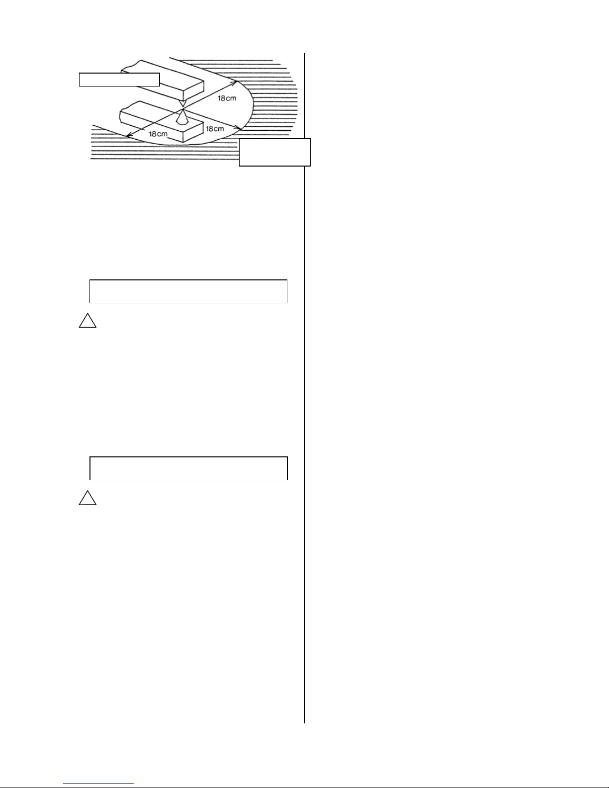
2. Operate the system with an external magnetic
field of 14.5mT or less.
Strong magnetic field in the vicinity may cause
malfunction, since CE2 sensor is magnetic type.
This is equivalent to a magnetic field of
approximately 18cm in radius from a welding area
using a welding current of almost 15,000 amperes.
To use the system in a magnetic field that exceeds
this value, use a magnetic material to shield the
sensor unit
!
! ! ! ! !
Page 9
6
3. Do not pull sensor cable strongly.
Such action may cause failure.
4. Water shall be kept away from the sensor unit to
avoid failure. (IP65 Protection)
5. Power supply line
Do not mount any switch or relay to power
supply line (12 VDC to 24 VDC).
Measurement
Caution
SMC products are not intended for use as
instruments for legal metrology.
Measurement instruments that SMC manufactures
or sells have not been qualified by type approval
tests relevant to the metrology (measurement) laws
of each country. Therefore, SMC products cannot
be used for business or certification ordained by the
metrology (measurement) laws of each country.
Maintenance and Check
Warning
1. Performing regular check
Check regularly that the products do not operate
with failures unsolved. Check should be done
by trained and experienced operators.
2. Dismantling of product and supply/exhaust
of compressed air.
Before dismantling, ensure that drop preventing
and runaway preventing treatments are properly
provided, shut the power source of air supplied,
and exhausts compressed air in the system.
When starting operation again, operate the
product with care after ensuring that a treatment
for preventing extrusion is properly provided.
3. Prohibition of disassembly and modification
To prevent accidents such as failures and
electric shocks, do not remove the cover to
perform disassembly or modification. If the
cover has to be removed, shut off the power
before removal.
4. Disposal
Request a special agent for handling industrial
waste to dispose the products.
!
Operating
range
Welding machine
!
Page 10
7
1.General
1-1 Features
Controller (CEU2) is a special controller designed for Monosashi-kun with Brake. Upon the input, controller
will stop the cylinder, smoothly and precisely at position as inputted.
Stopping positions of Monosashi-kun with Brake are stored into “Step”, ranging from step 1 to 32. Steps will
be grouped together and form as “Program”. CEU2 allows maximum storage of 16 programs.
Following are CEU2’s special feature: -
1. Predictive Control & Learning Function
(Allow High Repeatability and Precision, ±0.5mm)
With learning function, after every execution, brake point will be amended, according to the deviation of
stopping position from setting position.
2.Equipped Function with Retries→If stopping position deviates from setting position’s tolerance, retries
function will execute to revise the brake point.
Program
P1
P2
P3
・・・・・
P16
Step
S1
S1
S1 S1 S2
S2
S2 S2
・
・
・
・
・
・
・
・
・
・
・
・
S32
S32
S32
S32
Brake Point Setting Point Stopping Position
First Move
Deviation
Predictive of OverRun with taking into the consideration of bore size, cylinder speed and load rate.
Brake Point
Stopping Position
Second Move or above
With reference to previous deviation, brake point was shifted.
Brake point Setting point
停止位置
Stopping Position
Tolerance
Deviation
Retract position
of cylinder
about 30mm Cylinder will retract 30mm
and re-determine position.
Brake point
Stopping Position
Position , falling within the tolerance range, is determined.
Page 11

8
3. Error Detector
When System is found faulty, error detector will take action, detect and analyze error. Finally, error
messages will be displayed. Thus, ease of debugging time.
4. DIN Rail installation is possible.
1-2 Position Control
1. With controller, valve outputs to achieve precise positioning.
2. For the situation whereby cylinder stopping position does not fall into the tolerance range, retries will
be performed. First, it will retract (30mm), and then extend to achieve setting position.
3. With learning ability, brake point will be recognized and thus lead to precise positioning with taking
into the consideration of factors like loading & pressure condition, momentum & impact when
stopping.
4. Stopping method applied is through air balance and brake to lock the movement. While brake applies
the combination of spring and pneumatic locking method.
5. Position is determined when positioning falls on the setting tolerance range.
6. Position determination will follow the sequence of selected program’s steps.
7. Only programs are available for selection. Program steps are not selectable.
1-3 Positioning at Cylinder Rod End
Do not use cylinder with cushion, if determined position falls at cylinder rod’s end (front or back). This is
due to drastical change of speed occurring at the stroke end will lead to imprecision and easy occuring
of learning error (Err 6).
2. System Configuration
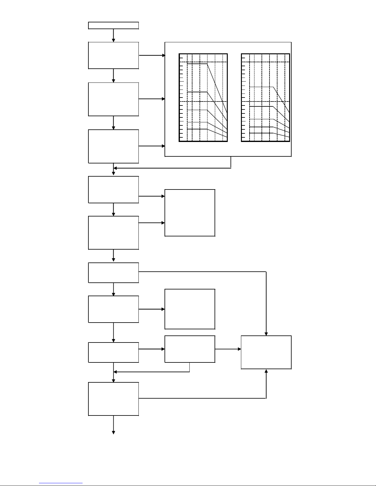
2-1 System Checking Flow Chart
《CE2 (Monosashi - kun with brake) + CEU2 (Controller)》
Refer to check Flow, showing at next page, to determine brake position, so as to reduce the
possibility of occurring errors, which are mostly due to the stopping precision, caused by brake
position.
Page 12
9
NO
NO
OK
YES
NO
NO
NO
YES
Install driving and
brake valve
seperately.
NO
Continue on page 4
YES
Where there is
pressure & speed
changes during
simultaneous action.
YES
Due to the effect on
pressure, loading
and speed, do not
use the cylinder.
YES
Whether there is
changes on
pressure and
NO
If learning function's
problem arises and
affects the stopping
precision, please
reminded not to use
the cylinder.
Whether there is
impact or
momentum occur
during position
YES
Whether there is
other cylinder
working at the same
YES
Whether retries
function is still
workable, without
any problem.
NO
If retries problem
arises, please
reminded, not to use
the cylinder.
YES
NO
Whether determined
position matches the
inputted value.
YES
Whether cylinder
speed is within
speed level as
shown in allowable
kinetic energy graph.
YES
Whether loading is
under specific load
as shown in graph.
Start
Allowable Kinetic Energy Graph
Refer to graph for selection.
Whether selected
bore size's loading is
within allowable
kinetic energy level.
NO
Piston Speed (mm/s)
Horizontal Mounting
Piston Speed (mm/s)
Vertical Mounting
Load(kgf)
Load(kgf)
100
200
100
200
300
400
500
φ40
φ50
φ63
φ80
φ100
100
200
100
200
300
400
500
φ40
φ50
φ63
φ80
φ100
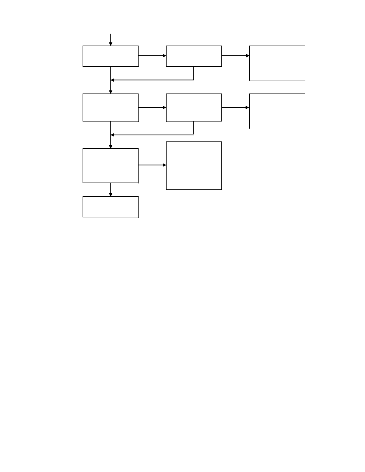
Page 13
10
YES NO
YES
YES
YES
NO
Use With No
Problem.
NO
Due to pulsation
output signal is earily
affected by noise,
operation error may
occur and lead to
failure.
Whether cable used
separates from other
power line.
YES
Whether there is
coolant, oil, air, dust
or others.
Whether there is
protection, such as
cover, for cylinder.
NO
Wear or damage on
sensor, packing, etc.
will lead to failure of
cylinder.
YES
Whether magnetic
field affects the
results.
Whether it is
operated at
environment which
Count will
mulfunction and
control will be out
Thus, lead to failure
of operation.
NO
Page 14
11
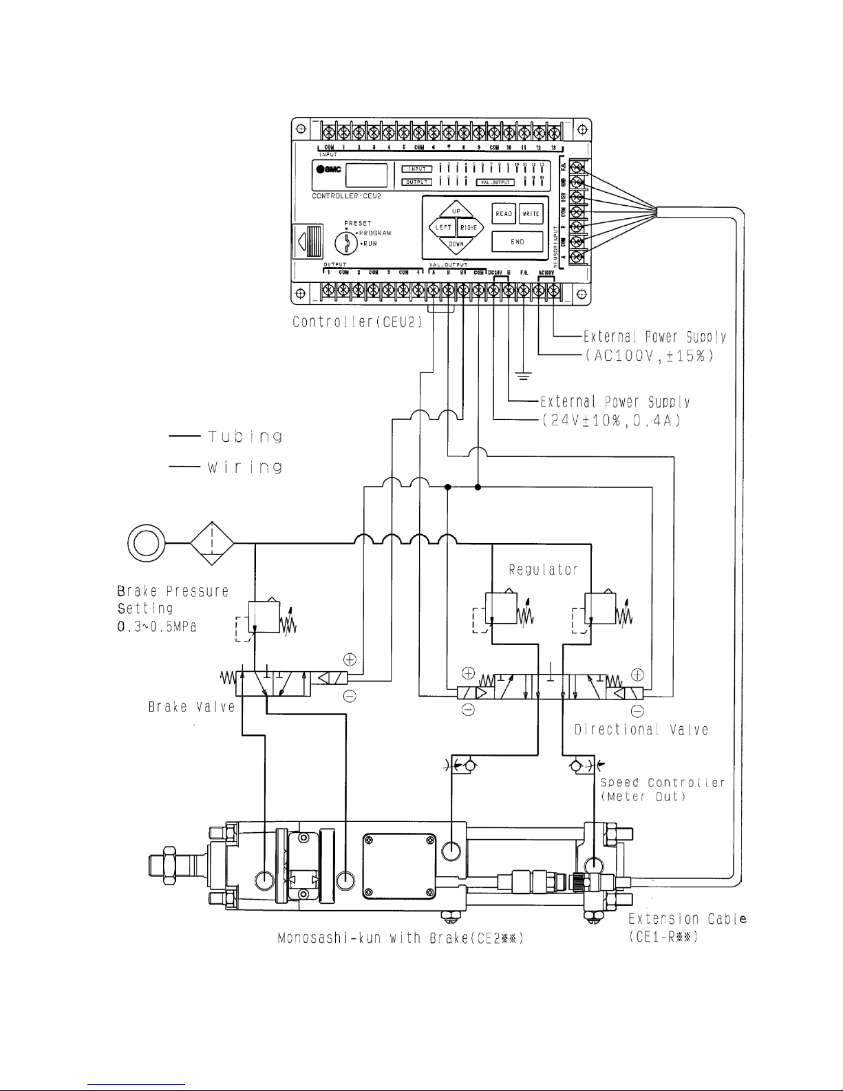
2-2 System Configuration
Page 15
12
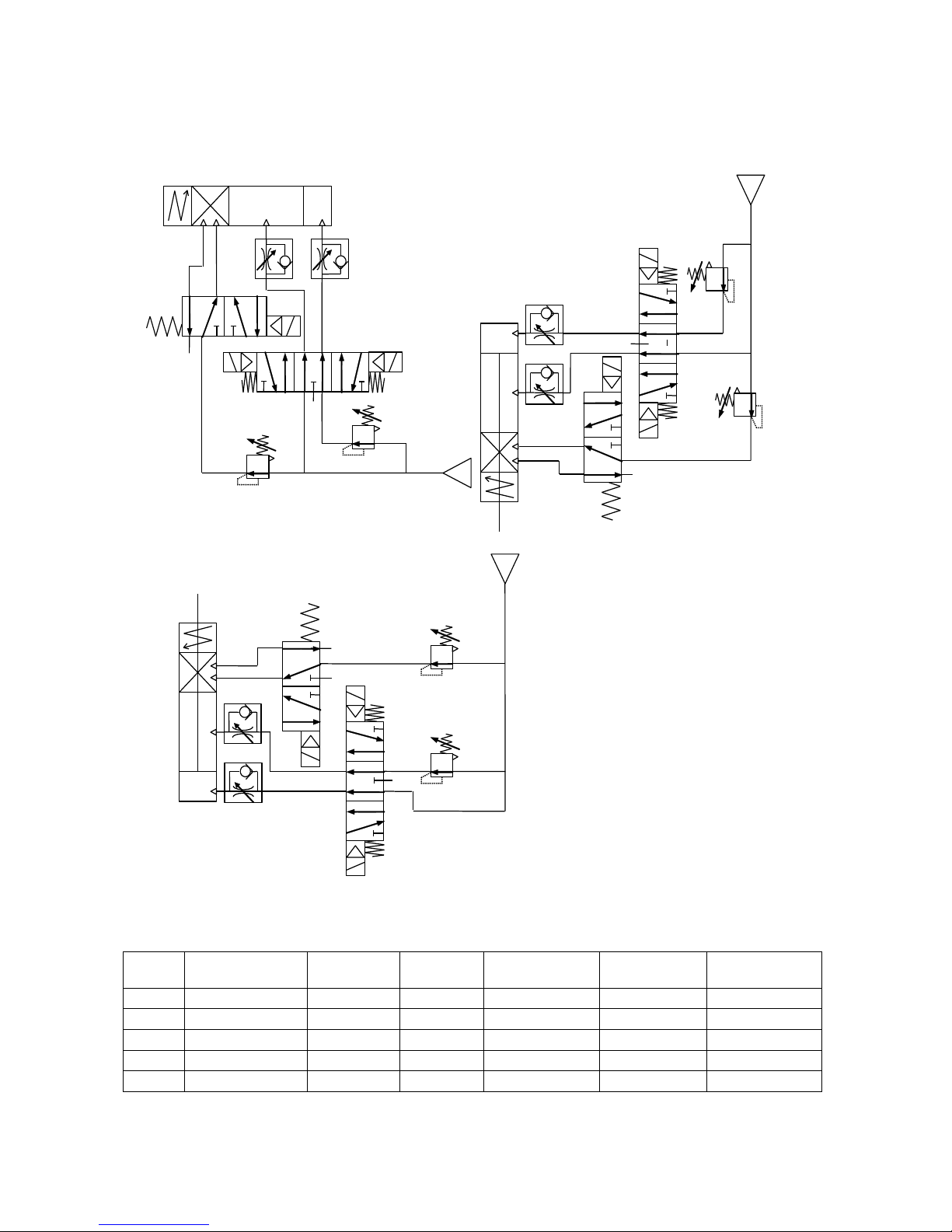
2-3 Recommended Circuit Design
Horizontal Mounting
Downward Mounting
Upward Mounting
<Air Circuit Diagram>
Recommended Pneumatic Equipment
Bore
Directional
valve
Brake
valve
Regulator
Tubing
Silencer
Speed
Controller
φ40
VFS24□0R
VFS21□0
AR425
Nylon φ8/6
AN200-02
AS4000-02
φ50
VFS24□0R
VFS21□0
AR425
Nylon φ10/7.5
AN200-02
AS4000-02
φ63
VFS34□0R
VFS21□0
AR425
Nylon φ12/9
AN300-03
AS4000-03
φ80
VFS44□0R
VFS31□0
AR425
Nylon φ12/9
AN300-03
AS420-03
φ100
VFS44□0R
VFS31□0
AR425
Nylon φ12/9
AN400-04
AS420-04
*Please install the silencer responding to it necessary.
Page 16

13
3. SPECIFICATIONS
3-1 Cylinder Specifications
Bore Size
φ40
φ50
φ63
φ80
φ100
Operating Fluid
Air (Non-Lubricated)
Proof Pressure
Drive Pressure : 1.5MPa Brake Pressure : 0.75MPa
Max. Operating Pressure
Drive Pressure : 1.0MPa Brake Pressure : 0.5MPa
Min. Operating Pressure
Drive Pressure : 0.1MPa Brake Pressure : 0.3MPa
Piston Speed
50~500mm/s
Ambient Temperature
0~60℃
Maximum Stroke (Standard)
850mm
800mm
800mm
750mm
750mm
Brake Type
Integrated Pneumatic and Spring
Sensor Cord Length & Type
φ7-500mm & Oil Resistant
Hardware
JIS B0209
3-2 Controller Specifications
Type
CEU2
CEU2P
Model Nomenclature
Controller
Mounting
Surface Mounting (Din Rail or Screw)
Operating Modes
PRESET・PROGRAM・RUN
Display
Back lighted Display
Position Setting Capacity
1-16 Programs, Each Program 1-32 steps
Position Control Method
PTP(Point To Point)
Control Axes
One Axis
Position Setting Method
Key Input to Controller
Position Setting Range
9999.9mm
Min. Setting Range
0.1mm
Memory
8kbyte Static RAM (5-Year Battery Backup)
Min. Setting Interval
5mm and above
Input Signal
START, GOHOME, PROGRAM#, PAUSE, EMERG, STOP, SETHOME
RESET, AUTO/MANUAL, IN/OUT(Manual mode only)
Output Signal
Move Completed, At Home, Program End, Error
Controlled Output
NPN Open Collector
(DC30V, 50mA)
PNP Open Collector
(DC30V,50mA)
Power Supply
AC100V±15%, 50Hz/60Hz & DC24V±10%, 0.4A
Operating Temp. Range
0℃~50℃
Operating Humidity Range
25%~85%
Shock Resistance
10~55Hz, Amplitude 0.75mm Each Axis for 2 hours
Noise Resistance
Square Wave (1μs Pulse Width)
±1500V at Power Terminal, 600V at Input Terminal
Impact Resistance
10G, 3 times at each axis
Proof Voltage
AC1500V, 1Min(less than 3mA) , between Case & AC Line
AC500V, 1Min(less than 3mA) , between Case & 12VDC
Current Consumption
Below 1.0A
Insulation Resistance
DC500V with Above 50MΩ, between Case & AC Line
Mass
690g
Page 17

14
3-3 Sensor Specifications
Cable
φ7, 6 Core Twisted Pair Shielded Wire
(Oil, heat and flame resistance cable)
(Connector : R03-R8M, Tajima Musen Denki Company)
Max. Transmission Distance
20m (6 core twisted pair shielded wire)
Position Detection Method
Magnetive Scaled Piston Rod & Detection Head
(50cm Cable, Incremental Type)
Magnetive Field Resistance
14.5mT
Power Supply
DC12V~24V±10% (ripple less than 1%)
Current Consumption
50mA(MAX.)
Resolution
0.1mm/pulse
Accuracy
±0.2mm
Output Type
Open Collector (26.4V, 35mA)
Output signal
Phase A & B with Differential Output
Max. Response Speed
500mm/s (Sensor : 1500mm/s)
Proof Voltage
AC500V, 1 min (Case to 12E)
Insulation Resistance
DC500V, above 50MΩ (Case to 12E)
Shock Resistance
33.3Hz6.8G, 2hours at X, Y and 4 hours at Z
JIS D1061 as standard
Impact Resistance
30G, 3 times at each axis
Moisture Resistance
IP-65<IEC STD>
Extension Cable
(Option)
5m, 10m, 15m, 20m
(Connector : R03-P8F, Tajima Musen Denki Company)
Page 18

15
4. MODEL
4-1 Monosahi-kun with Brake
CE2 B 40 100 J
4-2 Controller
CEU2
B Standard
L Plate
F Rod Flange
G Head Frange
C Single Clevis
D Double Clevis
T Center Trunnion
Mounting
40 40mm
50 50mm
63 63mm
80 80mm
100 100mm
Tube Bore
Without Gaiter With Gaiter Without Gaiter With Gaiter
40
25~850 25~700
1200 950
50
25~800 25~650
1150 900
63
25~800 25~650
1150 900
80
25~750 25~600
1100 900
100
25~750 25~600
1100 850
Range of manufacturable stroke
Standard stroke (mm)
Tube Bore(mm)
Standard Stroke
J Nylon Tarpaulin
K Neoprene
None Both Sides
N None
R Cushion at Rod side
H Cushion at Head side
None With connector
Z None
Gaiter
Cushion
Connector
Auto switch’s Type
(Refer to Catalog)
Cylinder Accessories
None 2
s 1
n n
No. of Auto switch
None NPN Open Collector
P PNP Open Collector
Output Method
Page 19

16
4-3 Extension Cable
CE1-R
Length of Cable
Postscript
Connector’s Connection
05 5m
10 10m
15 15m
20 20m
None Extension Cable
C
Symbol Core Wire Color
A White
B Yellow
C , D Brown, Blue
E Red
F Black
G (Shield)
Page 20

17
5. External Dimension Drawing
5-1 Monosashi-kun with Brake
Page 21

18
Page 22

19
5-2 Controller
Page 23

20
5-3 Extension Cable
Page 24

21
6. Part Identification
6-1 Monosashi-kun with Brake
①Piston Rod
②Cover
③Pin Guide
④Rod Cover
⑤Sensor Cover
⑥Cylinder Tube
⑦Tie Rod
⑧Head Cover
⑨Cushion Valve
⑩Connector
⑪Cable
①External Input Terminal
②Sensor Input Terminal
③AC Power Supply Input Terminal
④Earth Terminal
⑤DC Input Terminal
⑥Valve Output Terminal
⑦External Output Terminal
⑧Mode Switch
⑨Dip Switch for Condition Setting
⑩LCD Display
⑪Input Signal Monitor
⑫Input Data Key
1
3 4 7 5 2 6 10
11
8
9
1 2 3 4 5 6 7 8 9
10
11
12
Page 25

22
7. Installation & Wiring
7-1 Installation
7-1-1 Installation of Cylinder
1. During installation of metal fitting onto the end (screw thread) of piston rod, prevent from the
induction of impact and unbalance loading acting upon it.
2. During mounting of cylinder and load, care should be taken not to give misalignment non twist.
Please attach floating joint between the connection.
3. Make sure that pushing force of cylinder act on the centre of load.
4. Do not disassemble cylinder and dismantle sensor from cylinder.
5. Flushing of pipe should be done. Prevent dust & dirt entering into cylinder. Moreover, mist separator
should be used to get rid of water vapor, oil and dirt from the utilized comprised air.
6. When oil is needed to be fed in, use turbine oil class 1 (ISO, VG32).
7. If there is a lot of dust at working environment, use gaiter. Besides that , please take note that
operating temperature should be kept between 0 to 60℃.
8. The total length of air piping (from cylinder to solenoid valve) should be kept below 1m.
7-1-2 Installation of Controller
1. During installation of controller, use M4 bolt and DIN rail.
2. Prevent from direct shining of sun, high or low temperature’s environment.
[Operating temperature range : 0℃~50℃]
3. Do not utilize it at high humidity’s environment.
[Operating humidity range : 25%~85%]
4. Keep it within noise protection material and away from high voltage and power supply wire.
5. Prevent it from mounting in environment containing a lot of dust, salinity, ferrous, or flammable,
corrosive gas.
6. Do not mount it at high vibration and impact environment.
[Proof Vibration : 10~55Hz, range 0.75mm, x, y, z each axis for 2 hours]
7-2 Wiring
7-2-1 The Connection of Power Supply
Power Supply Specification : AC100V±15% (AC85V~AC115V), 50/60Hz
DC24V±10%, 0.4A
Use wire with 0.75mm2 or more in the diameter of wire sectional area and twist it.
FG is meant for preventing lightening strike, use wire, 0.75mm2 or more in the diameter of wire
sectional area, to connect to earth.
If FG is not connected to earth, controller’s noise filter will not be able to function properly. Hence, noise
will be generated and lead to misreading / disoperation of cylinder.
7-2-2 The Connection of Extension Cable
Use specified (SMC) extension cable. Cable length, 5m~20m, with interval of 5m. For distance more
than 20m, use specified transmitter・Receiver box (Model : CE1-H0374)
* Example on cable Connection
Above 20m
Extension Cable
(CE1-R※※)
Page 26

23
* Note
1. Clamp and fix the connector and sensor connection to reduce tension acting on them.
2. Separate cable with power line to prevent from the occurring of noise.
3. When cable is necessary to have U bend, set the bending radius to be above 25mm.
Bending Ability: According to drawing shown below, life span 4 million cycles or more can be achieved.
R25
200m
Reciprocating with
Bending Speed, 100 times/sec
Page 27

24
7-3 Input Signal Wiring
7-3-1 Input Signal Wiring Diagram
Page 28

25
7-3-2 Input Signal Content
Start・・・・・・・・・・・Once started, setting position will be inputted. One step of movement per one shot
(above 50msec).
Note: Start signal (above 50msec’s signal) will be received and activated to carry out
subsequence step, only if homing has been performed and origin signal has been fed
back to controller.
Homing・・・・・・・・When cylinder rod returns to origin, signal above 50msec will be inputted.
Auto / Man’l・・・・When the terminal and COM are in open state, auto mode is on. Vise versa (short circuit),
manual mode is on.
Auto mode・・・・・・When start signal is inputted. Motion will be executed step by step.
Hand mode・・・・・Man’l 1 (terminal 11) or Man’l 2 (terminal 12) and COM is short circuit to
control either moving forward or backward.
Motion direction depends on tubing and wiring.
Pause・・・・・・・・・・・・・During positioning, motion is stopped by this command. When the command is
cancelled, positioning will be resumed from the stopped position.
Note: Please note that Err5 (operating error) will arise, if the stopping position after
pausing is less than 5mm away from setting point.
Emergency Stop・・・・・During positioning, the input of this command will force immediate stoppage of
executing motion. After signal inputs, controller will show error message, Err10.
Note: After emergency stop, homing will perform
Program selection 1,2,3 & 4・・・・・Select program according to following table (Binary Cord): -
Program No.
N Terminal No.
6 7 8 9 1
0 0 0
0
2
1 0 0 0 3
0 1 0
0
4
1 1 0 0 5
0 0 1 0 6
1 0 1
0
7
0 1 1
0
8
1 1 1
0
9
0 0 0 1 10
1 0 0 1 11
0 1 0
1
12
1 1 0
1
13
0 0 1 1 14
1 0 1 1 15
0 1 1 1 16
1 1 1
1
0…Open between IN6~9 and COM
1…Short Circuit between IN6~9 and COM
Set Home・・・・・ When dip switch No.1 is set ON, origin’s signal is inputted. If dip switch No.1 is set to OFF,
auto switch signal input is not required.
・・・・・・・Used at Manual Mode. When signal is inputted, cylinder rod either moves forward or
backward.
External Reset…The input of signal above 50msec will lead to reset of the system. When error occurs,
execute RESET.
Man’l 1
Man’l 2
Page 29

26
7-3-3 INPUT’s Wiring
Input signal consists of 13 signals. With +24V input, +5V is isolated by photo-coupler.
Signal’s name: Start, Homing, Man’l / Auto, Pause, Emergency Stop, Program selection #1,
Program selection #2, Program selection #3, Program selection #4, Set Home,
Man’l 1, Man’l 2 and External Reset.
Input internal circuit is shown below:
7-3-4 OUTPUT’s Wiring
Output signal consists of 4 signals. Together with +5V, photo-coupler is insulated from the 4 output.
Signal’s name: Position Detected, Origin Calculated, Program End, Error
Maximum terminal Voltage: DC +30V
Maximum Current: 50mA (0℃~50℃)
Output Internal’s Circuit
+24V
IN
+5V
10mA
COM
Use current of more than 10mA as input signal.
Model
CEU2
CEU2P
Connection Method
OUT
COM
Load
Controller: CEU2
NPN Output Transistor
Max
DC +30V , 50mA
COM
Load
OUT
PNP Output Transistor
Max
DC +30V , 50mA
Controller: CEU2P
Page 30

27
7-3-5 Solenoid valve’s wiring
Solenoid valve Driving Output consists of 3 signals.
+5v together with photo-coupler is in isolation state.
Signal’s name: Brake, Driving A & B
Maximum terminal’s Voltage +24V DC
Maximum current 80mA (0℃~50℃)
Solenoid Output’s internal Circuit is shown below.
7-3-6 Sequencer
Due to wiring between controller and sequencer, setting of pulse width to be 50msec in program does
not ensure the output pulse width will take the same value, Hence, set the pulse width accordingly, so
as to obtain pulse width of above 50msec, measured from controller.
U
24E
+24V
COM
Valve
driving Output
VAL.OUT
(A、B、BR)
(+)
Valve
(-)
External
Supply
24V DC
24E
Page 31

28
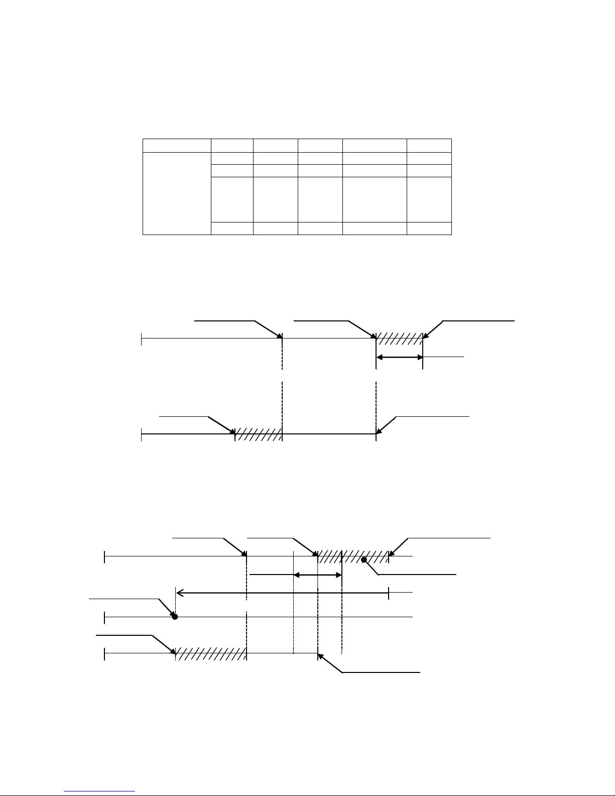
8. Timing Chart
Homing Timing Chart
Note: Homing will be executed only on RUN mode and during automatic executing.
(*1)After resetting and re-supplying power, controller will need 2.0 sec (max) to resume operation.
(*2)Timing from stopping till output is the preset timing t1 (preset data P7).
(*3)Refer to P.27 7-3-6 Sequencer.
(Input)
Reset
Homing
(*3)
SetHome
Man'l / Auto
Start
Program Selection
Man'l (+)
Man'l (-)
(Output)
Driving(+)
Driving(-)
Brake
(*1)
Origin Determined
(*2)
(*2)
Program END
(*1)
Error
Origin
POWER ON
I
N
I
T
I
A
L
I
Z
E
D
MIN50msec
Page 32

29
Automatic Executing’s Timing Chart
Note: After starting, program selection is not valid until program END.
Perform program selection before inputting START signal.
(*1)Timing from stopping till output is 0.2sec (max).
(*2)Refer to P.27 7-3-6 Sequencer.
(Input)
Reset
Homing
SetHome
Man'l / Auto
Start
Program Selection
Man'l (+)
Man'l (-)
(Output)
Driving(+)
Driving(-)
Brake
Origin Determined
(*1) (*1)
Program END
(*1)
Error
Origin
MIN50msec(*2)
Page 33

30
Automatic Execution Timing Chart (Activation of Manual mode during motion)
Note: If Manual mode or Run Mode is activated during Auto Mode, motion will stop.
(*1)Timing from stopping till output is 0.2sec (max).
(*2)Refer to P.27 7-3-6 Sequencer.
(Input)
Reset
Homing
SetHome
Man'l / Auto
Start
Program Selection
Man'l (+)
Man'l (-)
(Output)
Driving(+)
Driving(-)
Brake
Origin Determined
(*1) (*1)
Program END
(*1)
Error
Origin
MIN50msec(*2)
Page 34

31
Manual Executing Timing Chart
Note: During manual operation, Start signal is not effective.
Pressing Man’l (+) and Man’l (-) together will not take effect too.
Despite software determines origin, manual operation will be executed.
(*1) Timing from stopping till output is 0.2sec (max).
(Input)
Reset
Homing
SetHome
Man'l / Auto
Start
Program Selection
Man'l (+)
Man'l (-)
(Output)
Driving(+)
Driving(-)
Brake
Origin Determined
(*1) (*1)
Program END
Error
Origin
Page 35

32
Pause during homing Timing Chart
Note: Homing will be executed, only on RUN mode and during automatic executing.
(*1) Timing from stopping till output is the preset timing t1 (preset data P7).
(*2) Refer to P.27 7-3-6 Sequencer.
(Input)
Reset
Homing
SetHome
Man'l / Auto
Start
Man'l (+)
Man'l (-)
Pause
(Output)
Driving(+)
Driving(-)
Brake
Origin Determined
(*1)
(*1)
Program END
Error
Origin
POWER ON
I
N
I
T
I
A
L
I
Z
E
D
MIN50msec(*2)
Page 36

33
Pause during Automatic Execution Timing Chart
Note: During manual operation, Pause is effective less.
(*1)Timing from stopping till output is 0.2sec (max).
(Input)
Homing
SetHome
Man'l / Auto
Start
Program Selection
Man'l (+)
Man'l (-)
Pause
(Output)
Driving (+)
Driving (-)
Brake
Origin Determined
(*1) (*1)
Program END
(*1)
Error
Origin
Page 37

34
Emergency Stop (Automatic Execution) Timing Chart
Note: When Emergency Stop is set to be ON, error will be also set ON. Vice versa.
Therefore, the display of error does not really show that error output.
Emergency Stop is also effective at Manual mode.
(*1) Timing from stopping till output is the preset timing t1 (preset data P7).
(*2) Timing from stopping till output is 0.2sec (max).
(Input)
Homing
SetHome
Man'l /Auto
Start
Program Selection
Man'l (+)
Man'l (-)
Pause
(Output)
Driving(+)
Driving(-)
Brake
Origin Determined
(*1)
(*1)
Program END
(*1)
Error
(*2)
Origin
Page 38

35
Data Error (Program free of error) Timing Chart
Note: When LCD displays error ON, press ON to clear the error.
Therefore, it is quite different from error output.
Data error will be recognized while the first step is executed.
(*1)Timing from stopping till output is 0.2sec (max).
(*2)Refer to P.27 7-3-6 Sequencer
(Input)
Reset
Homing
SetHome
Man'l / Auto
Start
Program Selection
Program No1 Program No2
Man'l (+)
Man'l (-)
(Output)
Driving(+)
Driving(-)
Brake
Origin Determined
(*1)
Program END
Error
Origin
LCD displays error ON LCD displays error OFF
MIN50msec(*2)
Program No.1 Data Error (or no)
Program No.2 Data Normal (or error)
Page 39

36
9. Data Setting
9-1 Data Presetting
9-1-1 Data Classification & Content
P1―Cylinder Stroke Input stroke.
P2―Tolerance Input positioning tolerance range. Retries will assure the positioning
within the tolerance range.
P3―Retries Input no. of retries. Maximum retries will be 9. Since Err9 (positioning
error) will appear and the system will stop when positioning is not
able to be set within the range, it is advisable to set the max. retries
no.
P4―Bore Size Input cylinder bore size.
P5―Load Rate Input the load rate (the amount of correction for load against the
movement of cylinder rod). Use formula as shown below: -
<Eg.> Bore size: 40(⇒0.04m) Load: 200N (Allowable kinetic Energy)
Operating Pressure: 0.5MPa(⇒5×10⁵Pa)
200 ÷
0.04×0.04×3.14×5×105
× 100 = 31.8 = 30%
4
P6―No. of Brake operation
P7―Origin Detection Time Set the Origin Detection time (t1).
(10ms as 1 unit, maximum will be 9.99s)
After inputting the homing (returning to origin)‘s signal, if sensor does
not receive any signal within t1 (situation whereby the cylinder stops),
this reflects homing is achieved.
Setting of response time should take into consideration of load,
mounting condition, tubing length, etc. The response time should be
re-calibrated. If the operating conditions change.
When controller dip switch No.1, is set at ON, homing will be
confirmed in addition that the auto switch is ON.
P8―Err12 (Operating Error) confirmation time, t2.
*Input Err12’s decision time.
*10msec as 1 unit. Max. will be 9.99sec.
*Within the time frame, if there is no signal feedback by sensor
(cylinder stops) after inputting of start’s signal. Err12 will be reported.
*Setting of the detection time should take into the consideration of
load, mounting condition, tubing length, etc. If the operating
conditions change, re-calibrate the detection time.
9-1-2 Input Method
Turn the controller switching mode to RESET.
P1 will blink.
Load(N) ÷
Bore size(m) × D2 × π × Operating Pressure(Pa)
4
Round-off
PRG
STEP P1
″
″
″
〟
1000.0
Blinking
Page 40

37
Press either READ or WRITE to proceed to the input
condition for cylinder stroke setting. The first decimal
point will start to blink.
Use LEFT and RIGHT buttons to select digit to be
changed and set the digit to the desired setting through
UP and DOWN buttons. With that, input desired cylinder
stroke.
After setting of cylinder stroke, press WRITE to switch
to the next input condition. The display will indicate
PRG STEP P2 and the current tolerance setting. At the
same time, the first decimal point will start blinking.
Next, enter the desired tolerance value as in above
mentioned method.
The maximum possible input value is 9.9mm.
<Reference>
With input of tolerance, 1.0, any point fall between the
set point ±1.0 will be accepted. If the attempt falls
outside the range, retries will perform to get into the
required range.
If the required position is not achieved within the
maximum retries, positioning error (Err9) will be shown.
After setting of tolerance range, press WRITE to switch
to the next input condition. The display will indicate
PRG STEP P3 and the current maximum retries.
Next, enter desired maximum retries.
The maximum possible input value is 9.
PRG
STEP P1
″
″
″
〟
1000.0
Blinking
PRG
STEP P2
″
″
″
〟
1.0
Blinking
PRG
STEP P3
″
″
″
〟
9
Blinking
Setting Point
Tolerance
-1.0
+1.0
1000.0
2
1
9
8
UP
DOWN
RIGHT
LEFT
Page 41

38
During initial setup, predictive control is executing.
Hence, it is suggested to set the maximum retries to
5 or above.
After setting of maximum retries, press WRITE to
switch to the next input condition. The display will
indicate PRG STEP P4 and the current cylinder bore
size, which is blinking.
Next, enter appropriate cylinder bore size.
Setting value will vary as shown below.
Note:
Monosashi-kun with Brake (CE2)’s bore size setting
range from φ40 to φ100.
After setting of cylinder bore size, press WRITE to
switch to the next input condition. The display will
indicate PRG STEP P5 and the current load rate,
which is blinking.
Next, enter correct load rate.
<Calculation>
Load ÷ Cylinder Pushing Force × 100
Setting value will vary as shown below.
After the above setting, press WRITE to switch to the
next input condition.
The display will indicate PRG STEP P6 and the
current number of brake operation
The display number shows the operation number of
brake assembly that had been activated. 1 unit
represents 10,000.
Setting is not required.
PRG
STEP P4
″
″
″
〟
40
Blinking
DOWN
UP
638010025324050
PRG
STEP P5
″
″
″
〟
0
Blinking
DOWN
UP
405001020
30
PRG
STEP P6
0.0
No blinking.
Note:
Change the brake assembly, when
the counter reaches 300.0.
(refer to P.41 11-2)
Page 42

39
After reviewing of number of brake operation, press
WRITE to switch to next input operation. The display
will indicate PRG STEP P7 and present origin
detection time.
Next, enter desired origin detection time. The setting
range is 0~9.99sec (1 unit as 10msec). Set the date
with taking into the consideration of cylinder
operating conditions.
After the above setting, press WRITE to switch to
next input operation. The display will indicate PRG
STEP P8 and present operating error detection time.
Next, enter desired operating error detection time.
The setting range is 0~9.99sec (1 unit as 10msec).
Set the data with taking into the consideration of
cylinder operating conditions.
After the above setting, press WRITE to end the
whole preset operation.
9-1-3 Confirmation of Set Data
Turn the controller switching mode to PRESET.
PRG
STEP P7
″
″
″
〟
200
Blinking
PRG
STEP P8
″
″
″
〟
Blinking
200
PRG
STEP P1
″
″
″
〟
1000.0
″
″
″
〟
UP
DOWN
P1P2P3P4P8P5P6
P7
When P1 is blinking, use UP & DOWN key to
reconfirm each and individual preset value.
When the input value is blinking, press READ
once to shift the operation back to P1.
Page 43

40
9-2 Program Setting
Input desired cylinder positions.
9-2-1 Input Method
Turn the controller switching mode to PROGRAM.
Note:
Step 0 for every program is END.
Program no. “1” will start blinking.
Set the program no. through UP & DOWN buttons.
Program No.
, 1 , 2 , ・・・・・・・・・・・, 15 , 16
After above setting, press WRITE to end the
operation. Step “0” starts to blink.
Next, press either READ or WRITE to proceed to
next stage.
The display “End” will be replaced by “0000.0”,
leading to the input STEP 1.
Input first setting position into STEP 1.
Then, press WRITE to proceed to STEP 2.
Set the following setting positions.
STEP by STEP.
After inputting the last data into last STEP, press
WRITE, and then END to end the program setting.
Note:
Controller will show Err7 during operation, if END is
not inputted at the end of program.
With above mentioned inputting steps,
input program shown below: -
PRG 1
STEP 0
End
″
″
″
〟
Blinking
PRG 1
STEP 1
″
″
″
〟
0000.0
Blinking
PRG 1
STEP 2
″
″
″
〟
0000.0
Blinking
PRG 1
STEP 0
End
″
″
″ 〟 点滅
UP
DOWN
Page 44

41
<Input example>
Turn the controller switching mode to PROGRAM.
Press WRITE 2 times.
The display “End” will be replaced by “0000.0”,
leading to the input STEP 1.
Press LEFT 2 times.
Blinking is shifted to “0”, the first decimal point.
Press UP 5 times to set value of 5.
Press WRITE one time.
Press LEFT 3 times to shift the blinking cursor.
Press UP 3 times to set the value of 3.
Program
Step
S1 50.0 68.0
S2 300.0 30.5
S3 30.0
S0 End End
P1
P8
PRG 1
STEP 0
End
″
″
″
〟
Blinking
PRG 1
STEP 1
″
″
″
〟
0000.0
Blinking
PRG 1
STEP 1
″
″
″
〟
0050.0
Blinking
PRG 1
STEP 2
″
″
″
〟
0000.0
Blinking
PRG 1
STEP 2
″
″
″
〟
0300.0
Blinking
Page 45

42
Press WRITE one time.
Press LEFT 2 times to shift the blinking cursor.
Press UP 3 times to set the value of 3.
Press WRITE one time to enter into program STEP
4, which is the end of program 1.
Press END to end the program setting for program
1.
Program 1’s programming ends.
Set the program no. to 8 through UP to PRG “8”.
Press WRITE 2 times.
The display “End” will be replaced by “0000.0”,
leading to input STEP 1.
PRG 1
STEP 3
″
″
″
〟
0000.0
Blinking
PRG 1
STEP 3
″
″
″
〟
0030.0
Blinking
PRG 1
STEP 1
0050.0
″
″
″
〟
Blinking
PRG 1
STEP 4
″
″
″
〟
Blinking
0000.0
PRG 1
STEP 1
0050.0
″
″
″
〟
Blinking
PRG 8
STEP 0
End
″
″
″
〟
Blinking
PRG 8
STEP 1
″
″
″
〟
0000.0
Blinking
Page 46

43
First, press LEFT one time.
Next, use DOWN to set the value of “8”.
Press LEFT one time.
Then, use DOWN to set the value of “6”.
Press WRITE one time.
Press UP 5 times to set the value of “5”.
Press LEFT 2 times.
Press UP 3 times to set the value of “3”.
Press WRITE to enter input STEP 3, which is the
end of program 8.
Press END to the program setting for program 8.
Program 8’s programming ends.
9-2-2 Confirmation of Input Data
Turn the controller switching mode to PROGRAM.
When PRG “1” is blinking, use UP & DOWN to
select desired program to be checked.
Next, press READ to proceed to the specified
program’s STEP “1”.
Then, use UP & DOWN to check and confirm every
step.
PRG 8
STEP 1
″
″
″
〟
0068.0
Blinking
PRG 8
STEP 2
″
″
″
〟
0000.0
Blinking
PRG 8
STEP 2
″
″
″
〟
0030.5
Blinking
PRG 8
STEP 3
″
″
″
〟
0000.0
Blinking
PRG 8
STEP 1
0068.0
″
″
″
〟
Blinking
PRG 1
STEP 1
0050.0
″
″
″
〟
Blinking
Page 47

44
9-3 Selection of Dip Switch
No.1・・・The Identification of Origin
OFF・・・・When cylinder stops, if there is no signal feedback from sensor within t1 (Preset data,P7),
counter value will be reseted to “0” and origin is obtained / recognized.
Generally, origin will be at the stroke end.
If origin is set within the stroke, install stopper with respect to the origin.
ON・・・・・When the cylinder stops at origin, situated at the location where auto switch or limit switch
is, and sensor signal is not feedback within t1, counter value will be reset to “0.0” and
origin is obtained.
Install the origin wire to terminal 10.
No.2・・・The Setting of Braking System
OFF・・・・In this state, ON means brake is activated. OFF means brake is in releasing state.
If power supply of controller is cut off, the brake will be in releasing state.
If cylinder is mounted horizontally and the air balance is not achieved, when power is cut
off, the cylinder may keep moving in and out.
If cylinder is mounted vertically, when power is cut off, cylinder rod will fall to the bottom
end, due to its own weight.
ON・・・・・In this state, OFF means brake is activated, ON means brake is in releasing state.
If power supply of controller is cut off, the brake will be in clamping state.
Note: Please take note at piping, which may lead to opposite setting.
No.3・・・The Change of Counter Direction
OFF・・・・The extend direction will be an increment on counter.
The origin is set to be at the retract end.
ON・・・・・The retract direction will be an increment on counter.
The origin is set to be at the extend end.
Note: Please take note at wiring as it may result to opposite
setting.
No.4・・・Delection of Memory: Delete all the input data, back to the initial state.
Generally, set the state to OFF. If input data is required to be deleted, set the state to ON. Next,
reset the power supply through terminal 13. After achieving the initial state, set the state back to
OFF.
10. Driving
10-1 Setting of Origin Direction
Location’s detection method used by Monosashi-kun with brake cylinder is incremental method. Please
set the origin and reference accordingly.
Cylinder stroke end, either extend end or retract end, will be the origin. When dealing with cylinder with
cushion, please do not over monitoring the cushion effect.
When stopper is used, please use shock absorber to prevent from the occurrence of impact and “spring
back” effect.
Retract End
Extend
Extend End
Retract
Page 48

45
10-2 Adjustment of Air Balance
Due to the stoppage precision, the rate of occurring of abnormal operation, etc. Will be greatly affected
by the stability of air flow. Please monitor closely to achieve air balancing of cylinder.
Adjustment
1
Manually operate the controller or directional valve & brake valve to shift the piston rod to the center of
stroke.
2
Release the brake and carry out adjustment through pressure reducing valve. Remember, piston rod
should not move during adjustment. Release the brake through brake valve or controller dip switch
No.2.
3
After completion of the adjustment, manually operate brake valve to release and lock the brake system
for a few times. If piston rod is moving during operation, redo the adjustment.
4
Lastly, check it with testing the attainment of desired location.
If piston rod moves to the extreme end or with extraordinarily speed, redo the above adjustment.
Note: If the braking assembly unit has been changed, reset the controller.
11. Error Messages & Countermeasures
11-1 Controller
Err1: Sub-CPU’s ROM, RAM Error
Content
: During power supply to sub-CPU is on, ROM or RAM is found faulty.
Solution
: Reset & Retry.
Countermeasure
: After resetting, if error occurs again, ROM. RAM may have faulty. Change
ROM.RAM.
Err2: Main-CPU’s ROM, RAM Error
Content
: During power supply to sub-CPU is on, ROM or RAM is found faulty.
Solution
: Reset & Retry.
Countermeasure
: After resetting, if error occurs again, ROM. RAM may have faulty. Change
ROM.RAM.
Err3: Battery Error
Content
: During initial checkout, battery voltage less than 3.2V.
Input data can only be retained within 2 hours after the error detection.
Battery’s life is 5 years from the purchasing data.
Solution
: Press ON (UP & DOWN).
Countermeasure
: Change battery. After changing, verify input data. If data has been deleted,
re-input. After resetting, operation of cylinder is still possible.
However, during operation. LCD display will show that “PRG” is blinking. With
the power supply ON, data can be retained as long as 2 hours, after the error
massage appears. Therefore, do not cut off power supply, even during
interchanging of battery.
[Replacement in Japan]
The part No. of the replacement battery assembly is CEU2-H0125.
Please refer to the Battery assembly replacement procedure CE*-OMM0038-*
for replacement. Or please prepare a battery equivalent to the following
conditions and purchase a replacement battery holder assembly
(Part No.: CEU2-H0446) from SMC.Please refer to the Battery assembly
replacement procedure CE*-OMU0014-* for replacement.
[Replacement outside Japan]
Please prepare a battery equivalent to the following
conditions and purchase a replacement battery
holder assembly (Part No.: CEU2-H0446) from SMC.
Please refer to the Battery assembly replacement
procedure CE*-OMU0017-* for replacement.
Battery specifications
- Type: Lithium thionyl chloride battery
- Nominal voltage: 3.6 V - Capacity: 2600 mAh
- Size: Refer to the figure on the right.
<Example>
SAFT lithium battery part number LS14500
Page 49

46
Err4: Backup Error
Content
: After power supply is on or Reset signal is inputted, backup checking is
conducted, error is detected during output. Each and individual data is
checked through backup checking. Once, error is detected, clear the error and
at the same time, data will be deleted too.
Err41・・・Preset Data Error
When this error appears, input data will be deleted. Re-input is
required.
Err42・・・Program Data Error
When this error appears, input position’s data will be deleted.
Re-input is required.
Err43・・・Learning Data Error
When this error appears, learning data will be deleted and lead to
the operation of predictive control (retries will perform again).
When errors appear, re-entry of data is required.
Solution
: Press ON (UP or DOWN).
Countermeasure
: Check below 5 points and execute accordingly.
1
Check whether reset is executed during the execution of controller or during
motion.
Besides that, please verify wiring and sequence of the program.
2
Verify whether AC100V’s deviation is within the tolerance level,
±15% (AC85~115V).
3
Verify the power supply (AC100V) has been toggled within 20ms.
4
Check whether controller’s FG (frame ground) is being connected to earth.
5
Verify that there is no moving signal feedback from sensor while the power
is being cut off.
Err5: Data Error
Content
: 1
During presetting of data, over stating the cylinder’s stroke, or under
stating the moving distance of cylinder (less than 5mm), error will be
shown.
2
During operation, error will also appear, when moving distance is less
than 5mm. However, if the stop position is still within the tolerance of next
setting point, stop point will be determined and accepted.
<Example>
After inputting start, cylinder will stop at the position.
Solution
: During programming, press ON (UP or DOWN).
During moving state, press either ON or RESET.
Countermeasure
: If situation 1 and 2 occur, please change the program accordingly.
Err6: Learning Error
Content
: The stopping position is before the braking position.
50
Setting Point
Next Setting Point
57
Tolerance±4.0
Cylinder Stopping Position 53.1
Stop within the range
Tolerance±4.0
Page 50

47
There is no braking point within the moving distance.
Solution
: Reset or re-providing power supply.
Countermeasure
: Verify air balancing.
Verify whether there is any impact or momentum acting upon cylinder during
positioning. Verify that there is no entanglement or twisting.
Due to the momentum at the stroke end, setting of “0.0” as origin will lead to
high occurrence of errors.
Therefore, set the origin within “1.0~5.0”. Besides that, it is advisable to make
sure that cylinder rod should return to origin at the end of operation.
For cylinder with cushion, due to drastical change of speed within the stroke,
learning error may arise.
Therefore, for the case of stopping position within 30mm from stroke end is
required, it is advisable not to utilize cylinder with cushion.
Err7: No Program
Content
: There is no program being selected.
Program NO., which does not have any contents, is selected.
Solution
: Press ON or Reselect program.
Countermeasure
: Verify input.
Verify selected program, wiring or sequence of program inputted.
After the occurring of Err42, program will be deleted.
Please re-enter program.
Err8: Homing Error
Content
: When dip switch No.1 is set ON, error will show if homing is not performed.
When cylinder stops and limit switch at origin is still ON, homing will be
detected.
Solution
: Reset or Retry.
Countermeasure
: Ensure the origin detection switch is functioning (switch is on when cylinder
rod is at origin).
Ensure wiring is connected properly.
Ensure input signal sent by auto switch is fed to terminal 10 through input
monitor (red LED).
Ensure there is no twist at guide.
During the movement of cylinder rod, ensure that it will not stop within origin
detection time.
Err9: Positioning Error
Content
: Accurate positioning was not performed within specified preset retries (Preset
Data, P3) or preset tolerance (Preset Data, P2).
When Err9 occurs, there are 2 possibilies of errors.
First error due to Err9. Secondly, it may due to abnormal stoppage position.
Recognize the errors, so as to execute accurate remedy.
Stopping Point
Braking Point
Setting Point
Next Stopping Point
Braking Point
Stopping Point
Page 51

48
Solution
: Press either ON or RESET.
When ON is used to remedy situation, next program step will be executed.
However, Err5 will occur if the stopping position when Err9 occurs, is less than
5mm away from the next program step’s specified value. In this case, homing
should be done. Restart the program.
When RESET is used, homing will be performed and operation will go back to
initial state, program step No.1 and restart.
Countermeasure
: Ensure there is no variation on load or pressure.
Ensure air balance state. Ensure there is no twist at guide.
Ensure there is no momentum and impact acting on cylinder while positioning
is performed.
Err10: Emergency Stop
Content
: Display shows emergency stop.
Solution
: Disable the emergency stop signal.
Err11: Processing Error
Content
: Processing error by Sub-CPU is detected.
Solution
: Reset or Retry.
Countermeasure
: If error re-occurs, change the controller.
Err12: Operating Error
Solution
: Press either ON or RESET.
Countermeasure
: Ensure there is no twist at guide.
During the movement of cylinder rod, ensure that it will not stop within
operating error detection’s time. Re-adjust operating error detection’s time.
11-2 Brake Unit’s Life Span
Change the brake unit, when life span of 2 million cycles has been achieved. Check its life span
through the following method: -
a Check the lock pin’s check gap dimension.
b Check through controller preset data (P6), which records the brake’s operation cycle No.
*Check the lock pin. When check gap, L, is 1mm or less, change brake unit
*Check the controller. When the value of 200.0 is reached, change brake unit.
The 2 million cycle life span assumes following conditions:
a Piston speed : 300mm/sec
b 50% load or less when horizontally mounted.
c 35% or less when vertically mounted.
(Within allowable kinetic energy range.)
PRG
STEP P6
200.0
L
Pressure lock port
Lock release port
Page 52

49
12. Appendix
12-1 Data Sheet
●Parameter
Preset Data Dip Switch Setting
●Program Data (Determined Position Data)
No. Data Name
P1 Cylinder Stroke
P2 Tolerence
P3 Retries
P4 Bore Size
P5 Load Rate
P6
No. of Brake Operation
P7
Origin Confirmation Time
P8
Err12's Confirmation Time
No. Setting
No.1
OFF ON
No.2
OFF ON
No.3
OFF ON
No.4
OFF ON
Program
Step
1
2
3
4
5
6
7
8
9
10
11
12
13
14
15
16
17
18
19
20
21
22
23
24
25
26
27
28
29
30
31
32
5678123
4
Page 53

50
Program
Step
1
2
3
4
5
6
7
8
9
10
11
12
13
14
15
16
17
18
19
20
21
22
23
24
25
26
27
28
29
30
31
32
9101112131415
16
 Loading...