

SMC Networks CBW1026, CBW1026LS, CBW1026LLS, CBW1026C, CBW1026LC General Specifications
...Page 1
Schlyer Machine
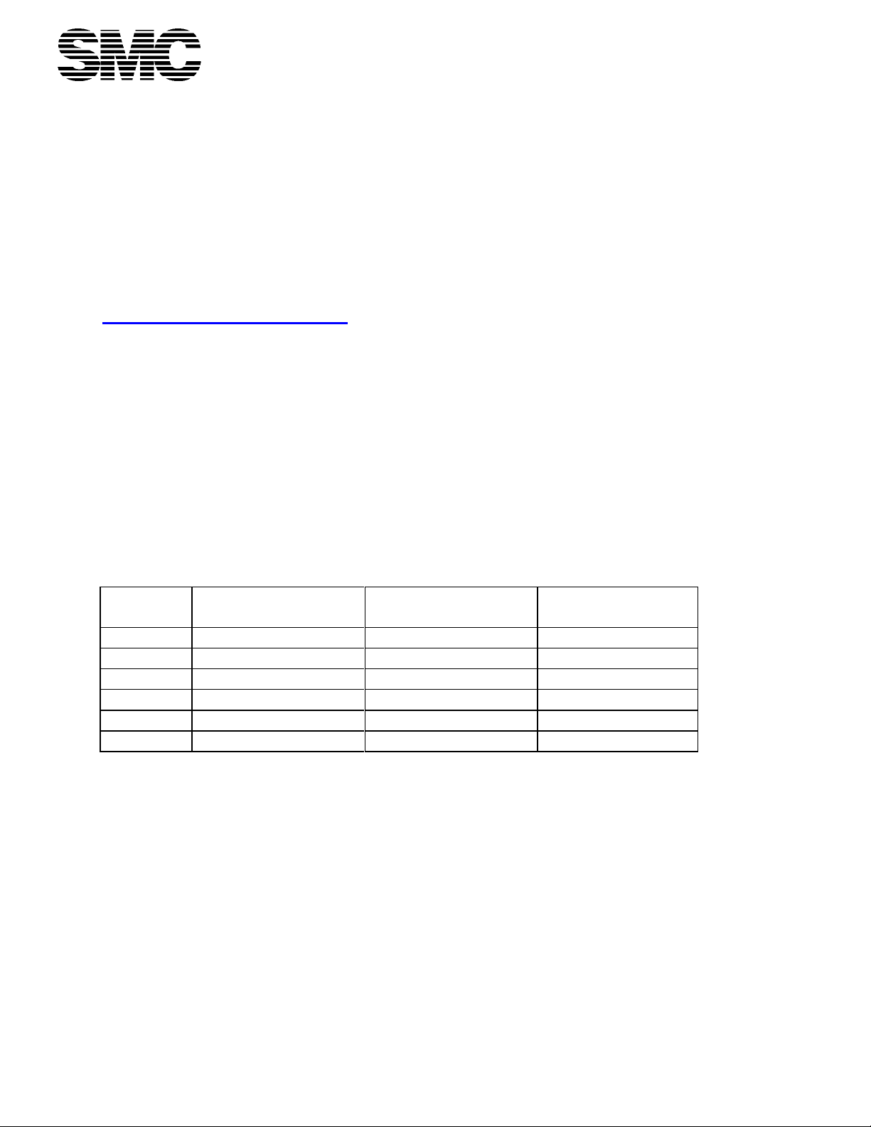
MODEL
DOOR
CONFIGURATION
CHAMBER SIZE*
EXTERNAL
OVERALL SIZE
1026
VERTICAL LIFT
48" X 32" X 34"
72" X 78" X 38-1/2"
1026L
VERTICAL LIFT
48" X 32" X 48"
72" X 78" X 52-1/2"
1026LS
LOAD SHELF
48" X 32" X 34"
72" X 78" X 38-1/2"
1026LLS
LOAD SHELF
48" X 32" X 48"
72" X 78" X 52-1/2"
1026C
CABINET
48" X 32" X 34"
72" X 78" X 38-1/2"
1026LC
CABINET
48" X 32" X 48"
72" X 78" X 52-1/2"
Division of Audubon Machinery Corporation
814 Wurlitzer Drive
North Tonawanda, NY 14120
Toll Free (866) 867-7660
fax: (716) 696-3174
http://www.schlyermachine.com
Model CBW1026 Cage and Bottle Washer
General Specifications
1.0 General Description
The Model CBW1026 Cage and Rack Washer is a high capacity spray cabinet washer
capable of processing any items which can be placed inside the washing compartment. It is
specifically designed to clean and sanitize animal cages, bottles, pans, and other items ancillary to
the care of laboratory animals. Several sizes are available, as well as many optional features. The
Model CBW1026 incorporates a large number of innovative and unique features to ensure
thorough, efficient cleaning, as well as many features unique to our design.
2.0 Dimensions
(W”X H” X L”) (W”X H” X L”)
*Note: Dimensions are maximum chamber opening sizes. Actual load size must be smaller to
allow for clearances. Custom chamber sizes can be provided as required.
3.0 Reciprocating Spray Headers
3.1 Vertical and horizontal headers, surrounding the load, shall be supplied and equipped with
machined jets. Jets shall deliver an elliptical spray pattern for optimal impact and coverage to the
load. No rotating spray arms shall be utilized.
3.2 Headers shall be interconnected and mounted to a carriage having non-lube wheels
constructed from single pieces of Delrin® homopolymer.
SMC Model 1026 Engineering Specification Rev. 100812 Page 1 of 12
Page 2

3.3 Carriage shall be moved reciprocally from end to end within the cabinet by a nonproprietary pneumatic device. No electric motors, gearboxes or cable capstans shall be used.
3.4 All cable sheaves shall be Delrin® homopolymer with Stainless Steel axles.
3.5 Failure of the header system to traverse the machine interior within the allotted time shall
result in a Fault Condition. (Blocked Header; see par. 6.5.3)
4.0 Self-Flushing Debris Strainer
4.1 All treatment solutions shall be pumped through a specially designed strainer that ensures
that the spray jets shall not be plugged by entrapped debris.
4.2 Strainer shall be designed with orifices significantly smaller than those in the jets, such that
debris that is suspended in the treatment fluids and which could lodge in the jet orifices shall be
trapped prior to delivery to the header system.
4.3 After each treatment phase any particles that have been trapped are flushed to drain.
4.4 Drop screens, which are subject to overflow and subsequent failure, and which continue to
expose refreshed treatment fluids to previously entrained debris, shall not be acceptable.
4.5 Strainer shall be easily removable with no tools via a sanitary-style clamp. System shall be
completely self-regulating and require routine inspection and maintenance no more than once per
week under typical operating conditions.
5.0 Automatic Temperature Regulation and Guarantee
5.1 The Final Rinse or Wash Phases shall be selectable as Guaranteed Temperature Phases.
5.2 Timing of a Guaranteed Temperature Phase shall not begin until the solution temperature
has reached the set point (typically 180F or higher), thus ensuring that the load has been subject to
the proper temperature for the entire time set.
5.3 Failure of any Guaranteed Temperature Phase to reach the setpoint temperature within the
allotted time shall result in a Fault Condition. (Temperature Failure; see par. 6.5.4)
6.0 Safety and Certifications
6.1 An OSHA-style Emergency Stop button shall be installed on the operator control panel.
This switch shall be hard-wired to a safety stop relay, which when de-activated shall interrupt all
power to the outputs of the machine, thus satisfying the Dept. of Labor, Occupational Safety and
Health Administration standards for industrial machinery.
6.2 A Magnetic safety switch(es) on the door(s) shall reliably ensure that all treatments stop
instantly if the door(s) is opened.
SMC Model 1026 Engineering Specification Rev. 100812 Page 2 of 12
Page 3

6.3 All outputs external to the electrical box shall be low voltage DC, Intrinsically Safe by
the definition of OSHA and National Electrical Code (NEC).
6.4 All devices and components that consume electrical power shall be UL listed and/or
approved, and shall bear NEMA (US Standards), IEC (International Standards) or other
recognized International ratings appropriate for the use intended. The control assembly shall be
produced in a UL Panel Shop and shall be UL listed.
6.5 Fault Conditions shall be annunciated on the operator interface screen, and shall be sent
to the RS232 interface port or the Ethernet port for printing and/or data acquisition. At least five
(5) fault conditions shall be so identified.
6.5.1 Emergency Stop - Depression of the Emergency Stop Button shall reset the
machine and display a fault message that identifies the source of the emergency stop
signal.
6.5.2 Door Open - Lack of positive door closure shall cause the machine to enter Pause
mode, from where the current cycle can be recovered. Fault message shall indicate which
door is at fault, if the machine is so equipped.
6.5.3 Drive Blocked - Failure of the drive to traverse the cabinet in the time allowed
shall cause the machine to enter Pause mode and shall cause the screen to display the
Drive Blocked message.
6.5.4 Sump Heat - Failure of the sump to reach the desired temperature in the expected
time shall cause the machine to enter pause mode and shall cause the screen to display the
Sump Heat Fault message.
6.5.5 Fill Fault - Fill Fault message shall be displayed and Pause mode shall be entered
whenever the sump fails to fill in the allotted time.
7.0 Pneumatically Operated Valves
7.1 All automatic ball valves shall be controlled by pneumatic operators. Electric-motor-
operated ball valves shall not be acceptable.
7.2 All automatic water and steam control valves shall be direct-operated pneumatic types.
Pilot-operated solenoid valves or any valve that incorporates a diaphragm-type sealing system
shall not be acceptable.
SMC Model 1026 Engineering Specification Rev. 100812 Page 3 of 12
Page 4

8.0 Microprocessor Control
8.1 The treatment schedule and all other machine functions shall be controlled by a readily
available, non-proprietary, industrial style modular Automation Direct 205 Series programmable
controller. The controller and all modules shall be readily available and technical support shall
be available from the PLC manufacturer at no charge, without any need to pay any fee to stay in
product support.
8.2 Module replacement for the I/O system shall be easily accomplished with no tools and no
wiring disconnection or connection.
8.3 The control system shall be programmed in simple ladder logic.
8.4 A 6” C-More Color Touch Screen shall provide complete operator interface, diagnostic
and programming capability. No special skills or knowledge shall be necessary to set up and
control all machine functions. No Touch Screens less than 6” shall be used.
8.5 Diagnostics shall be available from the Color Touch Screen, which will allow direct
access to all I/O points for complete diagnosis of all machine systems.
8.6 Treatment schedules and cycle phase selections shall be programmable from the Color
Touch Screen. PIN screens shall be available at the discretion of the supervisor to lock out access
to the cycle phase programming functions. All timers in the program, as well as all cycle phase
temperatures, shall be accessible and settable through the operator interface screen, with no
necessity for the connection of either an auxiliary programming device or a modem/telephone
line connection.
8.7 All controls shall be of industrial design and type, in order to resist the extreme
environmental demands of the washroom. All electrical wiring, operator interface controls and
circuits shall be protected in accordance with NEMA, UL and NEC standards.
9.0 Insulated Exterior
9.1 The exterior of the machine shall be insulated with rigid insulation. This insulation shall be
an integral part of the machine, designed to maintain the high temperatures required in the washing
chamber and to limit radiation loss to the surrounding air.
10.0 Manuals & Documentation
10.1 A full set of manuals explaining machine operation and PLC operator controls shall be
provided.
10.2 A hard copy of the PLC ladder diagram shall be available at no additional charge. Like
all component parts, the Software for the unit shall be Non-Proprietary and available to the
customer as a technical support function at all times and forever.
SMC Model 1026 Engineering Specification Rev. 100812 Page 4 of 12
Page 5

10.3 A complete list of purchased parts including original part numbers, where the parts were
purchased, and the nearest local distributor where the parts can be purchased shall be provided as
a standard part of the manual. All purchased machine components such as jets, valves, PLC
modules, pneumatic system parts, etc., shall be entirely non-proprietary and available for
purchase freely and widely through normal industrial supply outlets.
20.0 Machine Operation
20.1 Items to be cleaned shall be placed inside the cabinet by the operator. The door shall be
closed and the pre-programmed treatment cycle phase options chosen. Treatment shall commence
and continue automatically to the end of the cycle. Once the treatment cycle is complete, the
operator shall open the door and remove the cleaned items.
20.2 All cycle phase selections and other cycle options shall be available for selection from the
Color Touch Screen, with supervisory PIN screens preserving security of cycle parameters.
Machine memory shall allow storage of a minimum of four(4) distinct cycles, to be recalled through
simple screen selections. Names or descriptions for each saved treatment program shall be available
for edit using the Supervisor PIN code. All cycle selections shall be easily customized by
supervisory personnel from the Screen.
20.3 Standard cycle phases shall include at least the following general treatment options:
20.3.1 Pre-rinse - Water retained in the sump from the last rinse shall be used to remove
heavy soil, flushing any easily removed matter to drain in order to ensure that the detergent
solution stays as clean as possible. Treatment shall be under pressure from the main
treatment pump at 230 GPM @ 80 feet of head. At the end of this cycle phase, debris
entrapped by the self-flushing strainer shall be sent to drain with the used treatment water.
20.3.2 Wash - Fresh hot water from the customer's supply shall be used to fill the sump,
with detergent being introduced by dispenser or manually during filling. When the sump is
full, heating shall begin in order to bring the wash solution up to the desired temperature.
The wash treatment shall be under pressure from the main treatment pump at 230 GPM @
80 feet of head. At the end of the wash cycle, detergent solution shall be flushed to drain.
The self-flushing debris strainer shall be cleaned in the process of draining the sump,
sending any entrained debris to the sewer immediately.
20.3.3 First Rinse - Fresh hot water from the customer's hot water supply shall fill the
sump, and shall be circulated through the jet system by the main treatment pump at 230
GPM @ 80 feet of head. The heating system shall be active during this cycle, maintaining
the temperature of the rinse water. At completion, the used water shall be conducted to
drain, flushing the strainer in the process.
20.3.4 Final Rinse - Fresh hot water from the customer's hot water supply shall fill the
sump, and shall be circulated through the jet system by the main treatment pump at 230
GPM @ 80 feet of head. The heating system shall be active during this cycle, maintaining
the temperature of the rinse water. At the election of the operator, this treatment cycle phase
SMC Model 1026 Engineering Specification Rev. 100812 Page 5 of 12
Page 6

shall utilize the temperature guarantee circuitry. In this case, timing of the cycle phase shall
not begin until the rinse water is recirculating at the setpoint temperature, thus guaranteeing
appropriate sanitation. At completion, this rinse water shall be retained in the sump for use
as pre-wash water for the next load.
20.3.5 Exhaust - When all wet cycle phase treatments are complete, the automatic exhaust
damper shall open and any residual vapor in the cabinet shall be vented to the customer's air
handling system. The time allowed for this ventilation shall be determined by experience
with the specific application and subsequent adjustment of the user program through the
operator touch screen.
30.0 Details of Construction
30.1 General
30.1.1 All wetted parts shall be of Type 304 Stainless Steel or appropriate polymeric
materials.
30.1.2 All electrical assemblies, piping assemblies and mechanical apparatus shall be
designed for, and be appropriate for use in, a high temperature sanitary wash-down
environment. All components shall be selected for their ability to perform for long periods
of time in the adverse and high production environment of the laboratory washroom. Each
purchased part and each engineered part and sub-assembly shall be scrutinized and all
specific design decisions shall be made in the light of these basic criteria.
30.1.3 All purchased components shall be un-modified, off-of-the-shelf items available to
the owner in his locality, should he need them.
30.1.4 Original manufacturers' part numbers and descriptive information for all purchased
parts shall be made an integral part of the service manual information provided at time of
installation. Every effort shall be made throughout the life of the machine to assist the owner
in acquiring any parts needed.
30.2 The door(s) of the washer shall be of double-walled stainless steel construction, filled with
insulation. Door safety switches shall ensure that the machine cannot operate with the door(s) open.
Tempered Safety Glass windows shall be provided in any doors to allow visual inspection of the
interior with the door(s) closed. Machine shall be equipped with a fluorescent strip light assembly,
which shall be mounted outside the machine above the roof. A tempered glass window shall be
placed in the roof panel to allow light from the fixture to enter the machine. Lights mounted interior
to the machine shall not be acceptable.
30.3 A stainless steel load grid shall be supplied to support all loads.
30.4 The recirculating sump shall be equipped with a stainless steel steam coil, fully welded in
accordance with ASME Section VIII and fabricated from Stainless Steel materials designed to carry
SMC Model 1026 Engineering Specification Rev. 100812 Page 6 of 12
Page 7

steam at the rated pressures. No structural-style parts will be acceptable. The coil shall be easily
Item
Material
base and sump
12 gauge, 304 SS - #3 finish
door panels
16 gauge, 304 SS - #3 finish
side and top panels
14 gauge, 304 SS - #3 finish
recirculating piping
304 SS
spray header and jets
304 SS
recirculating pump housing and impeller
Stainless Steel
recirculating valves
Stainless Steel
external water piping
copper
steam coils
Sch 40. 304 SS - #2B finish
removed for cleaning or maintenance. Under no circumstances shall the coil be welded into place.
30.5 Temperature shall be controlled directly by the PLC. Temperature sensor(s) shall be Type J
Thermocouples, connected directly to the analog inputs of the PLC.
30.6 Steam controls shall be included for 30-80 psi dry steam. No diaphragm-type steam valves
shall be acceptable. Condensate trap(s) shall be disc/thermodynamic type only.
30.7 Water level shall be maintained by an electronic level control with removable and easily
cleaned probes. Probes shall be removable for cleaning with no tools required, such as with a
sanitary-type clamp fitting.
30.8 The treatment pump shall be a horizontal, close coupled, Stainless Steel pump equal to a
Goulds G & L Series SH end suction pump capable of delivering at least 230 GPM at 80 feet of
pressure head. Mechanical seals shall be carbon ceramic and Stainless Steel. No vertical or seal-less
pumps shall be acceptable.
30.9 Spray jets shall be elliptical spray jets equal to Spraying Systems Co. 1/4USS8030. No
proprietary jets shall be acceptable.
30.10 Washer programmable control shall provided by a modular industrial-type programmable
logic controller, programmed in ladder logic and replaceable and programmable by the customer's
own personnel if necessary. No proprietary control will be acceptable. All wiring and control shall
be per National Electric Code and UL 508 and all devices utilized shall be UL, NEMA and/or IECrated. All operator controls or devices shall be of standard industrial NEMA-rated types, chosen for
their ability to operate over the long haul in the tough and corrosive environment of the washroom.
All control assemblies shall be produced in a UL Panel Shop and shall be UL Listed.
30.11 A pneumatically-operated exhaust damper shall be provided. Damper operation shall be
controlled by the machine PLC. No electrical damper motor shall be acceptable.
30.12 MATERIALS OF CONSTRUCTION
SMC Model 1026 Engineering Specification Rev. 100812 Page 7 of 12
Page 8

internal steam piping
stainless steel
external steam piping
schedule 40 black iron
temperature booster
304 SS
drain piping
304 SS
barrier walls
20 gauge, 304 SS - #3 finish
40.0 Optional Features
40.1 Knock-Down Shipment - Machine shall be provided in knocked-down condition, all pieces
to pass through a standard man-door, for reassembly at the customer's site. Design shall
allow for minimal welding; cabinet panels shall be flanged and bolted together. No special
lifting equipment of any kind shall be required.
40.2 Printer - A tractor-feed printer with integral paper take-up shall be supplied to document
each cycle, phase, time, temperature and alarm. At the discretion of the customer, this
printer may be remotely mounted and connected by a serial interface.
40.3 Exhaust Fan – An exhaust fan shall be provided to work in concert with the automatic
damper and provide adequate ventilation in applications where the existing building air
handling systems are inadequate. Fan construction shall be of 100% corrosion-free
materials.
40.4 Pass-Through Operation - Machine shall be provided with a door at each end for operation
within a clean/dirty room environment.
40.5 Door Interlocks - Doors shall be provided with pneumatically-operated door locks arranged
such that the two doors can never be open at the same time, thus preventing passage of
contaminated material from one side to the other.
40.6 Steam/Hot Water Temperature Booster – A stainless steel plate-type steam heat exchanger
shall be provided to boost the customer's water temperature from 120 degrees F. to 180
degrees F. This option shall decrease the amount of time required for in-sump heating of
temperature-guaranteed rinse water. Cast iron, helical coil or shell-and-tube type heat
exchangers, or any design utilizing non-stainless steel parts, shall not be acceptable.
40.7 Discharge Cooling: Monitored - Washer effluent shall be conducted to a stainless steel
holding tank. A probe shall sense the discharge temperature and add the required amount of
cold water from the owner's supply to lower the discharge temperature to below 140 F
before discharging to the building drain system. The entire system shall be under the
supervision of the machine PLC control.
40.8 Barrier Flanges for Recessing Through One Wall - Stainless Steel Flanges shall be provided
to fully enclose the recessed end of the unit from wall to wall and floor to finished ceiling.
SMC Model 1026 Engineering Specification Rev. 100812 Page 8 of 12
Page 9

40.9 Barrier Flanges for Recessing Through Two Walls - Stainless Steel Flanges shall be
provided to fully enclose the “clean” and “soiled” ends of the unit from wall to wall and
floor to finished ceiling.
40.10 Aesthetic Side Enclosure - A stainless steel enclosure with access door(s) shall be provided
to enclose the service and component side of the unit from the floor to the top of the unit.
This enclosure shall be type 304 stainless steel, with #3 finish, and shall be fully insulated.
40.11 Treatment Solution pH Neutralization System: Monitored - A monitored proportional
system shall be provided to automatically inject user supplied neutralization agent into the
sump to neutralize acidic solutions before discharge to drain to conform to plumbing code
requirements. A probe shall sense the pH of the treatment solution and a proportional
amount of agent shall be injected to attain a neutral pH. A low agent reservoir level shall be
annunciated to the operator.
40.12 Seismic Restraints - Properly designed and attached seismic restraints shall be provided to
comply with local codes.
40.13 Remote Access Programming Capable - A modem shall be included in the modular PLC
package to provide for Direct Factory Accessible Programming. This option shall allow
trained SMC technicians to directly access the programming of the machine from a
remote location for changes or diagnostic purposes. A dedicated phone line shall be
provided by the owner if this option is selected.
40.14 Integral Air Compressor - An integral air compressor shall be provided to operate the drive
and pneumatic valves. This option shall be chosen whenever compressed air is not available
from building utilities.
40.15 Special Spray Configurations - Sprays shall be provided in various special configurations in
order to adequately clean any troublesome items in the owner's inventory.
40.16 Special Cabinet Size - Cabinet shall be supplied in the exact shape and size specified to suit
the owner's special needs.
40.17 Low Steam Pressure - The unit shall be designed for a steam pressure below 30 PSI. All
coils, valves, pipes and other devices shall be sized to operate under the conditions specified.
40.18 Vent Condenser - A condensing apparatus shall be provided to remove much of the vapor
from the exhaust, in the event that the owner's air-handling system cannot accept the
saturated air, which must be removed from the cabinet. This condenser shall cool the
effluent vapors by utilizing customer-supplied cold water.
40.19 Electric Heat - Stainless Steel electric immersion heaters shall be installed in the machine
sump to provide temperature boost in lieu of steam heat.
SMC Model 1026 Engineering Specification Rev. 100812 Page 9 of 12
Page 10

40.20 The unit shall be equipped with the SMC
Electrical
3ph, 60hz, 6kw
Add for Elec
Heat Option
3ph, 60hz, 24kw
Steam
1 ½ FPT
30-80 PSI
350#/Hr Max Flow
250#/Hr Avg Flow
Condensate
1 FPT
system, which will allow full loads to be processed in a programmable time period that may
be less than 10 minutes. Treatment shall consist of a wash, using partially re-used wash
solution, and a rinse using fresh hot water from the Owner’s supply, conducted through an
on-board heating system and a completely separate piping and spray header system. The
system shall include PID technology such that the rinse water can be applied and maintained
at an arbitrarily high temperature up to 205F (96C). Total water usage shall be 15 gallons
(95L) or less per load.
40.21 Cabinet-Style Door(s) - Cabinet-style, horizontally opening door(s) shall be provided in lieu
of the standard guillotine-type door(s). Door(s) shall be 2" thick, filled with insulation, and
shall be gasketed and sealed to prevent leakage of treatment solutions or vapor. This option
shall be chosen when available heights will not accommodate the standard doors in the open
position.
40.22 Load Shelf Type Door(s) - Load Shelf Type door(s) shall be provided in order to match
owner's existing operation and work flow. Doors shall be 2" thick and fully insulated,
complete with outrigger supports.
50.0 Available Accessories
50.1 General Purpose Wash Basket - A wire mesh basket, 20" x 20" x 5" shall be provided to
allow small items to be washed safely and efficiently. This basket shall be suitable for sipper
tubes.
50.2 Cage Processing Rack - Stainless steel rack shall be provided to process cages of any size or
shape. Samples shall be provided by the owner at time of order. The rack shall be provided
as a two-rack system to allow easier loading and handling.
50.3 Transfer Cart - A Stainless Steel cart with a plastic top shall be provided to assist in the
loading and unloading of the machine and the cage processing racks. Cart shall have soft
non-marking tires on stainless steel casters.
.
60.0 Utility Requirements
SMC Model 1026 Engineering Specification Rev. 100812 Page 10 of 12
Page 11

Hot Water
1 FPT, 35 PSI
120-180 Deg. F.
100 Gal/Load Max
Drain
1 ½ FPT
140 Deg. F. Max
60 GPM Max
Exhaust
6" Dia.
200 SCFM
180 Deg Saturated
Compressed
1/2 FPT, 80 PSI
Air
<4 SCFM
Cold Water
3/4 FPT, 35 PSI
50 GPM Max
15 GPM Avg Flow
60.1 Notes to Utilities Table
60.1.1 A disconnect switch shall be installed by others than SMC in accordance with all
NEC and local electrical codes.
60.1.2 Condensate shall be connected by others than SMC to a non-pressurized gravity
main. The maximum condensate lift shall not exceed 15'.
60.1.3 Steam pressure shall not exceed 80 psi. Factory shall be consulted for steam
pressures below 30 psi dynamic.
60.1.4 Hot water temperatures of less than 180 degrees F may impact treatment cycle
times. Factory shall be consulted for recommendations if 180 degree F water is
not available.
60.1.5 Cold water shall be a required utility only when the Vent Condenser (par. 40.33)
or Discharge Cool-Down (pars. 40.10, 40.11) are chosen.
60.1.6 Drain shall be installed by others than SMC such that there is an air gap between
the discharge point and the floor drain, or otherwise in strict accordance with local
plumbing codes.
60.1.7 Exhaust connection shall be made by others than SMC using non-corroding
materials, and all ductwork shall be sealed and pitched towards the machine. Any
low points shall have individual drains lines installed. Effluent vapor is 180
degree F, 100% saturated air.
SMC Model 1026 Engineering Specification Rev. 100812 Page 11 of 12
Page 12

70.0 Additional Engineering Information
CBW1026, 1026LS, 1026C
CBW1026L, 1026LLS, 1026LC
Shipping Wgt.
2100#
2400#
Dynamic Wgt.
as Installed
1800#
2000#
Cage Capacity
Std. Mouse
32 48
Std. Rat
12 16
Sump Capacity
25 Gals.
25 Gals.
Heat Radiation
(typ. door end)
3000 btu/hr
3000 btu/hr
(typ. svce. side)
12000 btu/hr
12000 btu/hr
(typ. blank side)
1000 btu/hr
1000 btu/hr
SMC Model 1026 Engineering Specification Rev. 100812 Page 12 of 12
 Loading...