

Page 1
Page 2

Barricade
TM
g 2.4 GHz 54 Mbps
Wireless Cable/DSL Broadband Router
From SMC’s Barricade line of Broadband Routers
November 2003
Revision Number: V.2 R01
Page 3

T
ABLE OF
C
ONTENTS
About the Wireless Barricade™ g Router . . . . . . 1
Important information! . . . . . . . . . . . . . . . . . . . . . . . . . . . . . . . .1
LED Indicators . . . . . . . . . . . . . . . . . . . . . . . . . . . . . . . . . . . . . .2
Features and Benefits . . . . . . . . . . . . . . . . . . . . . . . . . . . . . . . .3
Installing the Wireless Barricade™ g Router . . . . 5
Package Contents . . . . . . . . . . . . . . . . . . . . . . . . . . . . . . . . . . .5
Hardware Description . . . . . . . . . . . . . . . . . . . . . . . . . . . . . . . . .6
System Requirements . . . . . . . . . . . . . . . . . . . . . . . . . . . . . . . .8
Connect the System . . . . . . . . . . . . . . . . . . . . . . . . . . . . . . . . . .8
Basic Installation Procedure . . . . . . . . . . . . . . . . . . . . . . .9
Configuring Client TCP/IP . . . . . . . . . . . . . . . . . . 15
Installing TCP/IP . . . . . . . . . . . . . . . . . . . . . . . . . . . . . . . . . . . .15
Windows 95/98/Me . . . . . . . . . . . . . . . . . . . . . . . . . . . . .15
Windows 2000 . . . . . . . . . . . . . . . . . . . . . . . . . . . . . . . .16
Setting Up TCP/IP . . . . . . . . . . . . . . . . . . . . . . . . . . . . . . . . . .18
Configuring Your Computer in Windows 95/98/Me . . . . .18
Configuring Your Computer in Windows NT 4.0 . . . . . . .21
Configuring Your Computer in Windows 2000 . . . . . . . .23
Configuring Your Computer in Windows XP . . . . . . . . . .24
Configuring a Macintosh Computer . . . . . . . . . . . . . . . .25
Manual IP Configuration (for all Windows OS) . . . . . . . .26
Verifying Your TCP/IP Connection . . . . . . . . . . . . . . . . .28
Configuring the Wireless Barricade™ g Router
Browser Configuration . . . . . . . . . . . . . . . . . . . . . . . . . . . . . . .29
Disable Proxy Connection . . . . . . . . . . . . . . . . . . . . . . .30
Navigating the Web Browser Interface . . . . . . . . . . . . . . . . . . .31
Making Configuration Changes . . . . . . . . . . . . . . . . . . .32
Setup Wizard . . . . . . . . . . . . . . . . . . . . . . . . . . . . . . . . . . . . . .33
Time Zone . . . . . . . . . . . . . . . . . . . . . . . . . . . . . . . . . . . .33
Broadband Type . . . . . . . . . . . . . . . . . . . . . . . . . . . . . . .34
Advanced Setup . . . . . . . . . . . . . . . . . . . . . . . . . . . . . . . . . . . .38
System . . . . . . . . . . . . . . . . . . . . . . . . . . . . . . . . . . . . . .40
. . . 29
i
Page 4

Table of Contents
WAN . . . . . . . . . . . . . . . . . . . . . . . . . . . . . . . . . . . . . . . . 48
LAN . . . . . . . . . . . . . . . . . . . . . . . . . . . . . . . . . . . . . . . . 54
Wireless . . . . . . . . . . . . . . . . . . . . . . . . . . . . . . . . . . . . . 55
NAT - Network Address Translation . . . . . . . . . . . . . . . . 61
Firewall . . . . . . . . . . . . . . . . . . . . . . . . . . . . . . . . . . . . . . 65
DDNS (Dynamic DNS) Settings . . . . . . . . . . . . . . . . . . . 72
UPnP (Universal Plug and Play) Setting . . . . . . . . . . . . 74
Tools . . . . . . . . . . . . . . . . . . . . . . . . . . . . . . . . . . . . . . . 75
Status . . . . . . . . . . . . . . . . . . . . . . . . . . . . . . . . . . . . . . . 78
Troubleshooting . . . . . . . . . . . . . . . . . . . . . . . . . .79
Specifications . . . . . . . . . . . . . . . . . . . . . . . . . . . .83
Compliances . . . . . . . . . . . . . . . . . . . . . . . . . . . . . . i
Legal Information and Contacts . . . . . . . . . . . . . . .v
ii
Page 5

ABOUT THE WIRELESS
BARRICADE™ G ROUTER
Congratulations on your purchase of the Wireless Barricade™ g
Broadband Router. SMC is proud to provide you with a powerful
yet simple communication device for connecting your local area
network (LAN) to the Internet.
Important Information!
This information is addressed to the DSL-Users without
a flat rate contract**.
With your DSL-router you have received a device of high quality,
which allows you fast and easy access to the Internet.
The factory default settings of this router have been done in
a way to provide you with uninterrupted access and use of the
Internet. With this background for cost reasons we recommend
that you enter into a "flat rate" - contract with your DSL-line
provider.
Why should you do that?
Please consider that a router, an entirely independent working
device, does not switch off automatically when shutting off your PC!
You may trigger such an automatic shut-off by setting a so called
"idle-time" (for details consult your manual at PPPoE or PPTP WAN
access configuration). Depending at the set time (1 to 5 min) the
router cuts the DSL-link when idle, indeed. But this still does not
provide for 100% security.
This disconnect only happens if there are no more open requests
received from either the LAN or the WAN side (here this can be
requests from the internet, i.e. initiated through the use of so
called file sharing programs like eMule, eDonkey, etc.) that
keep the router active.
1
Page 6

About the Wireless Barricade™ g Router
In order to counter such incalculable activity and protect yourself
from higher than expected on-line costs we therefore recommend
again a flat-rate contract for your DSL-connection. The only safe
alternative: Pull the plug! That is to disconnect your router from
the mains.
Please feel free to contact our SMC-hotline if you have further
questions.
** Flat-rate is an offer of your DSL-line provider, which gives you
timely unlimited access to the Internet at a defined (flat-) rate.
LED Indicators
The Wireless Barricade™ g Router includes status LED
indicators, as described in the following figure and table.
SMC7004AWBR
LED Status Description
PWR
(Green)
WLAN
(Green)
WAN
(Green)
Link/ACT
(Green)
Speed
(Amber)
On The Wireless Barricade™ g Router is receiving power.
On The Wireless Barricade™ g Router has established
a valid wireless connection.
On The WAN port has established a valid network
connection.
On The indicated LAN port has established a valid network
connection.
Flashing The indicated LAN port is transmitting or receiving
traffic.
Off The indicated LAN port has established a valid 10 Mbps
network connection.
On The indicated LAN port has established a valid
100 Mbps network connection.
LAN 1PWR WLAN WAN 2 3
Link
Activity
2
Page 7

Features and Benefits
• Internet connection to DSL or cable modem via
a 10/100 Mbps WAN port.
• Local network connection via 10/100 Mbps Ethernet
ports or 54 Mbps wireless interface (supporting up to
253 mobile users).
• 802.11g – interoperable with multiple vendors and
802.11b clients.
• Advanced security through 64/128-bit WEP encryption,
802.1x, WPA (Wi-Fi Protected Access), SSID broadcast
disabled, and MAC address filtering features to protect
your sensitve data and authenticate only authorized
users to your network.
Features and Benefits
• Provides seamless roaming within an 802.11g WLAN
environment.
• DHCP for dynamic IP configuration, and DNS for domain
name mapping.
• Firewall with Stateful Packet Inspection, client privileges,
hacker prevention, DoS, and NAT.
•
NAT also enables multi-user access with a single-user account,
and virtual server functionality (providing protected access
to Internet services such as web, mail, FTP, and Telnet).
• Virtual Private Network support using PPTP, L2TP, or IPSec
pass-through.
• User-definable application sensing tunnel supports
applications requiring multiple connections.
• Parental controls allow the user to restrict web browsing.
• Automatic E-mail alerts when the network is being attacked.
• Easy setup through a web browser on any operating system
that supports TCP/IP.
• Compatible with all popular Internet applications.
3
Page 8

INSTALLING THE WIRELESS
BARRICADE™ G ROUTER
Before installing the Wireless Barricade™ g Broadband Router,
verify that you have all the items listed under "Package Contents."
If any of the items are missing or damaged, contact your local
SMC distributor. Also be sure that you have all the necessary
cabling before installing the Wireless Barricade™. After installing
the Wireless Barricade™, refer to the web-based configuration
program in "Configuring the Wireless Barricade™ g Router" on
page 29 for information on configuring the Wireless Barricade™.
Package Contents
After unpacking the Wireless Barricade™ g Broadband Router,
check the contents of the box to be sure you have received
the following components:
• Wireless Barricade™ g Broadband Router.
• Power adapter.
• One CAT-5 Ethernet cable.
• Four rubber feet.
• Installation CD containing this User Guide and EZ 3-Click
Installation Wizard.
• Quick Installation Guide.
Immediately inform your dealer in the event of any incorrect,
missing or damaged parts. If possible, please retain the carton
and original packing materials in case there is a need to return
the product.
Please register on SMC’s web site at www.smc.com
www.smc-europe.com
is covered by a limited lifetime warranty.
.The Wireless Barricade™ g Router
or
5
Page 9

Installing the Wireless Barricade™ g Router
Hardware Description
The Wireless Barricade™ can be connected to the Internet or
to a remote site using its RJ-45 WAN port. It can be connected
directly to your PC or to a local area network using any of the
Fast Ethernet LAN ports.
Access speed to the Internet depends on your service type.
Full-rate
6
40 Kbps upstream. G.lite (or splitterless) ADSL provides up
to 1.5
can provide up to 36 Mbps downstream and 2 Mbps upstream.
I
SDN can provide up to 128 Kbps when using two bearer
channels.
However, you should note that the actual rate provided by specific
service providers may vary dramatically from these upper limits.
ADSL can provide up to 8 Mbps downstream and
Mbps downstream and 512 Kbps upstream. Cable modems
PSTN analog connections can now run up to 56 Kbps.
Although access speed to the Internet is determined by the
modem
passing between devices connected to your local area
network can run up to 100 Mbps over the Fast Ethernet ports.
The Wireless Barricade™ includes an LED display on the front
panel for system power and port indications that simplifies
installation and network troubleshooting. It also provides four
RJ-45 LAN ports and one RJ-45 WAN port on the rear panel.
•
type connected to the Wireless Barricade™, data
4 RJ-45 ports for connection to a 10BASE-T/100BASE-TX
Ethernet Local Area Network (LAN). These ports can autonegotiate the operating speed to 10/100 Mbps, the mode
to half/full duplex, and the pin signals to MDI/MDI-X
(i.e., allowing these
device with straight- through
connected directly to a PC or to a server equipped with an
Ethernet network interface card, or to a networking device
such as an Ethernet hub or switch.
ports to be connected to any network
cable). These ports can be
6
Page 10
Hardware Description
• One RJ-45 port for connection to a DSL or cable modem (WAN).
This port also auto-negotiates operating speed
to 10/100 Mbps, the mode to half/full duplex, and the pin signals
to MDI/MDI-X.
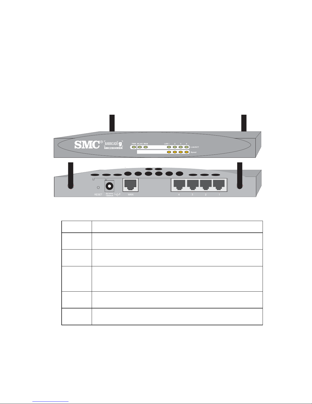
The following figure shows the components of the Wireless
Barricade™:
Figure 1. Front and Rear Panels
Item Description
LEDs Power, WLAN, WAN and LAN port status indicators.
(See "LED Indicators" on page 2.)
Reset
Button
Power
Inlet
WAN
Port
LAN
Ports
Use this button to reset the power and restore the default factory
settings.
Connect the included power adapter to this inlet.
Warning: Using the wrong type of power adapter may damage
your router.
WAN port (RJ-45). Connect your cable modem, DSL modem,
or an Ethernet router to this port.
Fast Ethernet ports (RJ-45). Connect devices (such as a PC,
hub or switch) on your local area network to these ports.
7
Page 11

Installing the Wireless Barricade™ g Router
System Requirements
You must have an ISP that meets the following minimum
requirements:
• Internet access from your local telephone company or Internet
Service Provider (ISP) using a DSL modem or cable modem.
•
A PC using a fixed IP address or dynamic IP address assigned
via DHCP, as well as a Gateway server address and DNS
server address from your service provider.
• A computer equipped with a 10 Mbps, 100 Mbps, or
10/100 Mbps Fast Ethernet card, or a USB-to-Ethernet
converter.
• TCP/IP network protocol installed on each PC that needs
to access the Internet.
• A web browser, such as Microsoft Internet Explorer 5.0 or
above installed on one PC at your site for configuring the
Wireless Barricade™.
Connect the System
The Wireless Barricade™ can be positioned at any convenient
location in your office or home. No special wiring or cooling
requirements are needed. You should, however comply
with the following guidelines:
• Keep the Wireless Barricade™ away from any heating
devices.
• Do not place the Wireless Barricade™ in a dusty or wet
environment.
You should also remember to turn off the power, remove the
power cord from the outlet, and keep your hands dry when
you install the Wireless Barricade™.
8
Page 12
Basic Installation Procedure
1. Connect the LAN: Connect the Wireless Barricade™ to your
PC, or to a hub or switch. Run Ethernet cable from one of
the LAN ports on the rear of the Wireless Barricade™ to your
computer’s network adapter or to another network device.
You may also connect the Wireless Barricade™ to your PC
(using a wireless client adapter) via radio signals. Position
both antennas on the back of the Wireless Barricade™ into
the desired positions. For more effective coverage, position
Connect the System
the antennas along different axex. For example, try positioning
the antennas around 45 to 90 degress apart.
(The antennas emit signals along the toroidal plane –
and thus provide more effective coverage when
positioned along different axes).
2. Connect the W AN: Prepare an Ethernet cable f or connecting
Wireless Barricade™ to a cable/xDSL modem or Ethernet
the
router.
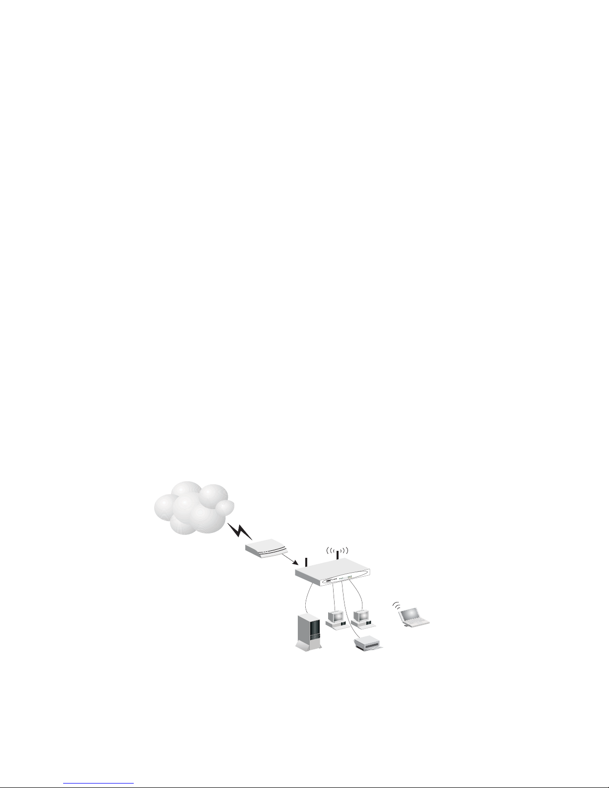
3. Power on: Connect the power adapter to the Wireless
Barricade™.
Internet
Internet
Access
Device
Wireless
Broadband
Cable/DSL
Router
Figure 2. Connecting the Wireless Barricade™ g Router
SOHO Office
or Residence
3
2
k
n
i
L
1
N
A
L
y
t
i
v
i
t
c
A
N
A
W
N
A
L
W
R
W
P
MC7004AWBR
S
Notebook with
Wireless PC Card
9
Page 13
Installing the Wireless Barricade™ g Router
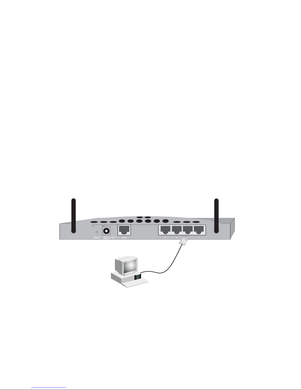
Attach to Your Network Using Ethernet Cabling
The four LAN ports on the Wireless Barricade™ auto-negotiate
the connection speed to 10 Mbps Ethernet or 100 Mbps Fast
Ethernet, and the transmission mode to half duplex or full duplex.
Use twisted-pair cable to connect any of the four LAN ports
on the Wireless Barricade™ to an Ethernet adapter on your
PC. Otherwise, you can cascade any of the LAN ports on the
Wireless Barricade™ to an Ethernet hub or switch, and then
connect your PC or other network equipment to the hub or
switch. When inserting an RJ-45 plug, be sure the tab on
the plug clicks into position to ensure that it is properly seated.
Warning: Do not plug a phone jack connector into any RJ-45
port. This may damage the Wireless Barricade™.
Instead, use only twisted-pair cables with RJ-45
connectors that conform with FCC standards.
Figure 3. Making the LAN Connections
10
Page 14

Connect the System
Attach to Your Network Using Radio Signals
Install a wireless network adapter in each computer that will be
connected to the Internet or your local network via radio signals.
SMC currently offers several wireless network cards, including
the
SMC2802W and SMC2835W wireless cards.
Rotate both antennas on the back of the Wireless Barricade™
to the desired position. For more effective coverage, position
the antennas around 45 to 90 degrees apart. Try to place the
Wireless Barricade™ in a position that is located in the center
of
your wireless network. Normally, the higher you place the
antenna,
Barricade™’s location provides optimal reception throughout
your home or office.
Computers equipped with a wireless adapter can communicate
with each other as an independent wireless LAN by configuring
each computer to the same radio channel. However, the Wireless
Barricade™ can provide access to your wired/wireless LAN or
to the Internet for all wireless workstations. Each wireless PC
in this network infrastructure can talk to any computer in the
wireless group via a radio link, or access other computers or
network resources in the wired LAN infrastructure or over
the Internet via the Wireless Barricade™.
the better the performance. Ensure that the Wireless
The wireless infrastructure configuration not only extends the
accessibility of wireless PCs to the wired LAN, but also increases
the effective wireless transmission range for wireless PCs by
retransmitting incoming radio signals through the Wireless
Barricade™.
11
Page 15
Installing the Wireless Barricade™ g Router
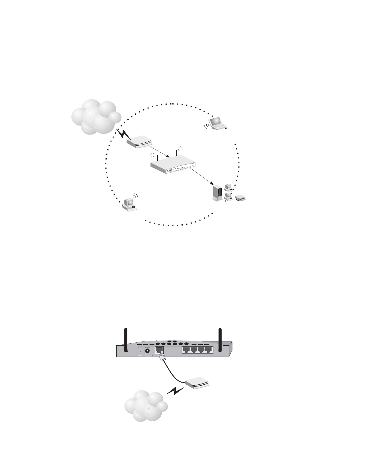
A wireless infrastructure can be used for access to a central
database, or for connection between mobile workers, as
shown in the following figure:
Wired to Wireless
Network Extension
Internet
Internet
Access
Device
Wireless
Broadband
N
A
W
N
A
L
W
R
W
P
R
MC7004AWB
S
Cable/DSL
Router
Notebook with Wireless
PC Card Adapter
23
k
n
i
L
1
N
A
L
t
y
i
v
i
t
c
A
Wired LAN
PCwith Wireless
PCI Adapter
Figure 4. Making the WLAN Connections
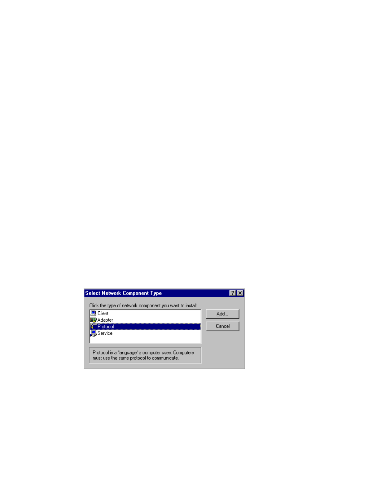
Attach the Wireless Barricade™ g Router to the Internet
If Internet services are provided through an xDSL or cable
modem, use unshielded or shielded twisted-pair Ethernet
cable (Category 3 or greater) with RJ-45 plugs to connect the
broadband modem directly to the WAN port on the Wireless
Barricade™.
Figure 5. Making the WAN Connection
12
DSL/Cable
Modem
ISP
(Primary)
Page 16

Connect the System
Note: When connecting to the WAN port, use 100-ohm
Category 3, 4, or 5 shielded or unshielded twistedpair cable with RJ-45 connectors at both ends for
all connections.
Connecting the Power Adapter
Plug the power adapter into the power socket on the Wireless
Barricade™, and the other end into a power outlet. Check the
indicator marked "PWR" on the front panel to be sure it is on.
If the power i
on page 79
ndicator does not light, refer to
.
"Troubleshooting"
13
Page 17
If you have not previously installed the TCP/IP protocols on your
client PCs, refer to the following section. If you need information
on how to configure a TCP/IP address on a PC, refer to "Setting
Up TCP/IP" on page 18.
Installing TCP/IP
Windows 95/98/Me
1. Click Start/Settings/Control Panel.
2. Double-click the Network icon and select the Configuration
tab in the Network window.
CONFIGURING
CLIENT TCP/IP
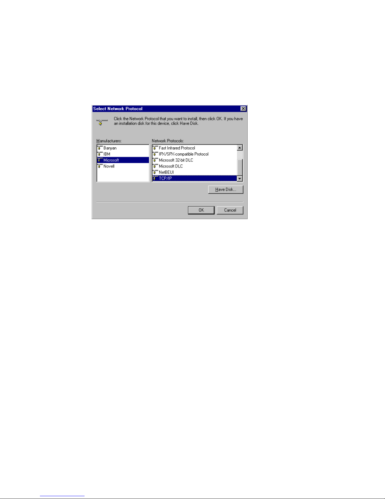
3. Click the Add button.
4. Double-click Protocol.
15
Page 18
Configuring Client TCP/IP
5. Select Microsoft in the manufacturers list. Select TCP/IP
in the Network Protocols list. Click the OK button to return
to the Network window.
6. The TCP/IP protocol will be listed in the Network window.
Click OK. The operating system may prompt you to restart
your system. Click Yes and the computer will shut down
and restart.
Windows 2000
1. Click the Start button and choose Settings, then click the
Network and Dial-up Connections icon.
2. Double-click the Local Area Connection icon, and click the
Properties button on the General tab.
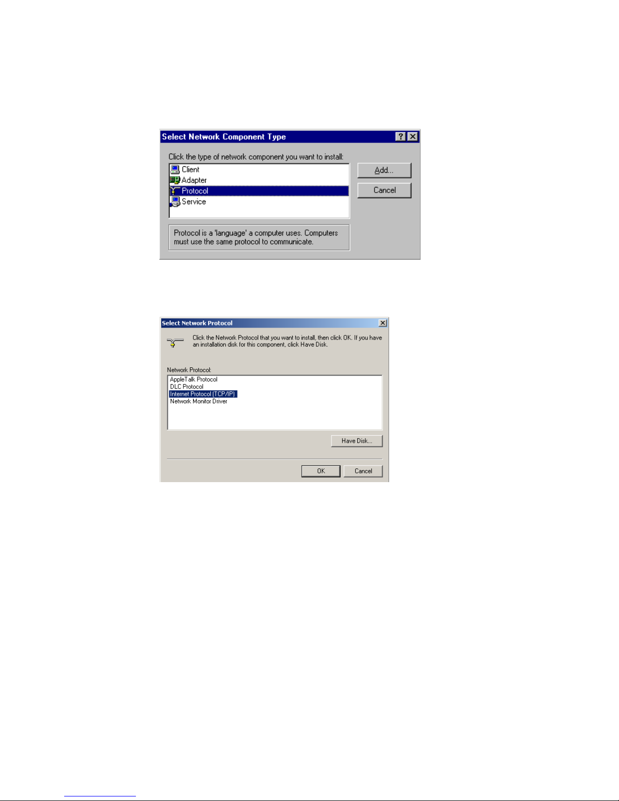
3. Click the install... button.
16
Page 19
Installing TCP/IP
4. Double-click Protocol.
5. Choose Internet Protocol (TCP/IP). Click the OK button
to return to the Network window.
6. The TCP/IP protocol will be listed in the Network window.
Click OK to complete the installation procedure.
17
Page 20

Configuring Client TCP/IP
Setting Up TCP/IP
To access the Internet through the Wireless Barricade™, you
must configure the network settings of the computers on your
LAN to use the same IP subnet as the Wireless Barricade™.
The default network settings for the Wireless Barricade™ are:
Gateway IP Address: 192.168.2.1
Subnet Mask: 255.255.255.0
Note: These settings may be changed to suit your network
requirements, but you must first configure at least
one computer as described in this chapter to access
the Wireless Barricade™’s web configuration interface.
See "Configuring the Wireless Barricade™ g Router"
on page 29 for information on configuring the Wireless
Barricade™.
If you have not previously configured TCP/IP for your computer,
refer to"Configuring Client TCP/IP" on page 15. The IP address
of the connected client PC should be 192.168.2.x (where x
means 2–254). You can set the IP address for client PCs either
by automatically obtaining an IP address from the Wireless
Barricade™’s DHCP service or by manual configuration.
Configuring Your Computer in Windows 95/98/Me
You may find that the instructions here do not exactly match your
version of Windows. This is because these steps and screenshots
were created in Windows 98. Windows 95 and Windows Millennium
Edition are very similar, but not identical, to Windows 98.
1. From the Windows desktop, click Start/Settings/
Control Panel.
2. In the Control Panel, locate and double-click the
Network icon.
18
Page 21
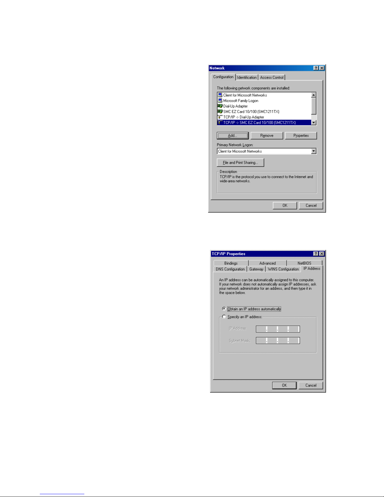
3. On the Network window
Configuration tab,
double-click the TCP/IP
entry for your network
card.
Setting Up TCP/IP
4. Click the IP Address tab.
5. Click the "Obtain an
IP address" option.
6. Next click on the Gateway
tab and verify the Gatewa y
field is blank. If there are
IP addresses listed in the Gateway section, highlight
each one and click Remove until the section is empty.
7. Click the OK button to close the TCP/IP Properties window.
19
Page 22
Configuring Client TCP/IP
8. On the Network Properties Window, click the OK button
to save these new settings.
Note: Windows may ask you for the original Windows
installation disk or additional files. Check for
the files at c:\windows\options\cabs, or insert
your Windows CD-ROM into your CDROM drive
and check the correct file location, e.g., D:\win98,
D:\win9x. (if D is the letter of your CD-ROM drive).
9. Windows may prompt you to restart the PC. If so, click
the Yes button. If Windows does not prompt you to restart
your computer, do so to insure your settings.
Obtain IP Settings from Your Wireless Barricade™ g Router
Now that you have configured your computer to connect to your
Wireless Barricade™, it needs to obtain new network settings.
By releasing old IP settings and renewing them with settings
from your Wireless Barricade™, you will also verify that you
have configured your computer correctly.
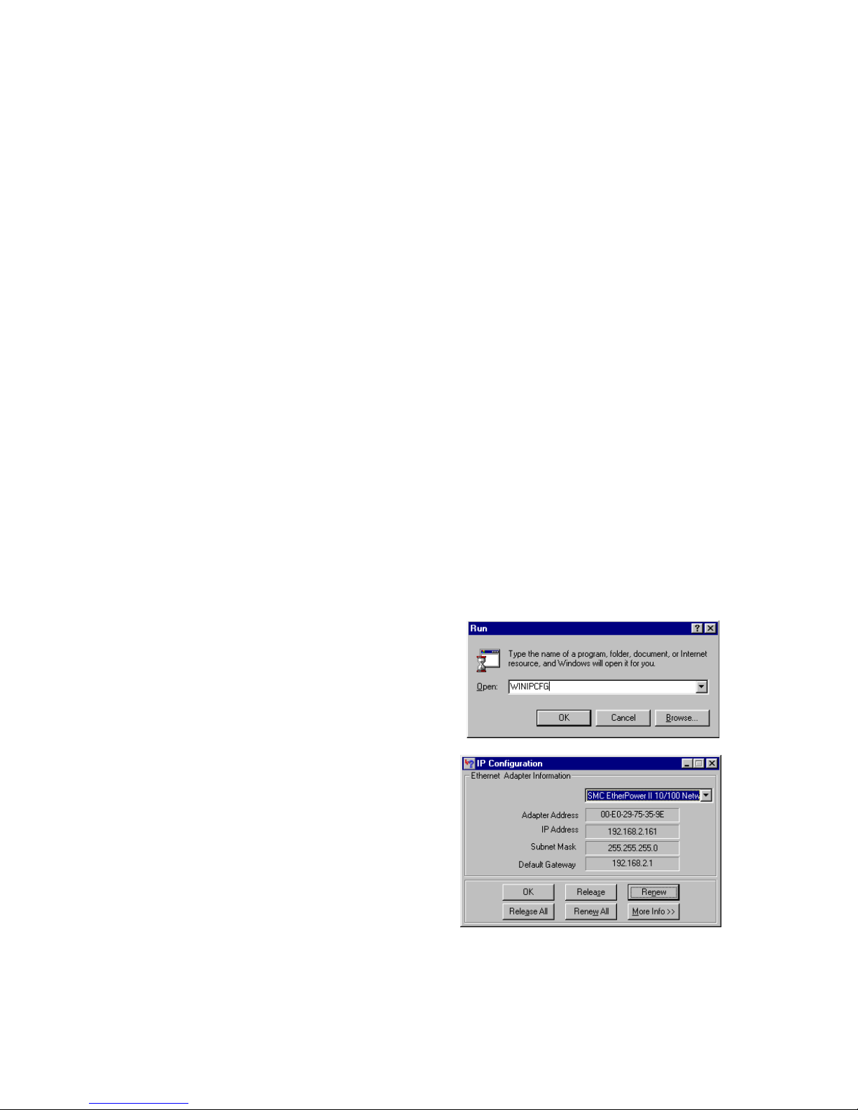
1. Click Start/Run.
2. Type WINIPCFG and
click OK.
3. From the drop-down menu,
select your network card.
Click Release and then
Renew. Verify that your
IP address is now
192.168.2.xxx, your Subnet
Mask is 255.255.255.0 and
your Default Gateway is
192.168. 2.1. These values
confirm that the Wireless Barricade™ is functioning.
Click OK to close the IP Configuration window.
20
Page 23
Setting Up TCP/IP
Configuring Your Computer in Windows NT 4.0
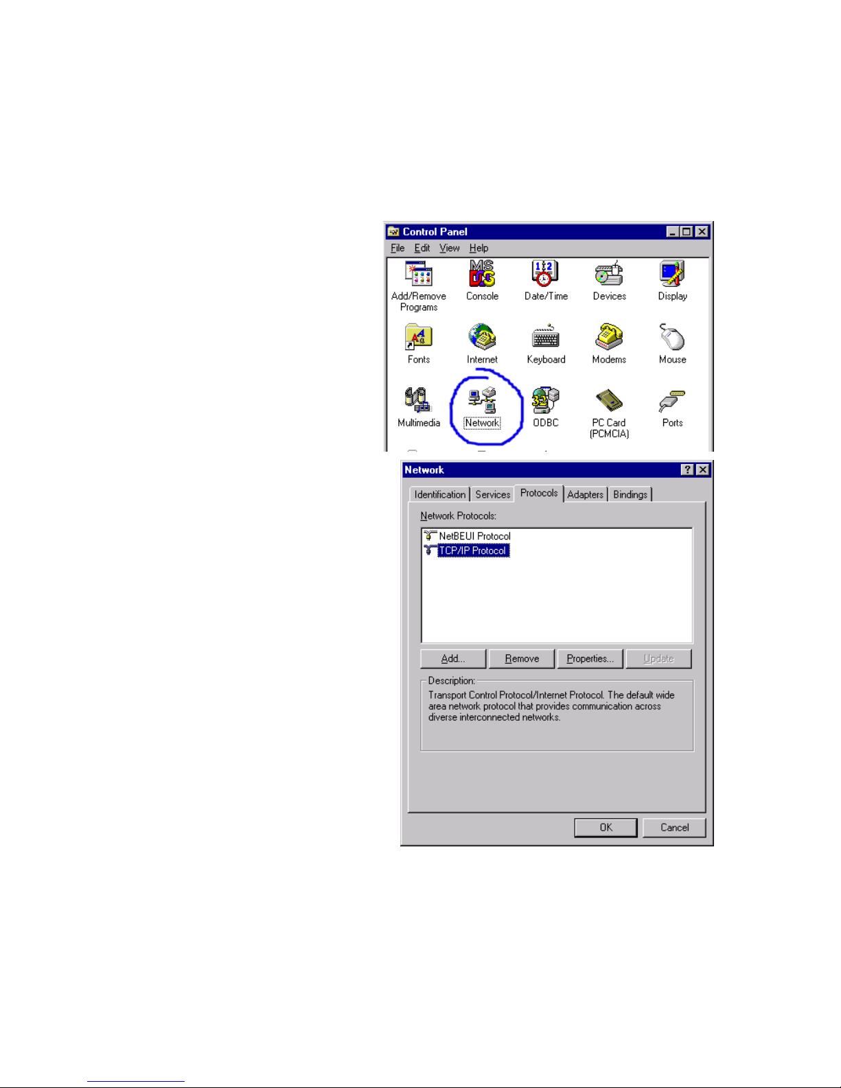
1. From the Windows desktop click Start/Settings/Control Panel.
2. Double-click the
Network icon.
3. Click on the
Protocols tab.
4. Double-click
TCP/IP Protocol.
5. Click on the IP
Address tab.
6. In the Adapter drop-down list, be sure your Ethernet adapter
is selected.
21
Page 24
Configuring Client TCP/IP
7. Click on "Obtain an IP address from a DHCP server."
8. Click OK to close the window.
9. Windows may copy files and will then prompt you to restart
your system. Click Yes and your computer will shut down
and restart.
Obtain IP Settings From Your Wireless Barricade™ g Router
Now that you have configured your computer to connect to the
Wireless Barricade™, it needs to obtain new network settings.
By releasing old IP settings and renewing them with settings
from the Wireless Barricade™, you will also verify that you
have configured your computer correctly.
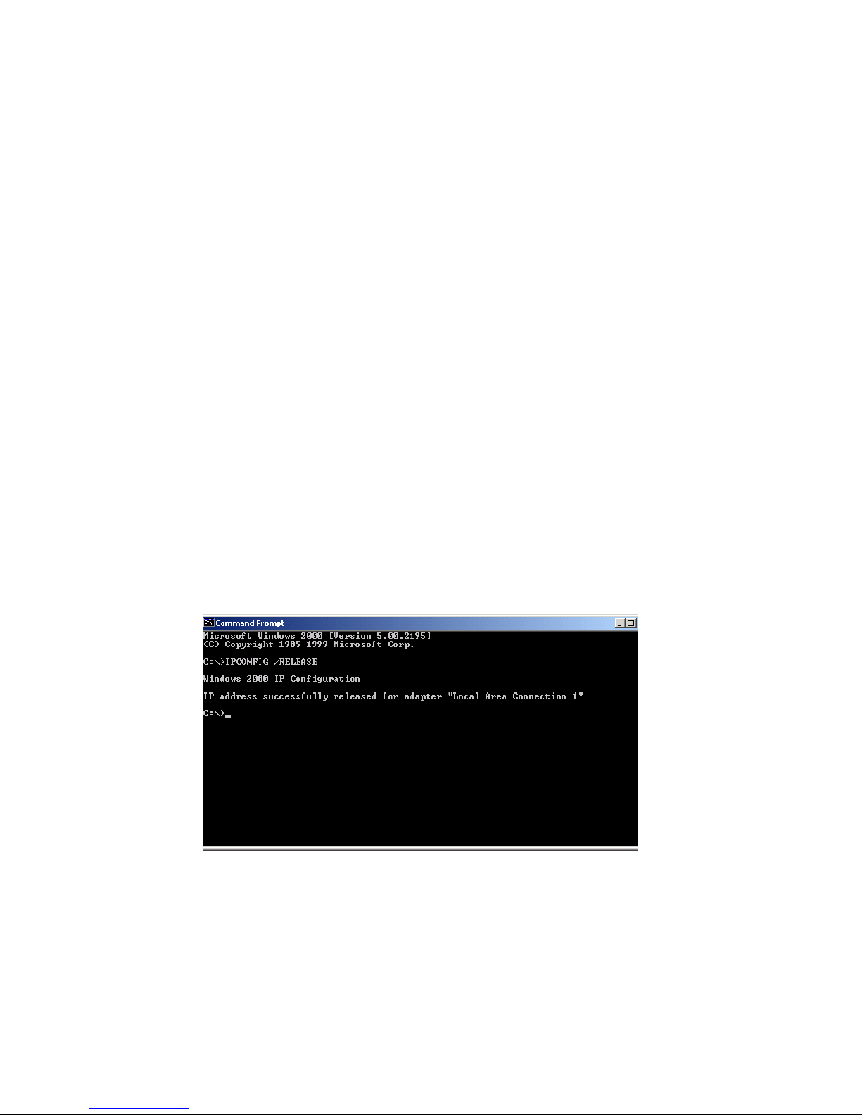
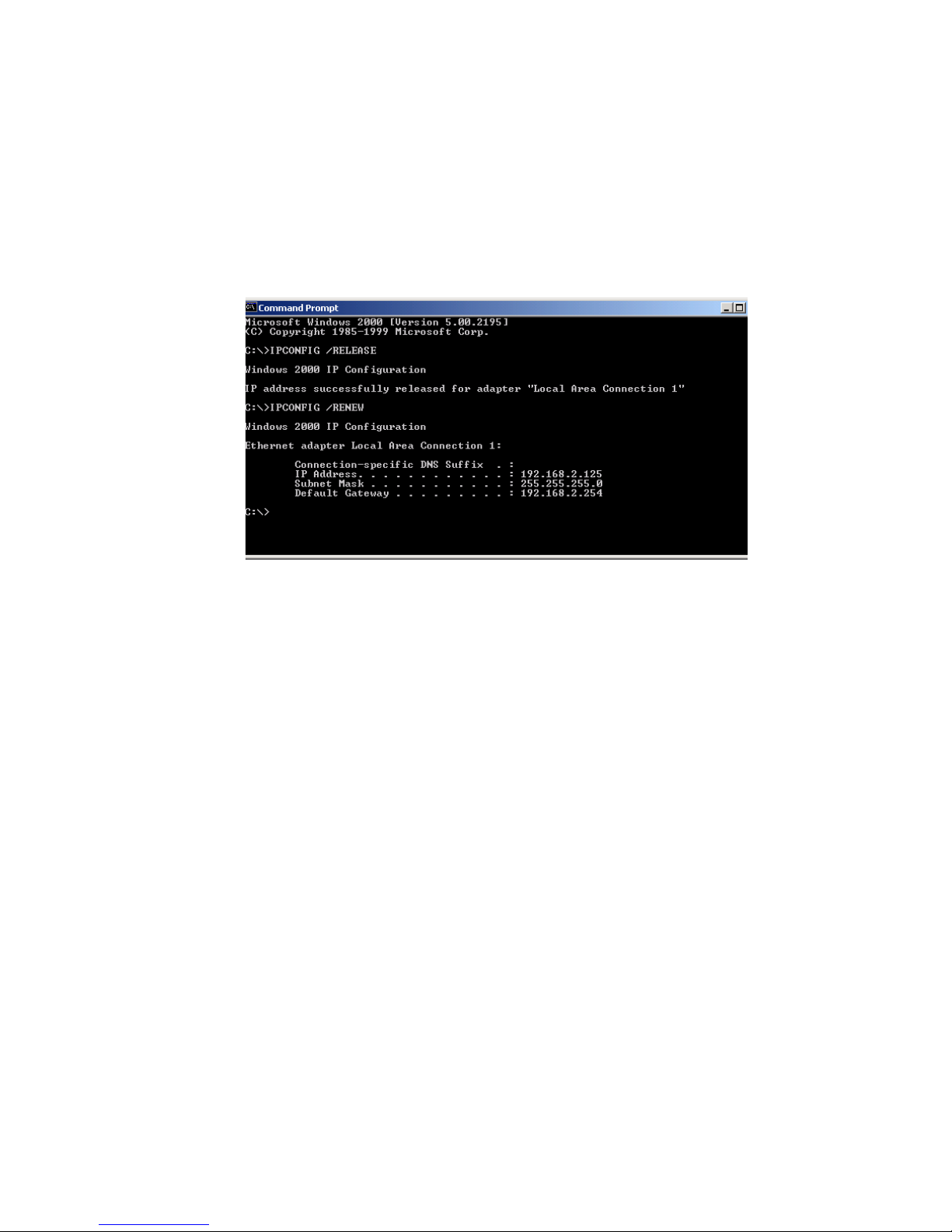
1. On the Windows desktop, click Start/Programs/Command
Prompt.
2. In the Command Prompt window , type IPCONFIG /RELEASE
and press the <ENTER> key.
22
Page 25
Setting Up TCP/IP
3. Type IPCONFIG /RENEW and press the <ENTER> key. Verify
that your IP Address is now 192.168.2.xxx, y our Subnet Mask
is 255.255.255.0 and your Default Gateway is 192.168.2.1.
These values confirm that the Wireless Barricade™ is
functioning.
4. Type EXIT and press <ENTER> to close the Command
Prompt window.
Configuring Your Computer in Windows 2000
1. Access your Network settings by clicking Start, then choose
Settings and then select Control Panel.
2. In the Control Panel, locate and double-click the Network
and Dial-up Connections icon.
23
Page 26

Configuring Client TCP/IP
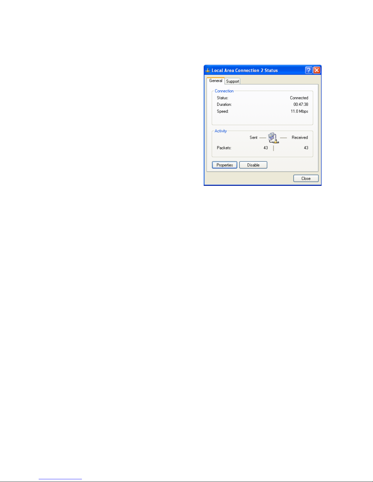
3. Locate and double-click the
Local Area Connection icon
for the Ethernet adapter that
is connected to the Wireless
Barricade™. When the Status
dialog box window opens,
click the Properties button.
4. In the Local Area Connection
Properties box, verify the box
next to Internet Protocol
(TCP/IP) is checked. Then
highlight the Internet Protocol (TCP/IP), and click the
Properties button.
5. Select "Obtain an IP address automatically" to configure your
computer for DHCP. Click the OK button to save this change
and close the Properties window.
6. Click the OK button again to save these new changes.
7. Reboot your PC.
8. To obtain new network settings see "Obtain IP Settings
from Your Wireless Barricade™ g Router" on page 20.
Configuring Your Computer in Windows XP
The following instructions assume you are running Windows XP
with the default interface. If you are using the Classic interface
(where the icons and menus look like previous Windows versions)
please follow the instructions for Windows 2000 outlined above.
1. Access your Network settings by clicking Start, choose
Control Panel, select Network and Internet Connections
and then click on the Network Connections icon.
,
24
Page 27
Setting Up TCP/IP
2. Locate and double-click the
Local Area Connection icon
for the Ethernet adapter that
is connected to the Wireless
Barricade™. Next, click the
Properties button.
3. In the Local Area Connection Properties box, verify the box
next to Internet Protocol (TCP/IP) is checked. Then highlight
the Internet Protocol (TCP/IP), and click the Properties button
.
4. Select "Obtain an IP address automatically" to configure your
computer for DHCP. Click the OK button to save this change
and close the Properties window.
5. Click the OK button again to save these new changes.
6. Reboot your PC.
Configuring a Macintosh Computer
You may find that the instructions here do not exactly match
your screen. This is because these steps and screenshots were
created using Mac OS 10.2. Mac OS 7.x and above are all very
similar, but may not be identical to Mac OS 10.2.
1. Pull down the Apple Menu. Click System Preferences
and select Network.
25
Page 28
Configuring Client TCP/IP
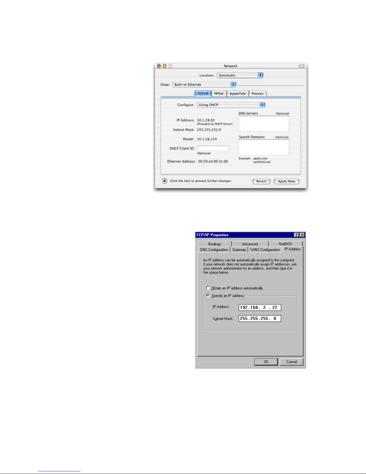
2. Make sure that
Built-in Ethernet
is selected in the
Show field.
3. On the TCP/IP
tab, select Using
DHCP in the
Configure field.
4. Close
the TCP/IP
dialog box.
Manual IP Configuration (for all Windows OS)
1. Check Specify an IP
address on the IP Address
tab. Enter an IP address
based on the default
network 192.168.2.x (where
x is
between 2 and 254), and
use 255.255.255.0 for the
subnet mask.
26
Page 29
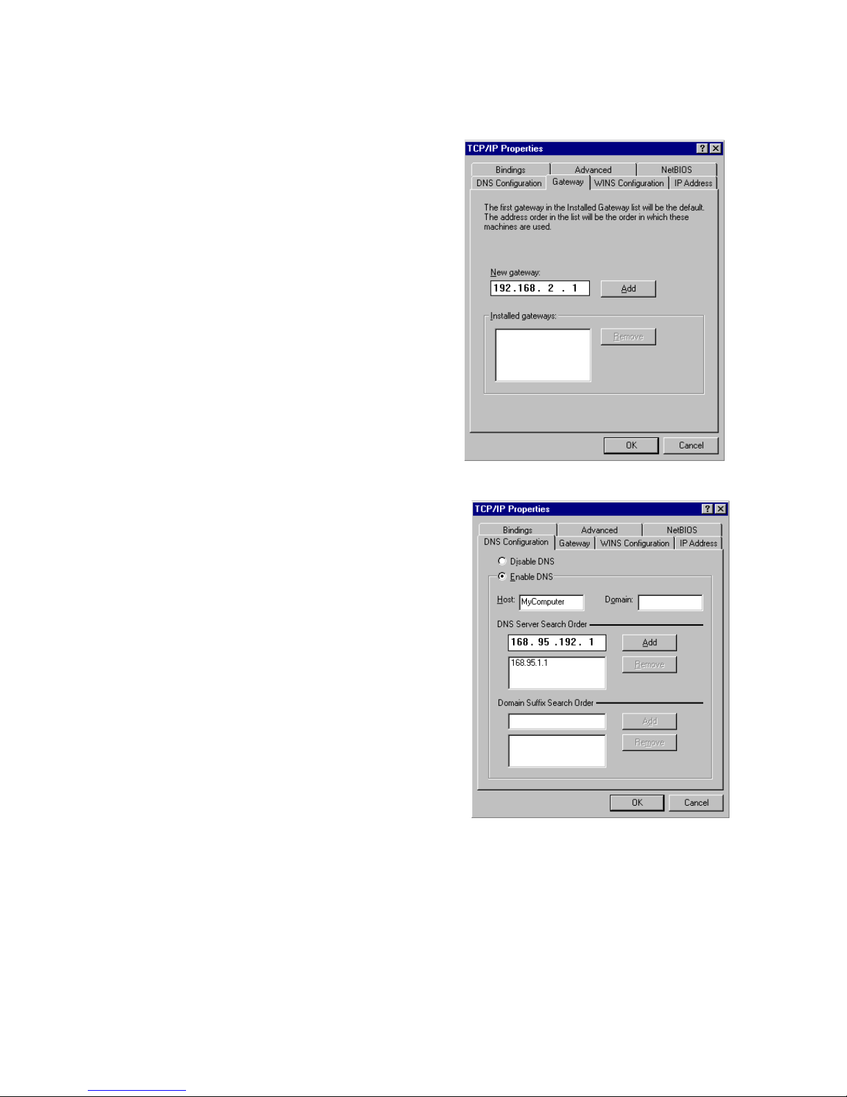
2. In the Gateway tab, add the
IP address of the Wireless
Barricade™
(default: 192.168.2.1) in
the New gateway field and
click Add.
Setting Up TCP/IP
3. On the DNS Configuration
tab, add the IP address for
the Wireless Barricade™
and click Add. This
automatically relays
DNS requests to the DNS
server(s) provided by your
ISP. Otherwise, add specific
DNS servers into the DNS
Server Search Order field
and click Add
4. After finishing TCP/IP setup,
click OK, and then reboot
the computer. After that, set
up other PCs on the LAN
according to the procedures
described above.
.
27
Page 30

Configuring Client TCP/IP
Verifying Your TCP/IP Connection
After installing the TCP/IP communication protocols and configuring
an IP address in the same network as the Wireless Barricade™,
use the Ping command to check if your computer has successfully
connected to the Wireless Barricade™. The following example
shows how the Ping procedure can be executed in an MS-DOS
window. First, execute the Ping command:
ping 192.168.2.1
If a message similar to the following appears:
Pinging 192.168.2.1 with 32 bytes of data:
Reply from 192.168.2.1: bytes=32 time=2ms TTL=64
a communication link between your computer and the Wireless
Barricade™ has been successfully established.
If you get the following message,
Pinging 192.168.2.1 with 32 bytes of data:
Request timed out.
there may be something wrong in your installation procedure.
Check the following items in sequence:
1. Is the Ethernet cable correctly connected between
the Wireless Barricade™ and the computer?
The LAN LED on the Wireless Barricade™ and
the Link LED of the network card on your computer
must be on.
2. Is TCP/IP properly configured on your computer?
If the IP address of the Wireless Barricade™ is 192.168.2.1,
the IP address of your PC must be from 192.168.2.2 -
192.168.2.254 and the default gateway must be 192.168.2.1.
If you can successfully Ping the Wireless Barricade™
you are now ready to connect to the Internet!
28
Page 31

C
ONFIGURING THE
B
ARRICADE
The Wireless Barricade™ g Router can be configured by Internet
Explorer 5.0 or above. Using the web management interface,
you can configure the Wireless Barricade™ and view statistics
to monitor network activity.
Note: Before you attempt to configure your router, if you have
access to the Internet please visit www.smc.com
www.smc-europe.com and download the latest firmware
update to ensure your Wireless Barricade™ is running
the latest firmware.
Before you attempt to log into the web-based Administration,
please verify the following.
™
W
G
R
IRELESS
OUTER
or
1. Your browser is configured properly (see below).
2. Disable any firewall or security software that may be running.
3. Confirm that you have a good link LED where your computer
is plugged into the Wireless Barricade™. If you don’t have
a link light, then try another cable until you get a good link.
Browser Configuration
Confirm your browser is configured for a direct connection to the
Internet using the Ethernet cable that is installed in the computer.
This is configured through the options/preference section of your
browser.
29
Page 32

Configuring the Wireless Barricade™ g Router
Disable Proxy Connection
You will also need to verify that the HTTP Proxy feature of your
web browser is disabled. This is so that your web browser will
be able to view the Wireless Barricade™ configuration pages.
The following steps are for Internet Explorer.
Internet Explorer 5 or above (For Windows)
1. Open Internet Explorer. Click Tools, and then select Internet
Options.
2. In the Internet Options window, click the Connections tab.
3. Click the LAN Settings button.
4. Clear all the check boxes and click OK to save these LAN
settings changes.
5. Click OK again to close the Internet Options window.
Internet Explorer (For Macintosh)
1. Open Internet Explorer. Click Explorer/Preferences.
2. In the Internet Explorer Preferences window, under Network,
select Proxies.
3. Uncheck all check boxes and click OK.
30
Page 33

Navigating the Web Browser Interface
Navigating the Web Browser Interface
To access the
Wireless Barricade™’s
management interface,
enter the Wireless
Barricade™ IP address in
your web browser http://
192.168.2.1 Then enter
the password and click
LOGIN. (Default: smcadmin.)
Note: Passwords can contain from 3–12 alphanumeric
characters and are case sensitive.
The home page displays the Setup Wizard and Advanced
Setup options.
31
Page 34

Configuring the Wireless Barricade™ g Router
The Wireless Barricade™’s management interface features a
Setup Wizard and an Advanced Setup section. Use the Setup
Wizard if you want to quickly set up the Wireless Barricade™
for use with a cable modem or DSL modem.
Advanced setup supports more advanced functions like hacker
attack detection, IP and MAC address filtering, intrusion detection,
virtual server setup, virtual DMZ hosts, and other advanced
functions.
Making Configuration Changes
Configurable parameters have a dialog box or a drop-down list.
Once a configuration change has been made on a page, be
sure to click the APPLY or NEXT button at the bottom of the
page to enable the new setting.
Note: To ensure proper screen refresh after a command
entry, ensure that Internet Explorer 5.0 is configured
as follows: Under the menu Tools/Internet Options/
General/Temporary Internet Files/Settings, the setting
for "Check for newer versions of stored pages" should
be "Every visit to the page".
32
Page 35

Setup Wizard
Time Zone
Click on the Setup Wizard picture. The first item in the Setup
Wizard is Time Zone setup.
Setup Wizard
For accurate timing of client filtering and log events, you need to
set the time zone. Select your time zone from the drop-down list,
and click NEXT.
33
Page 36

Configuring the Wireless Barricade™ g Router
Broadband Type
Select the type of broadband connection you have.
For a cable modem connection see the following page. For a
Fixed-IP xDSL connection see "Fixed-IP xDSL" on page 35,
for a PPPoE xDSL connection, see "PPPoE xDSL" on page 36,
for a PPTP connection, see "Point-to-Point Tunneling Protocol
(PPTP)" on page 37, and for BigPond connection, see
"BigPond" on page 38.
34
Page 37

Setup Wizard
Cable Modem
Your Internet Service Provider may have given you a host name.
If so, enter it into the field.
Click Finish to complete the setup. The Status page will
open to allow you to view the connection status, as well
as other information. See "Status" on page 78 for details.
Fixed-IP xDSL
Some xDSL Internet Service Providers may assign a fixed
(static) IP address. If you have been provided with this
information, choose this option and enter the assigned
IP address, gateway IP address, DNS IP addresses,
and subnet mask. Click FINISH to complete the setup.
35
Page 38

Configuring the Wireless Barricade™ g Router
PPPoE xDSL
Enter the PPPoE User Name and Password assigned by your
Service Provider. The Service Name is normally optional, but
may be required by some service providers.
Leave the Maximum Transmission Unit (MTU) at the default
value (1454) unless you have a particular reason to change it.
Enter a Maximum Idle Time (in minutes) to define a maximum
period of time for which the Internet connection is maintained
during inactivity. If the connection is inactive for longer than
the Maximum Idle Time, it will be dropped. (Default: 10).
Enable the Auto-reconnect option to automatically re-establish
the connection as soon as you attempt to access the Internet
again. Click FINISH to complete the setup.
Note: Please be aware that the setting of [Maximum Idle
Time] to "0" and/or [Auto-Reconnect] enabled can
cause an increase of your telephone bill if you don't
have signed a flatrate.
36
Page 39

Setup Wizard
Point-to-Point Tunneling Protocol (PPTP)
Point-to-Point Tunneling Protocol is a common connection
method used for xDSL connections in Europe. It can be
used to join different physical networks using the Internet
as an intermediary.
If you have been provided with the information as shown on the
screen, enter the PPTP Account name and password, Host Name,
Service IP Address, the assigned IP address, and subnet mask.
Leave the Maximum Transmission Unit (MTU) at the default
value (1460) unless you have a particular reason to change it.
Enter a Maximum Idle Time (in minutes) to define a maximum
period of time for which the Internet connection is maintained
during inactivity. If the connection is inactive for longer than
the Maximum Idle Time, it will be dropped. (Default: 10).
Enable the Auto-reconnect option to automatically re-establish
the connection as soon as you attempt to access the Internet
again. Click FINISH to complete the setup.
Note: Please be aware that the setting of [Maximum Idle
Time] to "0" and/or [Auto-Reconnect] enabled can
cause an increase of your telephone bill if you don't
have signed a flatrate.
37
Page 40

Configuring the Wireless Barricade™ g Router
BigPond
If you use the BigPond Internet Service which is available
in Australia, enter the the user name, password and service
name for BigPond authentication. Click FINISH to complete
the setup.
Advanced Setup
Use the web management interface to define system parameters,
manage and control the Wireless Barricade™ and its ports, or
monitor network conditions. The following table outlines the
selections available from this program.
Menu Description
System • Sets the local time zone, the password for administrator
access, the Internet security of ZoneAlarm Pro (optional),
system log server, and the IP address of a PC that will
be allowed to manage the Wireless Barricade™ remotely.
• Sets enhanced security policy for the network using Zone
Labs, Inc "ZoneAlarm Pro."
WAN • Specifies the Internet connection type: (1) Dynamic IP host
configuration and the physical MAC address of each media
interface, (2) PPPoE configuration, (3) PPTP, (4) Static IP
and ISP gateway address, or (5) BigPond (Internet service
available in Australia).
• Specifies DNS servers to use for domain name resolution.
LAN Sets the TCP/IP configuration of the Wireless Barricade™’s LAN
interface and all DHCP clients.
NAT Shares a single ISP account with multiple users, sets up virtual
38
servers.
Page 41

Advanced Setup
Menu Description
Wireless Configures the radio frequency, SSID, WPA/WEP encryption,
and 802.1x for wireless communications.
Firewall Configures a variety of security and specialized functions,
including: Access Control, Hacker Prevention, and DMZ.
DDNS Dynamic DNS provides users on the Internet with a method
to tie their domain name to a computer or server.
UPnP With Universal Plug and Play, a device can automatically and
dynamically join a network, obtain an IP address, communicate
its capabilities, and learn about the presence and capabilities of
other devices. Devices can then directly communicate with each
other. This further enables peer-to-peer networking.
Tools Contains options to back up & restore the current configuration,
restore all configuration settings to the factory defaults, update
system firmware, or reset the system.
Status Provides WAN connection type and status, firmware and
hardware version numbers, system IP settings, as well as
DHCP, NAT, and Firewall information.
Displays the number of attached clients, the firmware versions,
the physical MAC address for each media interface, and the
hardware version and serial number.
Shows the security and DHCP client log.
39
Page 42

Configuring the Wireless Barricade™ g Router
System
Time Zone
40
Set the time zone and time server for the Wireless Barricade™.
This information is used for log entries and client access control.
• Set your local time zone settings
Select your time zone from the drop-down list, and set the
start and end dates if your area requires daylight savings.
To automatically update the Wireless Barricade™’s internal
clock by synchronizing with a public time server over the Internet,
choose one of the methods below.
• Get date and time by online time servers (Network Time
Protocol)
Choose the online standard time server of your area from the
drop-down menu, or enter the IP address of the time server
on your network.
Page 43

Advanced Setup
• Set date and time using PC's date and time
Click on the radio button for synchronizing the Wireless
Barricade™’s internal clock with the host PC.
• Set date and time manually
For manually setting the date and time, configure the date by
selecting the options from the drop-down list, and enter the
digits for the time.
Password Settings
Use this menu to restrict access based on a password. For
security you should assign your own password before exposing
the Wireless Barricade™ to the Internet. (Default: smcadmin.)
Passwords can contain from 3 –12 alphanumeric characters
and are case sensitive.
Note: If your password is lost, or you cannot gain access
to the user interface, press the Reset button on the
rear panel (holding it down for at least five seconds)
to restore the factory defaults.
41
Page 44

Configuring the Wireless Barricade™ g Router
Enter a maximum Idle Time Out (in minutes) to define a maximum
period of time for which the login session is maintained during
inactivity. If the connection is inactive for longer than the maximum
idle time, it will perform system logout, and you have to log into
the web management system again. (Default: 9 minutes.)
Remote Management
Remote Management allows a remote PC to configure, manage,
and monitor the Wireless Barricade™ using a standard web
browser.
remote host. Click APPLY. (Default: Disable.)
Note: If you select Any IP Address in the Allow Access to
Check Enable and set the IP address (range) of the
field, any host can manage the Wireless Barricade™.
42
Page 45

Advanced Setup
ZoneAlarm Pro® with Web Filtering Setup
Every PC connected to the Internet is a potential target. Even
a novice hacker can easily initiate tens of thousands of pings
and port scans per hour, scanning far and wide for unprotected
systems. Once hackers find your PC, they attempt to compromise
it and deposit malicious software such as remote-access Trojans,
spy-ware, viruses, or Internet worms.
Your Wireless Barricade™ now includes a new "Client Enforcement"
feature from Zone Labs, Inc. Client Enforcement provides end
to end security by ensuring that only protected endpoint PC’s have
access to the network. Simply configure your Wireless Barricade™
to restrict the network access of endpoint PCs that are not in
compliance with security requirements. This easy-to-use feature
allows you to ensure each of your PCs is safe from Trojan horse
and Spy-ware style attacks.
ZoneAlarm
®
Pro protects your PC from both known and unknown
threats with a combination of:
• Stealth firewall that protects each individual computer
in your network, and it travels with that computer wherever
it goes. Mobile endpoint protection is a must for traveling
laptops.
•
Program Control
to the Internet, blocking spy-ware and other malicious software
to manage which applications are connecting
from sending your personal information out from your computer.
• MailSafe to identify and quarantine potentially harmful email
attachments (coming in and going out) to prevent e-mail viruses,
worms and Trojans disguised as attachments from getting
onto to your machine and mass-e-mail worms from sending
viruses out to the people in your address book. And
43
Page 46

Configuring the Wireless Barricade™ g Router
• Privacy protection to keep your identity and web-surfing
habits confidential with features such as cookie control,
3rd-party spy protection and cache cleaner to protect
your privacy while you surf and ad-blocking and parental
control keep your surfing safe and distraction-free.
By refusing Internet or WAN access to any workstation not
running ZoneAlarm Pro security of your network is greatly
increased. You can easily make exceptions for individual
workstations at your discretion. When an Internet request
is rejected, the user will be routed to http://smc.zonelabs.com
where (s)he will be given the option to purchase ZoneAlarm
Pro or upgrade to the proper version required by the policy.
The option does not significantly affect system performance,
so we advise enabling it to protect your network users.
Select Enable and click the APPLY button.
Note: When you select the Enable radio button of the Enable
®
or Disable ZoneAlarm
Pro Security field, be sure to
press the APPLY button.
44
Page 47

Advanced Setup
• License Key
The License Key field is optional. To input your ZAP License
Number, type in or paste the license number you received
at the time of purchase.
Note: Only Licenses for ZoneAlarm Pro with Web Filtering 4.x
and higher,
can be inserted directly into this field.
Click the Buy ZoneAlarm Pro Now! to purchase a license.
You will be directed to http://smc.zonelabs.com
where you can complete your product purchase.
• Version Requirement for Internet Access
The Version Requirement for Internet Access field is an optional
setting. This field gives you even tighter control of the enforcement
of ZoneAlarm Pro software. In addition to requiring ZoneAlarm
Pro software for network access, you can also specify what version
of ZoneAlarm Pro users need to run, to ensure that users always
run the most up to date version of the software.
purchased through http
://smc.zonelabs.com,
website,
45
Page 48

Configuring the Wireless Barricade™ g Router
• ZoneAlarm Pro Security Level
The overhead for communication between the router and Zone
Alarm Pro with Web Filtering on your PCs is very minimal. The
communication packets are small and infrequent. However,
if you do feel it is causing a delay on your network, you have
some control over the frequency the packets are sent to
and from ZoneAlarm Pro and the Wireless Barricade™.
On the ZoneAlarm Pro (ZAP) Settings Panel on the Wireless
Barricade™, the ZAP Security Level option tells the Wireless
Barricade™ and ZoneAlarm Pro how often they should
communicate. This communication tells the Wireless
Barricade™ that ZoneAlarm Pro is still running on the PC.
If you set this option to High Security (Check Frequently), the
exchange will occur at smaller intervals. Though we feel this
should not impact your network performance, you do have the
option to select Medium Security (Check Less Frequently) to
increase the interval.
• Exempt LAN Clients Option
This option allows you to Enable or Disable creation a range
of IP Addresses for PCs which are non–Windows or require
exemption from this enforcement policy.
Note:
• From IP Address
Input the last three digits of the first IP Address from the
range of IP address that you would like to exempt from
this policy enforcement.
Note:
This option is set as Disabled by default. When you
select
Client Option field, be sure to press the APPLY button
The default IP address of the Wireless Barricade™ is
192.168.2.1. The IP address that can be assigned
to a PC workstation on the network is 192.168.2.x
(
on page 15
the Enabled radio button of the Exempt LAN
where x means 2–254). See "Configuring Client TCP/IP"
.
.
46
Page 49

Advanced Setup
• To IP Address
Input the last three digits of the last IP Address from the range
of IP addresses that you would like to exempt from this policy
enforcement.
Note: You also need to make sure that Exempt LAN Client
Option is set to Enable. Be sure to press the APPLY
button after completing the entry.
Syslog Server
The Syslog Server downloads the Wireless Barricade™’s log
file to the server with the IP address specified on this screen.
(Default: disabled.)
47
Page 50

Configuring the Wireless Barricade™ g Router
WAN
Specify the WAN connection type provided by your Internet
Service Provider, then click More Configuration to enter detailed
configuration parameters for the selected connection type.
Dynamic IP
The Host Name is optional, but may be required by some ISPs.
The default MAC address is set to the WAN’s physical interface
on the Wireless Barricade™. Use this address when registering
for Internet service, and do not change it unless required by your
ISP. If your ISP used the MAC address of an Ethernet card as
an identifier when first setting up your broadband account, only
connect the PC with the registered MAC address to the Wireless
Barricade™ and click the Clone MAC Address button. This will
replace the current Wireless Barricade™ MAC address with the
already registered Ethernet card MAC address. If you are unsure
of which PC was originally set up by the broadband technician,
call your ISP and request that they register a new MAC address
for your account. Register the default MAC address of the
Wireless Barricade™.
48
Page 51

Point-to-Point Over Ethernet (PPPoE)
Advanced Setup
Enter the PPPoE User Name and Password assigned by your
Service Provider. The Service Name is normally optional, but
may be required by some service providers.
The MTU (Maximum Transmission Unit) governs the maximum
size of the data packets. Leave this on the default value (1454)
unless you have a particular reason to change it.
Enter a Maximum Idle Time (in minutes) to define a maximum
period of time for which the Internet connection is maintained
during inactivity. If the connection is inactive for longer than the
Maximum Idle Time, it will be dropped. (Default: 10 minutes).
Enable the Auto-reconnect option to automatically re-establish
the connection as soon as you attempt to access the Internet again.
Note: Please be aware that the setting of [Maximum Idle
Time] to "0" and/or [Auto-Reconnect] enabled can
cause an increase of your telephone bill if you don't
have signed a flatrate.
49
Page 52

Configuring the Wireless Barricade™ g Router
Point-to-Point Tunneling Protocol (PPTP)
Point-to-Point Tunneling Protocol (PPTP) can be used to join
different physical networks using the Internet as an intermediary.
Using the above screen allows client PCs to establish a normal
PPTP session and provides hassle-free configuration of the
PPTP client on each client PC.
Enter the PPTP Account, Password, Host Name, and then
Service IP Address (usually supplied by your ISP), the
assigned IP address, and subnet mask.
Leave the Maximum Transmission Unit (MTU) at the default
value (1460) unless you have a particular reason to change it.
Enter a maximum Idle Time Out (in minutes) to define a
maximum period of time for which the PPTP connection is
maintained during inactivity. If the connection is inactive for
longer than the Maximum Idle Time, it will be dropped.
(Default: 0 minutes.)
Note:
Please be aware that the setting of [Maximum Idle Time]
to "0" and/or [Auto-Reconnect] enabled can cause an
increase of your telephone bill if you don't have signed
a flatrate.
50
Page 53

Static IP Address
Advanced Setup
If your Internet Service Provider has assigned a fixed IP address,
enter the assigned address and subnet mask for the Wireless
Barricade™, then enter the gateway address of your ISP.
You may need a fixed address if you want to provide Internet
services, such as a web server or FTP server.
51
Page 54

Configuring the Wireless Barricade™ g Router
BigPond
BigPond is a service provider in Australia that uses a heartbeat
system to maintain the Internet connection. Configure the built-in
client with your user name, password and service name to get
online.
52
Page 55

DNS
Advanced Setup
Domain Name Servers map numerical IP addresses
to the equivalent domain name (e.g., www.smc.com
www.smc-europe.com
IP address of one or more domain name servers.
Enter those addresses in this screen.
). Your ISP should provide the
or
53
Page 56

Configuring the Wireless Barricade™ g Router
LAN
• LAN IP – Use the LAN menu to configure the LAN IP address
for the Wireless Barricade™ and to enable the DHCP server
for dynamic client address allocation.
• Set a period for the lease time if required. For home networks
this may be set to Forever, which means there is no time limit
on the IP address lease.
• IP Address Pool – A dynamic IP address range may be
specified (192.168.2.2–254). IP addresses running from
192.168.2.100 to 192.168.2.199 are the default value.
Once the IP addresses, e.g. 192.168.2.100–199, have
been assigned, these IP addresses will be part of the
dynamic IP address pool. IP addresses from 192.168.2.2
to 192.168.2.99, and 192.168.2.200 to 192.168.2.254
will be available as static IP addresses.
Remember not to include the address of the Wireless
Barricade™ in the client address pool. Also remember to
configure your client PCs for dynamic IP address allocation.
54
Page 57

Wireless
To configure the Wireless Barricade™ as a wireless access point
for wireless clients (either stationary or roaming), all you need to
do is define the radio channel, the Service Set identifier (SSID),
and encryption options.
Channel and SSID
Advanced Setup
You must specify a common radio channel and SSID (Service
Set ID) to be used by the Wireless Barricade™ and all of your
wireless clients. Be sure you configure all of your clients to
the same values.
SSID:
as the other wireless devices in your network. (Default: SMC.)
Note: The SSID is case sensitive and can consist of up
The Service Set ID. This should be set to the same value
to 32 alphanumeric characters.
SSID Broadcast:
for easy connection with client PCs. For security reason, disable
SSID broadcast. (Default: Enable.)
Broadcasting the SSID on the wireless network
55
Page 58

Configuring the Wireless Barricade™ g Router
Wireless Mode:
for the Wireless Barricade™. Default: Long
Range Mixed (11b+11g).
g Nitro:
speed is much lower than the promised 54 Mbps. The g Nitro
implemented by Intersil’s Prism Nitro technology dramatically
enhances your wireless network speeds. It provides up to 50%
more throughput in 11g only environment, and improves network
throughput by 3 times in mixed mode. (Default: Enable.)
In a crowded 2.4 MHz frequency, the connection
Transmission Rate:
from the Wireless Barricade™. The lower the data rate,
the longer the transmission distance. (Default: Auto.)
Channel:
Barricade™ communicates with PCs in its BSS. (Default: 6)
The radio channel through which the Wireless
Set the communication mode
Set the rate of data transmitted
Note: The available channel settings are limited
by local regulations.
56
Page 59

Security
Advanced Setup
If you are transmitting sensitive data across wireless channels,
you should enable Wi-Fi Protected Access (WPA) or Wired
Equivalent Privacy (WEP) encryption. Encryption security
requires you to use the same set of protocol (WPA or WEP)
and encryption/decryption keys for the Wireless Barricade™
and all of your wireless clients.
57
Page 60

Configuring the Wireless Barricade™ g Router
WPA Encryption Type
WPA is a stronger wireless security solution
than WEP. It uses a combination of 802.1x
authentication and open system.
• Pre-Shared Key/Passphrase
If there is no authentication server on your SOHO network,
you can issue the Pre-Shared Key to the clients that connect
to the Wireless Barricade™. Be sure to use the same key for
the Wireless Barricade™ and the connected clients.
Notes: 1. Manual Pre-Shared Key supports up to 64-Hex
characters.
2. Type 8~63 Hex characters for the Pre-Shared
Passphrase.
3. Do not use a key that is long and complex for your
clients not being able to type accurately.
4. A Hex (hexadecimal) digit is a number or letter
in the range 0-9 or A-F.
• 802.1X Mode
The Wireless
Barricade™ allows
you to use 802.1x
authentication for an
enterprise network
environment with a RADIUS server installed. In 802.1x mode, the
management
database stored on the Wireless Barricade™. You must specify
the authentication period values, and the corresponding parameters
in the RADIUS Server Parameters field for the remote authentication
protocol.
access will be checked against the authentication
58
Page 61

Advanced Setup
WEP Encryption Type
You can choose between standard 40-bit/64-bit
or the more robust 128-bit encryption.
You may manually enter the keys or automatically generate
encryption keys. To manually configure the keys, enter five
hexadecimal pairs for each 40/64-bit key, or enter 13 pairs
for the single 128-bit key. For automatic 64-bit security, enter
a passphrase and click Generate. Four keys will be generated
(
as shown below). Choose a key from the drop-down list or accept
he default key. Automatic 128-bit security generates a single key.
t
Note: Active ASCII Keys must be exactly 5 characters
for 40/64-bit WEP.
Active ASCII Keys Keys must be exactly 13 characters
for 128-bit WEP.
59
Page 62

Configuring the Wireless Barricade™ g Router
If you use encryption, configure the same keys used for the
Wireless Barricade™ on each of your wireless clients. Note that
Wired Equivalent Privacy (WEP) protects data transmitted between
wireless nodes, but does not protect any transmissions over your
wired network or over the Internet.
60
Page 63

NAT - Network Address Translation
From this section you can configure the Address Mapping, Virtual
Server, and Special Application features that provide control over
the TCP/UDP port openings in the router’s firewall. This section
can be used to support several Internet based applications such
as web, E-mail, FTP, and Telnet.
Address Mapping
Advanced Setup
Allows one or more public IP addresses to be shared by multiple
internal users. Enter the Public IP address you wish to share into
the Global IP field. Enter a range of internal IPs that will share the
global IP.
61
Page 64

Configuring the Wireless Barricade™ g Router
Virtual Server
If you configure the Wireless Barricade™ as a virtual server,
remote
local site via public IP addresses can be automatically redirected
to local servers configured with private IP addresses. In other
words, depending on the requested service (TCP/UDP port
number), the Wireless Barricade™ redirects the external service
request to the appropriate server (located at another internal
IP address).
For example, if you set Type/Public Port to TCP/80 (HTTP or
web) and the Private IP/Port to 192.168.2.2/80, then all HTTP
requests from outside users will be transferred to 192.168.2.2
on port 80. Therefore, by just entering the IP Address provided
by the ISP, Internet users can access the service they need at
the local address to which you redirect them.
The more common TCP service ports include:
HTTP: 80, FTP: 21, Telnet: 23, and POP3: 110
users accessing services such as web or FTP at your
62
Page 65

Advanced Setup
Special Applications
Some applications, such as Internet gaming, videoconferencing,
Internet telephony and others, require multiple connections.
These applications cannot work with Network Address Translation
(NAT) enabled. If you need to run applications that require
multiple connections, use the following screen to specify
the additional public ports to be opened for each application.
Specify the public port number normally associated with an
application in the Trigger Port field. Set the protocol type to
TCP or UDP, then enter the ports that the application requires.
63
Page 66

Configuring the Wireless Barricade™ g Router
P
opular applications requiring
multiple
Popular Applications
the drop-down
application and then choose a row number to copy this data into.
Note: Choosing a row that already contains data
Example:
ports are listed in the
field. From
list, choose the
will overwrite the current settings.
ID Trigger
Port
1 6112 UDP 6112 UDP Battle.net
2 28800 TCP 2300-2400,
Trigger
Type
Public Port Public Type Comment
TCP MSN Game
47624
Zone
For a full list of ports and the services that run on them,
see www.iana.org/assignments/port-numbers
.
64
Page 67

Firewall
The Wireless Barricade™ firewall can provide access control of
connected client PCs, block common hacker attacks, including
IP Spoofing, Land Attack, Ping of Death, IP with zero length,
Smurf Attack, UDP port loopback, Snork Attack, TCP null scan,
and TCP SYN flooding. The firewall does not significantly affect
system performance, so we advise leaving it enabled to protect
your network users.
Access Control
Advanced Setup
Using this option allows you to specify different privileges based
on IP address for the client PCs.
Note:
Click on Add PC and define the appropriate settings for
client PC services (as shown in the following screen).
65
Page 68

Configuring the Wireless Barricade™ g Router
MAC Filtering Table
66
Page 69

Advanced Setup
The MAC Filtering feature of the Wireless Barricade™ allows
you to control access to your network for up to 32 clients based
on the MAC (Media Access Control) Address of the client machine.
This ID is unique to each network adapter. If the MAC address
is listed in the table, that client machine will have access to the
network.
URL Blocking
To configure the URL Blocking feature, use the table below to
specify the web sites (www.somesite.com) and/or keywords
you want to filter on your network.
To complete this configuration, you will need to create or modify
an access rule in "Access Control" on page 65. To modify an
existing rule, click the Edit option next to the rule you want
to modify. To create a new rule, click on the Add PC option.
From the Access Control Add PC section check the option
for "WWW with URL Blocking" in the Client PC Service table
to filter out the web sites and keywords specified below.
Use the above screen to block access to web sites or to web
URLs containing the keyword specified in the table.
67
Page 70

Configuring the Wireless Barricade™ g Router
Schedule Rule
The Schedule Rule feature allows you to configure specific rules
based on Time and Date. These rules can then be used to configure
more specific Access Control.
68
Page 71

Advanced Setup
Enables Schedule-based Internet access control.
1. Click Add Schedule Rule.
2. Define the settings for the schedule rule (as shown on the
following screen).
3. Click OK and then click the APPLY button to save your
settings.
69
Page 72

Configuring the Wireless Barricade™ g Router
Intrusion Detection
• SPI and Anti-DoS (Denial-of-Service) firewall protection
(Default: Enable)
The Intrusion Detection Feature limits access for incoming
traffic at the WAN port. When the SPI (Stateful Packet
Inspection) feature is turned on, all incoming packets
will be blocked except for those types marked with
a check in the Stateful Packet Inspection section.
• Discard Ping from WAN (Default: Enable)
Prevents the router from responding to any PING request
on the WAN port.
• E-mail Alert Configuration
Enter your E-mail address. Specify your SMTP and POP3
servers, user name, and password.
70
Page 73

DMZ (Demilitarized Zone)
Advanced Setup
If you have a client PC that cannot run an Internet application
properly from behind the firewall, then you can open the client
up to unrestricted two-way Internet access. Enter the IP address
of a DMZ host to this screen. Adding a client to the DMZ may
expose your local network to a variety of security risks, so only
use this option as a last resort.
71
Page 74

Configuring the Wireless Barricade™ g Router
DDNS (Dynamic DNS) Settings
72
Page 75

Advanced Setup
Dynamic DNS (DDNS) provides users on the Internet with a
method to tie their domain name to the router or server. DDNS
allows your domain name to follow your IP address automatically
by having your DNS records changed when your IP address
changes. (Default: Disable)
The DDNS service dynamically updates DNS information
to a static hostname, provided by the DDNS service provider,
as clients’ IP addresses change.
Note: Please visit the web sites of the DDNS providers
for details.
DDNS Service Provider Web Site
DynDNS.org http://www.dyndns.org
No-IP.com http://www.no-ip.com
TZO.com http://www.tzo.com
DYNDNS.COM http://www.dyndns.com
For using DDNS, click on the enable radio button, select the
DDNS Service type, and then enter the user name, pass key
(password), host name or server IP, and E-mail address.
Mail Exchanger (MX) and Backup MX provides you with flexible
E-mail configurations. It allows you to control the delivery of your
mail for a specified domain or a subdomain. The Wildcard keeps
your hostname pointing to your IP address.
The TZO.com powered DNS allows you to host your own web
site, E-mail server, FTP site, and more at your own location
even if you have a dynamic IP address. The Server Configuration
section automatically opens the port options checked in the
Virtual Server section.
73
Page 76

Configuring the Wireless Barricade™ g Router
UPnP (Universal Plug and Play) Setting
Enable UPnP by checking ON in the screen above. UPnP allows
the device to automatically:
• Dynamically join a network.
• Obtain an IP address.
• Convey its capabilities and learn about the presence
and capabilities of other devices.
74
Page 77

Tools
Advanced Setup
Use the Tools menu to back up the current configuration, restore
a previously saved configuration, restore factory settings, update
firmware, and reset the Wireless Barricade™.
Tools – Configuration Tools
• Backup Router Settings – Saves the Wireless Barricade™’s
configuration to a file.
• Restore Router Settings – Restores settings from a saved
backup configuration file.
a. Select the saved file by clicking on the browse button.
b. Click the Restore from config file.
• Restore to factory defaults – Restores the Wireless
Barricade™ settings back to the factory defaults.
75
Page 78

Configuring the Wireless Barricade™ g Router
Tools – Firmware Upgrade
Use this screen to update the firmware or user interface to the
latest versions. Download the upgrade file from the SMC web
site (www.smc.com
hard drive. In the Firmware File field, click Browse to look for the
previously downloaded file. Click APPLY. Check the Status page
Information section to confirm that the upgrade process was
successful.
or www.smc-europe.com) and save it to your
76
Page 79

Tools – Reset
Advanced Setup
Click APPLY to reset the Wireless Barricade™. The reset
will be complete when the power LED stops blinking.
Note: If you use the Reset button on the rear panel, the
Wireless Barricade™ performs a power reset. If the
button is held depressed for over five seconds,
all the LEDs will illuminate and the factory settings
will be restored.
77
Page 80

Configuring the Wireless Barricade™ g Router
Status
The Status screen displays WAN/LAN connection status,
firmware, and hardware version numbers, illegal attempts
to access your network, as well as information on DHCP
clients connected to your network.
78
The following items are included on this screen:
Section Description
INTERNET Displays WAN connection type and status.
GATEWAY Displays system IP settings, as well as DHCP and
Firewall status.
INFORMATION Displays the number of attached clients, the firmware
versions, the physical MAC address for each media
interface, as well as the hardware version and serial
number.
Security Log Displays illegal attempts to access your network.
Save Click on this button to save the security log file.
Clear Click on this button to delete the access log.
Refresh Click on this button to refresh the screen.
DHCP Client Log Displays information on all DHCP clients on your network.
Page 81

TROUBLESHOOTING
The information outlined in this section describes some useful
steps for getting your computer and the Wireless Barricade™
online.
A. Verify your connection to the Wireless Barricade™
If you are unable to access the Wireless Barricade™’s
web-based administration pages then you may not be properly
connected or configured. The screen shots in this section were
taken on a Windows 2000 machine, but the same steps will
apply to Windows 95/98/Me/XP.
To determine your TCP/IP configuration status please follow
the steps below:
1. Click Start then choose Run.
2. Type cmd or command to open a DOS prompt.
3. In the DOS window, type ipconfig and verify the information
that is displayed.
4. If your computer is set up for DHCP, then your TCP/IP
configuration should be similar to the information displayed:
• IP Address: 192.168.2.X (x is number between
100 and 199 by default).
• Subnet: 255.255.255.0.
• Gateway: 192.168.2.1.
79
Page 82

Troubleshooting
If you have an IP address that starts with 169.254.XXX.XXX
then see the next section.
If you have another IP address configured, then see section C.
B. I am getting an IP Address that starts with
169.254.XXX.XXX
If you are getting this IP Address, then you need to check
that you are properly connected to the Wireless Barricade™.
Confirm that you have a good link light on the Wireless
Barricade™ for the port this computer is connected to.
If not, please try another cable.
If you have a good link light, please open up a DOS window
as described in the previous section and type ipconfig/renew.
If you are still unable to get an IP Address from the Wireless
Barricade™, reinstall your network adapter. Please refer
to your adapter manual for information on how to do this.
C. I have another IP Address displayed
If you have another IP address listed then the PC may not be
configured for a DHCP connection. Please refer to "Configuring
Client TCP/IP" on page 15 for information.
Once you have confirmed your computer is configured for DHCP,
then please follow the steps below.
1. Open a DOS window as described above.
80
Page 83

2. Type ipconfig/release.
3. Then type ipconfig/renew.
Troubleshooting
D. The 10/100 LED does not light after a connection is made
1. Check that the host computer and the Wireless Barricade™
are both powered on.
2. Be sure the network cable is connected to both devices.
3. Verify that Category 5 cable is used if you are operating at
100 Mbps, and that the length of any cable does not exceed
100 m (328 ft).
4. Check the network card connections.
5. The 10BASE-T/100BASE-TX port, network card, or cable
may be defective.
81
Page 84

SPECIFICATIONS
Below is an outline of the technical specifications for
the SMC2804WBR.
Standards
IEEE 802.3 10BASE-T Ethernet
IEEE 802.3u 100BASE-TX Fast Ethernet
IEEE 802.11b
IEEE 802.11g
WAN Interface
10BASE-T/100BASE-TX
LAN Interfaces
10BASE-T/100BASE-TX
4 RJ-45 ports: LAN data transfer rate is up to 10/20 Mbps
(10BASE-T half/full duplex) or 100/200 Mbps (100BASE-TX
half/full duplex)
Antenna
2 detachable antennas with reversed SMA connectors
Management
Browser-based management
Both DHCP Server and Client provided
Advanced Features
Dynamic IP Address Configuration – DHCP, DNS
Wireless Security – WPA, 802.1x, 40/64/128-bit WEP encrption,
SSID broadcast disabled, MAC address filtering
Firewall – Access Control, hacker prevention, logging
Virtual Server via NAT & NAPT
Virtual Private Network – PPTP, L2TP, IPSec pass-through
Intrusion Detection, E-mail Alerts, Parental Control
83
Page 85

Specifications
Indicator Panel
Power, WLAN, WAN (Link, Activity), LAN (Link/Activity,
Speed - 10/100 Mbps)
Dimensions
130 x 85 x 32 mm
Weight
370 g
Input Power
9 V, 1 A
Maximum Current
0.04 A
max. @ 110 V/240 V
RMS
Power Consumption
5 Watts max. @ 100-240 VAC
Internet Standards
RFC 826 ARP, RFC 791 IP, RFC 792 ICMP, RFC 768 UDP, RFC
793 TCP, RFC 854-859 TELNET, RFC 1321 MD5, RFC 1497
BOOTP Extension, RFC 1570 PPP LCP Extension, RFC 1631
NAT, RFC1661 PPP, RFC 1700 Assigned Numbers, RFC 1866
HTML, RFC 1945 HTTP, RFC 1994 CHAP, RFC 2131 DHCP,
RFC 2637 PPTP
Temperature
Operating 0 to 40 °C (32 to 104 °F)
Storage -40 to 70 °C (-40 to 158 °F)
Humidity
5% to 95% (noncondensing)
84
Page 86

Compliances
CE Mark
Emissions
FCC Class B
VCCI Class B
Industry Canada Class B
EN55022 (CISPR 22) Class B
C-Tick - AS/NZS 3548 (1995) Class B
Immunity
EN 61000-3-2/3
EN 61000-4-2/3/4/5/6/8/11
Safety
CSA/NRTL (UL1950, CSA 22.2.950)
GS (EN60950)
Specifications
CB (IEC60950)
85
Page 87

COMPLIANCES
Federal Communication Commission Interference
Statement
This equipment has been tested and found to comply with the limits for a
Class B digital device, pursuant to Part 15 of the FCC Rules. These limits
are designed to provide reasonable protection against harmful interference
in a residential installation. This equipment generates, uses and can radiate
radio frequency energy and, if not installed and used in accordance with the
instructions, may cause harmful interference to radio communications.
However, there is no guarantee that interference will not occur in a particular
installation. If this equipment does cause harmful interference to radio or television
reception, which can be determined by turning the equipment off and on, the user
is encouraged to try to correct the interference by one of the following measures:
• Reorient or relocate the receiving antenna
• Increase the separation between the equipment and receiver
• Connect the equipment into an outlet on a circuit different from that to which the
receiver is connected
• Consult the dealer or an experienced radio/TV technician for help
FCC Caution: To assure continued compliance, (example - use only shielded
interface cables when connecting to computer or peripheral de vices) any changes
or modifications not expressly approved by the party responsible for compliance
could void the user's authority to operate this equipment. This device complies
with Part 15 of the FCC Rules. Operation is subject to the follo wing two conditions:
(1) This device may not cause harmful interference, and (2) this device must
accept any interference receiv ed, including interf erence that ma y cause undesired
operation.
IMPORTANT NOTE:
FCC Radiation Exposure Statement
This equipment complies with FCC radiation exposure limits set forth for an
uncontrolled environment. This equipment should be installed and operated with a
minimum distance of 20 centimeters (8 inches) between the radiator and your
body. This transmitter must not be co-located or operating in conjunction with any
other antenna or transmitter.
i
Page 88

Compliances
EC Conformance Declaration - Class B
SMC contact for these products in Europe is:
SMC Networks Europe,
Edificio Conata II,
Calle Fructuós Gelabert 6-8, 2
08970 - Sant Joan Despí,
Barcelona, Spain.
This information technology equipment complies with the requirements of the
Council Directive 89/336/EEC on the Approximation of the laws of the Member
States relating to Electromagnetic Compatibility and 73/23/EEC for electrical
equipment used within certain voltage limits and the Amendment Directive 93/68/
EEC. For the evaluation of the compliance with these Directives, the following
standards were applied:
o
, 4a,
RFI
Emission:
Immunity: * Product family standard according to EN 55024:1998
LVD: * EN60950(A1/1992; A2/1993; A3/1993; A4/1995; A11/1997)
MDD: * IEC 60601-1
* Limit class B according to EN 55022:1998
* Limit class B for harmonic current emission according to EN 61000-3-2/
1995
* Limitation of voltage fluctuation and flicker in low-voltage supply system
according to EN 61000-3-3/1995
* Electrostatic Discharge according to EN 61000-4-2:1995
(Contact Discharge: ±4 kV, Air Discharge: ±8 kV)
* Radio-frequency electromagnetic field according to EN 61000-4-3: 1996
(80 - 1000 MHz with 1 kHz AM 80% Modulation: 3 V/m)
* Electrical fast transient/burst according to EN 61000-4-4:1995(AC/DC
power supply: ±1 kV, Data/Signal lines: ±0.5 kV)
* Surge immunity test according to EN 61000-4-5:1995(AC/DC Line to
Line: ±1 kV, AC/DC Line to Earth: ±2 kV)
* Immunity to conducted disturbances, Induced by radio-frequency fields:
EN 61000-4-6:1996(0.15 - 80 MHz with 1 kHz AM 80% Modulation:
3V/m)
* Power frequency magnetic field immunity test according to EN
61000-4-8:1993(1 A/m at frequency 50 Hz)
* Voltage dips, short interruptions and voltage variations immunity test
according to EN 61000-4-11:1994(>95% Reduction @10 ms, 30%
Reduction @500 ms, >95% Reduction @5000 ms)
ii
Page 89

Compliances
Industry Canada - Class B
This digital apparatus does not exceed the Class B limits f or radio noise emissions
from digital apparatus as set out in the interference-causing equipment standard
entitled Digital Apparatus" ICES-003 of the Department of Communications.
Cet appareil numérique respecte les limites de bruits radioélectriques applicables
aux appareils numériques de Classe B prescrites dans la norme sur le matériel
brouilleur: «
Communications.
Appareils Numériques » NMB-003 édictée par le ministère des
Australia AS/NZS 3548 (1995) - Class B
SMC contact for products in Australia is:
SMC Communications Pty. Ltd.
Suite 18, 12 Tryon Road,
Lindfield NSW2070,
Phone: 61-2-8875-7887
Fax: 61-2-8875-7777
Safety Compliance
Underwriters Laboratories Compliance Statement
Important! Before making connections, make sure y ou have the correct cord set.
Check it (read the label on the cable) against the following:
Operating Voltage Cord Set Specifications
120 Volts UL Listed/CSA Certified Cord Set
Minimum 18 AWG
Type SVT or SJT three conductor cord
Maximum length of 15 feet
Parallel blade, grounding type attachment plug
rated 15 A, 125 V
240 Volts (Europe only) Cord Set with H05VV-F cord having three
conductors with minimum diameter of 0.75 mm
IEC-320 receptacle
Male plug rated 10 A, 250 V
The unit automatically matches the connected input voltage. Therefore, no
additional adjustments are necessary when connecting it to any input voltage
within the range marked on the rear panel.
2
iii
Page 90

Compliances
Wichtige Sicherheitshinweise (Germany)
1. Bitte lesen Sie diese Hinweise sorgfältig durch.
2. Heben Sie diese Anleitung für den späteren Gebrauch auf.
3. Vor jedem Reinigen ist das Gerät vom Stromnetz zu trennen. Verwenden Sie
keine Flüssigoder Aerosolreiniger. Am besten eignet sich ein angefeuchtetes
Tuch zur Reinigung.
4. Die Netzanschlu ßsteckdose soll nahe dem Gerät angebracht und leicht
zugänglich sein.
5. Das Gerät ist vor Feuchtigkeit zu schützen.
6. Bei der Aufstellung des Gerätes ist auf sicheren Stand zu achten. Ein Kippen
oder Fallen könnte Beschädigungen hervorrufen.
7. Die Belüftungsöffnungen dienen der Luftzirkulation, die das Gerät vor
Überhitzung schützt. Sorgen Sie dafür, daß diese Öffnungen nicht abgedeckt
werden.
8. Beachten Sie beim Anschluß an das Stromnetz die Anschlußwerte.
9. Verlegen Sie die Netzanschlußleitung so, daß niemand darüber fallen kann.
Es sollte auch nichts auf der Leitung abgestellt werden.
10.Alle Hinweise und Warnungen, die sich am Gerät befinden, sind zu beachten.
11.Wird das Gerät über einen längeren Zeitraum nicht benutzt, sollten Sie es vom
Stromnetz trennen. Somit wird im Falle einer Überspannung eine
Beschädigung vermieden.
12.Durch die Lüftungsöffnungen dürfen niemals Gegenstände oder Flüssigkeiten
in das Gerät gelangen. Dies könnte einen Brand bzw. elektrischen Schlag
auslösen.
13.Öffnen sie niemals das Gerät. Das Gerät darf aus Gründen der elektrischen
Sicherheit nur von authorisiertem Servicepersonal geöffnet werden.
14.Wenn folgende Situationen auftreten ist das Gerät vom Stromnetz zu trennen
und von einer qualifizierten Servicestelle zu überprüfen:
a. Netzkabel oder Netzstecker sind beschädigt.
b. Flüssigkeit ist in das Gerät eingedrungen.
c. Das Gerät war Feuchtigkeit ausgesetzt.
d. Wenn das Gerät nicht der Bedienungsanleitung entsprechend funktioniert
oder Sie mit Hilfe dieser Anleitung keine Verbesserung erzielen.
e. Das Gerät ist gefallen und/oder das Gehäuse ist beschädigt.
f. Wenn das Gerät deutliche Anzeichen eines Defektes aufweist.
15. Stellen Sie sicher, daß die Stromversorgung dieses Gerätes nach der EN
60950 geprüft ist. Ausgangswerte der Stromversorgung sollten die Werte von
AC 7,5-8 V, 50-60 Hz nicht über oder unterschreiten sowie den minimalen
Strom von 1 A nicht unterschreiten.
Der arbeitsplatzbezogene Schalldruckpegel nach DIN 45 635 Teil 1000 beträgt
70 dB(A) oder weniger.
iv
Page 91

LEGAL INFORMATION
AND
CONTACTS
SMC's Limited Warranty Statement
SMC Networks Europe ("SMC") warrants its products to be free from defects in
workmanship and materials, under normal use and service, for the applicable warranty
term. All SMC products carry a standard 2 year limited warranty from the date of
purchase from SMC or its Authorized Reseller. SMC may, at its own discretion,
repair or replace any product not operating as warranted with a similar or functionally
equivalent product, during the applicable warranty term. SMC will endeavour to repair
or replace any product returned under warranty within 30 days of receipt of the product.
As new technologies emerge, older technologies become obsolete and SMC will, at its
discretion, replace an older product in its product line with one that incorporates these
newer technologies
The standard limited warranty can be upgraded to a 5 year Limited Lifetime * warranty
by registering new products within 30 days of purchase from SMC or its Authorized
Reseller. Registration can be accomplished via the enclosed product registration card
or online via the SMC web site. Failure to register will not affect the standard limited
warranty. The Limited Lifetime warranty covers a product during the Life of that
Product, which is defined as a period of 5 years from the date of purchase of the
product from SMC or its authorized reseller.
All products that are replaced become the property of SMC. Replacement products
may be either new or reconditioned. Any replaced or repaired product carries, either
a 30-day limited warranty or the remainder of the initial warranty, whichever is longer.
SMC is not responsible for any custom software or firmware, configuration information,
or memory data of Customer contained in, stored on, or integrated with any products
returned to SMC pursuant to any warranty. Products returned to SMC should have any
customer-installed accessory or add-on components, such as expansion modules,
removed prior to returning the product for replacement. SMC is not responsible for
these items if they are returned with the product.
Customers must contact SMC for a Return Material Authorization number prior to
returning any product to SMC. Proof of purchase may be required. Any product
returned to SMC without a valid Return Material Authorization (RMA) number clearly
marked on the outside of the package will be returned to customer at customer's
expense. Customers are responsible for all shipping charges from their facility
to SMC. SMC is responsible for return shipping charges from SMC to customer.
WARRANTIES EXCLUSIVE: IF A SMC PRODUCT DOES NOT OPERATE AS
WARRANTED ABOVE, CUSTOMER'S SOLE REMEDY SHALL BE REPAIR OR
REPLACEMENT OF THE PRODUCT IN QUESTION, AT SMC'S OPTION. THE
FOREGOING WARRANTIES AND REMEDIES ARE EXCLUSIVE AND ARE IN LIEU
OF ALL OTHER WARRANTIES OR CONDITIONS, EXPRESSED OR IMPLIED,
EITHER IN FACT OR BY OPERATION OF LAW, STATUTORY OR OTHERWISE,
v
Page 92

Legal Information and Contacts
INCLUDING WARRANTIES OR CONDITIONS OF MERCHANTABILITY AND
FITNESS FOR A PARTICULAR PURPOSE. SMC NEITHER ASSUMES NOR
AUTHORIZES ANY OTHER PERSON TO ASSUME FOR IT ANY OTHER LIABILITY
IN CONNECTION WITH THE SALE, INSTALLATION, MAINTENANCE OR USE OF
ITS PRODUCTS. SMC SHALL NOT BE LIABLE UNDER THIS WARRANTY IF ITS
TESTING AND EXAMINATION DISCLOSE THE ALLEGED DEFECT IN THE
PRODUCT DOES NOT EXIST OR WAS CAUSED BY CUSTOMER'S OR ANY THIRD
PERSON'S MISUSE, NEGLECT, IMPROPER INSTALLATION OR TESTING,
UNAUTHORIZED ATTEMPTS TO REPAIR, OR ANY OTHER CAUSE BEYOND THE
RANGE OF THE INTENDED USE, OR BY ACCIDENT, FIRE, LIGHTNING, OR
OTHER HAZARD.
LIMITATION OF LIABILITY: IN NO EVENT, WHETHER BASED IN CONTRACT OR
TORT (INCLUDING NEGLIGENCE), SHALL SMC BE LIABLE FOR INCIDENTAL,
CONSEQUENTIAL, INDIRECT, SPECIAL, OR PUNITIVE DAMAGES OF ANY KIND,
OR FOR LOSS OF REVENUE, LOSS OF BUSINESS, OR OTHER FINANCIAL LOSS
ARISING OUT OF OR IN CONNECTION WITH THE SALE, INSTALLATION,
MAINTENANCE, USE, PERFORMANCE, FAILURE, OR INTERRUPTION OF ITS
PRODUCTS, EVEN IF SMC OR ITS AUTHORIZED RESELLER HAS BEEN ADVISED
OF THE POSSIBILITY OF SUCH DAMAGES.
SOME COUNTRIES DO NOT ALLOW THE EXCLUSION OF IMPLIED WARRANTIES
OR THE LIMITATION OF INCIDENTAL OR CONSEQUENTIAL DAMAGES FOR
CONSUMER PRODUCTS, SO THE ABOVE LIMITATIONS AND EXCLUSIONS MAY
NOT APPLY TO YOU. THIS WARRANTY GIVES YOU SPECIFIC LEGAL RIGHTS,
WHICH MAY VARY FROM COUNTRY TO COUNTRY. NOTHING IN THIS
WARRANTY SHALL BE TAKEN TO AFFECT YOUR STATUTORY RIGHTS.
* Under the limited lifetime warranty, internal and external power supplies, fans, and
cables are covered by a standard one-year warranty from date of purchase.
Full Installation Manual
Full installation manuals are provided on the Installation CD-Rom. Manuals in other
languages than those included on the CD-Rom are provided on www.smc-europe.com
(section support).
Firmware and Drivers
For latest driver, technical information and bug-fixes please visit www.smc-europe.com
(section support).
Contact SMC
Contact details for your relevant countries are available on www.smc-europe.com and
www.smc.com
.
vi
Page 93

Legal Information and Contacts
Statement of Conditions
In line with our continued efforts to improve internal design, operational function, and/or
reliability, SMC reserves the right to make changes to the product(s) described in this
document without notice. SMC does not assume any liability that may occur due to
the use or application of the product(s) described herein. In order to obtain the most
accurate knowledge of installation, bug-fixes and other product related information we
advise to visit the relevant product support page at www.smc-europe.com
start installing the equipment. All information is subject to change without notice.
Limitation of Liability
In no event, whether based in contract or tort (including negligence), shall SMC be
liable for incidental, consequential, indirect, special or punitive damages of any
kind, or for loss of revenue, loss of business or other financial loss arising out of
or in connection with the sale, installation, maintenance, use, performance, failure or
interruption of its products, even if SMC or its authorized reseller has been adviced
of the possiblity of such damages.
before you
Copyright
Information furnished by SMC Networks, Inc. (SMC) is believed to be accurate
and reliable. However, no responsibility is assumed by SMC for its use, nor for any
infringements of patents or other rights of third parties which may result from its use.
No license is granted by implication or otherwise under any patent or patent rights of
SMC. SMC reserves the right to change specifications at any time without notice.
Trademarks
SMC is a registered trademark and EZ Connect is a trademark of SMC Networks, Inc.
Other product and company names are trademarks or registered trademarks of their
respective holders.
vii
Page 94

Model Number: SMC2804WBR V.2
 Loading...