

SMC Networks AW20-B, AW20K-B, AW30-B, AW30K-B, AW40-B Instruction Manual
...
AW-SMU06EN
Page 1 of 4
Inlet pressure
(IN)
Pressure in
diaphragm chamber
IN
OUT
IN
OUT
Pressure in
diaphragm chamber
Inlet pressure
(IN)
Instruction Manual
Filter Regulator
Series AW-B
AW20(K)-B AW40(K)-B Filter Regulator Filter Regulator with
backflow function
The intended use of this product is to filter and regulate the air in the
pneumatic circuit.
Validated according to ISO 13849, see section 2.
1 Safety Instructions
These safety instructions are intended to prevent hazardous situations
and/or equipment damage. These instructions indicate the level of
potential hazard with the labels of “Cauti on”, “Warning” or “Danger”.
They are all important notes for safety and must be followed in addition
to International Standards (ISO/IEC)
*1)
, and other safety regulations.
*1)
ISO 4414: Pneumatic fluid power - - General rules relating to
systems.
ISO 4413: Hydraulic fluid power - - General rules relating to
systems.
IEC 60204-1: Safety of machinery - -Electrical equipment of
machines. (Part 1: General requirements)
ISO 10218-1: Manipulating industrial robots -Safety.etc.
This manual contains essential information for the protection of users
and others from possible injury and/or equipment damage.
Read this manual before using the product, to ensure correct handling,
and read the manuals of related apparatus before use.
Keep this manual in a safe place for future reference.
To ensure safety of personnel and equipment the safety instructions in
this manual must be observed, along with other relevant safety
practices.
Caution
Caution indicates a hazard with a low level of risk
which, if not avoided, could result in minor or
moderate injury.
Warning
Warning indicates a hazard with a medium level
of risk which, if not avoided, could result in death
or serious injury.
Danger
Danger indicates a hazard with a high level of risk
which, if not avoided, will result in death or
serious injury.
Warning
The compatibility of the product is the responsibility of the person
who designs the equipment or decides its specifications.
Since the product specified here is used under various operating
conditions, its compatibility with specific equipment must be decided by
the person who designs the equipment or decides its specifications
based on necessary analysis and test results. The expected
performance and safety assurance of the equipment will be the
responsibility of the person who has determined its compatibility with
the product. This person should also continuously review all
1 Safety Instructions - continued
specifications of the product referring to its latest catalogue
information, with a view to giving due consideration to any possibility
of equipment failure when configuring the equipment.
Only personnel with appropriate training should operate
machinery and equipment.
The product specified here may become unsafe if handled
incorrectly.
The assembly, operation and maintenance of machines or equipment
including our products must be performed by an operator who is
appropriately trained and experienced.
Do not service or attempt to remove product and
machinery/equipment until safety is confirmed.
1) The inspection and maintenance of machinery/equipment should
only be performed after measures to prevent falling or runaway of the
driven objects have been confirmed.
2) When the product is to be removed, confirm that the safety
measures as mentioned above are implemented and the power from
any appropriate source is cut, and read and understand the specific
product precautions of all relevant products carefully.
3) Before machinery/equipment is restarted, take measures to
prevent unexpected operation and malfunction.
Contact SMC beforehand and take special consideration of safety
measures if the product is to be used in any of the following
conditions.
1) Conditions and environments outside of the given specifications, or
use outdoors or in a place exposed to direct sunlight.
2) Installation on equipment in conjunction with atomic energy,
railways, air navigation, space, shipping, vehicles, military, medical
treatment, combustions and recreation, or equipment in contact with
food and beverages, emergency stop circuits, clutch and brake
circuits in press applications, safety equipment or other applications
unsuitable for the standard specification described in the product
catalogue.
3) An application which could have negative effects on people,
property, or animals requiring special safety analysis outside the
scope of ISO 13849 described in this document.
4) Use in an interlock circuit, which requires the provision of double
interlock for possible failure by using a mechanical protective
function, and periodical checks to confirm proper operation.
Always ensure compliance with relevant safety laws and
standards.
All electrical work must be carried out in a safe manner by a qualified
person in compliance with applicable national regulations.
Caution
The product is provided for use in manufacturing industries.
The product herein described is basically provided for peaceful use in
manufacturing industries.
If considering using the product in other industries, consult SMC
beforehand and exchange specifications or a contract if necessary.
If anything is unclear, contact your nearest sales branch.
2 Specifications
Series
AW-B
Construction
Relieving type
Max. operating pressure
1.0 MPa
Set pressure range
0.05 to 0.85 MPa
Proof pressure
1.5 MPa
Pressure gauge port size
Note 1)
1/8
Ambient and fluid temperature
Note 2)
-5 to +60 °C (no freezing)
Fluid
Air
Filtration
5 µm
Flow
Refer to 2.2
Drain
capacity
AW20-B
8 (cm3)
AW30-B
25 (cm3)
AW40-B to AW60-B
45 (cm3)
Bowl material
Polycarbonate
Bowl guard
AW20-B
Semi-standard (Steel)
AW30-B to AW60-B
Standard (Polycarbonate)
2 Specifications – continued
Port size
See Table 2
Weight
See Table 2
Standards
Complies with the basic and
well-tried safety principles of ISO
13849-2:2012
B
10
3.7 million cycles
Note 3)
B
10D
7.4 million cycles
Note 3)
Table 1
Notes:
Note 1) Pressure gauge connection threads are not available for F.R.L.
unit with a square embedded type pressure gauge or with a
digital pressure switch.
Note 2) -5 to +50 °C for the products with the digital pressure switch.
Note 3) Under SMC test conditions. The B10 figure is estimated from
SMC life tests. The B
10D
figure is derived from B10 using the
assumption in EN ISO 13849-1:2015 Annex C. Contact SMC for
details.
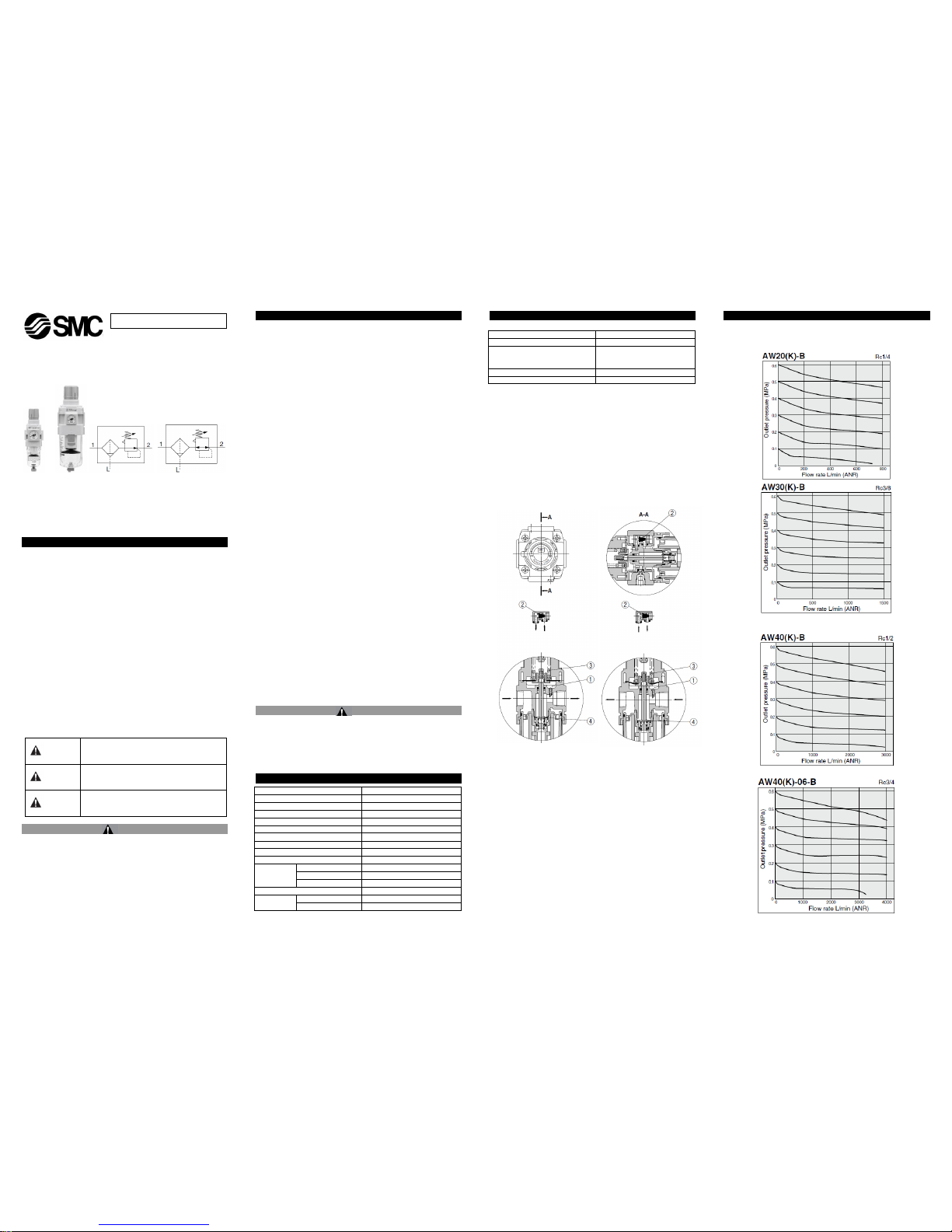
2.1 Working Principle (Filter Regulator with Backflow Function)
Figure 1 Normal Figure 2 Backflow
When the inlet pressure is higher than the regulating pressure, the
check valve ② closes and operates as a normal regulator (Figure 1).
When the inlet pressure is shut off and released, the check valve ②
opens and the pressure in the diaphragm chamber ① is released into
the inlet side (Figure 2). This lowers the pressure in the diaphragm
chamber ① and the force generated by the pressure regulator spring
③ lifts the diaphragm. The valve ④ opens through the stem, and the
outlet pressure is released to the inlet side (Figure 2).
2 Specifications – continued
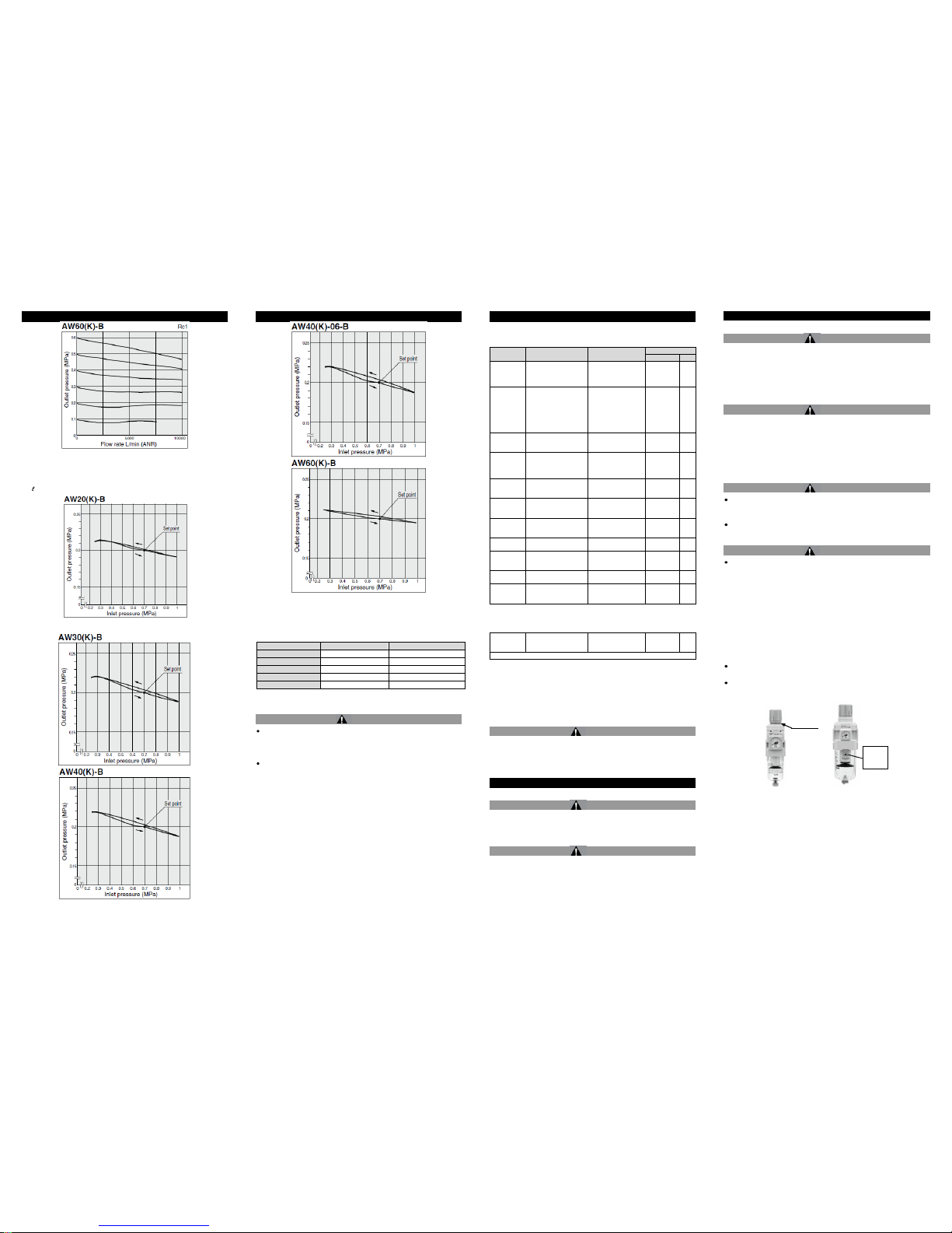
2.2 Flow characteristics
(Representative values)
Condition: Inlet pressure 0.7 MPa
ORIGINAL INSTRUCTIONS
AW-SMU06EN
Page 2 of 4
2 Specifications – continued
2.3 Pressure characteristics
(Representative values)
Conditions: Inlet pressure 0.7 MPa, Outlet pressure 0.2 MPa, Flow rate
20 /min (ANR)
2 Specifications – continued
2.4 Port size and weight
Model
Port size
Weight (kg)
AW20-B
1/8,1/4
0.20
AW30-B
1/4, 3/8
0.36
AW40-B
1/4, 3/8, 1/2
0.66
AW40-06-B
3/4
0.72
AW60-B
3/4, 1
2.05
Table 2
2.5 Design/Selection
Warning
Residual pressure disposal (outlet pressure removal) is not possible
for the AW20-B to AW60-B even though the inlet pressure is
exhausted. When the residual pressure disposal is performed, use
the filter regulator with backflow function (AW20K-B to AW60K-B).
The standard bowl for the air filter, filter regulator, and lubricator are
made of polycarbonate. Do not use in an environment where they are
exposed to or come in contact with organic solvents, chemicals,
cutting oil, synthetic oil, alkali, and thread lock solutions.
2 Specifications – continued
Effects of atmosphere of organic solvents and chemicals, and where
these elements are likely to adhere to the equipment.
Chemical data for substances causing degradation (Reference)
Type
Chemical name
Application examples
Material
Polycarbonate
Nylon
Acid
Hydrochloric acid
Sulfuric acid,
Phosphoric acid
Chromic acid
Acid washing liquid
for metals
Alkaline
Sodium hydroxide
(Caustic soda)
Potash
Calcium hydroxide
(Slack lime)
Ammonia water
Carbonate of soda
Degreasing of metals
Industrial salts
Water-soluble cutting
oil
Inorganic
salts
Sodium sulfide
Sulfate of potash
Sulfate of soda
–
Chlorine
solvents
Carbon tetrachloride
Chloroform
Ethylene chloride
Methylene chloride
Cleansing liquid for
metals
Printing ink
Dilution
Aromatic
series
Benzene
Toluene
Paint thinner
Coatings
Dry cleaning
Ketone
Acetone
Methyl ethyl ketone
Cyclohexane
Photographic film
Dry cleaning
Textile industries
Alcohol
Ethyl alcohol
IPA
Methyl alcohol
Antifreeze
Adhesives
Oil
Gasoline
Kerosene
–
Ester
Phthalic acid dimethyl
Phthalic acid diethyl
Acetic acid
Synthetic oil
Anti-rust additives
Ether
Methyl ether
Ethyl ether
Brake oil additives
Amino
Methyl amino
Cutting oil
Brake oil additives
Rubber accelerator
Others
Thread-lock fluid
Seawater
Leak tester
–
: Essentially safe :Some effects may occur : Effects will occur
Table 3
When the above factors are present, or there is some doubt, use a
metal bowl for safety.
2.6 ON indicator
If the AW-B is equipped with a gauge, the gauge will indicate the
presence of pressurised air.
Caution
Special products might have specifications different from those shown
in this section. Contact SMC for specific drawings. These drawings will
give the appropriate specification details and compliance with the safety
principles of ISO 13849, if applicable.
3 Installation
3.1 Installation
Warning
Do not install the product unless the safety instructions have been read
and understood.
3.2 Environment
Warning
Do not use in an environment where corrosive gases, chemicals, salt
water or steam are present.
Do not use in an explosive atmosphere.
Do not expose to direct sunlight. Use a suitable protective cover.
Do not install in a location subject to vibration or impact. Check the
product specifications.
Do not mount in a location exposed to radiant heat.
3 Installation – continued
3.3 Piping
Caution
Before piping make sure to clean up chips, cutting oil, dust etc.
When installing piping or fittings, ensure sealant material does not enter
inside the port. When using seal tape, leave 1.5 to 2 threads exposed
on the end of the pipe/fitting.
Tighten fittings to the specified tightening torque.
3.4 Lubrication
Caution
SMC products have been lubricated for life at manufacture, and do not
require lubrication in service.
If a lubricant is used in the system, use turbine oil Class 1 (no additive),
ISO VG32. Once lubricant is used in the system, lubrication must be
continued because the original lubricant applied during manufacturing
will be washed away.
3.5 Mounting/Adjustment
Warning
Set the regulator while verifying the displayed values of the inlet and
outlet pressure gauges. Turning the regulator knob excessively can
cause damage to the internal parts.
Do not use tools on the pressure regulator knob as this may cause
damage. It must be operated manually.
Caution
Be sure to unlock the knob before adjusting the pressure and lock it
after setting the pressure. Failure to follow this procedure can cause
damage to the knob and the outlet pressure may fluctuate.
• Pull the pressure regulator knob to unlock. (You can visually
verify this with the “orange mark” that appears in the gap.)
• Push the pressure regulator knob to lock. When the knob is not
easily locked, turn it left and right a little and then push it (when
the knob is locked, the “orange mark”, i.e., the gap will
disappear).
A knob cover is available to prevent careless operation of the knob.
Refer to the catalogue for details.
When the bowl is installed on the AW30-B to AW60-B, install them so
that the lock button lines up to the groove of the front (or the back) of
the body to avoid drop or damage of the bowl.
Orange
mark
Lock
button
 Loading...