

SMC Networks AV2000~5000-A Series, AV2000-A, AV3000-A, AV4000-A, AV5000-A Instruction Manual
AV-SMU70EN-A
Caution
Caution indicates a hazard with a low level of risk which, if
not avoided, could result in minor or moderate injury.
Warning
Warning indicates a hazard with a medium level of risk
which, if not avoided, could result in death or serious injury.
Danger
Danger indicates a hazard with a high level of risk which, if
not avoided, will result in death or serious injury.
Model
AV2000-A
AV3000-A
AV4000-A
AV5000-A
Port Size
1(P), 2(A)
1/4
3/8
1/2
3/4
1
3(R)
1/4
3/8
1/2
3/4
Pressure Gauge Port Size
1/8
Fluid
Air
Ambient/Fluid Temperature
0-50
Note 1)
Proof Pressure [MPa]
1.5
Operating Pressure Range [MPa]
0.2-1.0
Max. operating frequency
5 cycles/min not exceeding 100 cycles/day
Min. operating frequency
Once every 30 days
Min. air quality
5 µm filtration
IP rating
IP65 (DIN terminal only)
Weight [kg]
0.43
0.45
0.80
1.30
1.25
Flow characteristics
1(P)–›2(A)
C(dm3/s・bar)
9.2
13.1
19.2
34.8
41.3
b
0.36
0.27
0.32
0.66
0.34
Cv
2.4
3.1
5.1
12.6
13.7
2(A)–›3(R)
C(dm3/s・bar)
8.8
9.2
10.1
23.7
b
0.46
0.48
0.55
0.67
Cv
2.5
2.6
3.2
9.2
Impact resistance
Note 2)
1000 m/s2(11ms)
Vibration resistance
Note 3)
50 m/s2 (0.35mm)
Electrical Entry
Grommet
DIN Terminal
Coil Rated
Voltage [V]
DC
24 , 12
AC 50/60 Hz
100 , 200 , 110[115] , 220[230]
Note1)
Power
Consumption [W]
DC
0.35 (with light: 0.4)
0.35(with light: 0.45)
Allowable
DC
24V
±10% of rated voltage
12V
±10% of rated voltage
AC
100V
±10% of rated voltage
110V
Note1)
[115V]
±10% of rated voltage
[-15% to +5% of rated voltage]
200V
±10% of rated voltage
220V
Note1)
[230V]
±10% of rated voltage
[-15% to +5% of rated voltage]
Apparent Power
[VA]
AC
100V
0.78 (with light: 0.81)
0.78(with light: 0.87)
110V
[115V]
0.86 (with light: 0.89)
[0.94 (with light: 0.97)]
0.86(with light: 0.97)
[0.94(with light: 1.07)]
200V
1.18 (with light: 1.22)
1.15(with light: 1.30)
220V
[230V]
1.30 (with light: 1.34)
[1.42 (with light: 1.46)]
1.27(with light: 1.46)
[1.39(with light: 1.60)]
Surge Voltage Suppressor
Refer to Specific Product Precautions 3.7
Indicator light
LED
LED (neon bulb for AC)
ORIGINAL INSTRUCTIONS
Refer to Declaration of
Conformity for relevant
Directives
Varistor
NO.1
(-) (+)
NO.2
(+) (-)
Coil
LED
Instruction Manual
Soft Start-up Valve
Series AV2000~5000-A
The intended use of this product is to protect machine mechanism
against sudden movement during start up.
1 Safety Instructions
These safety instructions are intended to prevent hazardous situations
and/or equipment damage. These instructions indicate the level of
potential hazard with the labels of “Caution,” “Warning” or “Danger.”
They are all important notes for safety and must be followed in addition
to International Standards (ISO/IEC)
*1)
ISO 4414: Pneumatic fluid power - General rules relating to systems.
ISO 4413: Hydraulic fluid power - General rules relating to systems.
IEC 60204-1: Safety of machinery - Electrical equipment of machines.
(Part 1: General requirements)
ISO 10218-1: Manipulating industrial robots - Safety. etc.
Refer to product catalogues, Operation Manual and Handling
Precautions for SMC Products for additional information.
Keep this manual in a safe place for future reference.
*1)
, and other safety regulations.
2 Specifications
2.1 Mechanical Specification
Note 1) Please use dry air when operating at a low temperature to avoid freezing
Note 2) Two axes (horizontal and vertical) and two directions were tested and no
malfunction of the valve occurred (pulse shape: sine shape), 3 times for each
condition (pilot valve ON and OFF, test sample mounted with bracket)
Note 3) No malfunction occurred in a sweep cycle test between 10 to 150 Hz at
vibration sweep 0.35mm. The test was performed in the two axes and two
directions, 7 min per cycle (20 cycles) 20 times for each condition (pilot valve ON
and OFF)
2.2 Electrical Specification
2 Specifications - continued
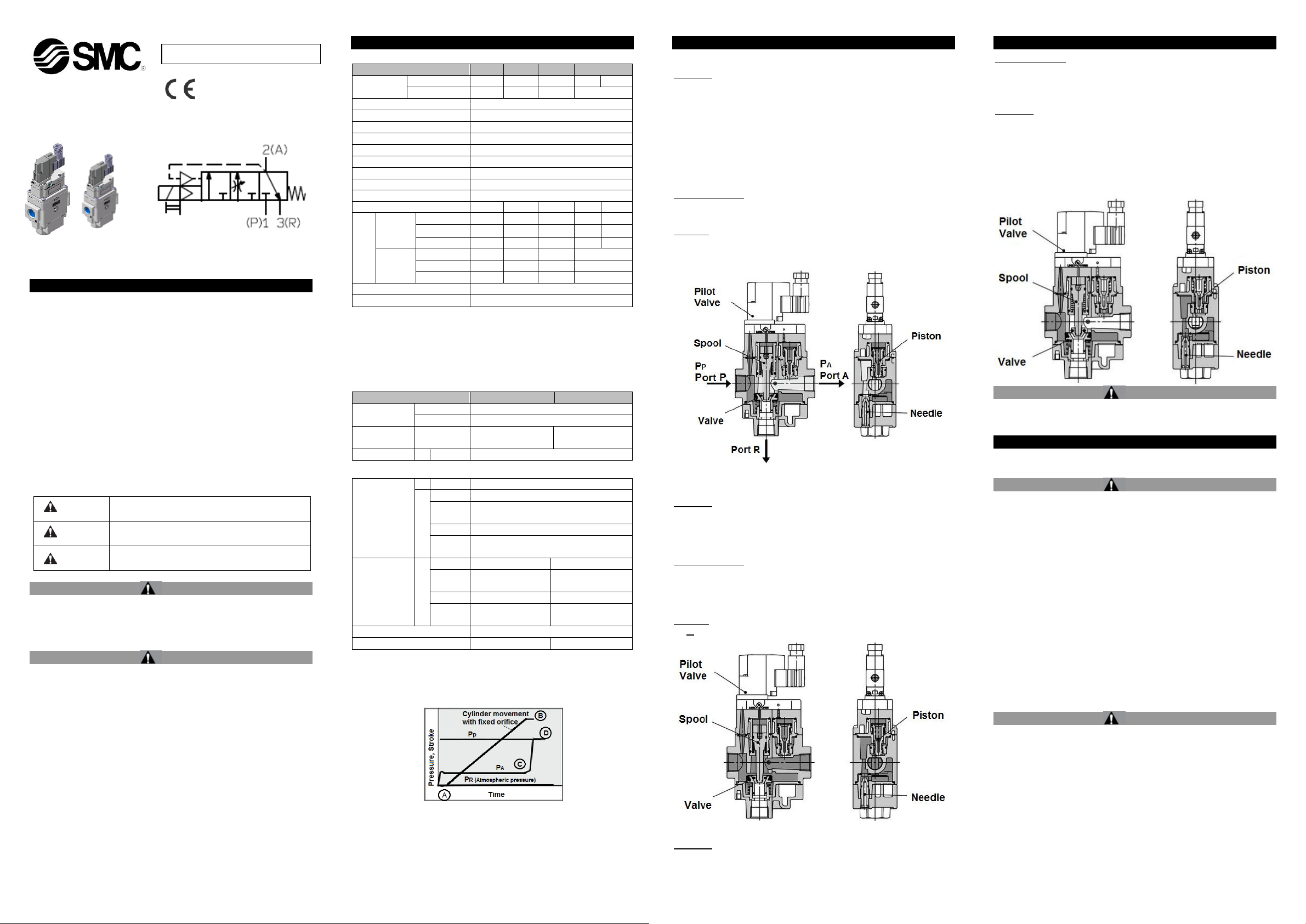
2.3.1 Low speed supply – Pilot valve ON
Operation
When the pilot valve is energised, the spool is pushed down by pilot air
and closes the main valve, closing the flow passage to port 3 (R). In
this case, force pushing the valve up is larger or equal to force pushing
the spool down. Therefore, the flow path from the valve to Port A is
also kept closed.
When the pilot valve turns on, the piston is pushed down by pilot air,
and the flow passage from the needle to Port A opens. The air pressure
whose flow rate is adjusted by the needle flows to Port A.
Cylinder actuation
The meter-in control of the needle slowly moves cylinder From A to B
(Figure 1).
Pressure
Ps>PA
Ps – pressure for switching to rapid air supply
2 Specifications - continued
Cylinder actuation - The cylinder operation is controlled by a meter-out
circuit on the cylinder side.
PP=PA
2.3.4 Quick exhaust – Pilot valve OFF
Operation
When the pilot valve is turned off, the pilot air of the spool is exhausted
from the pilot valve. The spool and the valve are returned upward due
to spring. This opens the flow pressure to port R exhausting the air
pressure on Port A.
The pilot air of the piston is also exhausted from the pilot valve and the
piston is returned upward due to the spring, closing the flow passage
from the needle.
Caution
Special products might have specifications different from those shown
in this section. Contact SMC for specific drawings.
3 Installation
3.1 Installation
Warning
Always ensure compliance with relevant safety laws and
standards.
All work must be carried out in a safe manner by a qualified person in
compliance with applicable national regulations.
Warning
When using a solenoid valve or actuator on the outlet side of this
product, implement appropriate measures to prevent potential danger
caused by actuator operation.
This product may experience air leakage (within tolerance), therefore
this valve is not suitable for holding pressure in a pressure vessel for a
long period of time.
This valve is not to be used as emergency shutoff valve. Using the
valve in such applications, take a separate measure to ensure safe
use.
Provide ventilation when using the valve in a confined area, such as in
a closed control panel. For example, install a ventilation opening, etc.
in order to prevent pressure from increasing inside of the confined
area and to release the heat generated by the valve.
The circuit designer shall ensure external cables have strain relief and
correct protective bonding in accordance with the requirements of EN
60204-1
The circuit designer shall ensure correct insulation monitoring in
accordance with the requirements of EN60204-1.
Note 1) The 110VAC and 115VAC are interchangeable. The 220V AC and 230V
AC are interchangeable as well.
Note 2) Valve state is not defined if electrical input is outside of specification
2.3 Working Principle
Initial Operation Return Stroke
Figure 1
PA – outlet pressure
PP – inlet pressure
PR – atmospheric pressure
2.3.2 High speed supply – Solenoid valve ON
Operation -When the outlet side is filled with the air supply from the
needle, PA increases. When PA reaches a certain pressure level, force
pushing the valve up is smaller than force pushing the spool down. The
valve is pushed down, opening the flow passage and is supplied to Port
A rapidly.
Cylinder actuation -When Ps<PA after the cylinder reaches B (Figure 1),
the main valve fully opens and PA increases rapidly as shown from C to
D (Figure 1) and becomes the same pressure as PP.
Ps – pressure for switching to rapid air supply
PA – outlet pressure
Pressure
Ps < PA
2.3.3 Normal operation – Pilot valve ON
Operation - The valve holds the fully open condition.
Warning
Do not install the product unless the safety instructions have
been read and understood.
Stop operation if air leakage increases or the equipment does not
operate properly.
After mounting or maintenance, etc., connect the compressed air and
power supply, then perform appropriate function and leakage tests to
ensure that the unit is mounted properly.
Operation manual/Instruction manual
Mount and operate the product after reading the manual carefully and
understanding its contents. Keep the manual in a place where it can be
referred to as necessary.
Painting and coating
Warnings or specifications printed or labelled on a product should not
be erased, removed or covered up. Please contact SMC before painting
the resin parts, as this may cause adverse effects depending on the
solvent.
Maintenance space
Allow the sufficient space for maintenance and inspection.
Warning
Confirm the specifications.
The product presented in this document is designed only for use in
compressed air systems. Do not operate at pressures or temperatures,
etc., beyond the range of specifications, as this can cause damage or
malfunction (refer to the specifications).
Please contact SMC if using for any fluid other than compressed air.
Operation of closed centre solenoid valves
Even if this product is used for closed center solenoid valves or actuator
with a load factor of 50% or more, lurching (quick extension) cannot be
prevented.
Using a regulator on the outlet side
When mounting a regulator on the outlet side (A port side), use a
residual pressure relief regulator (AR25K to 40K) or check type
Page 1 of 3
AV-SMU70EN-A
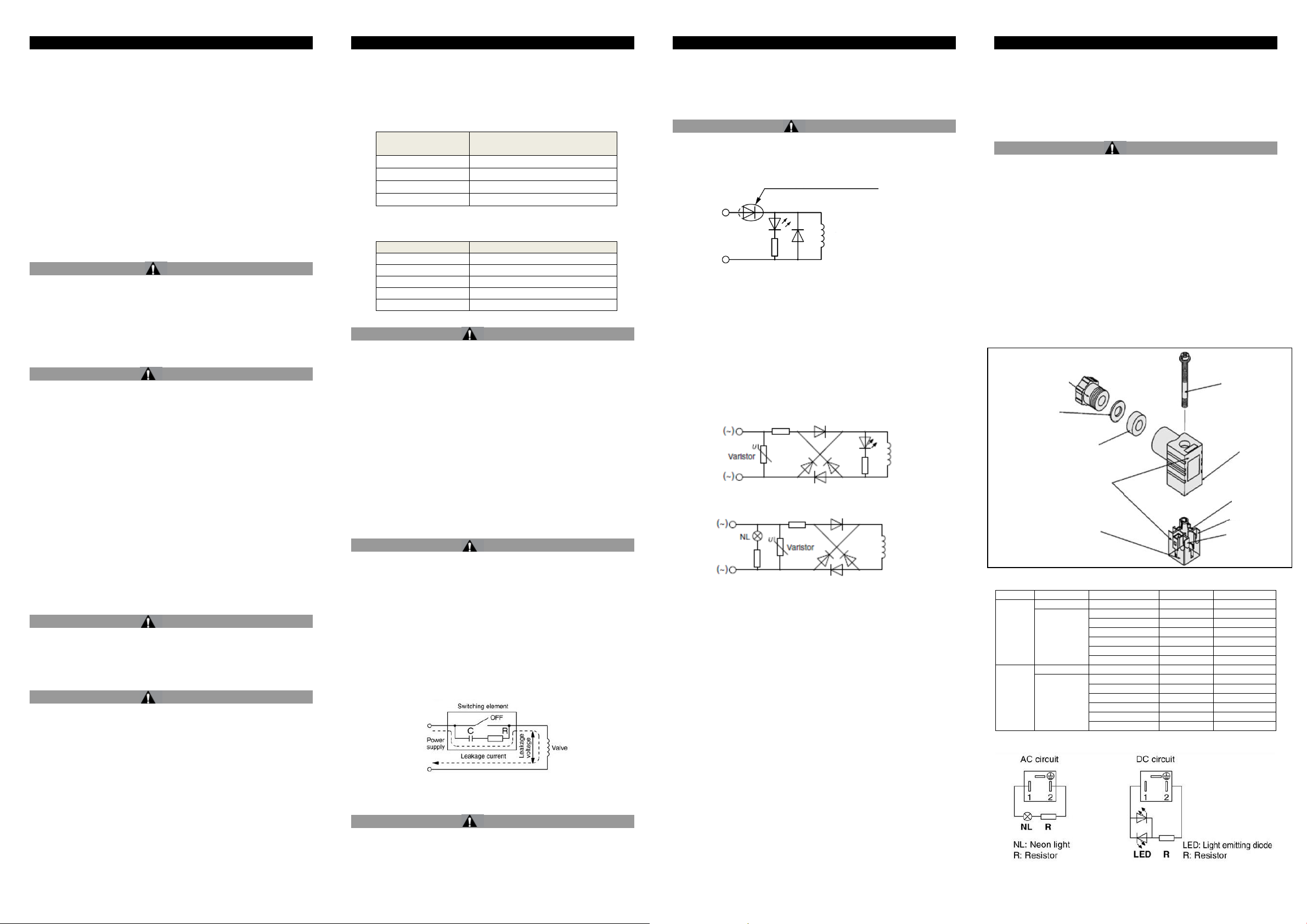
Ground nut
Tightening torque
1.65 to 2.5 N∙m
Washer
Grommet
(Rubber)
(Rating symbol)
Refer to the catalogue for DIN
connector part no.
Terminal screw
(3 locations)
Tightening torque
0.2 to 0.25 N∙m
Holding screw
Tightening torque
0.4 N∙m
Housing
(Light mounting
location)
Model
Combined sonic conductance
[dm3/(s·bar)]
AV2000-A
5
AV3000-A
22
AV4000-A
35
AV5000-A
50
Connecting threads
Proper tightening torque (N▪m)
Rc 1/4
12 to 14
Rc 3/8
22 to 24
Rc 1/2
28 to 30
Rc 3/4
28 to 30
Rc 1
36 to 38
Type
Option
Rated Voltage
Rated Symbol
Part number
“D” Type
Without light
-
-
SY100-61-1
With light
24 VDC
24 V
SY100-61-3-05
12 VDC
12 V
SY100-61-3-06
100 VAC
100 V
SY100-61-2-01
200 VAC
200 V
SY100-61-2-02
110 VAC
110 V
SY100-61-2-03
220 VAC
220 V
SY100-61-2-04
“Y” Type
Without light
-
-
SY100-82-1
With light
24VDC
24 VN
SY100-82-3-05
12VCD
12 VN
SY100-82-3-06
100VAC
100 VN
SY100-82-2-01
200VAC
200 VN
SY100-82-2-02
110VAC(115VAC)
110 VN
SY100-82-2-03
220VAC(230VAC)
220 VN
SY100-82-2-04
Coil
Coil
NL: neon bulb
Notch
Figure of
notch.
Terminal block
3 Installation - continued
regulator. With a standard regulator (AR10 to 60), the outlet side
pressure may not be released when this valve is exhausted.
Operation of solenoid valves on the outlet side
To operate solenoid valves mounted on this product’s outlet side (A port
side), make sure that the outlet side’s pressure (PA) has increased to
the pressure equal to the inlet side (PP).
Operation
The residual pressure release function of this product is for emergency
use only. Avoid using this valve in the same manner as ordinary 3 port
valves.
Using a lubricator
If mounting a lubricator, mount it on the inlet side (P port side) of this
product. If mounted on the outlet side (A port side), back flow of oil will
occur and may spurt out of the valve’s R port.
Operation for air blowing
This product cannot be operated for air blowing due to the mechanism
that switches the main valve to be fully open after the outlet side’s
pressure increases to approximately 1/2 of the inlet side.
Warning
Solenoid valve for 200, 220VAC
The AC solenoid valves with grommet have a built-in rectifier circuit in
the pilot section to operate the DC coil.
With 200V and 220 VAC pilot valves, this built-in rectifier generates
heat when energised. The surface may become hot depending on the
energised condition. To prevent burns, do not touch the solenoid valve.
3.2 Environment
Warning
Do not use in an environment where corrosive gases, chemicals, sea
water or steam are present.
Do not use in an explosive atmosphere.
Do not expose to direct sunlight. Use a suitable protective cover.
Do not install in a location subject to vibration or impact in excess of
the product’s specifications.
Do not mount in a location exposed to radiant heat that would result
3 Installation - continued
Furthermore, connect soft start-up valves to the outlet side of the F.R.L.
combination.
Inlet side piping conditions
The nominal size of the piping material’s or equipment’s bore should
be equal to or larger than the soft start-up valve’s port size. The
combined sonic conductance of the inlet side’s (P port side’s) piping or
equipment should be equal to or larger than the values below.
When the piping is restricted or the supply pressure is insufficient, the
main valve will not switch and air leakage may occur from the R port.
Tighten fittings to the specified tightening torque.
3.4 Lubrication
Caution
The valve has been lubricated for life at the factory, and does not
require any further lubrication.
If a lubricant is used in the system, refer to catalogue for details.
Once lubricant is utilized within the system, since the original lubricant
applied within the product during manufacturing will be washed away,
please continue to supply lubrication to the system. Without continued
lubrication, malfunctions could occur. If turbine oil is used, refer to the
corresponding Material Safety Data Sheet (MSDS).
Lubrication amount
If a lubricant is applied excessively, it may accumulate inside the pilot
3 Installation - continued
The compressed air containing a large amount of moisture may result in
a malfunction of the valve and other pneumatic equipment. Install an
after-cooler, air dryer or water separator or otherwise take an
appropriate measure.
3.7 Surge voltage suppressor
Caution
3.7.1 DC power supply
3.7.1.1 Grommet – standard type (with polarity)
With light/surge voltage suppressor (Z)
NOTE1: Connect correctly the lead wires to + (positive) and - (negative)
indications on the connector.
NOTE2: Solenoids, whose lead wires have been pre-wired: positive
side (+) is red and negative side (-) is black.
3.7.1.2 DIN Terminal
With light/surge voltage suppressor (DZ)
DIN terminal has no polarity.
3.7.2 AC power supply
3.7.2.1 Grommet
With light (GZ)
3 Installation - continued
2. After removing the holding screw, insert a flat head screwdriver, etc.
into the notch on the bottom of the terminal block and pry it open,
separating the terminal block and the housing.
3. Loosen the screw (slotted screws) on the terminal block. Insert the
lead cores wires into the terminals according to the connection
method, and secure the wires by re-tightening the terminal screw.
4. Secure the cord by tightening the gland nut.
Caution
When making connections, take note that using other than the
supported size (ø3.5 to ø7) heavy duty cord will not meet IP65
(enclosure) standards. Ensure to tighten the gland nut and holding
screw within their specified torque ranges.
3.8.3 Changing the entry direction
After separating the terminal block and housing, the cord entry can be
changed by attaching the housing in the desired direction (4 directions
at 90° intervals).
*When equipped with light, handle carefully to avoid damage to the light
with the lead wires in the cable.
NOTE: Plug in and pull out the connector vertically without tilting to one
side.
3.8.4 Compatible cable
Cable O.D.: ø3.5 to ø7
(Reference) 0.5mm2, 2-core or 3-core, equivalent to JIS C 3306
in temperatures in excess of the product’s specifications
Take suitable protective measures if water, oil or welding spatter is
likely to adhere to the valve.
Take measures to ensure air quality, such as by installing an
aftercooler, air dryer, or water separator. Compressed air that contains
a large amount of drainage can cause a malfunction of pneumatic
equipment such as valves. Therefore, take appropriate measures to
ensure air quality, such as by providing an aftercooler, air dryer, or
water separator.
Take suitable measures to prevent dust or noise if operating in an
environment generating dust or intrusive valve switching noise, by
providing a silencer in the R port.
Caution
Low temperature operation
Although the valve can be operated at temperature as low as 0°C,
measures should be taken to avoid solidifying or freezing drainage and
moisture.
3.3 Piping
Caution
Before connecting piping make sure to clean up chips, cutting oil, dust
etc.
When installing piping or fittings, ensure sealant material does not
enter inside the port. When using seal tape, leave 1.5-2 thread ridges
exposed on the end of the pipe/fitting.
Refer to the instruction manual/operation manual during installation
and make sure to connect to the correct supply port, etc.
F.R.L module combination
When connecting to a modular F.R.L. unit (AC20 to 60), select one of
the spacers, included amongst the accessories. However, modular
combinations with AC40-06 are not possible.
valve, causing malfunction or delayed response. Avoid using large
amount of lubricant. If it is not avoidable, use an external pilot type,
whereby supply air to the external pilot port contains no oil. This
prevents accumulation of oil inside the pilot valve.
3.5 Wiring
Caution
When electric power is connected to a solenoid valve, make sure to
apply correct voltage. Incorrect voltage may cause malfunction or coil
damage.
Check the connections.
Check if the connections are correct after completing all wiring.
External force applied to lead wire
An excessive force to the lead wire may cause wire breakage. Take
appropriate measures to avoid applying a force of 30 N or more to the
lead wire.
Voltage leakage
Particularly when using a C-R element (surge voltage suppressor) to
protect the switching element, take note that leakage current will flow
through the C-R element, increasing leakage voltage.
AC coil is 8% or less of rated voltage.
DC coil is 3% or less of rated voltage.
3.6 Air supply
Caution
Install air filters close to the valve on the upstream side.
Implement countermeasures by installing after-cooler or air dryer, or
water separator, etc.
3.7.2.2 DIN Terminal
With light (DZ) and (YZ)
NOTE1: Surge voltage suppressor of varistor has residual voltage
corresponding to the protective element and rated voltage; therefore,
protect the controller side from the surge voltage. The residual voltage
of the diode is approximately 1V.
3.8 How to use DIN terminal
3.8.1 Construction
Type “Y”
Y type DIN connector is a DIN connector that confirms to the DIN pitch
8-mm standard.
Type “D”
D type DIN connector with 9.4 mm pitch between terminals is not
interchangeable with Y type connector.
To distinguish between “Y” and “D” type DIN connector, “Y” has “N”
listed at the end of voltage symbol. For connector parts without lights,
“N” is not indicated. Refer to the name plate to distinguish.
“Y” Dimensions are the same as “D” type DIN connector.
When exchanging the pilot valve assembly only, “V115K-□D-X400”
is interchangeable with “V115K-□Y-X400”. Do not replace “V111K-
□G-X400” with “V115-□D/□Y-X400” (DIN terminal), and vice versa.
3.8.2 Connection
1. Loosen the holding screw and pull the connector out of the solenoid
valve terminal block.
3.8.5 DIN Connector part numbers
3.8.6 Circuit Diagram with light
Page 2 of 3
 Loading...