


MANAGEMENT GUIDE
SMC8124PL2
TigerSwitchTM 10/100/1000
24-Port Managed Switch with PoE


TigerSwitch 10/100/1000
Management Guide
From SMC’s Tiger line of feature-rich workgroup LAN solutions
20 Mason
Irvine, CA 92618
Phone: (949) 679-8000
May 2007
Pub. # 149100034100A
E052007-DT-R01

Information furnished by SMC Networks, Inc. (SMC) is believed to be accurate and
reliable. However, no responsibility is assumed by SMC for its use, nor for any
infringements of patents or other rights of third parties which may result from its use. No
license is granted by implication or otherwise under any patent or patent rights of SMC.
SMC reserves the right to change specifications at any time without notice.
Copyright © 2007 by
SMC Networks, Inc.
20 Mason
Irvine, CA 92618
All rights reserved. Printed in T aiwan
Trademarks:
SMC is a registered trademark; and EZ Switch, TigerStack and TigerSwitch are
trademarks of SMC Networks, Inc. Other product and company names are trademarks or
registered trademarks of their respective holders.

Limited Warranty
Limited Warranty Statement: SMC Networks, Inc. (“SMC”) warrants its products to be
free from defects in workmanship and materials, under normal use and service, for the
applicable warranty term. All SMC products carry a standard 90-day limited warranty from
the date of purchase from SMC or its Authorized Reseller. SMC may , at i ts own discretion,
repair or replace any product not operating as warranted with a similar or functionally
equivalent product, during the applicable warranty term. SMC will endeavor to repair or
replace any product returned under warranty within 30 days of receipt of the product.
The standard limited warranty can be upgraded to a Limited Lifetime* warranty by
registering new products within 30 days of purchase from SMC or its Authorized Reseller.
Registration can be accomplished via the enclosed product registration card or online via
the SMC Web site. Failure to register will not affect the standard limited warranty. The
Limited Lifetime warranty covers a product during the Life of that Product, which is
defined as the period of time during which the product is an “Active” SMC product. A
product is considered to be “Active” while it is listed on the current SMC price list. As new
technologies emerge, older technologies become obsolete and SMC will, at its discretion,
replace an older product in its product line with one that incorporates these newer
technologies. At that point, the obsolete product is discontinued and is no longer an
“Active” SMC product. A list of discontinued products with their respective dates of
discontinuance can be found at:
http://www.smc.com/index.cfm?action=customer_service_warranty.
All products that are replaced become the property of SMC. Replacement products may
be either new or reconditioned. Any replaced or repaired product carries either a 30-day
limited warranty or the remainder of the initial warranty, whichever is longer. SMC is not
responsible for any custom software or firmware, configuration information, or memory
data of Customer contained in, stored on, or integrated with any products returned to
SMC pursuant to any warranty. Products returned to SMC should have any
customer-installed accessory or add-on components, such as expansion modules,
removed prior to returning the product for replacement. SMC is not responsible for these
items if they are returned with the product.
Customers must contact SMC for a Return Material Authorization number prior to
returning any product to SMC. Proof of purchase may be required. Any product returned
to SMC without a valid Return Material Authorization (RMA) number clearly marked on
the outside of the package will be returned to customer at customer’s expense. For
warranty claims within North America, please call our toll-free customer support number
at (800) 762-4968. Customers are responsible for all shipping charges from their facility to
SMC. SMC is responsible for return shipping charges from SMC to customer.
WARRANTIES EXCLUSIVE: IF AN SMC PRODUCT DO ES NOT OPERATE AS
WARRANTED ABOVE, CUSTOMER’S SOLE REMEDY SHALL BE REPAIR OR
REPLACEMENT OF THE PRODUCT IN QUESTION, AT SMC’S OPTION. THE
FOREGOING WARRANTIES AND REMEDIES ARE EXCLUSIVE AND ARE IN LIEU OF
ALL OTHER WARRANTIE S O R CO NDITIONS , EX PR E SS O R IM PLIED, EITHER IN
FACT OR BY OPERATION OF LAW, STATUTORY OR OTHERWISE, INCLUDING
WARRANTIES OR CONDITIONS OF MERCHANTABILITY AND FITNESS FOR A
PARTICULAR PURPOSE. SMC NEITHER ASSUMES NOR AUTHORIZES ANY OTHER
PERSON TO ASSUME FOR IT ANY OTHER LIABILITY IN CONNECTION WITH THE
SALE, INSTALLATION, MAINTENANCE OR USE OF ITS PRODUCTS. SMC SHALL
i

NOT BE LIABLE UNDER THIS WARRANTY IF ITS TESTING AND EXAMINATION
DISCLOSE THE ALLEGED DEFECT IN THE PRODUCT DOES NOT EXIST OR WAS
CAUSED BY CUSTOMER’S OR ANY THIRD PERSON’S MISUSE, NEGLECT,
IMPROPER INSTALLATION OR TESTING, UNAUTHORIZED ATTEMPTS TO REPAIR,
OR ANY OTHER CAUSE BEYOND THE RANGE OF THE INTENDED USE, OR BY
ACCIDENT, FIRE, LIGHTNING, OR OTHER HAZARD.
LIMITATION OF LIABILITY: IN NO EVENT, WHETHER BASED IN CONTRACT OR
TORT (INCLUDING NEGLIGENCE), SHALL SMC BE LIABLE FOR INCIDENTAL,
CONSEQUENTIAL, INDIRECT, SPECIAL, OR PUNITIVE DAMAGES OF ANY KIND, OR
FOR LOSS OF REVENUE, LOSS OF BUSINESS, OR OTHER FINANCIAL LOSS
ARISING OUT OF OR IN CONNECTION WITH THE SALE, INSTALLATION,
MAINTENANCE, USE, PERFORMANCE, FAILURE, OR INTERRUPTION OF ITS
PRODUCTS, EVEN IF SMC OR ITS AUTHORIZED RESELLER HAS BEEN ADVISED
OF THE POSSIBILITY OF SUCH DAMAGES.
SOME STATES DO NOT ALLOW THE EXCLUSION OF IMPLIED WARRANTIES OR
THE LIMITATION OF INCIDENTAL OR CONSEQUENTIAL DAMAGES FOR
CONSUMER PRODUCTS , SO THE ABOVE LIM ITATIONS AND EX CL US I O N S MAY
NOT APPLY TO YOU. THIS WARRANTY GIVES YOU SPECIFIC LEGAL RIGHTS,
WHICH MAY VARY FROM STATE TO STATE. NOTHING IN THIS WARRANTY SHALL
BE TAKEN TO AFFECT YOUR STATUTORY RIGHTS.
* SMC will provide warranty service for one year following discontinuance from the active
SMC price list. Under the limited lifetime warranty, internal and external power supplies,
fans, and cables are covered by a standard one-year warranty from date of purchase.
SMC Networks, Inc.
20 Mason
Irvine, CA 92618
ii

Contents
Chapter 1: Introduction 1-1
Key Features 1-1
Description of Software Features 1-2
System Defaults 1-5
Chapter 2: Initial Configuration 2-1
Connecting to the Switch 2-1
Configuration Options 2-1
Required Connections 2-2
Remote Connection s 2-3
Basic Configuration 2-3
Console Connection 2-3
Setting Passwords 2-4
Setting an IP Address 2-4
Manual Configuration 2-5
Dynamic Configuration 2-5
Enabling SNMP Management Access 2-6
Community Strings (for SNMP version 1 and 2c clients) 2-7
Trap Receivers 2-7
Configuring Access for SNMP Version 3 Clients 2-8
Saving Configuration Settings 2-8
Managing System Files 2-9
Chapter 3: Configuring the Switch 3-1
Using the Web Interface 3-1
Navigating the Web Browser Interface 3-2
Home Page 3-2
Configuration Options 3-2
Panel Displa y 3-3
Main Menu 3-3
Basic Configuration 3-10
Displaying System Information 3-10
Displaying Switch Hardware/Software Versions 3-11
Displaying Bridge Extension Capabilities 3-12
Setting the Switch’s IP Address 3-14
Manual Configuration 3-15
Using DHCP/BOOTP 3-16
Enabling Jumbo Frames 3-17
iii

Contents
Managing Firmware 3-18
Downloading System Software from a Server 3-18
Saving or Restoring Configuration Settings 3-20
Downloading Configuration Settings from a Server 3-21
Console Port Settings 3-22
Telnet Settings 3-24
Configuring Event Logging 3-26
Displayi ng Log Messages 3-26
System Log Configuration 3-27
Remote Log Configuration 3-29
Simple Mail Transfer Protocol 3-30
Resetting the System 3-32
Setting the System Clock 3-32
Configuring SNTP 3-32
Setting the Time Zone 3-33
Simple Network Management Protocol 3-34
Enabling the SNMP Agent 3-36
Setting Community Access Strings 3-36
Specifying Trap Managers and Trap Types 3-37
Configuring SNMPv3 Management Access 3-39
Setting the Local Engine ID 3-40
Specifying a Remote Engine ID 3-40
Configuring SNMPv 3 Users 3-41
Configuring Remote SN MPv 3 Users 3-43
Configuring SNMPv 3 Groups 3-45
Setting SNMPv3 Views 3-48
User Authenticatio n 3-50
Configuring User Accounts 3-50
Configuring Local/Remote Logon Authentication 3-51
Configuring HTTPS 3-54
Replacing the Defau lt Secure-s ite Cert ific at e 3-56
Configuring the Secure S hell 3-56
Configuring the SSH settings 3-58
Generating the Host Key Pair 3-59
Generating the User Public Key Pair 3-61
Configuring Port Security 3-63
Configuring 8 02.1X Port Authentication 3-64
Displaying 802.1X Global Settings 3-66
Configuring 802.1X Global Settings 3-66
Configuring Port Settings for 802.1X 3-67
Displaying 802.1X Statistics 3-70
Access Control Lists 3-72
Configuring Access Control Lists 3-72
Setting the ACL Name and Type 3-72
Configuring a Standard IP ACL 3-73
iv

Contents
Configuring an Exte nde d IP ACL 3-74
Configuring a MAC ACL 3-77
Binding a Port to an Access Control List 3-78
Filtering Management Access 3-79
Port Configuration 3-81
Displaying Connection Status 3-81
Configuring Interface Connections 3-83
Creating Trunk Groups 3-85
Statically Configuring a Trunk 3-86
Enabling LACP on Selected Ports 3-88
Configuring LACP Param ete rs 3-89
Displaying LACP Port Counters 3-91
Displaying LACP S ettings and Status for the Local Side 3-92
Displaying LACP Settings and Status for the Remote Side 3-94
Setting Broadcast Storm Thresholds 3-96
Configuring Port Mirroring 3-97
Configuring Rate Limits 3-98
Rate Limit Configuration 3-98
Showing Port Statistics 3-99
Power ov er Ethernet Set tings 3-104
Switch Power Status 3-105
Setting a Switch Power Budget 3-106
Displaying Port Power Status 3-106
Configuring Port PoE Power 3-107
Address Table Settings 3-108
Setting Static Addresses 3-108
Displaying the Address Table 3-109
Changing the Aging Time 3-110
Spanning Tree Algorithm Configuration 3-111
Displaying Global Settings 3-112
Configuring Global Settings 3-114
Displaying Interface Settings 3-118
Configuring Interface Settings 3-121
VLAN Configuration 3-123
Overview 3-123
Assigning Ports to VLANs 3-123
Forwarding Tagged/Untagged Frames 3-125
Displaying Basic VLAN Information 3-126
Displaying Current VLANs 3-126
Creating VLANs 3-128
Adding Static Members to VLANs (VLAN Index) 3-129
Adding Static Members to VLANs (Port Index) 3-131
Configuring V LAN Behavior f or Interfaces 3-132
Configuring Private VLANs 3-133
Displaying Current Private VLANs 3-134
v

Contents
Configuring Private VLANs 3-135
Associating VLANs 3-136
Displaying Private VLAN Interface Information 3-136
Configuring Private VLAN Interfaces 3-137
Configuring Protocol VLANs 3-139
Configuring Protoco l VLAN Basic Setting s 3-139
Configuring Protoco l VLAN System 3-140
LLDP 3-140
Configuring Basic LLDP Time Information 3-140
Configuring LLDP Port and Trunk Information 3-141
Displaying LLDP Local and Remote Device Inform ation 3-143
Class of Service Configuration 3-145
Setting the Default Priority for Interfaces 3-146
Mapping CoS Values to Egress Queues 3-147
Enabling CoS 3-149
Selecting the Queue Mode 3-149
Setting the Service Weight for Traffic Classes 3-150
Mapping Layer 3/4 Priorities to CoS Values 3-151
Selecting IP DSCP Priority 3-151
Mapping DSCP Priority 3-152
Quality of Service 3-153
Configuring Quality of Service Parameters 3-154
Configuring a Class Map 3-154
Creating QoS Policies 3-157
Attaching a Policy Map to Ingress Queues 3-160
Multicast Filtering 3-161
IGMP Protocol 3-161
Layer 2 IGMP (Snooping and Query) 3-162
Configuring IGMP Snooping and Query Parameters 3-162
Displaying Interfaces Attached to a Multicast Router 3-164
Specifying Static Interfaces for a Multicast Router 3-165
Displaying Port Members of Multicast Services 3-166
Assigning Ports to Multicast Services 3-167
Multicast VLAN Registration 3-168
Configuring Global MVR Settings 3-169
Displaying MVR Interface Status 3-170
Displaying Port Members of Multicast Groups 3-171
Configuring MVR Interface Status 3-172
Assigning Static Multicast Gro ups to Interfac es 3-174
DHCP Snooping 3-175
DHCP Snooping Configuration 3-176
DHCP Snooping VLAN Configuration 3-176
DHCP Snooping Information Option Configuration 3-177
DHCP Snooping Port Configuration 3-178
DHCP Snooping Binding Information 3-179
vi

Contents
IP Source Guard 3-180
IP Source Guard Port Configuration 3-180
Static IP Source Guard Binding Configuration 3-181
Dynamic IP Source Guard Binding Information 3-182
Switch Clustering 3-183
Cluster Configurati on 3-184
Cluster Member Configuration 3-185
Cluster Member Informati on 3-185
Cluster Candidate Info rma tion 3-186
UPnP 3-187
UPnP Configuration 3-188
Chapter 4: Command Line Interf ace 4-1
Using the Command Line Interface 4-1
Accessing the CLI 4-1
Console Connection 4-1
Telnet Connection 4-1
Entering Commands 4-3
Keywords and Arguments 4-3
Minimum Abbreviation 4-3
Command Completion 4-3
Getting Help on Commands 4-3
Showing Commands 4-3
Partial Keyword Lookup 4-5
Negating the Effect of Commands 4-5
Using Command History 4-5
Understanding Command Modes 4-5
Exec Commands 4-6
Configuration Commands 4-6
Command Line Processing 4-7
Command Groups 4-8
Line Commands 4-9
line 4-10
login 4-11
password 4-12
timeout login response 4-13
exec-timeout 4-13
password-thresh 4-14
silent-time 4-15
databits 4-15
parity 4-16
speed 4-16
stopbits 4-17
disconnect 4-17
vii

Contents
show line 4-18
General Commands 4-19
enable 4-19
disable 4-20
configure 4-20
show history 4-21
reload 4-21
end 4-22
exit 4-22
quit 4-23
System Management Commands 4-23
Device Designation Commands 4-24
prompt 4-24
hostname 4-25
User Access Commands 4-25
username 4-25
enable password 4-26
IP Filter Commands 4-27
management 4-27
show management 4-28
Web Server Commands 4-29
ip http port 4-29
ip http server 4-30
ip http secure-server 4-30
ip http secure-port 4-31
Telnet Server Commands 4-32
ip telnet server 4-32
ip telnet server port 4-32
Secure Shell Commands 4-33
ip ssh server 4-35
ip ssh timeout 4-36
ip ssh authentication-retries 4-37
ip ssh server-key size 4-37
delete public-k ey 4-38
ip ssh crypto host-key generate 4-38
ip ssh crypto zeroize 4-39
ip ssh save host-key 4-39
show ip ssh 4-40
show ssh 4-40
show public-key 4-41
Event Logging Commands 4-43
logging on 4-43
logging history 4-44
logging host 4-45
logging facility 4-45
viii

Contents
logging trap 4-46
clear logging 4-46
show logging 4-47
show log 4-48
SMTP Alert Commands 4-49
logging sendmail host 4-49
logging sendmail level 4-50
logging sendmail source-email 4-51
logging sendmail destination-email 4-51
logging sendmail 4-52
show logging sendmail 4-52
Time Commands 4-53
sntp client 4-53
sntp server 4-54
sntp poll 4-55
show sntp 4-55
clock timezone 4-56
calendar set 4-56
show calendar 4-57
System Status Commands 4-57
show startup-config 4-57
show running-config 4-59
show system 4-60
show users 4-61
show version 4-62
Frame Size Commands 4-63
jumbo frame 4-63
Flash/File Commands 4-64
copy 4-64
delete 4-67
dir 4-67
whichboot 4-68
boot system 4-69
Authent ication C ommands 4-70
Authentication Sequence 4-70
authentication login 4-70
authentication enable 4-71
RADIUS Client 4-72
radius-ser ver host 4-72
radius-server port 4-73
radius-ser ver ke y 4-74
radius-server retransmit 4-74
radius-server tim eo ut 4-75
show radi us-server 4-75
TACACS+ Client 4-76
ix

Contents
tacacs-server host 4-76
tacacs-server port 4-76
tacacs-server key 4-77
show tacacs-server 4-77
Port Security Commands 4-78
port security 4-78
802.1X Port Authentication 4-80
dot1x system-auth-control 4-80
dot1x default 4-81
dot1x max-req 4-81
dot1x port-control 4-81
dot1x operation-mode 4-82
dot1x re-authenticate 4-83
dot1x re-authentication 4-83
dot1x timeout quiet-period 4-83
dot1x timeout re-authperiod 4-84
dot1x timeout tx-period 4-84
show dot1x 4-85
Access Control List Commands 4-88
IP ACLs 4-89
access-list ip 4-89
permit, deny (Standard ACL) 4-90
permit, deny (Extended ACL) 4-91
show ip access-list 4-92
ip access-group 4-92
show ip access-group 4-93
map access-list ip 4-93
show map access-list i p 4-94
ACL Information 4-95
show access-list 4-95
show access-group 4-95
SNMP Commands 4-96
snmp-server 4-96
show snmp 4-97
snmp-server community 4-98
snmp-server contact 4-99
snmp-server location 4-99
snmp-server host 4-100
snmp-server enable traps 4-102
snmp-server engine-id 4-103
show snmp engine-id 4-104
snmp-server view 4-105
show snmp view 4-105
snmp-server group 4-106
show snmp group 4-107
x

Contents
snmp-server user 4-109
show snmp user 4-110
Interface Commands 4-111
interface 4-111
description 4-112
speed-duplex 4-112
negotiation 4-113
capabilities 4-114
flowcontrol 4-115
shutdown 4-116
clear counters 4-116
show interfaces status 4-117
show interfaces counters 4-118
show interfaces switchport 4-119
Broadcast Commands 4-121
broadcast packet-rate 4-121
switchport broadcast 4-121
Mirror Port Commands 4-122
port monitor 4-122
show port monitor 4-123
Rate Limit Commands 4-124
rate-limit 4-124
Link Aggregation Commands 4-125
channel-group 4-126
lacp 4-127
lacp system-priority 4-128
lacp admin-key (Ethernet Interface) 4-129
lacp admin-key (Port Channel) 4-130
lacp port-priority 4-131
show lacp 4-131
Address T able Commands 4-135
mac-ad dress-t able static 4-135
clear mac-addre ss- tab le dyn am ic 4-136
show mac-address-table 4-137
mac-address-table aging-time 4-138
show mac-address-table aging-time 4-138
Spanning Tree Commands 4-139
spanning-tree 4-139
spanning-tree mode 4-140
spanning-tree forward-time 4-141
spanning-tree hello-time 4-142
spanning-tree max-age 4-142
spanning-tree priority 4-143
spanning-tree pathcost method 4-144
spanning-tree transmission-limit 4-144
xi

Contents
spanning-tree spanning-disabled 4-145
spanning-tree cost 4-145
spanning-tree port-priority 4-146
spanning-tree edge-port 4-147
spanning-tree portfast 4-148
spanning-tree link-type 4-148
spanning-tree protocol-migration 4-149
show spanning-tree 4-150
VLAN Commands 4-152
Editing VLAN Groups 4-152
vlan database 4-152
vlan 4-153
Configuring VLAN Interfaces 4-154
interface vlan 4-154
switchport mode 4-155
switchport acceptable-frame-types 4-155
switchpo rt ingress-filtering 4-156
switchpo rt native vlan 4-157
switchpo rt allowed vlan 4-157
switchpo rt forbidden vlan 4-158
Displaying VLAN Information 4-159
show vlan 4-159
Configuring Private VLANs 4-160
private-vlan 4-161
private vlan association 4-162
switchpo rt mode private-vlan 4-162
switchport private-vlan host-association 4-163
switchport private-vlan mapping 4-164
show vlan private-vlan 4-164
GVRP and Bridge Extension Commands 4-165
bridge-ext gvrp 4-165
show bridge-ext 4-166
switchport gvrp 4-166
show gv rp configurati on 4-167
garp timer 4-167
show garp timer 4-168
Priority Comman ds 4 -16 9
Priority Commands (Layer 2) 4-170
queue mode 4-170
switchport priority default 4-171
queue bandwidth 4-172
queue cos-map 4-172
show queue mode 4-173
show queue bandwidth 4-174
show queue cos-map 4-174
xii

Contents
Priority Commands (Layer 3 and 4) 4-175
map ip dscp (Global Configuration) 4-175
map ip dscp (Interface Configuration) 4-176
show map ip dscp 4-177
Multicast Filtering Comm ands 4-178
IGMP Snooping Commands 4-178
ip igmp snooping 4-178
ip igmp snooping vlan static 4-179
ip igmp snooping version 4-179
ip igmp snooping immediate-leave 4-180
show ip igmp snooping 4-180
show mac-address-table multicas t 4-181
IGMP Query Commands (Layer 2) 4-182
ip igmp snooping querier 4-182
ip igmp snooping query-count 4-182
ip igmp snooping query-interval 4-183
ip igmp snooping query-max-response-time 4-184
ip igmp snooping router-port-expire-time 4-185
Static Multicast Routing Commands 4-185
ip igmp snooping vlan mrouter 4-185
show ip igmp snoopi ng mrouter 4-186
IGMP Filtering and Throttling Commands 4-187
ip igmp filter (Global Configuration) 4-187
ip igmp profile 4-188
permit, deny 4-189
range 4-189
ip igmp filter (Interface Configuration) 4-190
ip igmp max-groups 4-191
ip igmp max-groups action 4-191
show ip igmp filter 4-192
show ip igmp profile 4-193
show ip igmp thrott le inter face 4-193
Multicast VLAN Registration Commands 4-194
mvr (Global Configuration) 4-194
mvr (Interface Configuration) 4-195
show mvr 4-197
LLDP 4-199
lldp transmit-interval 4-201
lldp transmit-delay 4-201
lldp transmit-hold 4-202
lldp reinit-delay 4-202
lldp notification-int erval 4-203
lldp 4-204
lldp basic-tlv management-address 4-204
lldp basic-tlv description 4-205
xiii

Contents
lldp basic-tlv system-capabilities 4-206
lldp basic-tlv system-description 4-206
lldp basic-tlv system-name 4-207
lldp notificat ion 4-207
lldp dot1-tlv port-vlan-id 4-208
lldp dot1-tlv port-protocol-vlan-id 4-209
lldp dot1-tlv vlan-name 4-209
lldp dot1-tlv protocol-identity 4-210
lldp dot3-tlv mac-phy 4-210
lldp dot3-tlv link-aggregation 4-211
lldp dot3-tlv power-via-mdi 4-211
lldp dot3-tlv maximum- frame-size 4-212
show lldp config 4-212
show lldp info local-device 4-213
show lldp info remote-device 4-214
show lldp info statistics 4-215
UPnP 4-216
UPnP Configuration 4-216
upnp device 4-217
upnp device ttl 4-217
upnp device advertise duration 4-218
show upnp 4-218
IP Interface Commands 4-219
Basic IP Configuration 4-219
ip address 4-219
ip dhcp restart 4-220
ip default-gateway 4-221
show ip interfac e 4-222
show ip redir ects 4-222
ping 4-222
IP Source Guard Commands 4-223
ip source-guard 4-224
ip source-guard binding 4-225
show ip source-gua rd 4-227
show ip source-guard binding 4-227
DHCP Snooping Commands 4-227
ip dhcp snooping 4-228
ip dhcp snooping vl an 4-230
ip dhcp snooping trust 4-230
ip dhcp snooping verify mac-address 4-231
ip dhcp snooping information option 4-232
ip dhcp snooping information policy 4-233
ip dhcp snooping database flash 4-233
show ip dhcp snooping 4-234
show ip dhcp snooping binding 4-234
xiv

Contents
Switch Cluster Commands 4-235
cluster 4-235
cluster commander 4-236
cluster ip-pool 4-236
cluster member 4-237
rcommand 4-238
show cluster 4-238
show clust er members 4-23 9
show cluster candidates 4-239
Appendix A: Software Specifications A-1
Software Features A-1
Management Features A-2
Standards A-2
Management Info rma t io n Bases A-3
Appendix B: Troubleshooting B-1
Problems Accessing the Management Interface B-1
Using System Logs B-2
Glossary
Index
xv

Contents
xvi

Tables
Table 1-1 Key Features 1-1
Table 1-2 System Defaults 1-5
Table 3-1 Configuration Options 3-2
Table 3-2 Main Menu 3-3
Table 3-3 Logging Levels 3-27
Table 3-4 SNMPv3 Security Models and Levels 3-35
Table 3-5 Supported Notification Messages 3-45
Table 3-6 HTTPS Support 3-55
Table 3-7 802.1X Statistics 3-70
Table 3-8 LACP Port Counter Information 3-91
Table 3-9 LACP Settings 3-92
Table 3-10 LACP Remote Side Settings 3-94
Table 3-11 Port Statistics 3-100
Table 3-12 Egress Queue Priority Mapping 3-147
Table 3-13 CoS Priority Levels 3-147
Table 3-14 Mapping DSCP Priority 3-152
Table 4-1. Command Modes 4-5
Table 4-2. Configuration Commands 4-7
Table 4-3. Keystroke Commands 4-7
Table 4-4. Command Group Index 4-8
Table 4-5. Line Command Syntax 4-9
Table 4-6. General Commands 4-19
Table 4-7. System Management Commands 4-23
Table 4-8. Device Designation Commands 4-24
Table 4-9. User Access Commands 4-25
Table 4-10. Default Login Settings 4-26
Table 4-11. IP Filter Commands 4-27
Table 4-12. Web Server Command 4-29
Table 4-13. HTTPS System Support 4-31
Table 4-14. Telnet Server Commands 4-32
Table 4-15. Secure Shell Commands 4-33
Table 4-16. show ssh - display description 4-41
Table 4-17. Event Logging Commands 4-43
Table 4-18. Logging Levels 4-44
Table 4-19. show logging flash/ram - display description 4-48
Table 4-20. show logging trap - display description 4-48
Table 4-21. SMTP Alert Commands 4-49
Table 4-22. Time Commands 4-53
Table 4-23. System Status Commands 4-57
Table 4-24. Frame Size Commands 4-63
Table 4-25. Flash/File Commands 4-64
Table 4-26. File Directory Information 4-68
xvii

Tables
Table 4-27. Authentication Commands 4-70
Table 4-28. Authentication Sequence 4-70
Table 4-29. RADIUS Client Commands 4-72
Table 4-30. TACACS+ Client Commands 4-76
Table 4-31. Port Security Commands 4-78
Table 4-32. 802.1X Port Authentication Commands 4-80
Table 4-33. Access Control List Commands 4-88
Table 4-34. IP ACL Commands 4-89
Table 4-35. Egress Queue Priority Mapping 4-94
Table 4-36. ACL Information 4-95
Table 4-37. SNMP Commands 4-96
Table 4-38. show snmp engine-id - display description 4-104
Table 4-39. show snmp view - display description 4-106
Table 4-40. show snmp group - display description 4-108
Table 4-41. show snmp user - display description 4-110
Table 4-42. Interface Commands 4-111
Table 4-43. show interfaces switchport - display description 4-120
Table 4-44. Broadcast Commands 4-121
Table 4-45. Mirror Port Commands 4-122
Table 4-46. Rate Limit Commands 4-124
Table 4-47. Link Aggregation Commands 4-125
Table 4-48. show lacp counters - display description 4-132
Table 4-49. show lacp internal - display description 4-133
Table 4-50. show lacp neighbors - display description 4-134
Table 4-52. Address Table Commands 4-135
Table 4-51. show lacp sysid - display description 4-135
Table 4-53. Spanning Tree Commands 4-139
Table 4-54. VLAN Commands 4-152
Table 4-55. Editing VLAN Groups 4-152
Table 4-56. Configuring VLAN Interfaces 4-154
Table 4-57. Displaying VLAN Information 4-159
Table 4-58. Private VLAN Commands 4-160
Table 4-59. GVRP and Bridge Extension Commands 4-165
Table 4-60. Priority Commands 4-169
Table 4-61. Priority Commands (Layer 2) 4-170
Table 4-62. Default CoS Priority Levels 4-173
Table 4-63. Priority Commands (Layer 3 and 4) 4-175
Table 4-64. Mapping IP DSCP to CoS Values 4-176
Table 4-65. Multicast Filtering Commands 4-178
Table 4-66. IGMP Snooping Commands 4-178
Table 4-67. IGMP Query Commands (Layer 2) 4-182
Table 4-68. Static Multicast Routing Commands 4-185
Table 4-69. IGMP Filtering and Throttling Commands 4-187
Table 4-70. Multicast VLAN Registration Commands 4-194
Table 4-71. show mvr - display description 4-198
xii

Tables
Table 4-72. show mvr interface - display description 4-198
Table 4-73. show mvr members - display description 4-199
Table 4-74. LLDP Commands 4-199
Table 4-75. UPnP Commands 4-216
Table 4-76. IP Interface Commands 4-219
Table 4-77. IP Source Guard Commands 4-224
Table 4-78. DHCP Snooping Commands 4-227
Table 4-79. Switch Cluster Commands 4-235
Table 2-1. Troubleshooting Chart B-1
xii

Figures
Figure 3-1. Homepage 3-2
Figure 3-2. Panel Display 3-3
Figure 3-3. System Information 3-10
Figure 3-4. Switch Information 3-12
Figure 3-5. Bridge Extension Configuration 3-13
Figure 3-6. Manual IP Configuration 3-15
Figure 3-7. DHCP IP Configuration 3-16
Figure 3-8. Enabling Jumbo Frames 3-17
Figure 3-9. Copy Firmware 3-19
Figure 3-10. Setting the Startup Code 3-19
Figure 3-11. Deleting Files 3-19
Figure 3-12. Downlo ading Configuration Settings for Startup 3-21
Figure 3-13. Setting the Startup Configuration Settings 3-21
Figure 3-14. Console Port Setting 3-23
Figure 3-15. Enabling Telnet 3-25
Figure 3-16. Displaying Logs 3-27
Figure 3-17. System Logs 3-28
Figure 3-18. Remote Logs 3-29
Figure 3-19. Enabling and Configuring SMTP 3-31
Figure 3-20. Resetting the System 3-32
Figure 3-21. SNTP Configuration 3-33
Figure 3-22. Setting the Time Zone 3-34
Figure 3-23. Enabling the SNMP Agent 3-36
Figure 3-24. Configuring SNMP Community Strings 3-37
Figure 3-25. Configuring SNMP Trap Managers 3-39
Figure 3-26. Setting an Engine ID 3-40
Figure 3-27. Setting an Engine ID 3-41
Figure 3-28. Configuring SNMPv3 Users 3-42
Figure 3-29. Configuring Remote SNMPv3 Users 3-44
Figure 3-30. Configuring SNMPv3 Groups 3-47
Figure 3-31. Configuring SNMPv3 Views 3-49
Figure 3-32. Access Levels 3-51
Figure 3-33. Authentication Settings 3-53
Figure 3-34. HTTPS Settings 3-55
Figure 3-35. SSH Server Settings 3-59
Figure 3-36. SSH Host-Key Settings 3-60
Figure 3-37. SSH User Public-Key Settings 3-62
Figure 3-38. Configuring Port Security 3-64
Figure 3-39. 802.1X Global Information 3-66
Figure 3-40. 802.1X Global Configuration 3-67
Figure 3-41. 802.1X Port Configuration 3-68
Figure 3-42. Displaying 802.1X Port Statistics 3-71
xx

Figures
Figure 3-43. Naming and Choosing ACLs 3-73
Figure 3-44. Configuring Standard IP ACLs 3-74
Figure 3-45. Configuring Extended IP ACLs 3-76
Figure 3-46. Configuring MAC ACLs 3-78
Figure 3-47. Mapping ACLs to Port Ingress Queues 3-79
Figure 3-48. Filtering Management Access 3-8 0
Figure 3-49. Port Status Information 3-81
Figure 3-50. Configuring Port Attributes 3-84
Figure 3-51. Static Trunk Configuration 3-87
Figure 3-52. LACP Port Configuration 3-88
Figure 3-53. LACP Aggregation Port Configuration 3-90
Figure 3-54. Displaying LACP Port Counters Information 3-92
Figure 3-55. Displaying LACP Port Information 3-93
Figure 3-56. Displaying Remote LACP Port Information 3-95
Figure 3-57. Enabling Port Broadcast Control 3-96
Figure 3-58. Configuring a Mirror Port 3-98
Figure 3-59. Configuring Input Port Rate Limiting 3-99
Figure 3-60. Displaying Port Statistics 3-102
Figure 3-61. Displaying Etherlike and RMON Statistics 3-103
Figure 3-62 Displaying the Global PoE Status 3-105
Figure 3-63 Setting the Switch Power Budget 3-106
Figure 3-64 Displaying Port PoE Status 3-107
Figure 3-65 Configuring Port PoE Power 3-108
Figure 3-66. Mapping Ports to Static Addresses 3-109
Figure 3-67. Displaying the MAC Dynamic Address Table 3-110
Figure 3-68. Setting the Aging Time 3-111
Figure 3-69. Displaying the Spanning Tree Algorithm 3-114
Figure 3-70. Configuring the Spanning Tree Algorithm 3-117
Figure 3-71. Displaying STA - Port Status Information 3-120
Figure 3-72. Configuring Spanning Tree Algorithm per Port 3-122
Figure 3-73. Displaying Basic VLAN Information 3-126
Figure 3-74. Displaying VLAN Information by Port Membership 3-127
Figure 3-75. Creating Virtual LANs 3-129
Figure 3-76. Configuring VLAN Port Attributes 3-130
Figure 3-77. Assigning VLAN Port and Trunk Groups 3-131
Figure 3-78. Configuring VLAN Ports 3-133
Figure 3-79. Private VLAN Information 3-134
Figure 3-80. Private VLAN Configuration 3-135
Figure 3-81. Private VLAN Association 3-136
Figure 3-82. Private VLAN Port Information 3-137
Figure 3-83. Private VLAN Port Configuration 3-138
Figure 3-84. Protocol VLAN Configuration 3-139
Figure 3-85. Protocol VLAN Port Configuration 3-140
Figure 3-86. LLDP Configuration 3-141
Figure 3-87. LLDP Port Configuration 3-142
xxi

Figures
Figure 3-88. LLDP Local Device Information 3-143
Figure 3-89. LLDP Remote Device Information 3-143
Figure 3-90. Port Priority Configuration 3-146
Figure 3-91. Config uring Cl ass of Ser v ice 3-148
Figure 3-92. Enable Traffic Classes 3-149
Figure 3-93. Setting the Queue Mode 3-149
Figure 3-94. Configuring Queue Scheduling 3-150
Figure 3-95. IP DSCP Priority Status 3-151
Figure 3-96. Mapping IP DSCP Priority to Class of Service Values 3-152
Figure 3-97. Configuring Class Maps 3-156
Figure 3-98. Configuring Policy Maps 3-159
Figure 3-99. Service Policy Settings 3-160
Figure 3-100. Configuring Internet Group Management Protocol 3-164
Figure 3-101. Mapping Multicast Switch Ports to VLANs 3-165
Figure 3-102. Static Multicast Router Port Configuration 3-166
Figure 3-103. Displaying Port Members of Multicast Services 3-167
Figure 3-104. Specifying Multicast Port Membership 3-168
Figure 3-105. MVR Global Configuration 3-170
Figure 3-106. MVR Port Information 3-171
Figure 3-107. MVR Group IP Information 3-172
Figure 3-108. MVR Port Configuration 3-173
Figure 3-109. MVR Group Member Configuration 3-174
Figure 3-110. DHCP Snooping Configuration 3-176
Figure 3-111. DHCP Snooping VLAN Configuration 3-177
Figure 3-112. DHCP Snooping Information Option Configuration 3-178
Figure 3-113. DHCP Snooping Port Configuration 3-178
Figure 3-114. DHCP Snooping Binding Information 3-179
Figure 3-115. IP Source Guard Port Configuration 3-180
Figure 3-116. Static IP Source Guard Binding Configuration 3-182
Figure 3-117. Dynamic IP Source Guard Binding Information 3-183
Figure 3-118. Cluster Configuration 3-184
Figure 3-119. Cluster Member Configuration 3-185
Figure 3-120. Cluster Member Information 3-186
Figure 3-121. Cluster Candidate Information 3-186
Figure 3-122. UPnP Configuration 3-188
xxii

Figures
xxiii

Chapter 1: Introduction
This switch provid es a broad range of feat ur es f or Layer 2 switching. It inc lu des a
management agent that allows yo u t o con f ig ur e th e fe at ur es listed in this manua l.
The default config ur at i on can be used for most of t he f eat ures provided by this
switch. However, there are many options that yo u should configure to m aximize the
switch’s performan ce for your particular ne t wor k environment.
Key Features
Table 1-1 Key Features
Feature Description
Configuration Backup
and Restore
Authentication Console, Telnet, web – User name / password, RADIUS, TACACS+
Access Control Lists Supports up to 32 IP
DHCP Client Supported
Port Configuration Speed, duplex mode and flow control
Rate Limiting Input rate limiting per port
Port Mirroring One port mirrored to single analysis port
Port Trunking Supports up to 8 trunks using either static or dynamic trunking (LACP)
Broadcast Storm
Control
Static Address Up to 8K MAC addresses in the forwarding table
IEEE 802.1D Bridge Supports dynamic data switching and addresses learning
Backup to TFTP server
Web – HTTPS; Telnet – SSH
SNMP v1/v2c/v3– Community strings
Port – IEEE 802.1X, MAC address filtering
Supported
Store-and-Forward
Switching
Spanning Tree
Protocol
Virtual LANs Up to 255 using IEEE 802.1Q, port-based, protocol-based, or private
LLDP Link Layer Discovery Protocol (LLDP) is used to discover basic information
Traffic Prioritization Default port priority, traffic class map, queue scheduling, Differentiated
Supported to ensure wire-speed switching while eliminating bad frames
Supports standard STP and Rapid Spanning Tree Protocol (RSTP)
VLANs
about neighboring devices on the local broadcast domain.
Services Code Po int (DSCP), and TCP/UDP Port
1-1

1
Introduction
Table 1-1 Key Features (Continued)
Feature Description
Multicast Filtering Supports IGMP snooping and query
Description of Software Features
The switch provides a wide range of advanced performance enhancing features.
Flow control elimi nates the loss of packets due t o bot t lenecks caused by port
saturation. Broa dc ast st or m suppression prev ents broadcast traffic storm s from
engulf ing the network. Por t-based and protoc ol-based VLANs, plus support f or
automatic GVRP VLAN registration pr ovi de tr affic security and efficient use of
network bandwi dth. CoS pr i or ity queueing ensur es t he m i ni m um delay for moving
real-time multimedia data across the ne twork. While multi cas t fi lter i ng p rov i des
support for real-tim e network applicati ons. Some of the man agement features are
briefly described below.
Config urat ion Backu p and Re store – You can save the cur ren t con figur at ion se tti ngs
to a file on a TFTP server, and later download th is fil e to res tore th e sw i tch
configuration se tti ngs.
Authentication – This switch authenticates management access via the console
port, T elnet or web browser. User names and passwords can be configured locally or
can be verified via a remote authentication server (i.e., RADIUS or TACA CS+).
Port-based authentica tion is also supported via the IEEE 802.1X protocol. This
protocol uses the Extensible Authentication Protocol over LANs (EAPOL) to request
a user name and password from the 802.1X client, and then verifies the client’s right
to access the network via an authentication server.
Other authentication options include HTTPS for secure management access via the
web, SSH for secur e m anagement access over a Telnet-equivalent connection,
SNMP Version 3, IP address filtering f or S NM P / web/Telnet management access,
and MAC address filtering for port access.
Access Control Lists – ACLs provide packet filteri ng for IP frames (based on
address, protocol, TC P/ U DP po rt num ber or TCP control co de) or any f ra m es
(based on MAC address or Ethernet type). ACLs can by used to impr ove
performance by bl ock i ng unnecessary net work traffic or to implemen t security
controls by restr ic ting access to speci fic ne tw or k resources or pro to col s.
Port Configuration – You can manually configure the speed, duplex mode, and
flow control used on specific ports, or use aut o-negotiation to detect the conne ctio n
settings used by the attached device. Use th e fu ll- duplex mode on por ts whenever
possible to double the throughput of switch connections. Flow control should also be
enabled to control net w or k t ra ffic duri ng periods of congest i on and prevent the los s
of packets when port buffer thre sholds are exceede d. Th e sw i tch supports flow
control based on the IEEE 802.3x standard.
1-2

Description of Software Features
Rate Limiting – This feature co nt ro ls th e m axi m um rate for traffic received on an
interface. Rate limiting is configured on interfaces at the edge of a network to limit
traffic into the network. Packets that exceed the acceptable amount of traffic are
dropped.
Port Mirroring – The switch can unobtrusively m irr or traffic fro m any port to a
monitor port. You can then attach a protocol analyzer or RMO N probe to this port to
perform traffic analysis and verify connection integrity.
Port Trunking – Ports can be com bined into an aggreg at e connection. Trunks can
be manually set up or dynamically configured using IEEE 802.3ad Link Aggregation
Control Protocol (LACP). The additional por ts dramat i call y increase the through put
across any connection, and provide redundancy by taking over the load if a po rt in
the trunk should fail . T he switch supports up to 8 trunks.
Broadcast Storm Control – Broadcast suppression prevents broadcast traffic from
overwhelming the net w or k. W hen enabled on a po rt, the level of broadcas t tra ffic
passing through the por t is rest r ict ed. If br oadcast traffic rises above a pre-defined
threshold, it will be th r ot tle d unt i l the level fa lls back beneath the threshold.
1
Static Addresses – A static address can be assigned to a specific interface on th is
switch. Static addresses are bound to the assigned interface and will not be moved.
When a static address is seen on another interface, the address will be ignored and
will not be written to the address table. Static addresses can be used to provide
network sec ur ity by restricting access for a kn ow n host to a specif ic port.
IEEE 802.1D Bridge – Th e sw it ch supports IEEE 802.1 D tr an spare nt br id gi ng . Th e
address table facilitates data s w itch i ng by learning addres ses, and then filterin g or
forwarding traffic based on this information. The address table su pports up to 8K
addresses.
Store-and-Forward Switching – The switch copies each f ra m e in to its mem o ry
before forwarding them to another port. This ensures that all frames are a standard
Ethernet size and have been verified fo r ac curacy with the cycl ic red undancy check
(CRC). This prevents bad frames from en te ring the network and wasting bandwidth.
To avoid dropping fr am es on congested por ts, th e sw it ch pr ovides 1.5 MB for fram e
buffering. This buffer can queue packets awaiting transmission on congested
networks.
Spanning Tree Protocol – The switc h supports these spanning tre e pr ot ocols:
Spanning Tree Protocol (ST P, IEEE 802.1D) – This proto co l ad ds a lev el of fau lt
tolerance by allowing two or more red undant connections to be created be tween a
pair of LAN segments. When there are multi pl e phy si cal paths between seg m ents,
this protocol will choose a single path and disable all others to ensure that only one
route exists between any two stations on the n et wor k. Thi s pr events the creation of
network loops. How ev er, if the chosen path shoul d f ail for any reason, an alter nat e
path will be activated to maintain the connection.
Rapid Spanning Tree Protocol (RSTP, IEEE 802.1w) – This protocol reduces the
convergence time for network topology changes to about 10% of that required by the
1-3

1
Introduction
older IEEE 802.1D STP standard. It is intended as a complete replacement for STP,
but can still interoperate with switch es running the older stand ar d by automatically
reconfiguring po rts to STP -c ompl i ant m ode if they detect STP pro tocol messages
from attached devices.
Virtual LANs – The switch supports up to 255 VLANs. A Virtual LAN is a collect i on
of network node s that share the same coll is i on do main regardless of their physical
location or connection point in the network. The switch supports tagged VLANs
based on the IEEE 802.1Q standard. Members of VLAN groups can be dynamically
learned via GVRP, or ports can be manually assigned to a sp ec ifi c set of VLANs.
This allows the switch to restrict traffic to the VLAN groups to which a user has been
assigned. By segm enting your netw or k i nt o VLANs, you can:
• Eliminate broadcast storms which severely degrade performance in a flat network.
• Simplify networ k m anagement for node changes/mov e s by rem otely configurin g
VLAN members hi p fo r a ny port, rather than hav ing t o m anually change the
network connection.
• Provide data security by restricting all traffic to the originating VLAN.
• Use private VLANs to restrict traffic to pass only between data ports and the uplink
ports, thereby isolating adjacent ports within the same VLAN, and allowing you to
limit the total numbe r of VLANs that need to be co nf i gur ed.
Traffic Prioritization – This switc h pr io rit iz es each packet based on the r equ i re d
level of service, usi ng eight priority queues with strict or Weig ht ed Round Robin
Queuing. It uses IEEE 802.1p and 802.1Q tags to prioritize incoming traffic based on
input from the end-station application. These functions can
independent pri ori ties for delay-sensitive da t a and best-effort data.
This switch also supports several common methods of pr ioritizing layer 3/4 traffic to
meet application requirements. Traffic can be prioritized based on the DSCP field in
the IP frame. When these services are enabled, the priorities are mapped to a Class
of Service value by t he switch, and the traffic then sent to the corresp on di ng output
queue.
Multicast Filtering – Multicast filtering is a system w here network devi ces forward
multicast traffic only to the ports that are registered with the multicast group. Without
mulicast filtering the data packet will be broadcast to all end stati ons within a LAN or
VLAN. The purpose i s t o keep the non-multic ast group me mbers from re ceiving
unsolicited packets and to prevent a possible reduction in network performance. The
switch uses IGMP Snooping and Query at Layer 2 and IGMP at Layer 3 to manage
multicast group registration.
be used to provide
1-4

System Defaults
System Defaults
The switch’s system de fa ul ts are pr ovi ded in the configurat i on f ile
“Factory_D ef ault_Config.cfg.” To reset the switch defaults, this file s hould be set as
the startup configur at i on file (page 3-20).
The foll owing table lists some of the ba sic system de f aults.
Table 1-2 System Defaults
Function Parameter Default
1
Console Port
Connection
Authentication Privileged Exec Level Username “admin”
Baud Rate 9600
Data bits 8
Stop bits 1
Parity none
Local Console Timeout 0 (disabled)
Password “admin”
Normal Exec Level Username “guest”
Password “guest”
Enable Privileged Exe c from
Normal Exec Level
RADIUS Authentication Disabled
TACACS Authentication Disabled
802.1X Port Authe ntic ati on Disabled
HTTPS Enabled
SSH Disabled
Password “super”
Web Management HTTP Server Enabled
SNMP Com mun ity Stri ngs “public” (read only)
Port Security Disabled
IP Filtering Disabled
HTTP Port Number 80
HTTP Secure Server Enabled
HTTP Secure Port Number 443
“private” (read/write)
Traps Auth ent icat ion trap s: ena ble d
Link-up-down events:
SNMP V3 View: defaultview
Group: public (read only); private
(read/write)
enabled
1-5

1
Introduction
Table 1-2 System Defaults (Continued)
Function Parameter Default
Port Configuration A dm in Statu s Enabled
Auto-negotiation Enabled
Flow Control Disabled
Rate Limiting Input limits Disabled
Port Trunking Static Trunks None
LACP (all ports) Disabled
Broadcast Storm
Protection
Spanning Tree
Protocol
Address Table Aging Time 300 seconds
Virtual LANs Default VLAN 1
Traffic Prioritization Ingress Port Priority 0
Status Enabled (all ports)
Broadcast Limit Rate 500 packets per second
Status Enabled, RSTP
(Defaults: All values based on IEEE
802.1w)
Fast Forwarding (Edge Port) Disabled
PVID 1
Acceptable Frame Type All
Ingress Filtering Enabled
Switchport Mode (Egress Mode) Hybrid: tagged/untagged frames
GVRP (global) Disabled
GVRP (port interface) Disabled
Weighted Round Robin Queue: 0 1 2 3 4 5 6 7
IP DSCP Priority Disabled
IP Settings IP Address 0.0.0.0
Subnet Mask 2 55. 0.0 .0
Default Gateway 0 .0.0 .0
DHCP Enabled
BOOTP Disabled
Multicast Filtering IGMP Snooping Snooping: Enabled
1-6
Weight: 1 2 4 6 8 10 12 14
Querier: Enabled

System Defaults
Table 1-2 System Defaults (Continued)
Function Parameter Default
System Log Status Enab led
Messages Logged Levels 0-6 (all)
Messages Logged to Flash Levels 0-3
SMTP Email Alerts Event Handler Enabled (but no server defined)
SNTP Clock Synchronization Disabled
1
1-7

1
Introduction
1-8

Chapter 2: Initial Configuration
Connecting to the Switch
Configuration Options
The switch includes a built-in network management agent. The agent offers a variety
of management options, including SNMP, RMON and a Web-based interface. A PC
may also be connected directly to th e swi t ch f or configuration and monitoring via a
command line interface (CLI).
Note: The IP address for this switch is unassigned by default. To change this address,
see “Setting an IP Address” on page 22-4.
The switch’s HTTP Web agent allows you t o configur e switch parameters, monitor
port connectio ns, and display statistics using a standard Web brow ser such as
Netscape Navigator version 6.2 and higher or Microsoft IE version 5.0 and higher.
The switch’s Web management interface can be accessed from any computer
attached to the networ k.
The CLI program can be accessed by a di re ct connection to the RS -2 32 serial
console port on th e swi t ch, or remotely by a Telnet connection over the netw or k.
The switch’s managem ent agent also supports SNM P ( S imple Network
Management Prot ocol). This SNMP age nt per m its the swi tc h to be m anaged from
any system in the net w ork using networ k m anagement softwa re such as SMC
EliteView.
The switch’s Web interface, CLI configuration prog ra m , an d SN M P agent allow you
to perform the follow ing manageme nt funct i ons:
• Set user names a nd passwords
• Set an IP interface for a management VLAN
• Configure SNMP parameters
• Enable/disable any port
• Set the speed/dupl ex mode for any port
• Configure the bandwidth of any port by li miting inp ut rates
• Control port access through IEEE 802.1X security or static address filtering
• Filter packets using Access Control Lists (ACLs)
• Configure up to 255 IEEE 802.1Q VLANs
• Enable GVRP automatic VLAN registration
• Configure IGMP multicast filtering
• Upload and download system firmware via TFTP
• Upload and download switch configuration files via TFTP
2-1

2
Initial Configuration
• Configure Spanning Tr ee parameters
• Configure Class of Service (CoS) priority queuing
• Configure up to 8 sta t ic or LACP trunks
• Enable port mirroring
• Set broadcast storm control on any port
• Display system information and statist ics
Required Connections
The switch provides an RS-232 serial por t that enables a conne ct ion t o a PC or
terminal for monit or i ng an d configuring the sw itch. A null-modem console cable is
provided with the sw it ch.
Attach a VT100-compati ble te rm inal, or a PC running a termi nal emulation prog ra m
to the switch. You can use the console cable provi ded with this package, or use a
null-modem cable that complies with the wiring assignments shown in the
Installation Guide.
To connect a termin al to the console port, com pl et e th e f ollo w i ng s te ps:
1. Connect the con sole cable to the serial po rt on a t er m i nal, or a PC running
terminal emulation software, and tighten the captive retaining screws on the
DB-9 connector.
2. Connect the other end of the cable to the RS- 232 serial port on the s w itch.
3. Make sure the terminal emulation software is set as follows:
• Select the appropriate ser i al por t ( CO M por t 1 or CO M port 2).
• Set to any of these baud rates : 9600, 19200, 38400, 57 600, 115200
(Note: Set to 9600 baud to view all system ini t ia liz at ion m es sages.)
• Set the data format to 8 data bits, 1 stop bit, and no parit y.
• Set flow control to none.
• Set the emulation mod e to VT100.
• With HyperTermina l , se le ct Ter m i nal keys, not Window s keys.
Notes: 1. When using HyperTerminal with Microsoft® Windows® 2000, make sure that
you have Windows 2000 Service Pack 2 or later installed. Windows 2000
Service Pack 2 fixes the problem of arrow keys not functioning in
HyperTerminal’s VT100 emulation. See www.microsoft.com for information
on Windows 2000 service packs.
2. Refer to “Line Commands” on page 44-9 for a complete description of
console configuration options.
3. Once you have set up the terminal correctly, the console login screen will be
displayed.
2-2

Basic Configuration
For a description of how to use the CLI, see “Using the Command Line Interface” on
page 44-1. For a list of all the CLI com m ands and detailed infor m at ion on using the
CLI, refer to “Command Groups” on page 44-8.
Remote Connections
Prior to accessing the switch’s onboard agent via a network connection, you must
first configure it with a valid IP address, subnet mask, and default gateway using a
console connec t ion, D H CP or BO O TP pr ot ocol.
The IP address for this switch is obtained via DHCP by default. To manually
configure this address or enable dynamic address assignment via DHCP or BOOTP ,
see “Setting an IP Addr ess” on page 22-4.
Note: This switch supports four concurrent Telnet/SSH sessions.
After configuring the sw i tc h’s IP paramet er s, you can access the onboard
configuration program from anywhere within the attache d net work. The onboard
configuration program can be accessed using Telnet from any computer attached to
the network. The switch can also be ma naged by any comp ut er using a web
browser (Internet Explorer 5.0 or abov e, or Netscape Navigator 6.2 or above), or
from a network co m put er using SNMP networ k m anagement software.
2
Note: The onboard program only provides access to basic configuration functions. To
access the full range of SNMP management functions, you must use
SNMP-based network management software.
Basic Configuration
Console Connection
The CLI program provides two different command levels — normal access level
(Normal Exec) and pr ivi leged access level (Priv ileg ed Exec). The comma nds
available at the Nor m al Exec level are a limite d subset of those avai labl e at th e
Privileged Exec le vel and only allow you to display informati on an d use basic
utilities. To fully configure the sw it ch parameters, you m ust access the CLI at t he
Privileged Exec level.
Access to both CL I levels are controlled b y us er names and password s. The switch
has a default user na m e and password for each le vel . To log into the CLI at t he
Privileged Exec le vel using the default user name and password, pe rform these
steps:
1. To initiate your cons ole connection, pres s <Enter>. The “User Access
Verification” procedure starts .
2. At the Username prom pt, enter “admin.”
3. The Password is blan k.
2-3

2
Initial Configuration
4. The session is open ed and the CLI displays the “Console#” pr om pt i ndi cating
you have access at the Privileged Exec level.
Setting Passwords
Note: If this is your first time to log into the CLI program, you should define new
passwords for both default user names using the “username” command, record
them and put them in a safe place.
Passwords can consist of up to 8 alphanumeric chara cters and are case sensitive.
To prevent unauthorized access to the switch, set the passwords as follows:
1. Open the console interface with the default user name and password “admin” to
access the Privileged Exec level.
2. Type “configure” and press <Enter>.
3. Type “username guest password 0 password,” for the Normal Ex ec level, where
password is your new password. Press <Enter>.
4. Type “username admin password 0 password,” for the Privilege d Exe c l evel,
where password is your new password. Press <Enter>.
Note: ‘0’ specifies the password in plain text, ‘7’ specifies the password in encrypted
form.
Username: admin
Password:
CLI session with the SMC8124PL2 is opened.
To end the CLI session, enter [Exit].
Console#configure
Console(config)#username guest password 0 [password]
Console(config)#username admin password 0 [password]
Console(config)#
Setting an IP Address
You must establish IP address information fo r the switch to obtain management
access through th e network. This ca n be done in either of the fol lo w ing w ays:
Manual — You have to input the information, including IP address and subnet mask.
If your management station is not in the same IP subnet as the switch, you will also
need to specify the default gatewa y ro ut er.
Dynamic — The switch sends IP con f ig ur at ion requests to BOOTP or DHCP
address allocati on servers on the netw o rk.
2-4

Basic Configuration
Manual Configuration
You can manually assign an IP address to the switch. You may also need to specify
a default gatewa y th at res i des bet w een this device and m anagement station s on
another network segment. V alid IP addresses consist of four decimal numbers, 0 to
255, separated by periods. Anything outside this format will not be accepted by the
CLI program.
Note: The IP address for this switch is obtained via DHCP by default.
Before you can as sign an IP address to th e swi t ch, you must obtain the f ollo w ing
information from your network adm i ni strator:
• IP address for the sw itch
• Default gateway for the network
• Network mask for this network
To assign an IP addre ss to the switch, com plete the followin g st eps:
1. From the Privileged Exec level global configuration mode pr om pt , ty pe
“interface vlan 1” to access the interface -c onf iguration mode. Press <Enter>.
2
2. Type “ip address ip-address netmask,” where “ip-address” is the sw itch IP
address and “ne tmask” is the network ma sk for the network. Pres s <Enter>.
3. Type “exit” to return to the global configur at ion mode prompt. Press <Enter>.
4. To set the IP address of the default gateway for the network to which the switch
belongs, type “ip d ef aul t -g at eway gateway,” where “gateway” is the IP address
of the default gateway. Press <Enter>.
Console(config)#interface vlan 1
Console(config-if)#ip address 192.168.1.5 255.255.255.0
Console(config-if)#exit
Console(config)#ip default-gateway 192.168.1.254
Console(config)#
Dynamic Configuration
If you select the “boo tp ” or “dhcp” option, IP will be enabled but will not function until
a BOOTP or DHCP reply has been re c ei ved. You therefore need to use the “ip dhcp
restart client” command to start broadcasting service requests. Requests will be sent
periodically in an effort to obtain IP configuration information. (BOOTP and DHCP
values can inclu de t he IP address, subnet m ask , an d default gatewa y.)
If the “bootp” or “dhcp” option is saved to the startup-config file (step 6), then the
switch will start broadcasting service requests as soon as it is powered on.
To automatically configure the switch by communicating with BOOTP or DHCP
address allocati on servers on the netw o rk, complete the foll ow ing steps:
1. From the Global Conf i gur at ion mode prompt, ty pe “int er fa ce vlan 1” to access
the interface-confi gur at ion mode. Press <En ter>.
2-5

2
Initial Configuration
2. At the interface-co nf ig ur at ion m ode prompt, use one of the following
commands:
• To obtain IP settings via DHCP, type “ip address dhcp” and press <Enter>.
• To ob t ain IP settings via BOO TP, type “ip address bootp” and press <Enter>.
3. Type “end” to return to the Privileged Exec mode. Press <Enter>.
4. Type “ip dhcp restart client” to begin broadcasting service requests.
Press < Enter>.
5. Wait a few minutes, and then c heck the IP configur at ion settings by typing th e
“show ip interface ” co mmand. Press <Enter>.
6. Then save your configuration changes by typing “co py run ni ng- config
startup-config.” Enter the startup file name and press <Enter>.
Console(config)#interface vlan 1
Console(config-if)#ip address dhcp
Console(config-if)#end
Console#ip dhcp restart client
Console#show ip interface
IP address and netmask: 192.168.1.54 255.255.255.0 on VLAN 1,
and address mode: User specified.
Console#copy running-config startup-config
Startup configuration file name []: startup
\Write to FLASH Programming.
\Write to FLASH finish.
Success.
Enabling SNMP Management Access
The switch can be confi gured to accept man agement commands from Simple
Network Manag em en t Protocol (SNMP) applica tion s such as SMC EliteView. You
can configure the sw i t ch to ( 1) respon d to SN M P r equests or (2) generate SNMP
traps.
When SNMP m anagement stations send requests to the sw itch (either to return
information or to set a parameter), the switch provides the requested data or sets the
specified paramet er. The switch can als o be configured to sen d in fo rmation to
SNMP manager s (wit hout being requeste d by the managers) th ro ugh trap
messages, which inform the manager that certain events ha ve occurred.
The switch includ es an SNMP agent that suppo rts SNMP version 1, 2c, and 3
clients. To provide management access for version 1 or 2c clients, you must specify
a community strin g. The switch provides a de f aul t MI B View ( i.e., an SNMPv3
construct) for the default “public” co m m unity string that prov id es read access to the
entire MIB tree, and a def ault view for the “private” community stri ng t hat provides
2-6

Basic Configuration
read/w r i te access t o t he entire MIB tree. However , you may assign new views to
version 1 or 2c com m unity strings that s ui t yo ur specific security requirements (see
page 3-48).
Community Strings (for SNMP version 1 and 2c clients)
Community strings are used to control management access to SNMP version 1 and
2c stations, as well as to au t hor ize SNMP stations to rece ive t ra p messages from
the switch. You therefore need to assign community strings to specified users, and
set the access level .
The default strings are:
• public - Specifies read-only access. Authoriz ed managemen t sta tions are only
able to retrieve MIB objects.
• private - Specifies read-write acce ss. Authorized ma nag ement stations are able
to both retrieve and m odi fy M I B obj ec t s.
To prevent unauthorized access to the switch from SNMP version 1 or 2c clients, it is
recommended t hat you change the default commun ity stri ngs.
2
To configure a community string, complete the following steps:
1. From the Privileged Exec level global configuration mode pr om pt , ty pe
“snmp-server com m unity string mode,” where “string” is the com munity access
string and “mode” is rw (read/write) or ro (read only). Press <Enter>. (Note that
the default mode is re ad only.)
2. To remove an existi ng string, simply type “no snmp-serve r community string,”
where “s t r ing” is the community access string to remove. Press <En t er>.
Console(config)#snmp-server community admin rw
Console(config)#snmp-server community private
Console(config)#
Note: If you do not intend to support access to SNMP version 1 and 2c clients, we
recommend that you delete both of the default community strings. If there are no
community strings, then SNMP management access from SNMP v1 and v2c
clients is disabled.
Trap Receivers
You can also specify SNM P stati ons that are to receive tra ps from th e sw it ch. To
configure a trap receiver, use the “snmp-server host” command. From the Privileged
Exec level global co nf ig ur at i on m ode prompt, type :
“snmp-server host host-address community-string [version {1 | 2c | 3 {auth |
noauth | priv}}]”
where “host-address” is the IP address for the trap receiver, “community-string”
specifies acce ss r ig hts for a ver si on 1/2c host, or is the user name of a vers ion 3
host, “version” indicates the SNMP client versio n, and “auth | noauth | pri v” me ans
2-7

2
Initial Configuration
that authenticati on, no authenticati on, or aut he nt ic at i on an d pr i vacy is used for v3
clients. Then press <En t er> . F or a mo re detailed description of thes e para m et er s,
see “snmp-serv er host” on page 44-100. The f ol low i ng ex am ple creates a trap h ost
for each type of SNMP client.
Console(config)#snmp-server host 10.1.19.23 batman
Console(config)#snmp-server host 10.1.19.98 robin version 2c
Console(config)#snmp-server host 10.1.19.34 barbie version 3 auth
Console(config)#
Configuring Access for SNMP Version 3 Clients
To configure manag ement access for SN M Pv3 clients, you need to f irst cr eat e a
view that defines the portions of MIB that the client can read or write, assign the view
to a group, and then assign the user to a group. Th e fo l low i ng ex ample creates one
view called “mib-2” that includes the entire MIB-2 tree branch, and then another view
that includes the IEEE 802.1d bridge MIB. It assigns these respective read and read/
write views to a group call “r&d” and specifies group authentication via MD5 or SHA.
In the last step, it assigns a v3 user to this group, indic ating that MD5 will be use d for
authentication , p rov ides the password “gr eenpeace” for authentication, and the
password “einstien” for en cr ypt i on.
Console(config)#snmp-server view mib-2 1.3.6.1.2.1 included
Console(config)#snmp-server view 802.1d 1.3.6.1.2.1.17 included
Console(config)#snmp-server group r&d v3 auth mib-2 802.1d
Console(config)#snmp-server user steve group r&d v3 auth md5 greenpeace
priv des56 einstien
Console(config)#
For a more detailed explanation on how to configure the switch for access from
SNMP v3 clients, refer to “Simple Network Management Protocol” on page 33-34, or
refer to the specific C LI co mmands for SNMP starting on page 4-96.
Saving Configuration Settings
Configuration com m ands only modi fy th e ru nni ng configuration f ile and are not
saved when the sw it ch i s rebooted. To save all your configuration cha nges in
nonvolatile sto rag e, you must copy the running configurati on f i le to th e start- up
configuration file using the “copy” command.
To save the current configuration se tti ng s, ent er th e fo llowing command:
1. From the Privileged Exec mode prompt, type “c opy running-config
startup-config” and pr ess <Enter>.
2. Enter the name of th e start-up file. Press <Enter >.
2-8

Managing System Files
Console#copy running-config startup-config
Startup configuration file name []: startup
\Write to FLASH Programming.
\Write to FLASH finish.
Success.
Console#
Managing System Files
The swi tch ’s flas h mem ory supp ort s t hre e ty pes of sys tem fil es t hat can be mana ged
by the CLI program, Web interface, or SNMP. The switch’s file system allows files to
be uploaded and d ow nl o aded, copied, delet ed , a nd set as a start-up file.
The three types of file s ar e:
• Configuration — This file stores system configuration information and is created
when configuration settings are saved. Saved configuration files can be selected
as a system start-up file or can be uploaded via TFTP to a server for backup. A file
named “Factory_ D ef ault_Config.cfg” contains all the system def ault settings and
cannot be deleted from t he system. See “Sa ving or Restoring Configuration
Settings” on page 33- 20 for more informat ion.
2
• Operation Code — Syst em software that is executed after boot-up, also known
as run-time code. This code runs the switch operations and provides the CLI and
Web management interfaces. See “Managing Firmware” on page 33-18 for more
information.
• Diagnostic Code — Sof t war e th at is run dur in g system boot-up, also known as
POST (Power On Self-Test).
Due to the size limit of the flash memory, the switch supports only two oper at io n
code files. Howev e r, you can have as m any di agnostic code files and configuration
files as available fla sh memory space allo ws.
In the system flash memory, one file of each type must be set as th e start -u p fil e.
During a system boot, the diagnostic and operation code files set as the start-up file
are run, and then the sta rt-u p configuration file is loa ded.
Note that configuration files should be downloaded using a file name that reflects the
contents or usage of the file set t i ngs . If y ou download directl y t o th e ru nni ng-config,
the system will reboot, and the settings will have to be copied from the
running-config to a pe rmanent file.
2-9

2
Initial Configuration
2-10

Chapter 3: Configuring the Switch
Using the Web Interface
This switch provides an embedded HTTP Web agent. Using a Web browser you can
configure the switch and view statistics to monitor network activity. The Web agent
can be accessed by any computer on th e network using a standard Web browser
(Internet Explorer 5. 0 or above, or Netscape Navi ga to r 6. 2 o r ab ove).
Note: You can also use the Command Line Interface (CLI) to manage the switch over a
serial connection to the console port or via Telnet. For more information on using
the CLI, refer to Chapter 4: “Command Line Interface.”
Prior to accessing the sw it ch f ro m a Web browser, be sure you have first performed
the following tasks:
1. Configure the switch with a valid IP address, subnet mask, and default gateway
using an out-of-ba nd serial connection, BOOTP or DHCP pr ot ocol. (See
“Setting an IP Addre ss” on page 2-4.)
2. Set user names and passwords using an out-of-band serial connection. Access
to the Web agent is control led by the same user n am es and passwords as t he
onboard configuration program. (See “Setting Passwords” on page 2-4.)
3. After you enter a user name and password, you will have access to the system
configuration program.
Notes: 1.
You are allowed three attempts to enter the correct password; on the third
failed attempt the current connection is terminated.
2. If you log into the Web interface as guest (Normal Exec level), you can view
the configuration settings or change the guest password. If you log in as
“admin” (Privileged Exec level), you can change the settings on any page.
3. If the path between your management station and this switch does not pass
through any device that uses the Spanning Tree Algorithm, then you can set
the switch port attached to your management station to fast forwarding (i.e.,
enable Admin Edge Port) to improve the switch’s response time to
management commands issued through the web interface. See “Configuring
Interface Settings” on page 3-121.
3-1

Configuring the Switch
Navigating the Web Browser Interface
To access the web- br owser interface yo u m ust first enter a user nam e and
password. The administrator has Read/Write access to all configuration parameters
and statistics. The default user name and password for the administrator is “admin.”
Home Page
When your web bro w ser connects with the switch’s web agent, the hom e page is
displayed as show n bel ow. The home page displays the Main Menu on the left side
of the screen and Sys t em In fo rm a tion on the right side. Th e M ai n M enu links are
used to navigate to other menus, and display configurat ion para meters and
statistics.
Figure 3-1. Homepage
Configuration Options
Configurable parameters have a dialog box or a drop-down list. Once a configuration
change has bee n m ade on a page, be sure to cli ck o n th e “Apply” button to c onf irm
the new setting. The following table sum m ar izes t he web page configurat ion
buttons.
Table 3-1 Configuration Options
Button Action
Revert Cancels specified values and restores current values prior to
pressing “Apply.”
Apply Sets specified values to the system.
Help Links directly to webhelp.
Notes: 1. To ensure proper screen refresh, be sure that Internet Explorer 5.x is
3-2

Panel Display
configured as follows: Under the menu “Tools/Internet Options/General/
Temporary Internet Files/Settings,” the setting for item “Check for newer
versions of stored pages” should be “Every visit to the page.”
2. When using Internet Explorer 5.0, you may have to manually refresh the
screen after making configuration changes by pressing the browser’s refresh
button.
Panel Display
The web agent dis plays an image of the swi tc h’s ports. The Mode can be set to
display different inform at i on for the ports, including Act i ve (i.e ., up or down), Duplex
(i.e., half or full duplex, or Flow Control (i.e., with or without flow control). Clicking on
the image of a port op en s th e Por t C onf iguration page as desc ribed on page 3-83.
Figure 3-2. Panel Display
Main Menu
Using the onboa rd we b agent, you can defin e sy st em param eters, manage and
control the switc h, and all its ports, or monitor networ k c onditions. The follow i ng
table briefly describes the selections a vai lable from this progr am .
Table 3-2 Main Menu
Menu Description Page
System 3-10
System Information Provides basic system description, including contact
information
Switch Information Shows the number of ports, hardware/firmware version
numbers, and power status
Bridge Extension
Configuration
IP Configuration Sets the IP address for management access 3-14
Shows the bridge extension parameters 3-12
3-10
3-11
Jumbo Frames Enables or disables jumbo frames 3-17
File Management 3-18
Copy Operation Allows the t ransfer and copying files 3-18
Delete Allows deletion of files from the flash memory 3-20
Set Start-Up Sets the start-up file 3-18
3-3

Configuring the Switch
Table 3-2 Main Menu (Continued)
Menu Description Page
Line 3-22
Console Sets console port connection parameters 3-22
Telnet Sets Telnet connection parameters 3-24
Log 3-26
Logs Stores and displays error messages 3-26
System Logs Sends error messages to a logging process 3-27
Remote Logs Configures the logging of messages to a remote logging
process
SMTP Sends an SMTP client message to a participating server. 3-30
Reset Restarts the switch 3-32
SNTP 3-32
Configu rati on Configu res SN TP cl ient s etti ngs, includ ing br oadc ast mo de or
a specified list of servers
Clock Time Zone Sets the local time zone for the system clock 3-33
SNMP 3-34
Configuration Configures community strings and related trap functions 3-36
Agent Status Enables or disables SNMP Agent Status 3-36
SNMPv3 3-39
Engine ID Sets SNMPv3 Engine ID 3-40
Remote Engine ID Adds a Remote Engine ID and IP Host 3-40
Users Creates or deletes user accounts 3-41
Remote Users Creates or deletes remote user accounts 3-43
3-29
3-32
Groups Creates or deletes SNMPv3 Groups 3-45
Views Creates or deletes SNMPv3 Views 3-48
Security 3-50
User Accounts Assigns a new password for the current user 3-50
Authentication Settings Configures authentication sequence, RADIUS and TACACS 3-51
HTTPS Settings Configures secure HTTP settings 3-54
SSH 3-56
Settings Configures Secure Shell server settings 3-63
Host-Key Settings Generates the host key pair (public and private) 3-59
SSH User Public-Key
Settings
3-4
Copies the user key pair (public and private) 3-61

Main Menu
Table 3-2 Main Menu (Continued)
Menu Description Page
Port Security Configures per port security, including status, response for
security breach, and maximum allowed MAC addresses
802.1X 3-64
Information Displays global configuration settings 3-66
Configuration Configures protocol parameters 3-66
Port Configuration Sets the authentication mode for individual ports 3-67
Statistics Displays protocol statistics for the selected port 3-70
ACL 3-72
Configuration Configures packet filtering based on IP or MAC addresses 3-72
Port Binding Binds a port to the specified ACL 3-78
IP Filter Sets IP addresses of clients allowed management access 3-79
Port 3-79
Port Information Displays port connection status 3-81
Trunk Information Displays trunk connection status 3-81
Port Configuration Configures port connection settings 3-83
Trunk Configuration Configures trunk connection settings 3-83
3-63
Trunk Membership Specifies ports to group into static trunks 3-86
LACP 3-88
Configuration Allows ports to dynamically join trunks 3-88
Aggregation Port Configures system priority, admin key, and port priority 3-89
Port Counters Information Displays statistics for LACP protocol messages 3-91
Port Internal Information Displays settings and operational state for local side 3-92
Port Neighbors Information Displays settings and operational state for remote side 3-94
Port Broadcast Control Sets the broadcast storm threshold for each port 3-96
Trunk Broadcast Control Sets the broadcast storm threshold for each trunk 3-96
Mirror Port Configuration Sets the source and target ports for mirroring 3-97
Rate Limit 3-98
Input Port Configuration Sets the input rate limit for each ports 3-98
Input Trunk Configuration Sets the input rate limit for each trunks 3-98
Output Port Configuration Sets the output rate limit for each ports 3-98
Output TrunkConfiguration Sets the output rate limit for each trunks 3-98
Port Statistics Lists Ethernet and RMON port statistics 3-99
3-5

Configuring the Switch
Table 3-2 Main Menu (Continued)
Menu Description Page
PoE
Power Status Displays the status of global power parameters 3-105
Power Config Configures the power budget for the switch 3-106
Power Port Status Displays the status of port power parameters 3-106
Power Port Config Configures port power parameters 3-107
Address Table 3-108
Static Addresses Displays entries for interface, address or VLAN 3-108
Dynamic Addresses Displays or edits static entries in the Address Table 3-109
Address Aging Sets timeout for dynamically learned entries 3-110
Spanning Tree 3-111
STA 3-112
Information Displays STA values used for the bridge 3-112
Configuration Configures global bridge settings for STA, and RSTP 3-114
Port Information Displays individual port settings for STA 3-118
Trunk Information Displays individual trunk settings for STA 3-118
Port Configuration Configures individual port settings for STA 3-121
Trunk Configuration Configures individual trunk settings for STA 3-121
VLAN 3-123
802.1Q VLAN 3-123
Basic Information Displays information on the VLAN type supported by this
switch
Current Table Shows the current port members of each VLAN and whether
or not the port is tagged or untagged
Static List Used to create or remove VLAN groups 3-128
Static Table Modifies the settings for an existing VLAN 3-129
Static Memb er s hi p by Por t Configures mem be r sh i p ty p e f o r i nt e rfa c es , i nc l ud i n g t a gg ed,
untagged or forbidden
Port Configuration Specifies default PVID and VLAN attributes 3-132
3-126
3-126
3-131
Trunk Configuration Specifies default trunk VID and VLAN attributes 3-132
Private VLAN 3-133
Information Displays Priv ate VLA N fea ture inform atio n 3-134
Configuration This page is used to create/remove primary or community
3-6
3-135
VLANs

Main Menu
Table 3-2 Main Menu (Continued)
Menu Description Page
Association Each community VLAN must be associated with a primary
VLAN
Port Information Shows VLAN port type, and associated primary or secondary
VLANs
Port Configuration Sets the private VLAN interface type, and associates the
interfaces with a private VLAN
Trunk Information Shows VLAN trunk type, and associated primary or secondary
VLANs
Trunk Configuration Sets the private VLAN interface type, and associates the
interfaces with a private VLAN
Protocol VLAN 3-139
Configuration Configures protocol VLANs. 3-139
Port Configuration Configures protocol VLAN port type, and associated protocol
VLANs.
LLDP 3-140
Configuration Configures basic LLDP time parameters 3-140
Port Configuration Configures a port for receive and, or transmit status, allows
sending of SNMP notication messages, and configures TLV
information.
3-136
3-136
3-137
3-136
3-137
3-140
3-141
Trunk configuration Configures a trunkt for receive and, or transmit status, allows
sending of SNMP notication messages, and configures TLV
information.
Local Information Displays information about the local device. 3-143
Remote Port Information Displays information about ports on a remote device 3-143
Remote Trunk Information Displays information about trunks ona remote device 3-143
Remote Information Details Sets the port and, or trunk to display information about 3-143
Device Statistics Displays device statistics 3-143
Device Statistics Details Allows the user to select the port or trunk on which to display
statistical informatio n
Priority 3-145
Default Port Priority Sets the default priority for each port 3-146
Default Trunk Priority Sets the default priority for each trunk 3-146
Traffic Classes Maps IEEE 802.1p priority tags to output queues 3-147
Traffic Classes Status Enables/disables traffic class priorities. 3-149
Queue Mode Sets queue mode to strict priority or Weighted Round-Robin 3-149
Queue Scheduling Configures Weighted Round Robin queueing 3-150
3-141
3-143
IP DSCP Priority Status Globally selects IP DSCP Priority, or disables it. 3-151
3-7

Configuring the Switch
Table 3-2 Main Menu (Continued)
Menu Description Page
IP DSCP Priority Sets IP Differentiated Services Code Point priority, mapping a
DSCP tag to a class-of-service value
QoS 3-153
DiffServ 3-153
Class Map Sets Class Maps 3-154
Policy Map Sets Policy Maps 3-157
Service Policy Defines service policy settings for ports 3-160
IGMP Snooping 3-161
IGMP Configuration Enables multicast filtering; configures parameters for
multicast query
IGMP Filter Configuration Enables multicast filtering; sets IGMP profiles 3-167
IGMP Immediate Leave Enables the immediate leave function 3-168
Multicast Router
Port Information
Static Multicast Router Por t
Configuration
IP Multicast Registration
Table
Displays the ports that are attached to a neighboring multicast
router for each VLAN ID
Assigns ports that are attached to a neighboring multicast
router
Displays all multicast groups active on this switch, including
multicast IP addresses and VLAN ID
3-152
3-162
3-164
3-165
3-166
IGMP Member PortTable Indicates multicast addresses associated with the selected
VLAN
MVR 3-168
Configuration Globally enables MVR, sets the MVR VLAN, adds multicast
stream addresses
Port Information Displays MVR interface type, MVR operational and activity
status, and immediate leave status
Trunk Information Displays MVR interface type, MVR operational and activity
status, and immediate leave status
Group IP Information Displays the ports attached to an MVR multicast stream 3-171
Port Configuration Configures MVR interface type and immediate leave status 3-172
Trunk Configuration Configures MVR interface type and immediate leave status 3-172
Group Member Configuration Statically assigns MVR multicast streams to an interface 3-174
DHCP Snooping 3-175
Configuration Enables DHCP Snooping and DHCP Snooping MAC-Address
Verification
VLAN Configuration Enables DHCP Snooping for a VLAN 3-176
3-167
3-169
3-170
3-170
3-176
Information Option
Configuration
3-8
Enables DHCP Snooping Information Option 3-177

Main Menu
Table 3-2 Main Menu (Continued)
Menu Description Page
Port Configuration Selects the DHCP Snooping Information Option policy 3-178
Binding Information Displays the DHC P Sno op ing bin ding inform atio n 3-179
IP Source Guard 3-180
Port Configuration Enables IP source guard and selects filter type per port 3-180
Static Configuration Adds a static addresses to the source-guard binding table 3-181
Dynamic Information Displays the source-guard binding table for a selected
interface
Cluster 3-183
Configuration Globally enables clustering for the switch 3-184
Member Configuration Adds switch Members to the cluster 3-185
Member Information Displays cluster Member switch information 3-185
Candidate Information Displays network Candidate switch information 3-186
UPNP 3-187
Configuration Configues basic UPnP parameters 3-188
3-182
3-9

Configuring the Switch
Basic Configuration
Displaying System Information
You can easily identify th e system by display in g t he device name, location and
contact informatio n.
Field Attributes
• System Name – Name assigned to the switch s ystem.
• Object ID – MIB II object ID for switch’s network management subsyst em .
• Location – Specifie s th e system location.
• Contact – Admini st ra to r responsible for the sys te m .
• System Up Time – Length of time the management agent has been up.
These additiona l param et er s ar e di splayed for the CLI .
• MAC Address – The physical lay er addr es s f or this switch.
• Web server – S hows if management access via HTTP is ena bl ed.
• Web server po rt – Shows the TCP port number used by the web inte rface.
• Web secure server – Shows if man agement access via HTTPS is enabled.
• Web secure server port – Shows t he TCP port used by the HT TPS i nt er face.
• Telnet server – Shows if manage m ent access via Telnet is ena bl ed.
• Telnet port – Shows the TCP port us ed by the Telnet interfac e.
• Jumbo Frame – Shows if jumbo frames are en abled.
• POST result – Shows result s of t he power-on self-test
Web – Click System, System Information. Specify the system name, location, and
contact information f or t he system administr at or, then click Apply. (This page also
includes a Telnet button that allows access to the Command Line Interface via Telnet.)
3-10
Figure 3-3. System Inf or ma tion

Basic Configuration
CLI – Specify the hostname, location and contact information.
Console(config)#hostname R&D 5 4-25
Console(config)#snmp-server location WC 9 4-99
Console(config)#snmp-server contact Geoff 4-99
Console(config)#exit
Console#show system 4-60
System Description: SMC Networks SMC8124PL2
System OID String: 1.3.6.1.4.1.259.6.10.94
System Information
System Up Time: 0 days, 0 hours, 7 minutes, and 22.65 seconds
System Name: R&D 5
System Location: WC 9
System Contact: Geoff
MAC Address (Unit1): 00-00-35-28-00-03
Web Server: Enabled
Web Server Port: 80
Web Secure Server: Enabled
Web Secure Server Port: 443
Telnet Server: Enable
Telnet Server Port: 23
Jumbo Frame: Disabled
POST Result:
DUMMY Test 1 ................. PASS
UART Loopback Test ........... PASS
DRAM Test .................... PASS
Timer Test ................... PASS
Done All Pass.
Console#
Displaying Switch Hardware/Software Versions
Use the Switch Inf or m at io n page t o display hardware/ fir m w ar e version numbers f or
the main board and management software, as well as the power status of the system.
Field Attributes
Main Board
• Serial Number – The serial number of the switch .
• Number of Ports – Number of buil t-in R J-45 ports and exp ansion ports.
• Hardware Version – Hardware version of the main board.
• Internal Power Status – Displ ays the status of the in t er nal power supply.
Management Softwar e
• EPLD Version – Version number of the Electronically Programmable Logic Device
code.
• Loader Version – Vers i on nu m ber of loader code.
• Boot-ROM Version – Version of Power-On Self-Test (POST) an d bo ot cod e.
• Operation Code Version – Version numbe r of ru nt ime code.
• Role – Display s t he switch as a m aster or slave unit.
3-11

Configuring the Switch
Web – Click System, Switch Information.
Figure 3-4. Switch Infor m at io n
CLI – Use the followin g com m and to display vers i on i nf or m at ion.
Console#show version 4-62
Unit 1
Serial Number:
Hardware Version:
EPLD Version: 0.01
Number of Ports: 28
Main Power Status: Up
Redundant Power Status: Not present
Agent (Master)
Unit ID: 1
Loader Version: 1.0.0.0
Boot ROM Version: 1.0.0.3
Operation Code Version: 1.0.0.8
Console#
Displaying Bridge Extension Capabilities
The Bridge MIB includes extensions for m anaged devices tha t supp or t Mul t i cas t
Filtering, Traffic Classes, and Virtual LANs. You can access these extensions to
display default settings for th e key variables.
Field Attributes
• Extended Multicast Fil tering Services – This switch does not support the filtering
of individual mul tica st addresses base d on G M RP (GARP Multica st Re gi st r at ion
Protocol).
• Traffic Classes – This switch provides mapping of user priorities to multiple traffic
classes. (Refer to “Displaying Private VLAN Interface Information” on page 3-136.)
3-12

Basic Configuration
• Static Entry Individual Port – This switch allow s sta tic filtering for unicast and
multicast addresses. (Refer to “Sett ing St at i c Add re sses” on page 3-108. )
• VLAN Learning – This switch uses Independent VLAN Learning (IVL), where each
port maintains its own filtering database.
• Configurable PVID Tagging – This switch allows you to override the default Port
VLAN ID (PVID used in frame tags) and egress status (VLAN-Tagged or
Untagged) on eac h port. (Refer to “VLAN C on figuration” on page 3- 123.)
• Local VLAN Capable – This switch supports multiple local bridges; i.e., multiple
spanning trees. (Refer to “VLAN Conf i gur at i on ” on page 3-161.)
• GMRP – GARP Multicast Registration Protocol (GMRP) allows network devices to
register endstations with multicast groups. This switch does not support GMRP; it
uses the Internet Gr oup Management Pro t ocol (IGMP) to provide aut omatic
multicast filterin g.
Web – Click System, Bridge Extension Configuration.
Figure 3-5. Bridge Extension Configuration
CLI – Enter the following command.
Console#show bridge-ext 4-166
Max Support VLAN Numbers: 256
Max Support VLAN ID: 4094
Extended Multicast Filtering Services: No
Static Entry Individual Port: Yes
VLAN Learning: IVL
Configurable PVID Tagging: Yes
Local VLAN Capable: No
Traffic Classes: Enabled
GMRP: Disabled
Console#
3-13

Configuring the Switch
Setting the Switch’s IP Address
This section describes how to configure an initial IP interface for management
access over the network. The IP address for this switch is unassigned by default. T o
manually config ur e an address, you need to change the swi t ch’s de fa ult set tings
(IP ad dress 0.0.0.0 and net m ask 255.0.0.0) to val ues that are compatible w i th you r
network. You may also need to a establish a defaul t ga te w ay bet w een the switch
and managem ent stations that exist on another network segm ent (if ro ut in g is not
enabled on this swi t ch).
You can manually conf ig ur e a specific IP addre ss, or direct the device to obtain an
address from a BOOTP or DHCP server. Valid IP addresses consist of four decimal
numbers, 0 to 255 , se para te d by periods. Anything outside this format will not be
accepted by the CLI program.
Command Usage
• This section describes how to configure a single local interface for initial access to
the switch. To configure multiple IP interfaces on this switch, you must set up an
IP interface for each V LAN (page 3-115).
• To enable routing between the different interfaces on this switch, you must enable
IP rout i ng (page 3-114).
• To enable routin g bet ween the interface s de fined on this switch and external
network interfaces, you must configure static routes (page 3-128) or use dynamic
routing; i.e., either R IP (page 3- 130) or OSPF (page 3-140).
• The precedence for configuring IP interfaces is the IP / General / Routing Interface
menu (page 3-115), static routes (page 3-128), and then dynamic routin g.
Command Attributes
• Management VLAN – ID of the configur ed VLAN (1-4093, no leading zeroes). By
default, all ports on the switch are members of VLAN 1. However, the management
station can be attached to a port belonging to any VLAN, as long as that VLAN has
been assigned a n IP address.
• IP Address Mode – Specifies whether IP functionality is enabled via m anual
configuration (Sta t ic ), Dynamic Host Conf igur at i on Pr ot oc ol (DHCP), or Boot
Protocol (BOOTP). If DHCP/BOOTP is enabled, IP will not function until a re ply has
been received fr om th e se rv er. Requests will be bro adcast periodicall y by the
switch for an IP address. (DHCP/BOOTP values can include the IP address,
subnet mask, and def ault gateway.)
• IP Address – Address of the V LAN in terf ac e tha t is al low ed mana geme nt ac cess .
Valid IP addresse s consist of four numb ers, 0 to 255, separated by periods.
(Default: 0.0.0.0)
• Subnet Mask – This mask identifie s t he host address bits used for routing to
specific subne ts . (D ef au lt: 255.255.255.0)
• Gateway IP Address – IP address of the gateway router between this device and
management st at i ons th at exi st on o th er n etw or k segments. (Default: 0.0.0.0)
• MAC Address – The physical lay er addr es s f or this switch.
• Restart DHCP – Requests a new IP ad dress from the DHC P ser ver.
3-14

Basic Configuration
Manual Configuration
Web – Cl ick System, IP Conf ig ur atio n. Select the VLAN through w hich the
management station i s at tac hed , s et the IP Ad dr ess Mode to “Static,” enter the IP
address, subnet ma sk and gateway, then click Apply.
and specify a “Prim ar y” in te rface,
Figure 3-6. Manual IP Configuration
CLI – Specify the management inte rface, IP address and def ault gateway.
Console#config
Console(config)#interface vlan 1 4-111
Console(config-if)#ip address 10.1.0.254 255.255.255.0 4-219
Console(config-if)#exit
Console(config)#ip default-gateway 192.168.1.254 4-221
Console(config)#
3-15

Configuring the Switch
Using DHCP/BOOTP
If your network provides DHCP/BOOTP services, you can configure the s witch to be
dynamically configured by these services.
Web – Cl ick System, IP Configur at io n. Specify the VLAN t o w hich the managem ent
station is attached, set the IP Address Mode to DHCP or BOOTP. Click Apply to
save your changes. Then click Re star t DHCP to immediate l y request a new
address. Note tha t the sw itc h w ill al so broadcast a req ues t for IP configuration
settings on each pow er reset.
IP, General, Routing Interface
Figure 3-7. DHCP IP Configuration
Note:
If you lose your management connection, use a console connection and enter
“show ip interface” to determine the new switch address.
CLI – Specify the management inte rf ac e, and set the IP addres s m ode to DHCP or
BOOTP, and then enter the “ip dhcp res tart” com m and.
Console#config
Console(config)#interface vlan 1 4-111
Console(config-if)#ip address dhcp 4-219
Console(config-if)#end
Console#ip dhcp restart 4-220
Console#show ip interface 4-222
IP address and netmask: 192.168.1.54 255.255.255.0 on VLAN 1,
and address mode: User specified.
Console#
Renewing DCHP – DHCP may lea se addresses to clients indefinitely or for a
specific period o f time. If the address ex pire s or the switch is mov ed to another
network segment, you will lose management access to the switch. In this case, you
can reboot the switch or submit a client request to restart DHCP service via the CLI.
3-16

Basic Configuration
Web – If the address assigned by DHCP is no longer functioning, you will not be
able to renew the IP set t in gs v ia the web i nt er f ace. You can only restart DHCP
service via the we b in t erface if the current address is still availa ble.
CLI – Enter the following command to restart DHCP service.
Console#ip dhcp restart 4-220
Console#
Enabling Jumbo Frames
You can enable jumbo fram es to support data packets up to 90 00 bytes in size.
Command Usage
• This section describes how to configure a single local interface for initial access to
the switch. To configure multiple IP interfaces on this switch, you must set up an
IP interface for each V LAN (page 3-115).
• To enable routing between the different interfaces on this switch, you must enable
IP rout i ng (page 3-114).
• To enable routin g bet ween the interface s de fined on this switch and external
network interfaces, you must configure static routes (page 3-128) or use dynamic
routing; i.e., either R IP (page 3- 130) or OSPF (page 3-140).
• The precedence for configuring IP interfaces is the IP / General / Routing Interface
menu (page 3-115), static routes (page 3-128), and then dynamic routin g.
Command Attributes
• Jumbo Packet Stat us – Check the box t o enable ju m bo frames.
Web – Cl ick I P, General, Routing I nt er f ace System, Ju m bo Frames.and specif y a
“Primary” interface,
Figure 3-8. Enabling Jumbo Frames
CLI – Specify the jumbo frame status.
Console#config
Console(config)#jumbo frame
Console(config)#
3-17

Configuring the Switch
Managing Firmware
You can upload/downlo ad f irm w ar e to or from a TFTP server. By saving runtime
code to a file on a TFTP server, that file can later be downloaded to the switch to
restore operatio n. You can also set the switch to use new f irm w a re without
overwriting the previous version.
Note: Runtime code can also be upgraded by using Batch Upgrade. Batch Upgrade can
discover switches on local, or other networks. After discovering the switches,
Batch Upgrade can then be set to automatically upgrade the runtime code on all
discovered switches. Batch Upgrade is provided in the Batch Upgrade folder in the
CD provided with this switch. For details see the Batch Upgrade document in this
Batch Upgrade folder.
Command Attributes
• File Transfer Metho d – The firmware copy operation includes th ese options.
• file to file – Copies a file w ithin t he switch directory, assigning it a new nam e.
• file to tftp – Copies a file from the switch to a TFTP server.
• tftp to file – Copies a file from a TFTP server to the switch.
• TFTP Server IP Address – The IP address of a TFTP server.
• File Type – Specify opcode (operation al code) to copy firmwa re .
• File Name –
the file name should not be a period (.), and the maximum length for file names on
the TFTP server is 127 characters or 31 char acters for files on the s witch.
(Valid cha racters: A-Z, a- z, 0 -9, “.”, “- ”, “_”)
Note: Up to two copies of the system software (i.e., the runtime firmware) can be stored
in the file directory on the switch. The currently designated startup version of this
file cannot be deleted.
The file name should not contain slashes (\ or /),
the leading letter o f
Downloading System Software from a Server
When downloading runtime code, you can specify the destination file nam e to
replace the current image, or first dow nl oad the file using a different nam e f ro m the
current runtime code file, and then set the new f i le a s the star tup f i le .
Web – Cl ick System, File Management, Copy Operation. Select “tftp to file” as th e
file transfer method, enter the IP address of the TFTP server, set the file type to
“opcode,” enter the file name of the software to download, select a file on the switch
to overwrite or specify a new file name, then click Apply. If you replaced the current
firmware used for startup and want to start using the new operation code, reboot the
system via the Syst em / R es et m enu.
3-18

Basic Configuration
Figure 3-9. Copy Firmware
If you download to a new de st i nat i on f ile , go to the System, File Manage m ent ,
Set Start-Up menu, mark the operation code file us ed at startup, and click Apply. To
start the new firmware, reboot the system via the System/Reset menu.
Figure 3-10. Setting the Startup Code
To delete a file select Syst em , File M anagement, Delete. Select the file nam e from
the given list by che ck in g th e t ick box and click Apply. Note that the file currently
designated as th e startu p code cannot be de le te d.
Figure 3-11. Deleting File s
3-19

Configuring the Switch
CLI – Enter the IP address of th e TFTP server, select “config” or “opcode” file ty pe,
then enter the source and destination file names, set the new file to start up the
system, and then restart the switch.
.
Console#copy tftp file 4-64
TFTP server ip address: 10.1.0.19
Choose file type:
1. config: 2. opcode: <1-2>: 2
Source file name: v1000-18.bix
Destination file name: V1.0
\Write to FLASH Programming.
-Write to FLASH finish.
Success.
Console#config
Console(config)#boot system opcode:V1.0 4-69
Console(config)#exit
Console#reload 4-21
Saving or Restoring Configuration Settings
You can upload/download configuration s et tings to/from a TFTP se rv er. The
configuration file can be later downloaded to restore the sw i t ch’s setti ngs.
Command Attributes
• File Transfer Metho d – The firmware copy operation includes th ese options.
• file to file – Copies a file w ithin t he switch directory, assigning it a new nam e.
• file to running-con fig – Copies a file in the swi t ch to t he r unning configurat ion.
• file to startup-co nf ig – C opi es a file in the switch to the startup configuration.
• file to tftp – Copies a file from the switch to a TFTP server.
• runn ing-config to file – C opies the ru nning configurati on to a file.
• running-config to startup-config – Copies the running config to the startup config.
• runn ing-config to tftp – Cop ies the running confi guration to a TFTP server.
• startup-config to file – C opi e s th e st ar t up configuration to a file on th e sw it ch.
• startup-config to running-config – Copies the startup config to the running config.
• startup-config to tftp – C opies the startup conf igur at i on t o a TFTP server.
• tftp to file – Copies a file from a TFTP server to the switch.
• tftp to running-con fig – Co pi es a fil e from a TFTP server to the runn i ng co nf i g.
• tftp to startup-co nfig – C opies a file from a TFTP serv er to the star tu p config.
• TFTP Server IP Address – The IP address of a TFTP server.
• File Type – Specify config (configuration) to copy configuration file.
File Name
•
— The configuration file name should not contain slashes (\ or /),
leading letter of the file name should not be a per io d (.) , an d th e m ax imum length
for file names on the TF TP server is 127 charac te rs or 31 characters for files on
the switch. (Valid characters: A-Z, a-z, 0-9, “.”, “-”, “_”)
3-20
the

Basic Configuration
Note: The maximum number of user-defined configuration files is limited only by
available flash memory space.
Downloading Configuration Settings from a Server
You can download the configuration file under a new file name and then set it as the
startup file, or you can specify the current startup configuration file as the destination
file to directly replace it. Note that the file “ Factory_Default_ C onfig.cfg” can be
copied to the TFTP se rv er, but cannot be used as the destination on the switch.
Web – Cl ick System, File Management, Copy Operation. Select “tftp to
startup-conf ig” or “tftp to file” and enter the IP a ddress of the T F T P serve r. Specify
the name of the file to download and select a file on the switch to overwrite or specify
a new file name, the n cli ck Apply.
Figure 3-12. Downloading Configuration Settings for Startup
If you download to a new file name using “tftp to startup-config” or “tftp to file,” the file
is automatically set as the start-up configuration file. To use the new settings, reboot
the system via the System/Reset m enu.
Note:
You can also select any configuration file as the start-up configuration by using the
System/File Management/Set Start-Up page.
Figure 3-13. Setting the Startup Configuratio n Set tings
3-21

Configuring the Switch
CLI – Enter the IP address of the TFTP server, specify the source file on the server,
set the startup file name on the switch, an d t hen restart the switch.
Console#copy tftp startup-config 4-64
TFTP server ip address: 192.168.1.19
Source configuration file name: config-1
Startup configuration file name [] : startup
\Write to FLASH Programming.
-Write to FLASH finish.
Success.
Console#reload
To select another co nf ig ur at i on f ile as th e start -u p configuration, use the boot
system command and then restart the switch.
Console#config
Console(config)#boot system config: startup-new 4-69
Console(config)#exit
Console#reload 4-21
Console Port Settings
You can access the onbo ar d configuration program by attaching a VT100
compatible device to the switch’s serial consol e port. Managem ent access through
the console port is controlled by various parameters, including a password, timeouts,
and basic communication settings. These parameters can be configured via the web
or CLI interface.
Command Attributes
• Login Timeout – S ets th e i nt er val t hat th e system waits for a user to lo g in to th e
CLI. If a login atte mpt is not d e te cted with in th e timeout interval, the conne cti on is
terminated for the session. (Range: 0- 300 seconds; Def ault: 0 seconds)
• Exec Timeout – Sets the interval that the system waits until user input is detected.
If user input is not detected within the timeout interval, the cur re nt session is
terminated. (Ra nge: 0-65535 seconds; Default: 60 0 seconds)
• Password Threshold – Sets the password intrusion threshold, which limits the
number of failed logon attempts. When the logon attempt threshold is reached, the
system interfa ce becomes silent for a specified amount of tim e (s et by t he Silent
Time parameter) before allowing the next logon attempt. (Range: 0-120; Default: 3
attempts)
• Silent Time – Sets the amount of time the management console is inaccessible
after the number o f un successful logon at t em pt s has been exceed ed. (Range:
0-65535; Defaul t: 0)
• Data Bi t s – Sets the number of data bits per charact er that are i nterpreted and
generated by the console port. If parity is being generated, specify 7 data bits per
character. If no parity is required, specify 8 data bits per character. (Default: 8 bits)
3-22

Basic Configuration
• Parity – Defines the generation of a parity bit. Communication protocols provided
by some terminals can require a specifi c parit y bit set t ing. Specify Even, Odd, or
None. (D efault: None)
• Speed – Sets the terminal line’s baud rate for transmit (to terminal) and receive
(from terminal). Set th e speed to match the ba ud rate of the device co nn ect ed to
the serial port. (Ran ge: 9600, 19200, or 384 00 baud; Default: 96 00 bps)
• Stop Bits – Sets the number of the sto p bits tran sm i t ted per byte. (Range: 1- 2;
Default: 1 stop bit)
Avai lable in CLI only:
• Password – Specifies a passwor d f or the line connection. When a connection is
started on a line with password protection, the system prompts for the password. If
you enter the correct password, the sys t em shows a prompt. (D ef aul t : No
password)
• Login – Enables passw or d c hecking at login. You can select authentication by a
single global password as configured for the Password parameter, or by passwords
set up for specific use r- name accounts. (De fa ul t : Lo cal)
Web – Click System, Line, Console. Specify the console port connection parameters
as required, then click Apply.
Figure 3-14. Console Port Setting
3-23

Configuring the Switch
CLI – Enter Line Configur at i on m ode for the console, t hen specify the conne ct io n
parameters as requ ire d. To display the current console port set t ings, use the show
line command from the Normal Exec level.
Console(config)#line console 4-10
Console(config-line)#login local 4-11
Console(config-line)#password 0 secret 4-12
Console(config-line)#timeout login response 0 4-13
Console(config-line)#exec-timeout 0 4-13
Console(config-line)#password-thresh 3 4-14
Console(config-line)#silent-time 60 4-15
Console(config-line)#databits 8 4-15
Console(config-line)#parity none 4-16
Console(config-line)#speed 9600 4-16
Console(config-line)#stopbits 1 4-17
Console(config-line)#end
Console#show line 4-18
Console configuration:
Password threshold: 3 times
Interactive timeout: Disabled
Login timeout: Disabled
Silent time: 60
Baudrate: 9600
Databits: 8
Parity: none
Stopbits: 1
VTY configuration:
Password threshold: 3 times
Interactive timeout: 600 sec
Login timeout: 300 sec
Console#
Telnet Settings
You can access the onbo ar d configuration program over the network using Telnet
(i.e., a virtual terminal). Management access via T elnet can be enabled/disabled and
other various param et er s set, including the TCP port number, timeouts, and a
password. These parameters can be conf i gur ed via the web or CLI int er fa ce.
Command Attributes
• Telnet Status – Enables or disables Telnet access to the switch. (De fa ul t :
Enabled)
• Telnet P ort Number – Sets the TCP port number for Telnet on the switch. (Default:
23)
• Login Timeout – Sets the interval that the system waits for a user to log into the
CLI. If a login atte mpt is not d e te cted with in th e timeout interval, the conne cti on is
terminated for the session. (Range: 0- 300 seconds; Def ault: 300 seconds)
• Exec Timeout – Sets the interval that the system waits until user input is detected.
If user input is not detected within the timeout interval, the cur re nt session is
terminated. (Ra nge: 0-65535 seconds; Default: 60 0 seconds)
• Password Threshold – Sets the pa ssw ord intrusion threshold, which limits the
number of failed logon attempts. When the logon attempt threshold is reached, the
3-24

Basic Configuration
system interfa ce becomes silent for a specified amount of tim e (s et by t he Silent
Time parameter) before allowing the next logon attempt. (Range: 0-120; Default: 3
attempts)
Avai lable in CLI only:
• Password – Specifies a passwor d f or the line connection. When a connection is
started on a line with password protection, the system prompts for the password. If
you enter the correct password, the sys t em shows a prompt. (D ef aul t : No
password)
• Login – Enables pass w or d checking at login. You can select authenticati on by a
single global password as configured for the Password parameter, or by passwords
set up for specific use r- name accounts. (De fa ul t : Lo cal)
Web – Cl ick System, Line, Telnet. Specify the connection param et er s fo r Telnet
access, then click A pply..
Figure 3-15. Enabling Telnet
3-25

Configuring the Switch
CLI – Enter Line Configur at i on m ode for a virtual term inal , then specify the
connection parameters as required. To display the current virtual terminal settings,
use the show line command from the Normal Exec level.
Console(config)#line vty 4-10
Console(config-line)#login local 4-11
Console(config-line)#password 0 secret 4-12
Console(config-line)#timeout login response 300 4-13
Console(config-line)#exec-timeout 600 4-13
Console(config-line)#password-thresh 3 4-14
Console(config-line)#end
Console#show line 4-18
Console configuration:
Password threshold: 3 times
Interactive timeout: Disabled
Login timeout: Disabled
Silent time: Disabled
Baudrate: 9600
Databits: 8
Parity: none
Stopbits: 1
VTY configuration:
Password threshold: 3 times
Interactive timeout: 600 sec
Login timeout: 300 sec
Console#
Configuring Event Logging
The switch allows you to control the logging of error messages, including the type of
events that are recorded in switch memory, logging to a remote System Log (syslog)
server, and displays a list of recent ev ent messages.
Displaying Log Messages
The Logs page allows you to scroll through the logged system and event messages.
The switch can stor e up to 2048 log entries i n te m por ar y r andom access mem ory
(RAM; i.e., memo ry flushed on power res et ) and up to 4096 entries in per m anent
flash memory.
3-26

Basic Configuration
Web – Cl ick System, Log, Logs.
Figure 3-16. Displaying Logs
CLI – This example sho w s t he event message stored in RAM.
Console#show log ram 4-48
[1] 00:01:37 2001-01-01
"DHCP request failed - will retry later."
level: 4, module: 9, function: 0, and event no.: 10
[0] 00:00:35 2001-01-01
"System coldStart notification."
level: 6, module: 6, function: 1, and event no.: 1
Console#
System Log Configuration
The system allows you to enable or disable event logging, and specify which lev el s
are logged to RAM or flas h memory.
Severe error messages that are logge d to flas h m emory are permanently stored in
the switch to assist in troubleshooting network problems. Up to 4096 log entries can
be stored in the fl ash memo ry, with the oldest entri es bein g overwr itte n first when the
available log me m ory (2 56 ki lobytes) has been exceeded.
The System Logs page al low s you to configure an d lim i t system message s th at ar e
logged to flash or RAM memory . The default is for event levels 0 to 3 to be logged to
flash and levels 0 to 6 to be lo gged to RAM.
Command Attributes
• System Log Status – Enables/disables the logging of debug or error messages to
the logging process. (Default: Enabl ed )
• Flash Level – Limits log messages saved to the switch’s permanent flash memory
for all levels up to the specified level. For example, if level 3 is specified, all
messages from level 0 to level 3 will be logged to flash. (Range: 0-7, Default: 3)
Table 3-3 Logging Levels
Level Severity Name Description
7 Debug Debugging messages
6 Informational Informational messages only
3-27

Configuring the Switch
Table 3-3 Logging Levels (C ontinued)
Level Severity Name Description
5 Notice Normal but significant condition, such as cold start
4 Warning Warning conditions (e.g., return false, unexpected return)
3 Error Error conditions (e.g., invalid input, default used)
2 Critical Critical conditions (e.g., memory allocation, or free memory
error - resource exhausted)
1 Alert Immediate action needed
0 Emergency System unusable
* There are only Level 2, 5 and 6 error messages for the current firmware release.
• RAM Level – Limits log messages saved to the switch’s temporary RAM memory
for all levels up to the specified level. For example, if level 7 is specified, all
messages from level 0 to level 7 will be logged to RAM. (Range: 0-7, Default: 7)
Note:
The Flash Level must be equal to or less than the RAM Level.
Web – Click System, Log, System Logs. Specify System Log Status, set the level of
event messages t o be logged to RAM and flash memory, then click Apply.
Figure 3-17. Syst em Logs
CLI – Enable system logging and then specify the level of messages to be logged to
RAM and flash mem ory. Use the show logging command to display the current
settings.
Console(config)#logging on 4-43
Console(config)#logging history ram 0 4-44
Console(config)#end
Console#show logging flash 4-47
Syslog logging: Enabled
History logging in FLASH: level emergencies
Console#
3-28
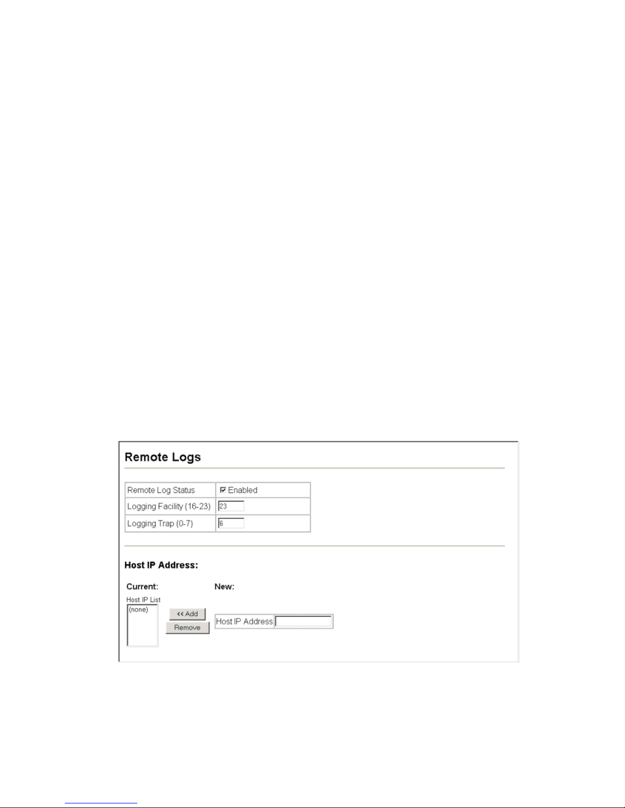
Basic Configuration
Remote Log Configuration
The Remote Logs page al lo ws you to configure th e l ogg in g of m essages that are
sent to syslog ser ve rs or ot her managemen t s tation s. You can also limit the error
messages sent to onl y t hose messages bel ow a specified level.
Command Attributes
• Remote Log Status – Enables/disables the logging of debug or err or me ssages
to the remote loggin g pr ocess. (Default: Enabled)
• Logging Facility – Sets the fac ilit y ty pe for re m ot e logging of syslog mes sag es.
There are eight facility types specified by values of 16 to 23. The facility type is
used by the syslog server to dispatch log messages to an appropriate service. The
attribute speci fies th e fa ci l ity type tag sent in syslog messages. (S ee R FC 3164.)
This type has no effect on the kind of messages reported by the switch. However,
it may be used by the syslog server to pro cess messages , s uch as sorting or
storing messages in the corresponding database. (Range: 16-23, Def ault: 23)
• Logging Trap – Limits log messages that are sent to the remote syslog server for
all levels up to the specified level. For example, if level 3 is specified, all messages
from level 0 to level 3 wi ll be s ent to the re m ot e ser ver. (Range: 0-7, Default: 7)
• Host IP List – Displays the list of remote serve r I P addresses that receive the
syslog messa ges. The maximum number of host IP addresses all ow ed is five.
• Host IP Address – Specifies a new ser ver IP address to add to the H ost I P Li st .
Web – Cl ick System, Log, Remote Logs. To add an IP address to the H ost IP Li st ,
type the new IP addre ss in the Host IP Addres s box, and then click Ad d. To delete
an IP address, click th e ent r y i n th e H ost IP List, and then cl ick R emove.
Figure 3-18. Remote Log s
3-29

Configuring the Switch
CLI – Enter the syslog s er ver hos t IP address, choose the facility type and s et the
logging trap.
Console(config)#logging host 192.168.1.15 4-45
Console(config)#logging facility 23 4-45
Console(config)#logging trap 4 4-46
Console(config)#end
Console#show logging trap 4-47
Syslog logging: Enabled
REMOTELOG status: Enabled
REMOTELOG facility type: local use 7
REMOTELOG level type: Warning conditions
REMOTELOG server ip address: 192.168.1.15
REMOTELOG server ip address: 0.0.0.0
REMOTELOG server ip address: 0.0.0.0
REMOTELOG server ip address: 0.0.0.0
REMOTELOG server ip address: 0.0.0.0
Console#
Simple Mail Transfer Protocol
SMTP (Simple Mail Transfer Protocol) is used to send email messages between
servers. The mes sa ges can be retrieved us ing PO P or IMAP clients.
Command Attributes
• Admin Status – Enable s/di sa bl es t he SMTP function. (Defau lt: Enabl ed)
• Email Source Address – This command specifies SMTP servers email addresses
that can send aler t messages.
• Severity – Specifies t he degree of urgenc y that th e m essage carries.
• Debugging – Sends a debugging not ificat i on. (Level 7)
• Information – Sends informatative not i fica t io n onl y . (Level 6)
• Notifice – Sends notification of a normal but significant condition, such as a cold
start. (Level 5)
• Warning – Sends not i fic at i on of a w ar ni ng condition such as retur n f al se, or
unexpected re tu rn . (Level 4)
• Error – Sends notification that an error conditions has occurred, such as invalid
input, or default used. (Level 3)
• Critical – Sends not i fica tion that a critical condi t ion has occurred, su ch as
memory allocat ion, or fr ee m emory error - resour ce exhausted. (Le vel 2)
• Alert – Sends urgent notification that imme di at e ac tion must be taken. (Le vel 1)
• Emergency – Sends an emergency notification that the system is now unusable.
(Level 0)
• SMTP Server List – Specifies a list of recipient SMTP servers.
• SMTP Server – Specifies a new SMTP server address to add to the SMTP Server
List.
• Email Destination Address List – Spe cifies a lis t of re ci pient Email Destinatio n
Address.
3-30

Basic Configuration
• Email Destination Address – This command sp ecifies SMTP servers th at ma y
receive alert me ssages.
Web – Click System, Log, SMTP. To add an IP address to the Server IP List, type
the new IP address in the Server IP Address box, and then click Add. To delete an IP
address, click th e ent r y in the Server IP List, and then click Remove .
Figure 3-19. Enabling and Configuring SMTP
CLI – Enter the host ip addr ess, followed by the m ai l se verity level, source and
destination ema il addresses and e nter the sendmail comm and to complete t he
action. Use the show l ogging command to dis play SMTP informat ion.
Console(config)#logging sendmail host 192.168.1.19
Console(config)#logging sendmail level 3
Console(config)#logging sendmail source-email
bill@this-company.com
Console(config)#logging sendmail destination-email
ted@this-company.com
Console(config)#logging sendmail
Console#
3-31

Configuring the Switch
Resetting the System
Web – Cl ick System, Reset. Cl ic k the R eset button to rebo ot th e sw i t ch. When
prompted, confirm that you want reset the switch.
Figure 3-20. Resetting the System
CLI – Use the reload command to restart the switch. W hen prompted, co nfi rm t hat
you want to reset the switch.
Console#reload 4-21
System will be restarted, continue <y/n>?
Note:
When restarting the system, it will always run the Power-On Self-Test.
Setting the System Clock
Simple Network Time Protocol (SNTP) allows the switch to set its internal clock
based on periodic upd at es from a time server (SN T P or NT P) . Maintaining an
accurate time on t he s w itc h enables the system lo g to rec or d m eaningful dates an d
times for event en tri es. You can also manually set th e cl ock using the CLI. (See
“calendar set” on page 4-56. ) If t he clock is not set, the switch will only reco rd th e
time from the factory default set at the last bootup.
When the SNTP clien t is en abled, the switch period ical ly sends a request for a time
update to a configur ed time server. You can configure up to three tim e server IP
addresses. The switch will attempt to poll each server in the configured sequence.
Configuring SNTP
You can configure the switch to send time synchronizatio n re quests to specific time
servers.
Command Attributes
• SNTP Client – Configures the sw itc h to oper at e as an SNT P clien t. This re qui r es
at least one time server to be specified in the SNTP Server field. (Default: Disabled)
• SNTP Poll Interval – Sets the interval between sending requests for a time update
from a time server. (Range: 16-16384 seconds; Default: 16 seconds )
• SNTP Server – Sets the IP address for up to three time servers. The switch
attempts to update the time from the first server, if this fails it attempts an update
from the next serv er in the sequence.
3-32

Basic Configuration
Web – Select SNTP, Conf igur ati on. M odif y any of th e requ ired pa ramet er s, and clic k
Apply.
Figure 3-21. S NTP C onfiguration
CLI – This example con figu re s t he switch to operate a s an SNTP unicast client an d
then displays the current time and set t in gs.
Console(config)#sntp client 4-54
Console(config)#sntp poll 60 4-55
Console(config)#sntp server 10.1.0.19 137.82.140.80 128.250.36.2 4-54
Console(config)#exit
Console#show sntp
Current time: Jan 6 14:56:05 2004
Poll interval: 60
Current mode: unicast
SNTP status : Enabled
SNTP server 10.1.0.19 137.82.140.80 128.250.36.2
Current server: 128.250.36.2
Console#
Setting the Time Zone
SNTP uses Coordinated Universal Time (or UTC, formerly Greenwich Mean Time,
or GMT) based on the time at the Earth’s prime meridian, zero degrees longitude. To
display a time cor re sponding to your loc al tim e, you must indicate the num ber of
hours and minut es y our time zone is east (b ef or e) or west (after) of UTC.
Command Attributes
• Current Time – Displays the current time.
• Name – Assigns a nam e t o th e t ime zone. (Range : 1-29 characters)
• Hours (0-13) – The num ber of hours before /a fter UTC.
• Minutes (0-59) – The number of minutes before/after UTC.
• Direction – Configures the tim e zone to be before (east ) or afte r ( west) UTC.
3-33

Configuring the Switch
Web – Select SNTP, Clock Time Zone. Set the offset for your time zone relative to
the UTC, and click Ap pl y.
Figure 3-22. Setting the Time Zone
CLI - This example shows how to set the time zone for the system clock.
Console(config)#clock timezone Dhaka hours 6 minute 0 after-UTC 4-56
Console#
Simple Network Management Protocol
Simple Network Management Pr otocol (SNM P ) is a communic ation protocol
designed specif i call y f or ma naging devices on a network. Equipment commonly
managed with S NM P in cludes switches, rout ers and host comp ut er s. SNM P i s
typically used to configure these devices for proper operation in a network
environment, as well as to monitor them to evaluate performance or detect potential
problems.
Managed devices supporting SNM P contain software, which runs locally on the
device and is referred to as an agent. A defined set of variables, known as managed
objects, is maintained by the SNMP agent and u sed to manage the devi ce. These
objects are defined in a M anagement Infor m at io n Bas e (M I B) th at pro vi de s a
standard presentation of the information controlled by the agent. SNMP defines both
the format of the MIB specifications and the protocol used to access this information
over the network.
The switch includes an onboard agent tha t s upp or ts SNM P ve rs io ns 1, 2c, and 3
clients. This agent conti nuously monitors t he sta tu s of th e sw i tch hardware, as we ll
as the traffic passing throug h its por ts. A network managem ent station can access
this information using software such as SMC EliteView. Access to the onboard agent
from clients using SNM P v1 and v2c is contro lle d by community stri ngs . To
communicat e w ith the sw i tch, th e m anagement station m us t firs t su bm i t a val id
community str in g fo r au t hentication.
Access to the switch using from clients usin g SNM P v3 provides addit ional security
features that cover message integ rit y, authentication, and encryption; as well as
controlling user access to specific areas of the MIB tree.
3-34

Simple Network Management Protocol
The SNMPv3 security structure consists of security models, with each model having
it’s own security levels. There are three security models defined, SNMPv1,
SNMPv2c, and SNMPv3. Users are ass igned to “groups” that are defined by a
security model and specified security levels. Each group also has a defined security
access to set of MIB objects for reading and writing, which are k now n as “views.”
The switch has a de fa ult vie w (a ll M IB obj ects) and default groups defi ned for
security mode ls v1 an d v2c. The following table shows the secu rit y m odels and
levels available and the system default settings.
Table 3-4 SNMPv3 Security Models and Levels
Model Level Group Read View Write View Notify
View
v1 noAuth
NoPriv
v1 noAuth
NoPriv
v1 noAuth
NoPriv
v2c noAuth
NoPriv
v2c noAuth
NoPriv
v2c noAuth
NoPriv
v3 noAuth
NoPriv
v3 Auth
NoPriv
public
(read
only)
private
(read/
write)
user
defined
public
(read
only)
private
(read/
write)
user
defined
user
defined
user
defined
defaultview none none Comm un ity strin g only
defaultview defau ltview none Comm un ity strin g only
user defined user defined user
defined
defaultview none none Comm un ity strin g only
defaultview defau ltview none Comm un ity strin g only
user defined user defined user
defined
user defined user defined user
defined
user defined user defined user
defined
Security
Community string only
Community string only
A user name match only
Provides user
authentication via MD5 or
SHA algorithms
v3 Auth Priv user
defined
Note:
The predefined default groups and view can be deleted from the system. You can
then define customized groups and views for the SNMP clients that require access.
user defined user defined user
defined
Provides user
authentication via MD5 or
SHA algorithms and data
privacy using DES 56-bit
encryption
3-35

Configuring the Switch
Enabling the SNMP Agent
Enables SNMPv3 service for all management clients (i.e., versions 1, 2c, 3).
Command Attributes
• SNMP Agent Status – Enables SNMP on the switch.
Web – Clic k SN M P, Agent Status. Enable the SNMP Agent by marking the Enabled
checkbox, and click Apply.
Figure 3-23. Enabling the SNMP Agent
CLI – The following exa m ple enables SNMP on th e swi t ch.
Console(config)#snmp-server 4-96
Console(config)#
Setting Community Access Strings
You may configure up to five com m unity strings autho rized for managem en t ac cess
by clients using SNMP v1 and v2c. All community strings used for IP Trap Managers
should be listed in this table. For security reasons, you should consider removing the
default strings.
Command Attributes
• SNMP Community Capabil ity – The switch supports up to five community strings.
• Current – Displays a list of the community strings c urrently configured.
• Community String – A com m unity stri ng that acts like a pass w ord and permits
access to the SNMP pr ot ocol.
• Default strin gs: “public” (r ead-only access), “priva te ” (read/write access)
• Range: 1-32 characters, case sensitive
• Access Mode – Specifies the access rights for the community string:
• Read-Only – Authorized management stations are only able to retrieve MIB
objects.
• Read/Write – Authorized manage m ent st at ions are able to both retr ie ve and
modify MIB objects.
3-36

Simple Network Management Protocol
Web – Cl ick SN M P, Configuratio n. Add new community st rings as required, sel e ct
the access right s from the Ac cess Mode drop-down li st, then cl i ck Add.
Figure 3-24. Configuring SNMP Commun ity String s
CLI – The following exa m pl e adds the string “sp ider man” with read/writ e access.
Console(config)#snmp-server community spiderman rw 4-98
Console(config)#
Specifying Trap Managers and Trap Types
Traps indicating status changes are issued by the switch to specified trap managers.
You must specify trap managers so that ke y events are reported by t his switch to
your management station (using netw or k m anagement platform s such as SMC
EliteView). You can specify up to five management stations that will receive
authentication failur e messages an d other notificati on messages from the switch.
Command Usage
• If you specify an SNMP Version 3 host, then the “Trap Manager Community String”
is interpreted as an SNM P user name. If you use V3 authentication or enc ry pt i on
options (authNo Pr iv or au t hPr iv ), t he us er nam e must first be define d in th e
SNMPv3 Users page (page 3-41). Otherwise, the authentication password and/or
privacy password will not exi st, and the switc h will no t authorize SNMP access for
the host. Howev er , if you specify a V3 host with th e no authentication (n oAuth)
option, an SNMP user account will be automatically generated, and the switch will
authorize SNMP ac cess for the host.
• Notifications are iss ue d by t he switch as trap mes sages by default. Th e re ci pi en t
of a trap message does not send a response to the switch. Traps are therefore not
as reliable as inform m essages, whi ch include a request for acknowledgement of
receipt. Informs can be used to ensure that critical information is received by the
host. However, note that informs co nsume more system resources be cau se t hey
must be kept in memory until a response is received. Informs also add to network
traffic. You shou ld consider these effect s w hen deciding whet her to issue
notifications as traps or informs.
• To send an inform to a SNM Pv2c host, com pl et e these steps:
3-37

Configuring the Switch
1. Enable the SNMP agent (page 3-36).
2. Enable trap informs as described in the fo llo w ing pages.
3. Create a view with the required notificat io n m essages (page 3-48).
4. Create a group that in cludes the required notify view (page 3-45).
• To send an inform to a SNM Pv3 host, comp le te th ese steps:
1. Enable the SNMP agent (page 3-36).
2. Enable trap informs as described in the fo llo w ing pages.
3. Create a view with the required notificat io n m essages (page 3-48).
4. Create a group that in cludes the required notify view (page 3-45).
5. Specify a remote engine ID where the user resides (page 3-40).
6. Then configure a r em ot e us er (page 3-43) .
Command Attributes
• Trap Manager Capability – This swi t ch supports up to five tr ap managers.
• Current – Displays a list of the trap m anagers currently configured.
• Trap Manager IP Address – IP address of a new management station to receive
notification mes sa ges.
• Trap Manager Community String – Specifies a valid com m unity string for the
new trap manager entry. Though you can set this string in the Trap Managers table,
we recommen d th at you define this string in the SN M P Configuration page (for
Version 1 or 2c clients ), or d ef ine a corresponding “User Name” in the SNM P v3
Users page (for Ver sion 3 clients). (Range: 1- 32 characters, case sensitive)
• Trap UDP Port – Specifies the UDP po rt number used by the trap manager.
• Trap Version – Indicates if the user is running SNMP v1, v2c , o r v3 . (D ef ault: v1)
• Trap Security Level – When trap version 3 i s selected, you must speci fy one of
the following secu ri ty l evels. (Default: noAuthNoPriv)
• noAuthNoPriv – There is no aut hentication or en cr yption used in SNMP
communications.
• AuthNoPriv – SNMP comm unications use authentication, but the data is not
encrypted (onl y available for the SN M P v3 security model).
• AuthPriv – SNMP communications use both authentication and encryption (only
available for the SNMPv3 security model).
• Trap Inform – Notifications are sent as inform messages. Note that this option is
only available f or version 2c and 3 hosts. (Default: traps are used)
• Timeout – The number of seconds to wait for an ac knowledgment be fo re
resending an infor m message. (Ran ge: 0- 2147483647 cent i se conds;
Default: 1500 centisec onds)
• Retry times – The maximum numb er of ti m es t o re send an inform mes sage if
3-38

Simple Network Management Protocol
the recipient does not acknowledge re ceipt. (Range: 0-255; D ef ault: 3)
1
• Enable Authentica tion Traps
trap managers whenever authenti cation of an SNMP request fails.
(Default: Enabled)
• Enable Link-up and Link-down Traps – Issues a notification message whenever
a port link is established or broken. (Default : Enabled)
Web – Cl ick SN M P, Configuration. E nt er the IP address and comm unity string for
each management station that will receive trap messages, specify the UDP port,
trap version, trap security level (f or v3 clients), trap in f or m set tin gs (for v2c/v3
clients), and then click Add. Select the trap types required using the check boxes for
Authentication and L in k- up/ down traps, and then clic k Apply.
– Issues a notification message to speci f i ed IP
Figure 3-25. Configuring S NM P Trap Manag ers
CLI – This example add s a trap manager and enables authentic at io n traps.
Console(config)#snmp-server host 10.1.19.23 inform private version 2c
udp-port 160 4-100
Console(config)#snmp-server enable traps authentication 4-102
Console(config)#
Configuring SNMPv3 Management Access
To configure SNMP v3 management access t o t he switch, f ollow thes e steps:
1. If you want to chang e th e default engine ID, it m ust be changed first bef ore
configuring othe r para m et er s.
2. Specify read and write access views for the switch M IB tree.
3. Configure SNMP user groups with the required security model (i.e., SNMP v1,
v2c or v3) and securit y level (i.e., authe ntication and priv acy).
1.
These are legacy notifications and therefore when used for SNMP Version 3 hosts, they
must be enabled in conjunction with the corresponding entries in the Notification View
(page 3-45).
3-39

Configuring the Switch
4. Assign SNMP use rs to groups, along with their speci f ic aut hentication and
privacy password s.
Setting the Local Engine ID
An SNMPv3 engine is an independent SNMP agent that resides on the switch. This
engine protects agai nst m es sage replay, delay, and redirection. The engine I D is
also used in comb in at io n w ith user passwords to ge ner at e the security keys for
authenticating and encry pting SNMPv3 packets.
A local engine ID is automatically generat ed that is unique to the sw itc h. T his i s
referred to as the de fa ul t e ngine ID. If the local engine ID is deleted or cha nged, all
SNMP users will be cleared. You will need to reconfigure all existing users.
A new engine ID can be specified by entering 1 to 26 hexadecimal characters. If less
than 26 character s ar e specified, trailing zer oes are added to the va l ue. For
example, the valu e “ 1234” is equivalent to “12 34” followed by 22 zer oes.
Web – Click SNMP, SNMPv3, Engine ID. Enter an ID of up to 26 hexadecimal
characters and t hen click Save.
Figure 3-26. Setting an Engine ID
CLI – This example sets an SNM Pv3 engine ID.
Console(config)#snmp-server engine-id local 12345abcdef 4-103
Console(config)#exit
Console#show snmp engine-id 4-104
Local SNMP engineID: 12345abcdef000000000000000
Local SNMP engineBoots: 1
Console#
Specifying a Remote Engine ID
To send inform mes sa ges to an SNMPv3 us er o n a re m ot e device, you must first
specify the engine identifier for the SN M P age n t on t he r emote device wher e t he
user resides. The remote engine ID is used to compute the security digest for
authenticating and encrypting pac kets sent to a user on th e re m ot e host.
SNMP passwords are localized using the engine ID of the authoritative agent. For
informs, the autho ritative SN M P agent is the remote agent. You therefore need to
configure the rem ot e ag ent’s SNMP engine ID befo re you can send proxy req uests
3-40

Simple Network Management Protocol
or informs to it. (See “Specifying Trap Managers and Trap Types” on page 3-37 and
“Configuring Remote SNMPv3 Users” on page 3-43.)
The engi ne ID can be spec i fied by entering 1 to 26 he xadecima l character s. If less
than 26 character s ar e specified, trailing zer oes are added to the va l ue. For
example, the valu e “ 1234” is equivalent to “12 34” followed by 22 zer oes.
Web – Click SNMP, SNMPv3, Remote Engine ID. Enter an ID of up to 26
hexadecima l ch ar acters and then cl ick Save.
Figure 3-27. Setting an Engine ID
CLI – This example spe cifie s a re mote SNMPv3 engi ne ID.
Console(config)#snmp-server engineID remote 54321 192.168.1.19 4-103
Console(config)#exit
Console#show snmp engine-id 4-104
Local SNMP engineID: 8000002a8000000000e8666672
Local SNMP engineBoots: 1
Remote SNMP engineID IP address
80000000030004e2b316c54321
192.168.1.19
Console#
Configuring SNMPv3 Users
Each SNMPv3 user is defined by a unique name. Users must be configured with a
specific security level and assigned to a group. The SNMPv3 group restricts users to
a specific read, wr ite, and notify view.
Command Attributes
• User Name – The name of user connecting to the SNMP agent. (Range: 1-32
characters)
• Group Name – The name of the SN M P group to which the user is assigned.
(Range: 1-32 chara cters)
• Security Model – The user sec ur ity model; SNMP v1, v2c or v3.
• Security Level – The security level used for the user:
• noAuthNoPriv – There is no authentication or encryption used in SNMP
communicat ions. (This is the default for SN M Pv3.)
• AuthNoPriv – SNMP communications use authenticatio n, but the data is not
encrypted (onl y available for the SN M P v3 security model).
3-41

Configuring the Switch
• AuthPriv – SNMP communications use both authentication and encryption (only
available for the SNMPv3 security model).
• Authentication Protocol – The metho d us ed f or user authentica tion.
(Options: MD5, SHA; Default: MD5)
• Authentication Password – A minimum of eight plain text characters is required.
• Privacy Protocol – The encryption algorithm use for data privacy; only 56-bit DES
is currently availa ble.
• Privacy Password – A minimum of ei ght plai n t ext characters is required.
• Actions – Enable s t he user to be assigned t o another SNMPv3 gr oup.
Web – Cl ick SN M P, SNMPv3, Users. Cl ick N ew to configure a user nam e . In t he
New User page, defin e a na me and assign it to a group, then click Add to save the
configuration and return to the User Name list. To delete a user, check the box next
to the user name, th en click Delete. To change the assi g ned group of a user, click
Change Group in t he Actions column of th e users table and select the new group.
Figure 3-28. Configuring SNMPv3 Users
3-42

Simple Network Management Protocol
CLI – Use the snmp-server user command to configure a new user name and
assign it to a group.
Console(config)#snmp-server user chris group r&d v3 auth md5 greenpeace
priv des56 einstien 4-109
Console(config)#exit
Console#show snmp user 4-110
EngineId: 80000034030001f488f5200000
User Name: chris
Authentication Protocol: md5
Privacy Protocol: des56
Storage Type: nonvolatile
Row Status: active
Console#
Configuring Remote SNMPv3 Users
Each SNMPv3 user is defined by a unique name. Users must be configured with a
specific security level and assigned to a group. The SNMPv3 group restricts users to
a specific read, wr ite, and notify view.
To send inform mes sa ges to an SNMPv3 us er o n a re m ot e device, you must first
specify the engine identifier for the SN M P age nt on t he r emote device wher e t he
user resides. The re m ot e engine ID is used to compute the security digest for
authenticating and encrypting pac kets sent to a user on th e re m ot e host. (See
“Specifying Trap Managers and Trap Ty pes” on page 3-37 and “Specifying a
Remote Engin e ID” on page 3-40.)
Command Attributes
• User Name – The name of user connecting to the SNMP agent. (Range: 1-32
characters)
• Group Name – The name of the SN M P group to which the user is assigned.
(Range: 1-32 chara cters)
• Engine ID – The engine identifier for the SNMP agent on the remote device where
the remote user res i des. Note that the remote engine identif i er must be specified
before you configur e a remote user. (Se e “Specifying a Remo te E ngine ID” on
page 3-40.)
• Remote IP – The Internet address of t he r emote device wher e t he user resides.
• Security Model – The user sec u r ity model; SNMP v1 , v2 c or v3. (D efault: v1)
• Security Level – The security level used for the user:
• noAuthNoPriv – There is no authentication or encryption used in SNMP
communicat ions. (This is the default for SN M Pv3.)
• AuthNoPriv – SNMP communications use authenticatio n, but the data is not
encrypted (onl y available for the SN M P v3 security model).
• AuthPriv – SNMP communications use both authentication and encryption (only
available for the SNMPv3 security model).
• Authentication Protocol – The metho d us ed f or user authentica tion. (Options:
MD5, SHA; Default: MD5)
3-43

Configuring the Switch
• Authentication Password – A minimum of eight plain text characters is required.
• Privacy Protocol – The encryption algorithm use for data privacy; only 56-bit DES
is currently availa ble.
• Privacy Password – A minimum of ei ght plai n t ext characters is required.
Web – Cl ick SN M P, SNMPv3, Remot e Us er s. Click New to configure a user name.
In the New User page, define a name and assign it to a group, then click Add to save
the configuration and return to the User N am e list. To delete a user, check the box
next to the user name, then click Delete.
Figure 3-29. Configuring Remote SNMP v3 Users
3-44

Simple Network Management Protocol
CLI – Use the snmp-server user command to configure a new user name and
assign it to a group.
Console(config)#snmp-server user mark group r&d remote 192.168.1.19 v3
auth md5 greenpeace priv des56 einstien 4-109
Console(config)#exit
Console#show snmp user 4-110
No user exist.
SNMP remote user
EngineId: 80000000030004e2b316c54321
User Name: mark
Authentication Protocol: none
Privacy Protocol: none
Storage Type: nonvolatile
Row Status: active
Console#
Configuring SNMPv3 Groups
An SNMPv3 group sets the access po licy fo r its ass ig ned users, restrict ing th em t o
specific read, writ e, and notify views. You can use the pre-defined defa ult g roups or
create new grou ps to map a set of SNMP users to SN M P vi ews.
Command Attributes
• Group Name – The name of the SN M P group. (Range: 1-3 2 ch ar act ers)
• Model – The grou p security model; SNM P v1, v2c or v3.
• Level – The security level used for the group:
• noAuthNoPriv – There is no authentication or encryption used in SNMP
communications.
• AuthNoPriv – SNMP communications use authenticatio n, but the data is not
encrypted (onl y available for the SN M P v3 security model).
• AuthPriv – SNMP communications use both authentication and encryption (only
available for the SNMPv3 security model).
• Read View – The configured view for read access. (Range: 1-64 char act ers)
• Write View – The configured view for write access. (Range: 1-64 characters)
• Notify View – The configured view for not ifi ca tions. (Range: 1-64 characters)
Table 3-5 Supported Notification Messages
Object Label Object ID Description
RFC 1493 Traps
newRoot 1.3.6.1.2.1.17.0.1 The newRoot trap indicates that the sending
agent has become the new root of the
Spanning Tree; the trap is sent by a bridge
soon after its election as the new root, e.g.,
upon expiration of the T opology Change Timer
immediately subsequent to its election.
3-45

Configuring the Switch
Table 3-5 Supported Notification Messages (Continued)
Object Label Object ID Description
topologyChange 1.3.6.1.2.1.17.0.2 A topologyChange trap is sent by a bridge
when any of its configured ports transitions
from the Learning state to the Forwarding
state, or from the Forwarding state to the
Discarding state. The trap is not sent if a
newRoot trap is sent for the same transition.
SNMPv2 Traps
coldStart 1.3.6.1.6.3.1.1.5.1 A coldStart trap signifies that the SNMPv2
entity, acting in an agent role, is reinitializing
itself and that its configuration may have been
altered.
warmStart 1.3.6.1.6.3.1.1.5.2 A warmStart trap signifies that the SNMPv2
entity, acting in an agent role, is reinitializing
itself such that its configuration is unaltered.
linkDown
linkUp
a
a
authenticationFailure
a
1.3.6.1.6.3.1.1.5.3 A linkDown trap signifies that the SNMP entity,
acting in an agent role, has detected that the
ifOperStatus object for one of its
communication links is about to enter the
down state from some other state (but not
from the notPresent state). This other state is
indicated by the included value of
ifOperStatus.
1.3.6.1.6.3.1.1.5.4 A linkUp trap signifies that the SNMP entity,
acting in an agent role, has detected that the
ifOperStatus object for one of its
communication links left the down state and
transit ione d int o so me ot her s tate (but not i nto
the notPresent state). This other state is
indicated by the included value of
ifOperStatus.
1.3.6.1.6.3.1.1.5.5 An authenticationFailure trap signifies that the
SNMPv2 entity, acting in an agent role, has
received a protocol message that is not
properly authenticated. While all
implementations of the SNMPv2 must be
capable of generating this trap, the
snmpEnableAuthenTraps object indicates
whether this trap will be generated.
RMON Events (V2)
risingAlarm 1.3.6.1.2.1.16.0.1 The SNMP trap that is generated when an
fallingAlarm 1.3.6.1.2.1.16.0.2 The SNMP trap that is generated when an
3-46
alarm entry crosses its rising threshold and
generates an event that is configured for
sending SNMP traps.
alarm entry crosses its falling threshold and
generates an event that is configured for
sending SNMP traps.

Simple Network Management Protocol
Table 3-5 Supported Notification Messages (Continued)
Object Label Object ID Description
Private Traps
swPowerStatus
ChangeTrap
swIpFilterRejectTrap 1.3.6.1.4.1.259.6.10.94.2.1.
a. These are legacy notifications and therefore must be enabled in conjunction with the
corresponding traps on the SNMP Configuration menu (page 3-39).
1.3.6.1.4.1.259.6.10.94.2.1.
0.1
0.40
This trap is sent when the power state
changes.
This trap is sent when an incorrect IP address
is rejected by the IP Filter.
Web – Click SNMP, SNMPv3, Groups. Click New to configure a new group. In the
New Group page, define a name, assign a security model and level, and then select
read and write views. Click Add to save the new group and return to the Groups list.
To delete a group, check the box next to th e gr oup name, then click D el et e.
Figure 3-30. Configuring SNMPv3 Groups
3-47

Configuring the Switch
CLI – Use the snmp-server group command to configure a new gr oup, specifying
the security mode l a nd l evel, and restricting MIB access to defined read and write
views.
Console(config)#snmp-server group secure-users v3 priv read defaultview
write defaultview notify defaultview 4-106
Console(config)#exit
Console#show snmp group 4-107
Group Name: secure-users
Security Model: v3
Read View: defaultview
Write View: defaultview
Notify View: defaultview
Storage Type: nonvolatile
Row Status: active
Console#
Setting SNMPv3 Views
SNMPv3 views are used to restrict user access to specified portions of the MIB tree.
The predefined view “defaultview” inc l ude s access to the entir e M IB tree.
Command Attributes
• View Name – The name of the SNM P view. (Range: 1-64 characters)
• View OID Subtrees – Shows the currently configured object identifiers of branches
within the MIB tree that define the SNMP view.
• Edit OID Subtrees – Allows you to conf ig ur e th e object identifiers of br an ches
within the MIB tree. Wild cards can be used to mask a speci fic portion of the OID
string.
• Type – Indicates if the object identifier of a br anch within the MIB tree is in cl uded
or excluded from the SNMP view.
Web – Click SNMP , SNMPv3, V ie ws. Click New to configure a new view. In the New
View page, define a name and specify OID subtrees in the switch MIB to be included
or excluded in the vi ew. Click Back to save t he new view and return to the S NM P v3
Views list. For a specific view, click on View OID S ubtrees to display the current
configuration, or click on Edit OID Subtrees to make changes to the view settings. T o
delete a view, check the box next to the view name, then click Delete.
3-48

Simple Network Management Protocol
Figure 3-31. Configuring SNMPv3 Views
CLI – Use the snmp-server view command to configure a new vi ew. This example
view includes the MIB-2 interfaces table, and the wildcard mask selects all index
entries.
Console(config)#snmp-server view ifEntry.a
1.3.6.1.2.1.2.2.1.1.* included 4-105
Console(config)#exit
Console#show snmp view 4-105
View Name: ifEntry.a
Subtree OID: 1.3.6.1.2.1.2.2.1.1.*
View Type: included
Storage Type: nonvolatile
Row Status: active
View Name: readaccess
Subtree OID: 1.3.6.1.2
View Type: included
Storage Type: nonvolatile
Row Status: active
View Name: defaultview
Subtree OID: 1
View Type: included
Storage Type: nonvolatile
Row Status: active
Console#
3-49

Configuring the Switch
User Authentication
You can restrict management access to this switch using the following options:
• User Accounts – Manually configure access rights on the switch for specified
users.
• Authentication Settings – Use remote authentication to configure access rights.
• HTTPS Settings – Provide a sec ur e w eb connection.
• SSH Settings – Provide a secu re shell (for secure Telnet access).
• Port Security – Configure s ecure addresses fo r individual ports.
• 802.1X – Use IEEE 802.1X port authenti cat ion to control access to s pecific ports.
• ACL - Access Control Lists (ACL) provide packet filtering for IP frames (based on
address, protocol, Layer 4 protocol port number or TCP control code) or any
frames (based on MAC address or Ethe rn et typ e) .
• IP Filter – Filters management ac cess to the web, SNMP or Te lnet in te rfac e.
Configuring User Accounts
The guest only has re ad access for mos t co nf i gur at ion parameters. Howe ver, the
administrator has w rit e access for all parameters governing the onboa rd agent. You
should therefo re assi gn a new administr at or passw or d as soon as possib le, and
store it in a safe place .
The default guest name is “guest” with the passw or d “ guest.” The default
administrator name is “admin” with the password “admin.”
Command Attributes
• Account List – Displays the current list of user accounts and associated access
levels. (Default: adm i n, an d guest)
• New Account – Displ ays configuration settings for a new ac count.
• User Name – The name of the user.
• (Maximum leng t h: 8 characters; maxim um number of users: 16 )
• Access Level – Specifies the user level.
(Options: Normal and Privileged)
• Password – Specifies the user password .
(Range: 0-8 characters plain text, case sensitive)
• Confirm Password – Re-enter th e user password.
• Change Password – Set s a new password for th e specified user nam e .
• Add/Remove – Adds or rem oves an account from the list.
3-50

User Authentication
Web – Cl ick Security, User Accounts. To conf i gure a new user account, specify a
user name, sele ct th e user’s acces s le vel, then enter a passwor d an d confirm it.
Click Add to save the new user account and add it to the Account List. T o change the
password for a spec ific user, enter the user name and new pass w or d, confirm the
password by entering it again, then click Apply.
Figure 3-32. Access Levels
CLI – Assign a user name to access-lev el 15 (i. e. , a dm ini st r at or ), th en sp ecify the
password.
Console(config)#username bob access-level 15 4-25
Console(config)#username bob password 0 smith
Console(config)#
Configuring Local/Remote Logon Authentication
Use the Authentication Settings menu to restrict management access based on
specified user names and passwords. You can manually configure access rights on
the sw itc h, o r y ou c a n use a re mot e acce s s au th en ti ca ti on se r ver ba se d on R AD IUS
or T ACACS+ protocols.
Web
Telnet
console
RADIUS/
TACACS+
server
1. Client attempts management access.
2. Switch contacts authentication server.
3. Authentication server challenges client.
4. Client responds with proper password or key.
5. Authentication server approves access.
6. Switch grants management access.
3-51

Configuring the Switch
Remote Authentication Dial-in User Service (RADIUS) and Terminal Access
Controller Access Control System Plus (T ACACS+) are logon authentication
protocols that use softw ar e running on a centra l ser ver to control acce ss t o
RADIUS-aware or TACACS -aware devices on the network. An authentication
server contains a da tabase of m ul tiple user name/password pairs with associ at ed
privilege levels for each user that requires management access to the switch.
RADIUS uses UDP while TACACS+ uses TCP. UDP only offers best effort delivery,
while TCP offers a connect i on- or i ent ed tr an sport. Also, note that R AD I US e ncrypts
only the password in the access-request packet from the client to the server, while
TACACS+ encrypt s t he entire bo dy of the pa cket.
Command Usage
• By default, management access is always checked against the auth ent i cation
database stored on the local switch. If a remote authentication server is used, you
must specify the aut hentication seque nce and the corresp onding parameter s f or
the remote authentication protocol. Local and remote logon authentication control
management access via the consol e port, web browser , or Te ln et.
• RADIUS and TACAC S+ logon authentic atio n as si gn a specific privilege le vel f or
each user name /p ass w or d pair. The user name , password, and privilege level
must be configured on t he authentication server.
• You can specify up t o th ree authentication methods for any user to indicate the
authentication sequence. For example, if you select (1) RADIUS, (2) TACACS and
(3) Local, the user name and password on the RADIUS server is verified first. If the
RADIUS server is not ava ilable, then authenti cation is attempted using the
TACACS+ server , and f inal l y the l ocal user name and pas sw or d is checked.
Command Attributes
• Authentication – Select the authentication, or authentication sequence required:
• Local – User authentication is performed only locally by the switch.
• Radius – User authentica tion is performed us ing a R AD I U S server only.
• TACACS – User authenti ca tion is performed usin g a TACACS+ server only.
• [authentication sequence ] – U s er aut hentication is perfor m ed by up to three
authentication me t hods in the indicated sequence.
• RADIUS Settings
• Global – Provides globall y ap pl i cab le R AD I US se tti ngs.
• ServerIndex – Specifies on e of five RADIUS serv er s th at m ay be configured.
The switch attempt s aut hentication using the l i sted sequence of servers. The
process ends when a server eithe r ap pr oves or denies acce ss t o a user.
• Server Port Number – Network (UDP) por t o f au th entication server us ed for
authentication messages.
(Range: 1-65535; Default: 1812)
• Secret Text String – Encryption key used to au th enti cate logon access fo r
client. Do not use blank spaces in the st ring.
(Maximum length: 20 characters)
3-52

User Authentication
• Number of Server Transmits – Number of times the switch tries to authenticate
logon access via t he authentication server. (Range: 1- 30; D ef au lt: 2)
• Timeout for a reply – The number of seconds the switch waits for a reply from
the RADIUS ser ver bef or e i t res ends the request. (Range: 1-65535; D ef ault : 5)
• TACACS Settings
• Server IP Address – Address of the TACACS+ server.
(Default: 10.11.12.13)
• Server Port Number – Network (TCP) por t of TA CA C S+ server used for
authentication messages.
(Range: 1-65535; Default: 49)
• Secret Text String – Encryption key used to au th enti cate logon access fo r
client. Do not use blank spaces in the st ring.
(Maximum length: 20 characters)
Note:
The local switch user database has to be set up by manually entering user names
and passwords using the CLI.
(See “username” on page 4-25.)
Web – Click Security, Authentication Settings. To configure local or remote
authentication pre fe rences, specify t he authentication sequence (i.e., on e t o th re e
methods), fill in the parameters for RADIUS or TACACS+ authentication if selected,
and click Apply.
Figure 3-33. Au thentication Settin g s
3-53

Configuring the Switch
CLI – Specify all the required parameters to en abl e logon authentic at io n.
Console(config)#authentication login radius 4-70
Console(config)#radius-server host 192.168.1.25 4-72
Console(config)#radius-server port 181 4-73
Console(config)#radius-server key green 4-74
Console(config)#radius-server retransmit 5 4-74
Console(config)#radius-server timeout 10 4-75
Console#show radius-server 4-75
Server IP address: 192.168.1.25
Communication key with radius server:
Server port number: 181
Retransmit times: 5
Request timeout: 10
Console(config)#authentication login tacacs 4-70
Console(config)#tacacs-server host 10.20.30.40 4-76
Console(config)#tacacs-server port 200 4-76
Console(config)#tacacs-server key green 4-77
Console#show tacacs-server 4-77
Server IP address: 10.20.30.40
Communication key with tacacs server: green
Server port number: 200
Console(config)#
Configuring HTTPS
You can configure the sw itch to enable the Secur e H yp er te xt Transfer Protocol
(HTTPS) over the Secure Socket Layer (SSL), providing secure access (i.e ., an
encrypted connection) to the switch’s web interface.
Command Usage
• Both the HTTP and HTTPS service can be en abl ed independently on th e swi t ch.
However, you cannot configure both services to use th e sam e UDP port.
• If you enable HTTPS, you must indicate this in the URL that you specify in your
browser: https://device[:port_number]
• When you start HTTPS, the connection is established in this way:
• The client authent i cates the server using t he server’s digital cert ifi cate.
• The client and ser ve r negotiate a set of security protocols to use for the
connection.
• The client and server generate session keys for encrypting and decrypting data.
• The client and server establish a secure encrypted connection.
• A padlock icon sh ou ld appear in the status bar for In te rnet Explorer 5.x or above
and Netscape Navigator 6.2 or above.
• The following web bro w sers and operating sy st em s currently support HTTPS:
3-54

User Authentication
Table 3-6 HTTPS Support
Web Browser Operating System
Internet Explorer 5.0 or later Windows 98,Windows NT (with service pack 6a),
Windows 2000, Windows XP
Netscape Navigator 6.2 or later Windows 98,Windows NT (with service pack 6a),
Windows 2000, Windows XP, Solaris 2.6
• To specify a secure -s ite cer tif icat e, see “Replacing the Default Secure-site
Certificate” on page 3-56.
Command Attributes
• HTTPS Status – Allows you to enable/disable the HT TPS server feature on the
switch.
•
Change HTTPS Port Number – Specifies the UDP port number used for HTTPS/
SSL connection to the sw itc h’s web interface. (Default : Po rt 443)
•
TFTP Server IP Address – Specifies the TF TP Server wh ere the authorized
certificate will be saved.
•
Source Certificate Fi le Na m e – Fi le name for the certificat e.
(Default: Enabled)
•
Source Private File Name – Private ke y file name.
•
Private Password – Pa ssword for the private key.
Web – Click Security, HTTPS Settings. Enable HTTPS and specify the port number,
then click Apply. To replace the default secure-site certificate, enter the TFTP Server
IP Address, the Source Certificate File Name, the Source Private File Name, and the
Private Password, then click Copy Certificate.
Figure 3-34. HTTPS Settings
3-55
 Loading...