

Page 1

SMC8124PL2
TM
TigerSwitch 10/100/1000
24-Port Managed Switch with PoE
INSTALLATION GUIDE
Installationsanleitung
Page 2

Page 3

TigerSwitch 10/100/1000
Installation Guide
From SMC’s Tiger line of feature-rich workgroup LAN solutions
20 Mason
Irvine, CA 92618
Phone: (949) 679-8000
May 2007
Pub. # 150200061500A
E052007-DT-R01
Page 4

Information furnished by SMC Networks, Inc. (SMC) is believed to be accurate and
reliable. However, no responsibility is assumed by SMC for its use, nor for any
infringements of patents or other rights of third parties which may result from its use. No
license is granted by implication or otherwise under any patent or patent rights of SMC.
SMC reserves the right to change specifications at any time without notice.
Copyright © 2007 by
SMC Networks, Inc.
20 Mason
Irvine, CA 92618
All rights reserved. Printed in T aiwan
Trademarks:
SMC is a registered trademark; and EZ Switch, TigerStack and TigerSwitch are
trademarks of SMC Networks, Inc. Other product and company names are trademarks or
registered trademarks of their respective holders.
Page 5

Limited Warranty
Limited Warranty Statement: SMC Networks, Inc. (“SMC”) warrants its products to be
free from defects in workmanship and materials, under normal use and service, for the
applicable warranty term. All SMC products carry a standard 90-day limited warranty from
the date of purchase from SMC or its Authorized Reseller. SMC may , at i ts own discretion,
repair or replace any product not operating as warranted with a similar or functionally
equivalent product, during the applicable warranty term. SMC will endeavor to repair or
replace any product returned under warranty within 30 days of receipt of the product.
The standard limited warranty can be upgraded to a Limited Lifetime* warranty by
registering new products within 30 days of purchase from SMC or its Authorized Reseller.
Registration can be accomplished via the enclosed product registration card or online via
the SMC Web site. Failure to register will not affect the standard limited warranty. The
Limited Lifetime warranty covers a product during the Life of that Product, which is
defined as the period of time during which the product is an “Active” SMC product. A
product is considered to be “Active” while it is listed on the current SMC price list. As new
technologies emerge, older technologies become obsolete and SMC will, at its discretion,
replace an older product in its product line with one that incorporates these newer
technologies. At that point, the obsolete product is discontinued and is no longer an
“Active” SMC product. A list of discontinued products with their respective dates of
discontinuance can be found at:
http://www.smc.com/index.cfm?action=customer_service_warranty.
All products that are replaced become the property of SMC. Replacement products may
be either new or reconditioned. Any replaced or repaired product carries either a 30-day
limited warranty or the remainder of the initial warranty, whichever is longer. SMC is not
responsible for any custom software or firmware, configuration information, or memory
data of Customer contained in, stored on, or integrated with any products returned to
SMC pursuant to any warranty. Products returned to SMC should have any
customer-installed accessory or add-on components, such as expansion modules,
removed prior to returning the product for replacement. SMC is not responsible for these
items if they are returned with the product.
Customers must contact SMC for a Return Material Authorization number prior to
returning any product to SMC. Proof of purchase may be required. Any product returned
to SMC without a valid Return Material Authorization (RMA) number clearly marked on
the outside of the package will be returned to customer at customer’s expense. For
warranty claims within North America, please call our toll-free customer support number
at (800) 762-4968. Customers are responsible for all shipping charges from their facility to
SMC. SMC is responsible for return shipping charges from SMC to customer.
WARRANTIES EXCLUSIVE: IF AN SMC PRODUCT DO ES NOT OPERATE AS
WARRANTED ABOVE, CUSTOMER’S SOLE REMEDY SHALL BE REPAIR OR
REPLACEMENT OF THE PRODUCT IN QUESTION, AT SMC’S OPTION. THE
FOREGOING WARRANTIES AND REMEDIES ARE EXCLUSIVE AND ARE IN LIEU OF
ALL OTHER WARRANTIE S O R CO NDITIONS , EX PR E SS O R IM PLIED, EITHER IN
FACT OR BY OPERATION OF LAW, STATUTORY OR OTHERWISE, INCLUDING
WARRANTIES OR CONDITIONS OF MERCHANTABILITY AND FITNESS FOR A
PARTICULAR PURPOSE. SMC NEITHER ASSUMES NOR AUTHORIZES ANY OTHER
PERSON TO ASSUME FOR IT ANY OTHER LIABILITY IN CONNECTION WITH THE
SALE, INSTALLATION, MAINTENANCE OR USE OF ITS PRODUCTS. SMC SHALL
v
Page 6

NOT BE LIABLE UNDER THIS WARRANTY IF ITS TESTING AND EXAMINATION
DISCLOSE THE ALLEGED DEFECT IN THE PRODUCT DOES NOT EXIST OR WAS
CAUSED BY CUSTOMER’S OR ANY THIRD PERSON’S MISUSE, NEGLECT,
IMPROPER INSTALLATION OR TESTING, UNAUTHORIZED ATTEMPTS TO REPAIR,
OR ANY OTHER CAUSE BEYOND THE RANGE OF THE INTENDED USE, OR BY
ACCIDENT, FIRE, LIGHTNING, OR OTHER HAZARD.
LIMITATION OF LIABILITY: IN NO EVENT, WHETHER BASED IN CONTRACT OR
TORT (INCLUDING NEGLIGENCE), SHALL SMC BE LIABLE FOR INCIDENTAL,
CONSEQUENTIAL, INDIRECT, SPECIAL, OR PUNITIVE DAMAGES OF ANY KIND, OR
FOR LOSS OF REVENUE, LOSS OF BUSINESS, OR OTHER FINANCIAL LOSS
ARISING OUT OF OR IN CONNECTION WITH THE SALE, INSTALLATION,
MAINTENANCE, USE, PERFORMANCE, FAILURE, OR INTERRUPTION OF ITS
PRODUCTS, EVEN IF SMC OR ITS AUTHORIZED RESELLER HAS BEEN ADVISED
OF THE POSSIBILITY OF SUCH DAMAGES.
SOME STATES DO NOT ALLOW THE EXCLUSION OF IMPLIED WARRANTIES OR
THE LIMITATION OF INCIDENTAL OR CONSEQUENTIAL DAMAGES FOR
CONSUMER PRODUCTS , SO THE ABOVE LIM ITATION S AN D EXCLUSION S MAY
NOT APPLY TO YOU. THIS WARRANTY GIVES YOU SPECIFIC LEGAL RIGHTS,
WHICH MAY VARY FROM STATE TO STATE. NOTHING IN THIS WARRANTY SHALL
BE TAKEN TO AFFECT YOUR STATUTO RY RIGHTS.
* SMC will provide warranty service for one year following discontinuance from the active
SMC price list. Under the limited lifetime warranty, internal and external power supplies,
fans, and cables are covered by a standard one-year warranty from date of purchase.
SMC Networks, Inc.
20 Mason
Irvine, CA 92618
vi
Page 7

Compliances and Safety Warnings
FCC - Class A
This equipment has been tested and found to comply with the limits for a Class A digital
device, pursuant to part 15 of the FCC Rules. These limits are designed to provide
reasonable protection against harmful interference when the equipment is operated in a
commercial environment. This equipment generates, uses, and can radiate radio
frequency energy and, if not installed and used in accordance with the instruction manual,
may cause harmful interference to radio communications. Operation of this equipment in
a residential area is likely to cause harmful interference in which case the user will be
required to correct the interference at his own expense.
You are cautioned that changes or modifications not expressly approved by the party
responsible for compliance could void your authority to operate the equipment.
You may use unshielded twisted-pair (UTP) for RJ-45 connections - Category 3 or better
for 10 Mbps connections, Category 5 or better for 100 Mbps connections, Category 5, 5e,
or 6 for 1000 Mbps connections. For fiber optic connections, you may use 50/125 or 62.5/
125 micron multimode fiber or 9/125 micron single-mode fiber.
Industry Canada - Class A
This digital apparatus does not exceed the Class A limits for radio noise emissions from
digital apparatus as set out in the interference-causing equipment standard entitled
“Digital Apparatus,” ICES-003 of the Department of Communications.
Cet appareil numérique respecte les limites de bruits radioélectriques applicables aux
appareils numériques de Classe A prescrites dans la norme sur le matériel brouilleur:
“Appareils Numériques,” NMB-003 édictée par le ministère des Communications.
Japan VCCI Class A
vii
Page 8

CE Mark Declaration of Conformance for EMI and Safety (EEC)
This information technology equipment complies with the requirements of the Council
Directive 89/336/EEC on the Approximation of the laws of the Member States relating to
Electromagnetic Compatibility and 73/23/EEC for electrical equipment used within certain
voltage limits and the Amendment Directive 93/68/EEC. For the evaluation of the
compliance with these Directives, the following standards were applied:
RFI Emission: Limit class A according to EN 55022:1998
Limit class A for harmonic current emission according to EN 61000-3-2/1995
Limitation of voltage fluctuation and flicker in low-voltage supply system according to
EN 61000-3-3/1995
Immunity: Product family standard according to EN 55024:1998
Electrostatic Discharge according to EN 61000-4-2:1995 (Contact Discharge: ±4 kV,
Air Discharge: ±8 kV)
Radio-frequency electromagnetic field according to EN 61000-4-3:1996 (80 - 1000
MHz with 1 kHz AM 80% Modulation: 3 V/m)
Electrical fast transient/burst according to EN 61000-4-4:1995 (AC/DC power supply:
±1 kV, Data/Signal lines: ±0.5 kV)
Surge immunity test according to EN 61000-4-5:1995
(AC/DC Line to Line: ±1 kV, AC/DC Line to Earth: ±2 kV)
Immunity to conducted disturbances, Induced by radio-frequency fields:
EN 61000-4-6 :19 96 (0.1 5 - 80 MHz with
1 kHz AM 80% Modulation: 3 V/m)
Power frequency magnetic field immunity test according to EN 61000-4-8:1993 (1 A/m
at frequency 50 Hz)
Voltage dips, short interruptions and voltage variations immunity test according to
EN 61000-4-11:1994 (>95% Reduction @10 ms, 30% Reduction @500 ms, >95%
Reduction @5000 ms)
LVD: EN 60950-1:2 001
Caution: Do not plug a phone jack connector in the RJ-45 port. This may damage this
device.
Attention:Les raccordeurs ne sont pas utilisés pour le système téléphonique!
viii
Page 9

Safety Compliance
Warning: Fiber Optic Port Safety
When using a fiber optic port, never look at the transmit laser while it is
CLASS I
LASER DEVICE
powered on. Al so, never look di rectly at the fi ber TX po rt and fiber cab le
ends when they are powered on.
Avertissment: Ports pour fibres optiques - sécurité sur le plan optique
Ne regardez jamais le laser tant qu'il est sous tension. Ne regardez
DISPOSITIF LASER
DE CLASSE I
jamais directement le port TX (Transmission) à fibres optiques et les
embouts de câbles à fibres optiques tant qu'ils son t s ous tension.
Warnhinweis: Faseroptikanschlüsse - Optische Sicherheit
LASERGER
DER KLASSE I
ÄT
Niemals ein Übertragungslaser betrachten, während dieses
eingeschaltet ist. Niemals direkt auf den Faser-TX-Anschluß
und auf die Faserkabelenden schauen, während diese
eingeschaltet sind.
Power Cord Safety
Please read the following safety information carefully before installing this switch:
Warning: Installation and removal of the unit must be carried out by qualified personnel
only.
• The unit must be connected to an earthed (grounded) outlet to comply with international
safety standards.
• Do not connect the unit to an A.C. outlet (power supply) without an earth (ground)
connection.
• The appliance coupler (the connector to the unit and not the wall plug) must have a
configuration for mating with an EN 60320/IEC 320 appliance inlet.
• The socket outlet must be near to the unit and easily accessible. You can only remove
power from the unit by disconnecting the power cord from the outlet.
• This unit operates under SELV (Safety Extra Low Voltage) conditions according to
IEC 60950. The conditions are only maintained if the equipment to which it is connected
also operates under SELV conditions.
France and Peru only
This unit cannot be powered from IT
†
supplies. If your supplies are of IT type, this unit
must be powered by 230 V (2P+T) via an isolation transformer ratio 1:1, with the
secondary connection point labelled Neutral, connected directly to earth (ground).
†
Impédance à la terre
ix
Page 10

Important! Before making connections, make sure you have the correct cord set. Check
it (read the label on the cable) against the following:
Power Cord Set
U.S.A. and Canada The cord set must be UL-approved and CSA certified.
The minimum specifications for the flexible cord are:
- No. 18 AWG - not longer than 2 meters, or 16 AWG.
- Type SV or SJ
- 3-conductor
The cord set must have a rated current capacity of at least 10 A
The attachment plug must be an earth-grounding type with NEMA 5-15P (15 A,
125 V) or NEMA 6-15P (15 A, 250 V) configuration.
Denmark The supply plug must comply with Section 107-2-D1, Standard DK2-1a or
DK2-5a.
Switzerland The supply plug must comply with SEV/ASE 1011.
U.K. The supply plug must comply with BS1363 (3-pin 13 A) and be fitted with a 5 A
fuse which complies with BS1362.
The mains cord must be <HAR> or <BASEC> marked and be of type
HO3VVF3GO. 75 (min imu m).
Europe The supply plug must comply with CEE7/7 (“SCHUKO”).
The mains cord must be <HAR> or <BASEC> marked and be of type
HO3VVF3GO. 75 (min imu m).
IEC-320 receptacle.
Veuillez lire à fond l'information de la sécurité suivante avant
d'installer le Switch:
AVERTISSEMENT: L’installation et la dépose de ce groupe doivent être confiés à un
personnel qualifié.
• Ne branchez pas votre appareil sur une prise secteur (alimentation électrique) lorsqu'il
n'y a pas de connexion de mise à la terre (mise à la masse).
• Vous devez raccorder ce groupe à une sortie mise à la terre (mise à la masse) afin de
respecter les normes internationales de sécurité.
• Le coupleur d’appareil (le connecteur du groupe et non pas la prise murale) doit
respecter une configuration qui permet un branchement sur une entrée d’appareil EN
60320/IEC 320.
• La prise secteur doit se trouver à proximité de l’appareil et son accès doit être facile.
Vous ne pouvez mettre l’appareil hors circuit qu’en débranchant son cordon électrique
au niveau de cette prise.
• L’appareil fonctionne à une tension extrêmement basse de sécurité qui est conforme à
la norme IEC 60950. Ces conditions ne sont maintenues que si l’équipement auquel il
est raccordé fonctionne dans les mêmes conditions.
France et Pérou uniquement:
x
Page 11

Ce groupe ne peut pas être alimenté par un dispositif à impédance à la terre. Si vos
alimentations sont du type impédance à la terre, ce groupe doit être alimenté par une
tension de 230 V (2 P+T) par le biais d’un transformateur d’isolement à rapport 1:1, avec
un point secondaire de connexion portant l’appellation Neutre et avec raccordement
direct à la terre (masse).
Cordon électrique - Il doit être agréé dans le pays d’utilisation
Etats-Unis et Canada: Le cordon doit avoir reçu l’homologation des UL et un certificat de la CSA.
Les spécifications minimales pour un cable flexible sont AWG No. 18, ouAWG
No. 16 pour un cable de longueur inférieure
- type SV ou SJ
- 3 conducteurs
Le cordon doit être en mesure d’acheminer un courant nominal d’au moins 10
A.
La prise femelle de branchement doit être du type à mise à la terre (mise à la
masse) et respecter la configuration NEMA 5-15P (15 A, 125 V) ou NEMA
6-15P (15 A, 250 V).
Danemark: La prise mâle d’alimentation doit respecter la section 107-2 D1 de la norme
DK2 1a ou DK2 5a.
à
2 métres.
Suisse: La prise mâle d’alimentation doit respecter la norme SEV/ASE 1011.
Europe La prise secteur doit être conforme aux normes CEE 7/7 (“SCHUKO”)
LE cordon secteur doit porter la mention <HAR> ou <BASEC> et doit être de
type HO3VVF3GO.75 (minimum).
Bitte unbedingt vor dem Einbauen des Switches die folgenden
Sicherheitsanweisungen durchlesen:
WARNUNG: Die Installation und der Ausbau des Geräts darf nur durch Fachpersonal
erfolgen.
• Das Gerät sollte nicht an eine ungeerdete Wechselstromsteckdose angeschlossen
werden.
• Das Gerät muß an eine geerdete Steckdose angeschlossen werden, welche die
internationalen Sicherheitsnormen erfüllt.
• Der Gerätestecker (der Anschluß an das Gerät, nicht der Wandsteckdosenstecker) muß
einen gemäß EN 60320/IEC 320 konfigurierten Geräteeingang haben.
• Die Netzsteckdose muß in der Nähe des Geräts und leicht zugänglich sein. Die
Stromversorgung des Geräts kann nur durch Herausziehen des Gerätenetzkabels aus
der Netzsteckdose unterbrochen werden.
• Der Betrieb dieses Geräts erfolgt unter den SELV-Bedingungen
(Sicherheitskleinstspannung) gemäß IEC 60950. Diese Bedingungen sind nur gegeben,
wenn auch die an das Gerät angeschlossenen Geräte unter SELV-Bedingungen
betrieben werden.
xi
Page 12

Stromkabel. Dies muss von dem Land, in dem es benutzt wird geprüft werden:
Schweiz Dieser Stromstecker muß die SEV/ASE 1011Bestimmungen einhalten.
Europe Das Netzkabel muß vom Typ HO3VVF3GO.75 (Mindestanforderung) sein und
die Aufschrift <HAR> oder <BASEC> tragen.
Der Netzstecker muß die Norm CEE 7/7 erfüllen (”SCHUKO”).
Warnings and Cautionary Messages
Warning: This product does not contain any serviceable user parts.
Warning: Installation and removal of the unit must be carried out by qualified
personnel only.
Warning: When connecting this device to a power outlet, connect the field
ground lead on the tri-pole power plug to a valid earth ground line to
prevent electrical hazards.
Warning: This switch uses lasers to transmit signals over fiber optic cable. The
lasers are compliant with the requirements of a Class 1 Laser
Product and are inherently eye safe in normal operation. However,
you should never look directly at a transmit port when it is powered
on.
Caution: Wear an anti-static wrist strap or take other suitable measures to
prevent electrostatic discharge when handling this equipment.
Caution: Do not plug a phone jack connector in the RJ-45 port. This may
damage this device. Les raccordeurs ne sont pas utilisé pour le
système téléphonique!
Caution: Use only twisted-pair cables with RJ-45 connectors that conform to
FCC standards.
Warnings (in German)
Achtung: Dieses Produkt enthält keine Teile, die eine Wartung vom Benutzer
benötigen.
Achtung: Installation und Deinstallation des Gerätes müssen von qualifiziertem
Servicepersonal durchgeführt werden.
Achtung: Wenn das Gerät an eine Steckdose angeschlossen wird, muß der
Masseanschluß am dreipoligen Netzstecker mit Sch utzerde
verbunden werden, um elektrische Gefahren zu vermeiden.
Achtung: Dieses Gerät nutzt Laser zur Signalübertragung über Glasfasern. Die
Laser entsprechen den Anforderungen an eine Lasereinrichtung der
Klasse 1 und sind durch ihre Bauart im normalen Betrieb sicher für die
Augen. Trotzdem sollte niemals direkt in den einen
Übertragungskanal geblickt werden, wenn er eingeschaltet ist.
xii
Page 13

Environmental Statement
The manufacturer of this product endeavours to sustain an environmentally-friendly policy
throughout the entire production process. This is achieved though the following means:
• Adherence to nation al le gi slat i on and regulations on environmental production
standards.
• Conservation of operational resources.
• Waste reduction and safe disposal of al l harmful un-recyc la bl e by -products.
• Recycling of all reusa ble w aste content.
• Design of products to m aximize recyclabl es at the end of the prod uc t’s l ife span.
• Continual monitori ng of safety standards.
End of Product Life Span
This product is manufactured in such a way as to allow for the recovery and disposal of all
included electrical components once the product has reached the end of its life.
Manufacturing Materials
There are no hazardous nor ozone-depleting materials in this product.
Documentation
All printed documentation for this product uses biodegradable paper that originates from
sustained and managed forests. The inks used in the printing process are non-toxic.
Purpose
This guide details the hardware features of this switch, including Its physical and
performance-related characteristics, and how to install the switch.
Audience
This guide is for system administrators with a working knowledge of network
management. You should be familiar with switching and networking concepts.
Zielgruppe Dieser Anleitung ist fuer Systemadministratoren mit Erfahrung im
Netzwerkmangement. Sie sollten mit Switch- und Netzwerkkonzepten vertraut sein.
Related Publications
The following publication gives specific information on how to operate and use the
management functions of this switch:
The SMC8124PL2 Management Guide
Also, as part of both switches firmware, there is an online web-based help that describes
all management related features.
xiii
Page 14

xiv
Page 15

Contents
Chapter 1: About the TigerSwitch 10/100/1000 1-1
Overview 1-1
Switch Architecture 1-1
Power-over-Ethernet Capability 1-2
Network Management Options 1-2
Description of Hardware 1-2
10/100/1000BASE-T Ports 1-2
SFP Slots 1-3
Port and System Status LEDs 1-3
Power Supply Socket 1-4
Features and Benefits 1-4
Connectivity 1-4
Expandability 1-5
Performance 1-5
Management 1-5
Chapter 2: Network Planning 2-1
Introduction to Switching 2-1
Application Examples 2-1
Collapsed Backbone 2-1
Network Aggregation Plan 2-2
Remote Connection s with Fib er Cab le 2-3
Making VLAN Connections 2-3
Application Notes 2-4
Chapter 3: Installing the Switch 3-1
Selecting a Site 3-1
Ethernet Cabling 3-1
Equipment Checkl is t 3-2
Package Contents 3-2
Optional Rack-Mounting Equipment 3-2
Mounting 3-3
Rack Mounting 3-3
Desktop or Shelf Mounting 3-4
Installing an SFP Transceiver 3-5
Connecting to a P ower Source 3-6
Connecting to the Console Port 3-6
Wiring Map for Serial Cable 3-7
xv
Page 16

Contents
Chapter 4: Making Network Connections 4-1
Connecting Network Devices 4-1
Twisted-Pair Devices 4-1
Power-over-Et hernet Connections 4-1
Cabling Guidelines 4-1
Connecting to PCs, Servers, Hubs and Switches 4-2
Network Wiring Connections 4-2
Fiber Optic SFP Devices 4-3
Connectivity Rules 4-5
1000BASE-T Cable Requirements 4-5
1000 Mbps Gigabit Ethernet Collision Domain 4-5
100 Mbps Fast Ethernet Collision Domain 4-6
10 Mbps Ethernet Collis ion Domai n 4-6
Cable Labeling and Connection Records 4-6
Appendix A: Troubleshooting A-1
Diagnosing Switch Indicators A-1
Power and Cooling Problems A-1
Installation A-1
In-Band Access A-2
Appendix B: Cables B-1
Twisted-Pair Cable and Pin Assignments B-1
10BASE-T/100BASE-TX Pin Assignments B-1
Straight-Through Wiring B-2
Crossover Wiring B-3
1000BASE-T Pin Assignments B-3
Cable Testing for Existing Category 5 Cable B-4
Adjusting Existing Category 5 Cabling to Run 1000BASE-T B-4
Fiber Standards B-4
Appendix C: Specifications C-1
Physical Characteristics C-1
Switch Features C-2
Management Features C-2
Standards C-2
Compliances C-3
Warranty C-3
xvi
Page 17

Contents
Appendix D: German Instructions D-1
Eine Site Auswählen (Selecting a Site) D-1
Montage (Rack Mounting Instructions) D-1
Rack-Montage D-1
Appendix E: Ordering Information E-1
Glossary
Index
xvii
Page 18

Contents
xviii
Page 19

Tables
Table 1-1 Port Status LEDs 1-3
Table 1-2 System Status LEDs 1-4
Table 3-1 Serial Cable Wiring 3-7
Table 4-1 Maximum 1000BASE-T Gigabit Ethernet Cable Length 4-5
Table 4-2 Maximum 1000BASE-SX Fiber Optic Cable Length 4-5
Table 4-3 Maximum 1000BASE-LX Fiber Optic Cable Length 4-6
Table 4-4 Maximum 1000BASE-ZX Fiber Optic Cable Length 4-6
Table 4-5 Maximum Fast Ethernet Cable Length 4-6
Table 4-6 Maximum Ethernet Cable Length 4-6
Table A-1 Troubleshooting Chart A-1
Table B-1 10/100BASE-TX MDI and MDI-X Port Pinouts B-2
Table B-2 1000BASE-T MDI and MDI-X Port Pinouts B-3
Table E-1 TigerSwitch 10/100/1000 Products and Accessories E-1
xix
Page 20

Figures
Figure 1-1 Front P anel 1-1
Figure 1-2 Rear Panel 1-1
Figure 1- 3 Port and System LEDs 1-3
Figure 1-4 Power Supply Sockets 1-4
Figure 2-1 Collapsed Backbone 2-2
Figure 2-2 Network Aggregation Plan 2-2
Figure 2-3 Remote Connections with Fiber Cable 2-3
Figure 2-4 Making VLAN Connections 2-4
Figure 3-1 RJ-45 Connections 3-2
Figure 3-2 Attaching the Brackets 3-3
Figure 3-3 Installing the Switch in a Rack 3-4
Figure 3-4 Attaching the Adhesive Feet 3-4
Figure 3-5 Inserting an SFP Transceiver into a Slot 3-5
Figure 3-6 Power Socket 3-6
Figure 3-7 Serial Port (DB-9 DTE) Pin-Out 3-6
Figure 4-1 Making Twisted-Pair Connections 4-2
Figure 4-2 Wiring Closet Connections 4-3
Figure 4-3 Making Connections to SFP Transceivers 4-4
Figure B-1 RJ-45 Connector Pin Numbers B-1
Figure B-2 Straight-through Wiring B-2
Figure B-3 Crossover Wiring B-3
xx
Page 21
Chapter 1: About the
TigerSwitch 10/100/1000
Overview
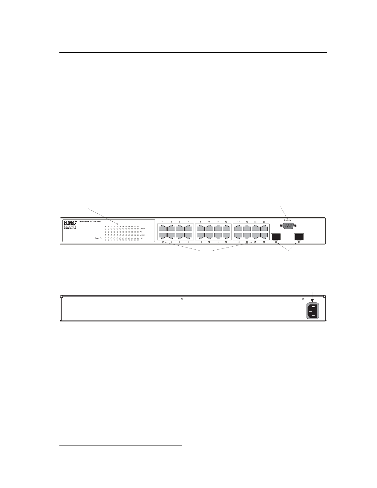
SMC’s TigerSwitch 10/100/1000 SMC8124PL2 is an intellig ent Layer 2 PoE switch
with 24 10/100/1000BASE-T ports, two of which are combination po rts
shared with two SFP transceiver slots (see Figure 1-1, Ports 23-24).
The switch includes an SNMP-base d m ana gement agent embedded on the main
board, which supports both in-band an d out - of -b and management access.
It can easily enhance your network w ith fu ll support for Spanning Tree Protocol,
multicast switching, and virtual LA N s. It br in gs order to poorly perfo rm ing networks
by segregating them into separate bro adc ast domains with IEEE 802.1Q compliant
VLANs, and empo w er s m ul t ime di a applications with mu lti cas t swi tc hing and CoS
services.
*
that are
Port Status LEDs
10/100/1000 Mbps RJ-45 Ports
Figure 1-1 Front Panel
Figure 1-2 Rear Panel
Console Port
SFP Slots
Power Socket
100-240V~
3A50-60Hz
Switch Architecture
This Gigabit Ethernet switch empl oys a wire-speed, non-blocking swit chi ng fa bric.
This permits simultaneous wire-speed transport of multiple packets at low latency on
all ports. The switch also features full-duplex capability on all ports, which effectively
doubles the bandw idth o f ea ch connection.
For communica tions within the sam e VLAN, the switch us es st o re-and-forward
switching to ensure maximum data integrity. The entire packet must be received into
* If an SFP transceiver is plugged in, the corresponding RJ-45 port is disabled for ports 23-24.
1-1
Page 22

1
About the TigerSwitch 10/100/1000
a buffer and checked for va l id ity b ef or e bei ng forwarded. Th is pre vents errors from
being propagated th ro ughout the network.
Power-over-Ethernet Capability
The switch’s 24 10/100/1000 Mbps ports support the IEEE 802.3af
Power-over-Eth er net (PoE) standard that ena bles DC power to be supplied to
attached devices us in g wi re s i n th e co nnecting Ethernet cab le . An y 802.3af
compliant device attached to a port can directly draw power from the switch over the
Ethernet cable without requiring its own separate power source. This capability gives
network administrators centralized power control for devices such as IP phones and
wireless access points, which trans lat es i nt o gr eater network av ai la bil ity.
For each attached 802.3af-complian t de vi ce , the switch automat ic al ly senses the
load and dynam ical l y su ppl i es the required pow er. The switch deli ver s power to a
device using wire pairs in the UTP or STP cable. Each port can provide up to 15.4 W
of power at the standard -48 VDC voltage.
Network device s such as IP phones, wireless access points, and netwo rk cam eras,
typically consume less than 10 W of pow er, so they are ideal for
Power-over-Eth er net applications.
Network Management Options
The switch contains a comprehensive array of LEDs for “at-a-glance” monitoring of
network and por t statu s. It also i ncludes a managem e nt agent that allows yo u to
configure or moni t or the swi tc h us in g i ts embedded manage m ent so ftware, or vi a
SNMP applications. To manage the switch, you can make a direct connecti on to the
console port (ou t-of - band), or you can ma nage it through a net work connection
(in-band) using Te lnet , the on-board web ag ent, or SNMP-bas ed network
management software.
For a detailed description of the switch’s advan ce d fe at ur es, refer to the
Management G ui de .
Description of Hardware
10/100/1000BASE-T Ports
The switch contains 24 RJ-45 ports that operate at 10 Mbps or 100 Mbps, half or full
duplex, or at 1000 Mbps, full duplex. Because all ports on the switch support
automatic MDI/MDI-X operation, you can use straight- through cables for all network
connections to PCs or servers, or to other switches or hubs. (See “1000BASE-T Pin
Assignments” on page B-3.)
1-2
Page 23

Description of Hardware
Each of these ports support auto-negotiat i on, so the optimum transmission mod e
(half or full duplex), and data rate (10, 100, or 100 0 Mbps) can be selected
automatically
†
.
SFP Slots
The Small Form Factor Pluggable (SFP) transceiver slots are shared with two of the
RJ-45 ports (ports 23-24). In its default configuration, if an S FP t ran sceiver
(purchased se paratel y) is in stalled i n a sl ot an d has a valid link on its port, the
associated RJ -4 5 por t is dis abled and cannot be used . Th e sw i t ch can also be
configured to force t he use of an RJ-45 port or SFP slot, as required.
Port and System Status LEDs
The switch includes a display panel for key system and port indications that simplify
installation and netwo rk troubleshooting. The LEDs, which are locat ed on the front
panel for easy viewing, ar e shown below and described in the following tables.
1
Power LED
Figure 1-3 Port and System LEDs
Table 1-1 Port Status LEDs
LED Condition Status
1-24
(Link/Activity/
Speed)
On/Flashing Amber Port has a valid link at 10 or 100 Mbps. Flashing
indicates activity.
On/Flashing Green Port has a valid link at 1000 Mbps. Flashing indicates
activity.
Off There is no link on the port.
RJ-45 Port Status LEDs
PoE Amber A PoE device is connected.
Amber Blinking A PoE device is connected and data is being
Off No PoE device connected.
† The 1000BASE-T standard does not support forced mode. Auto-negotiation must always be
used to establish a connection over any 1000BASE-T port or trunk.
transmitted.
1-3
Page 24

1
About the TigerSwitch 10/100/1000
Table 1-2 System Status LEDs
LED Condition Status
Power Green Internal power is operating normally.
Amber Internal power supply fault.
Off Power off.
Power Supply Socket
The power socket on the rear panel of the switch must be connected to an AC power
source.
Figure 1-4 Power Supply Sockets
Features and Benefits
Connectivity
• 24 10/100/1000 Mbps ports for easy Gigabit Ethernet integration and for protection
of your investment in legacy LAN eq ui pm ent.
• Auto-negotiation en ables each RJ-45 por t to au to m at ical l y se le ct th e optimum
‡
communicat ion m ode (half or full duplex)
• RJ-45 10/100/1000BAS E-T por ts support auto MDI/MDI-X pinout selection.
• Unshielded (UTP) cabl e supported on all RJ- 45 ports: Category 3 or better for
10 Mbps connect i on s, C at egory 5 or better for 100 M bps connection s, and
Category 5, 5e, 6 or bett er for 1000 Mbps con ne ct io ns.
• IEEE 802.3-2005 Ethernet, Fast Ethernet, and Gi gabit Ethernet comp lia nce
ensures comp at ib ilit y w i th standards-based hubs, network car ds and switches
from any vendor .
.
‡ 1000BASE-T ports do not support forced mode.
1-4
Page 25

Features and Benefits
Expandability
• Supports 1000BASE-SX, 1000BASE-LX and 1000BASE- ZX SFP transceivers.
Performance
• Transparent bridging.
• Aggregate duplex band w i dth of up t o 48 Gbps.
• Switching table with a total of 8K M A C address entries.
• Provides store-and-forward switching for intra-VLAN traffic.
• Supports wire-speed switching.
Management
• “At-a-glance” LEDs for easy troubleshooting.
• Network managem en t ag ent
• Manages switch (or entire stack) in-band or out-of -b and
1
• Supports console, Telnet, SSH, SNM P v1/v2c, RMON (4 groups) and
web-based interface
1-5
Page 26

1
About the TigerSwitch 10/100/1000
1-6
Page 27

Chapter 2: Network Planning
Introduction to Switching
A network switch allows simultaneous transmission of multiple packets via
non-crossbar sw i tching. This means t hat it can partition a network more efficiently
than bridges or rout er s. The switch has, there f or e, been recognized as on e of th e
most important building blocks for today’s networking techn ol ogy.
When performance bottlenecks are caused by congestion at the network access
point (such as the net w or k c ar d fo r a high-volume file ser ve r) , the device
experiencing co ngestion (server, power user or hub ) c an be attached directly to a
switched port. A nd, by usi ng full-duplex mode , the bandwidth of the dedicated
segment can be doubled to maximiz e th ro ughput.
When networks ar e based on repeater (hub) technology, the distance between end
stations is limited by a ma xi m um hop count. Howev er, a switch turns the hop count
back to zero. So subdividing the networ k i nt o sm aller and more manageable
segments, and linking them to the larger network by means of a switch, removes this
limitation.
A switc h can be eas ily con figur ed i n any Ethe rnet , F ast Et her net, or Gi gabi t Et her net
network to signif icant l y boost bandwidth while usi ng conventional ca bl in g and
network cards.
Application Examples
The TigerSwitch 10/100/10 00 i s not only designed to seg m ent your network, but
also to provide a wide range of options in setting up network connections. Some
typical applications are describe d bel ow.
Collapsed Backbone
The TigerSwitch 10/100/10 00 i s an excellent choice for mixe d Et her net, Fast
Ethernet, and Gigabit Ethernet installation s where significant growth is expected in
the near future. In a basic stand-alone configuration, it can provide direct full-duplex
connections for up to 24 workstations or ser vers. You can ea sil y bui ld on this basic
configuration, adding direct full-duplex connections to workstations or servers. When
the time comes fo r fur th er expansion, just connec t to an ot her hub or switch usin g
one of the Gigabit Ethernet ports built into the front panel, or a Gigabit Ethernet port
on a plug-in SFP transcei ver.
In the following figure, the 24-port switch is operating as a collapsed backbone for a
small LAN. It is prov idin g dedicated 10 Mbps full-duplex connec tio ns t o
2-1
Page 28

2
Network Planning
workstations, 100 M b ps full- duplex connecti ons to pow er users, and 1 Gbps
full-duplex conn ections to servers . In ad di tion, connected IP phones and wireles s
access points are recei ving PoE power from the switch.
...
Servers
1 Gbps
Full Duplex
...
Workstations
100 Mbps
Full Duplex
...
Workstations
10 Mbps
Full Duplex
Power-over-Ethernet Devices
10/100 Mbps
Full Duplex
Figure 2-1 Collapsed Backbone
Network Aggregation Plan
With 24 parallel bridgi ng p orts (i.e., 24 distinct collis io n do mains), a Gigabit sw it ch
can collapse a complex network down into a single efficient bridged node, increasing
overall bandwidth and thr ou ghput.
In the figure below, the 10/100/1000BASE-T ports are providing 1000 Mbps
connectivity th ro ugh cascaded switches. In addition, the swi tc hes are also
connecting se ve ral servers at 1 Gbps.
10/100/1000 Mbps Segments
...
2-2
Server Farm
...
Figure 2-2 Network Aggregation Plan
Page 29

Application Examples
Remote Connections with Fiber Cable
Fiber optic techno logy allows for longer cabling than any other media type. A
1000BASE-SX (MMF) link c an co nnect to a site up to 550 meters away, a
1000BASE-LX (SMF) link up to 5 km, and a 100 0BASE-ZX link up to 100 km. This
allows a switch to serve as a collapsed backbone, providing direct connectivity for a
widespread LAN.
A 1000BASE-SX SFP transceiver can be used for a high-speed connection between
floors in the same building. For long-haul connections, a 1000BASE-ZX SFP
transceiver ca n be used to reach another site up to 100 kilom et er s away.
The figure below illu st ra te s t hre e TigerSwi tch 10/100/1000 uni ts interc onnecting
multiple segments with fiber cable.
Headquarters
Warehouse
45
46
45 46 47 48
45
46
45 46 47 48
TigerSwitch10/100/1000
8048L2
PWR
46 48
47
RPS
48
Diag
Console
TigerSwitch10/100/1000
8048L2
PWR
46 48
47
RPS
48
Diag
Console
Server Farm
Remote Switch
12 34 56 78910 1112 13 14 15 16 1718 19 20 21 22 23 24 3738 39 40 4142 43 44 45 46 47482526 27 28 29 30 3132 33 34 3536
...
1000BASE-SX MMF
(500 meters)
Remote Switch
StackMaster
Pwr
RPS
TigerStackII
10/100/1000
Module
Diag
8848M
Master
StackID
Console
Select
StackLink
45 464748
12 34 56 78910 1112 13 14 15 16 1718 19 20 21 22 23 24 3738 39 40 4142 43 44 45 46 47482526 27 28 29 30 3132 33 34 3536
10/100/1000 Mbps Segments
1000BASE-LX SMF
(5 kilometers)
StackMaster
Pwr
RPS
TigerStackII
10/100/1000
Module
Diag
8848M
Master
StackID
Console
Select
StackLink
45 464748
...
1000BASE-LX SMF
(5 kilometers)
...
Research & Development
2
...
Figure 2-3 Remote Connections with Fiber Cable
Making VLAN Connections
This switch suppo rts VLAN s w h ic h can be used to organize any group of netw or k
nodes into separate br oadcast domai ns. VLANs confine broadcast tr affic to the
originating group, and can eliminate broadcast storms in large networks. This
provides a more secure and cleaner network environment.
VLANs can be based on untagged port groups, or traffic can be explicitly tagg ed t o
identify the VLAN group to which it belongs. Untagged VLANs can be used for small
networks attached to a sin gl e sw it ch. However, tagged VLANs should be used for
larger networks , and all th e VLANs assigned t o the i nt er -s w i tc h lin ks.
2-3
Page 30

2
Network Planning
R&D
VLAN 2
Testing
VLAN 1
Tagged
Ports
Finance
VLAN 3
VLAN 4
Untagged Ports
Marketing
VLAN
unaware
switch
Finance
VLAN 3
Tagged Port
R&D
VLAN 1
VLAN 2
Figure 2-4 Making VLAN Connections
Note: When connecting to a switch that does not support IEEE 802.1Q VLAN tags, use
untagged ports.
VLAN
aware
switch
Testing
Application Notes
1. Full- duplex operation only applies to point-to- point access (s uch as when a
switch is attached to a workstation, server or another switch). When the switch
is connected to a hu b, bot h devices must op er at e in hal f -d uplex mode.
2. For network applications that require routing between dissimilar network types,
you can attach these switches direct ly to a m ulti-protocol rout er.
3. As a general rule, the length of fiber optic cable for a single switched link should
not exceed:
• 1000BASE-SX: 550 m (1805 ft) for multimode fiber
• 1000BASE-LX: 10 km (3.1 miles) for single-mode fiber
• 1000BASE-ZX: 80 km (62.1 miles) for single-mode fiber
However, power budget const ra in ts must also be considered w hen calculating the
maximum cable length for your specific environment.
2-4
Page 31

Chapter 3: Installing the Switch
Selecting a Site
TigerSwitch 10/100/1000 units can be mounted in a sta ndard 19-inch equip ment
rack or on a flat surface. Be sure to follow th e guidelines below whe n choosing a
location.
• The site should:
• be at the center of all the devices you w ant to link and near a pow er out l et .
• be able to maintain its temperature w i thi n 0 t o 45 °C (32 to 113 °F) and its
humidity within 10 % to 90%, non-condensing
• provide adequate space (appr oximately five centimeters or two i nch es) on all
sides for proper ai r flo w
• be accessible for installing, cabling and maintaining the devices
• allow the status LEDs to be clearly visible
• Make sure twisted-pair cable is always routed away from power lines, fluorescent
lighting fixtures an d ot her sources of electrical interference, such as radios and
transmitters.
• Make sure that the unit is connected to a separat e gr ounded power out l et th at
provides 100 to 240 VAC, 50 to 60 Hz, is within 2 m (6.6 feet) of each device and
is powered from an indepe ndent circuit breaker. As with any equipment, using a
filter or surge suppr essor is recommended.
Ethernet Cabling
To ensure proper operation when install ing t he switch in a network, m a k e sure that
the current cables are suitable for 10BASE- T, 100 BASE-TX or 1000BASE-T
operation. Chec k t he f ol low i ng criteria against th e cur r ent in stall at ion of your
network:
• Cable type: Unshielded twisted pair (UTP) or shielded twisted pair (STP) cables
with RJ-45 connectors; Category 3 or better for 10B ASE-T, Category 5 or better
for 100BASE-TX, and Category 5, 5e or 6 for 1000BASE-T.
• Protection from radio frequency interference emissions
• Electrical surge suppression
• Separation of electrical wires (switch related or other) and electromagnetic fields
from data based net w or k wi ring
• Safe connections with no damaged cab le s, connectors or shiel ds
3-1
Page 32

3
Installing the Switch
RJ-45 Connector
Figure 3-1 RJ-45 Connections
Equipment Checklist
After unpacking the TigerSwitch 10/100/1000 unit, check the contents to be sure you
have received all t he components. Then , befo re beginning the in stallat io n, be su re
you have all other necessary installation equipment.
Package Contents
• TigerSwitch 10/100/1 00 0 uni t (SM C8124PL2)
• Four adhesive foot pads
• Bracket Mounting Kit containing two brackets and eight screws for attaching the
brackets to the switch
• Power cord—either US, Continental Europe or UK
• Console cable (RS-232 )
• This Installation Guide
• Docum entation CD
• SMC Warranty Registration Card
Optional Rack-Mounting Equipment
If you plan to rack-mount the switch, be sure to have the following equipment
available:
• Four mounting screws for each device you plan to install in a rack—these are not
included
• A screwdriver (Phillips or flathead, depen di ng on the type of screws used)
3-2
Page 33

Mounting
Mounting
A TigerSwitch 10/100/1000 uni t ca n be mounted in a standard 19-inch equipmen t
rack or on a desktop or shelf. Mounting instructions for each type of site follow.
Rack Mounting
Before rack moun ting the switch, pay particular at te nti on t o t he f ol low i ng fac to rs :
• Temperature: Since t he tem perature within a ra ck assembly may be hi gher than
the ambient room te m per at ur e, check that the rack- en vi ro nm ent temperatur e is
within the specifie d operating tempe ra tu re ran ge ( see page -1).
• Mechanical Loading: Do not place any equipm ent on top of a rack-m ou nt ed unit.
• Circuit Overloading: Be sure that the supply circuit to the rack assembly is not
overloaded.
• Grounding: Rack-mo un te d equipment should be pr operly grounded. Pa rti cular
attention should be gi ve n t o supply connections other than direc t connections to
the mains.
3
To rack-mount devices:
1. Attach the brackets to the device using the screws provided in the Bracket
Mounting Kit.
Figure 3-2 Attaching the Brackets
2. Mount the dev ic e i n th e ra ck, using four rack-m ounting screws ( not provided).
3-3
Page 34

3
Installing the Switch
Figure 3-3 Installing the Switch in a Rack
3. If installing a sin gle sw i t ch onl y, turn to “Connecting to a Po w er Source” at the
end of this chapter.
4. If installing multiple switches, mount them in the rack, one below the other, in
any order.
Desktop or Shelf Mounting
1. Attach the four adhesive feet to the bottom of the first switch.
3-4
Figure 3-4 Attaching the Adhesive Feet
Page 35

Installing an SFP Transceiver
2. Set the devi ce on a flat surface near an AC power source, maki ng sure there
are at least two inch es of space on all sides for proper air flow.
3. If installing a sin gl e swi t ch only, go to “Connecting to a Pow er Sour ce” at the
end of this chapter.
4. If installing multiple switches, attach four adhesive feet to each one. Place each
device squarely on t op of t he one below, in any order.
Installing an SFP Transceiver
3
Figure 3-5 Inserting an SFP Transceiver into a Slot
The switch support the following optional transceivers:
• 1000BASE-SX (SMC1GSFP-SX)
• 1000BASE-LX (SMC1GSFP-LX)
• 1000BASE-ZX (SMC1GSFP-ZX)
To install an SFP transceiver, do the following:
1. Consider network and cabling requirements to select an appropriate transceiver
type. Refer to “Co nn ect i vi t y Rul es” on page 4-5.
2. Insert th e transceiver with the opt i cal connector faci ng ou tw ar d and the slot
connector facing down. Note that SF P transceivers are keye d so they can only
be installed in one orientatio n.
3. Slide the tra nsceiver into the slo t until it cli cks into place.
Note: SFP transceivers are hot-swappable. The switch does not need to be powered off
before installing or removing a transceiver. However, always first disconnect the
network cable before removing a transceiver.
3-5
Page 36

3
Installing the Switch
Connecting to a Power Source
To connect a device to a power source:
1. Insert th e power cable plug dir e ctl y i nt o th e socket located at t he b ack of the
device.
Figure 3-6 Power Socket
2. Plug the oth er end of the cable into a ground ed, 3- pi n, AC power source.
Note: For international use, you may need to change the AC line cord. You must use a
line cord set that has been approved for the socket type in your country.
3. Check the front-panel LEDs as the device is powere d on t o be sur e th e Power
LED is on. If not, check th at th e power cable is correct ly pl ugg ed i n.
Connecting to the Console Port
The DB-9 serial port on the switch’s rear panel is used to connect to the switch for
out-of-band con sole configuratio n. The command-line -driven configurat i on pr ogram
can be accessed from a terminal or a PC running a terminal emulation program. The
pin assignments used to connect to the serial port are provided in the following table.
1
5
3-6
6 9
Figure 3-7 Serial Port (DB-9 DTE) Pin-Out
Page 37

Wiring Map for Serial Cable
Table 3-1 Serial Cable Wiring
Connecting to the Console Port
3
Switch’s 9-Pin
Serial Port
2 RXD (receive data) <---------------------------- 3 TXD (transmit data)
3 TXD (transmit data) ----------------------------> 2 RXD (receive data)
5 SGND (signal ground) ------------------------------ 5 SGND (signal ground)
No other pins are used.
The serial port’s configuration requirements are as follows:
• Default Baud rate—9,600 bps
• Character Size—8 Chara ct er s
• Parity—None
• Stop bit—One
• Data bits—8
• Flow control—none
Null Modem PC’s 9-Pin
DTE Port
3-7
Page 38

3
Installing the Switch
3-8
Page 39

Chapter 4: Making Network Connections
Connecting Network Devices
The TigerSwitch 10/100/1000 units are designed to interconnect multiple segments
(or collision domains). It can be connected to network cards in PCs and servers, as
well as to hubs, swi t ches or routers. It may also be conne ct ed to devices using
optional SFP transceivers.
Twisted-Pair Devices
Each device requires an unshielded twisted-pair (UTP) cable with RJ-45 connectors
at both ends. Use Category 5, 5e or 6 cable for 1000BASE-T connections, Category
5 or better for 100BASE-TX connec tions, an d Category 3 or better for 10BASE-T
connections.
Power-over-Ethernet Connections
The PoE switch automatically detec ts an 80 2. 3a f- co m pl ia nt dev i ce by its
authenticated PoE signature and sen ses its requir ed load before turning on DC
power to the port. This detection mechanism prevents damage to other network
equipment that is not 802.3af compl iant .
Note: Power-over-Ethernet connections work with all existing Category 3, 4, 5, 5e or 6
network cabling, including patch cables and patch-panels, outlets, and other
connecting hardware, without requiring modification.
The switch delivers power to a device using wire pairs in the connecting UTP or STP
cable. The switc h can provide up to 15.4 W of pow er continuously on each port.
However, taking into account some power loss over the cable run, the amount of
power that can be deli ver ed to a terminal devi ce is 1 2. 95 W.
The switch control s th e po w er and data on a port independe nt ly. Power can be
requested from a de vi ce that already has a data link to the switch. A lso, th e sw i t ch
can supply power to a device even if the port’s data con nec tion has been disabl ed.
The power on a port is conti nuously monitore d by th e swi t ch and it will be turned off
as soon as a device connection is removed.
Cabling Guidelines
The RJ-45 ports on the switch support automatic MDI/MDI-X pinout configuration, so
you can use standar d st ra ig ht-t h rough twisted-pair cabl es to connect to any ot her
network device (PCs, servers, sw itches, routers, or hubs).
4-1
Page 40

4
Making Network Connections
See Appendix B: for further information on cabling.
Caution: Do not plug a ph one jack connector in to an R J-45 port. This will
damage the switc h. U se onl y t w ist ed- pair cables with RJ-45 connectors
that conform to FCC standards.
Connecting to PCs, Servers, Hubs and Switches
1. Attach one end of a twisted-pair cable seg m ent t o th e device’s RJ-45
connector.
Figure 4 -1 Making Twisted-Pair Connections
2. If the device is a PC card and the switch is in the wiring closet, attach the other
end of the cable segment to a modular wall outlet that is connected to the wiring
closet . (See “Netwo r k Wiring Connections” on page 4-2.) Otherwise, attach the
other end to an avail abl e po rt on the sw i tch.
3. Make sur e each twisted pair cable does not exceed 100 meters (328 ft) in
length.
4. As each connection is made , the Li n k LED ( on t he switch) correspo nding to
each port will light gre en ( 1000 Mbps) or amber (10 / 100 Mbps) to indicate tha t
the connection is valid.
Network Wiring Connections
Today, the punch-down block is an integral part of many of t he newer equipment
racks. It is actually part of the patch panel. Instructions for making connections in the
wiring closet with this type of equipment follows.
4-2
Page 41

Fiber Optic SFP Devices
witch10/1 00
6724L3
1. Attach one end of a patch cable to an available port on the switch, and the other
end to the patch panel.
2. If not alread y i n pl ac e, attach one end of a cable seg ment to the back of the
patch panel where the punch-down block is located, and the other end to a
modular wall outlet.
3. Label the cables to simplify fut ure troubleshooting. See “ Cable Labelin g and
Connection Rec or ds” on page 4-6.
Equipment Rack
(side view)
Network Switch
4
2
5
4
S
E
C
4
Punch-Down Block
Patch Panel
Wall
Figure 4-2 Wiring Closet Connections
Fiber Optic SFP Devices
An optional Gigabit SFP transceiver (1000BASE-SX, 1000BASE-LX or
1000BASE-ZX) can be us ed for a backbone connec tio n between switches, or for
connecting to a high-speed server.
Each single-mode fiber port requires 9/125 micron single-mode fiber optic cable with
an LC connector at both ends. Each multimode fiber optic port requires 50/125 or
62.5/125 micron multimode fiber optic cabling with an LC connector at both ends.
4-3
Page 42

4
Making Network Connections
Caution: This switch uses lasers to transmit signals over fiber optic cable. The lasers are
compliant with the requirements of a Class 1 Laser Product and are inherently
eye safe in normal operation. However, you should never look directly at a
transmit port when it is powered on.
Note: When selecting a fiber SFP device, considering safety, please make sure that it
can function at a temperature that is not less than the recommended maximum
operational temperature of the product. You must also use an approved Laser
Class 1 SFP transceiver.
Note: Bei der Wahl eines Glasfasertransceivers muß für die Beurteilung der
Gesamtsicherheit beachtet werden, das die maximale Umgebungstemperatur des
Transceivers für den Betrieb nicht niedriger ist als die für dieses Produkts. Der
Glasfasertransceiver muß auch ein überprüftes Gerät der Laser Klasse 1 sein.
1. Remo ve a nd keep the LC port’s rubber cover. When not connected to a fibe r
cable, the rubbe r co ver should be replac ed t o pr ot ect the optics.
2. Check th at the fiber terminators are cle an. You can clean the ca ble plugs by
wiping them gentl y w it h a cl ean tissue or cotton bal l m oi st en ed w i t h a little
ethanol. Dirty fib er ter m i nat or s on fiber cables will impair t he qu al i ty of the light
transmitted thro ugh the cable and lead t o degraded perform ance on the port.
3. Connect one end of the cable to the LC port on the switch and the other end to
the LC port on the other device. Since LC connectors are keyed , the cabl e can
be attached in only one or i entation.
4.
Figure 4-3 Making Connections to SFP Transceivers
5. As a connection is made, check the Link LED on the switch corresponding to
the port to be sure tha t the connection is val id.
4-4
Page 43

Connectivity Rules
The 1000BASE-SX, 100 0BASE-LX and 1000BASE- ZX f iber opti c por ts oper ate at
1 Gbps full duplex. The m ax imum length for fibe r op tic c abl e operating at Gigab i t
speed will depend on the fiber type as listed under “1000 Mbps Gigabit Ethernet
Collision Domai n” on page 4- 5.
Connectivity Rules
When adding hu bs ( repeaters) to your net w or k, pl ea se f ol l ow th e co nnectivity rules
listed in the manuals for these products. However, note that because switches break
up the path for connected devices into separate collision domains, you should not
include the switch or connected cabling in your calcul ati ons for cascade le ngt h
involving other de vi ces.
1000BASE-T Cable Requirements
All Category 5 UTP cables that are used for 100 BASE-TX connections sh ou ld also
work for 1000BASE-T, providing that all four wire pairs are connected. However, it is
recommended t hat for all critical connections, or any new cable installation s ,
Category 5e (en han ced Category 5) or Cat egory 6 cable should be used. The
Category 5e spec i fica tion includes test para m et er s t hat ar e only recommendations
for Category 5. Therefore, the first step in preparing existing Cat egory 5 cabling for
running 1000BA SE- T is a si m pl e test of th e cable installation to be sure th at it
complies with the IE EE 802.3-2005 standards.
4
1000 Mbps Gigabit Ethernet Collision Domain
Table 4-1 Maximum 1000BASE-T Gigabit Ethernet Cable Length
Cable Type Maximum Cable Length Connector
Category 5, 5e, 6 100-ohm UTP or STP 100 m (328 ft) RJ-45
Table 4-2 Maximum 1000BASE-SX Fiber Optic Cable Length
Fiber Diameter Fiber Bandwidth Cable Length Range Connector
62.5/125 micron multimode
fiber (MMF)
50/125 micron multimode fiber
(MMF)
160 MHz/km 2-220 m (7-722 ft) LC
200 MHz/km 2-275 m (7-902 ft) LC
400 MHz/km 2-500 m (7-1641 ft) LC
500 MHz/km 2-550 m (7-1805 ft) LC
4-5
Page 44

4
Making Network Connections
Table 4-3 Maximum 1000BASE-LX Fiber Optic Cable Length
Fiber Diameter Fiber Bandw idth Cable Length Range Connector
9/125 micron single-mode fiber N/A 2 m - 5 km
(7 ft - 3.2 miles)
Table 4-4 Maximum 1000BASE-ZX Fiber Optic Cable Length
Fiber Diameter Fiber Bandwidth Cable Length Range Connector
9/125 micron single-mode fibe r N/A 70* - 100 km
(43.5 - 62.1 miles)
* For link spans exceeding 70 km, you may need to use premium single mode fiber or dispersion
shifted single mode fiber
LC
LC
100 Mbps Fast Ethernet Collision Domain
Table 4-5 Maximum Fast Ethernet Cable Length
Type Cable Type Maximum Cable Length Connector
100BASE-TX Category 5 or better 100-ohm
UTP or STP
100 m (328 ft) RJ-45
10 Mbps Ethernet Collision Domain
Table 4-6 Maximum Ethernet Cable Length
Type Cable Type Maximum Length
10BASE-T Categories 3, 4, 5 or better
100-ohm UTP
100 m (328 ft) RJ-45
Connector
Cable Labeling and Connection Records
When planning a network installation, it is ess e n tial to label th e opposing ends of
cables and to record where each cable is connected. Doing so will enable you to
easily locate inter - connected device s, is ol at e faul ts an d change your topol ogy
without need for u nn ecessary time consumption.
To best manage the phy si cal implementations of y our net w ork, follow these
guidelines:
• Clearly label the opposi ng ends of each cable .
• Using your building’s floo r plans, draw a map of the location of all
network-connected equipment. For each piece of equipment, identify the devices
to which it is connected.
4-6
Page 45

Cable Labeling and Connection Records
• Note the length of each cable and the maximum cable length supported by the
switch ports.
• For ease of understand in g, use a location-base d key when assigning prefixes to
your cable labeling.
• Use sequential numb er s for c abl es that originate from t he same equipment .
• Differentiate between racks by naming accordingly.
• Label each separate piece of equipment.
• Display a copy of your equipment map, including keys to all abbreviations at each
equipment rack.
4
4-7
Page 46

4
Making Network Connections
4-8
Page 47

Appendix A: Troubleshooting
Diagnosing Switch Indicators
Table A-1 Troubleshooting Chart
Symptom Action
Power LED is Off • Check connections between the switch, the power cord, and the wall
outlet.
• Contact your dealer for assistance.
• Contact SMC Technical Support.
Power LED is Amber • Internal power supply has failed. Contact your local dealer for
assistance.
Link LED is Off • Verify that the switch and attached device are powered on.
• Be sure the cable is plugged into both the switch and corresponding
device.
• Verify that the proper cable type is used and its length does not exceed
specified limits.
• Check the adapter on the attached device and cable connections for
possible defects. Replace the defective adapter or cable if necessary.
Power and Cooling Problems
If the power indica to r do es not turn on when th e pow e r cord is plugged in, you may
have a problem with the power outlet, pow er cord, or internal power supply.
However, if the unit powers off after running for a while, check for loose power
connections, po w er lo sses or surges at the power outlet, and verify that the fans on
the uni t a re un obst ruc ted and r unni ng pr io r to s hut do wn. If y ou st ill ca nnot isol at e the
problem, then th e inte rn al pow er supply may be def ective.
Installation
Verify that all system componen ts hav e been properly installed. If one or more
components appear to be malfunctioning (such as the power cord or network
cabling), test them in an alter nat e environment whe re you ar e sur e th at all the oth er
components are functioning properly.
A-1
Page 48

A
Troubleshooting
In-Band Access
You can acces s t he m anagement agent in the switch from anywhere within the
attached network using Telnet, a Web browser, or other network management
software tools. Ho wever, you must first configure the switch with a valid IP ad dr ess,
subnet mask, and def ault gateway. If you have trouble establishing a l in k to th e
management agent, check to se e if yo u have a valid network connection. Th en
verify that you entered the correct IP address. Also, be sure the port through which
you are connect in g to the sw i t ch has not been disab le d. If it has not been disabled,
then check the net w or k cabling that runs b etw een your remote loc at io n and the
switch.
Caution: The management agent can accept up to four simultaneous Telnet
sessions. If the maximum number of sessions already exists, an additional
Telnet connection will not be able to log into th e system.
A-2
Page 49

Appendix B: Cables
Twisted-Pair Cable and Pin Assignments
For 10BASE-T/100BASE- TX connections, a twisted-pair cable must have two pairs
of wires. For 1000BASE-T connections the twisted-pair cable must have four pairs of
wires. Each wire pair is id enti f ie d by two different colors. For exa m ple, one wire
might be green and th e ot her, green with white stripes. Also, an RJ-45 connector
must be attached to bot h en ds of the cable.
Caution: Each wire pair must be attached to the RJ-45 connectors in a specific
orientation.
Caution: DO NOT plug a phone jack connector into any RJ-45 port. Use only
twisted-pair cables with RJ-45 connectors that conform with FCC standards.
Figure B-1 illustrates how the pins on the RJ-45 connector are numbered. Be sure to
hold the connect ors in the sam e orientation when attach in g the w i re s t o th e pins.
8
1
Figure B-1 RJ-45 Connector Pin Numbers
8
1
10BASE-T/100BASE-TX Pin Assignments
Use unshielded twisted-pair (UTP) or shielded twisted-pair (STP) cable for RJ-45
connections: 10 0- ohm Category 3 or be tter cable for 10 Mbps con nections, or
100-ohm Category 5 or better cable for 100 Mbps connections. Also be sure that the
length of any twisted-pair connection does not exceed 100 meters (328 feet).
The RJ-45 ports on the switch base unit support automatic MDI/MDI-X operation, so
you can use str aig ht-t hr ough c abl es f or a ll netw ork conn ecti ons to PCs or ser ver s, or
to other switches or hubs. In straight-through cable, pins 1, 2, 3, and 6, at one end of
the cable, are connected straight thr ough to pins 1, 2, 3, and 6 at the oth er end of
the cable. When usi ng any RJ-45 port on t he switch, you can us e ei t her
straight-thro ugh or crossover cabl e.
B-1
Page 50

B
Cables
Table B-1 10/100BASE-TX MDI and MDI-X Port Pinouts
Pin MDI Signal Name MDI-X Signal Name
1 Receive Data plus (RD+)
and GND (Positive V
port
)
2 Receive Data minus (RD-) and
and GND (Positive V
port
)
3 Transmit Data plus (TD+)
and -48V feeding power (Negative V
6 Transmit Data minus (TD-)
and -48V feeding power (Negative V
port
port
Transmit Data plus (TD+)
and -48V feeding power (Negative V
Transmit Data minus (TD-)
and -48V feeding power (Negative V
Receive Data plus (RD+)
)
and GND (Positive V
port
)
Receive Data minus (RD-)
)
and GND (Positive V
port
)
port
port
)
)
4, 5, 7, 8 not used not used
Note: The “+” and “-” signs represent the polarity of the wires that make up each wire pair.
Straight-Through Wiring
If the twisted-pair cabl e is to join two ports and only one of the por ts has an int er nal
crossover (MDI -X), the two pairs of wires m ust be straight-throug h. (W hen
auto-negotia tion is enabled for any RJ-4 5 por t on t hi s swi t ch, you can use eith er
straight-thro ugh or crossover cabl e to connect to any devi ce typ e. )
You must conn ect al l fou r wir e pairs as shown in the follo w ing di agram to support
Gigabit Ethernet conn ections.
End A
EIA/TIA 568B RJ-45 WiringStandard
10/100BASE-TX Straight-through Cable
White/Orange Stripe
Orange
1
2
3
4
5
6
7
8
White/Green Stripe
Blue
White/Blue Stripe
Green
White/Brown Stripe
Brown
Figure B-2 Straight-through Wiring
1
2
3
4
5
6
7
8
End B
B-2
Page 51

Twisted-Pair Cable and Pin Assignments
B
Crossover Wiring
If the twisted-pair cabl e is to join two ports and either both por ts ar e labeled with an
“X” (indicating MDI-X) or neither port is labeled with an “X” (which indicates MDI), a
crossover must be implemented in the wiring. (When auto-negotiation is enabled for
any RJ-45 port on this switch, you can use either straight-through or crossover cable
to connect to any device type.)
You must conn ect al l fou r wir e pairs as shown in the follo w ing di agram to support
Gigabit Ethernet conn ections.
EIA/TIA 568B RJ-45 Wiring Standard
10/100BASE-TX Crossover Cable
White/Orange Stripe
Orange
White/Green Stripe
Blue
White/Blue Stripe
Green
White/Brown Stripe
Brown
1
2
3
4
5
6
7
8
End B
End A
1
2
3
4
5
6
7
8
Figure B-3 Crossover Wiring
1000BASE-T Pin Assignments
All 1000BASE-T ports support automatic MDI/MDI-X op er ation, so you can use
straight-through cables for all netwo rk connections to PCs or se rv er s, or to ot her
switches or hub s.
The table below shows the 1000BASE-T MDI and MDI-X port pinou ts. These ports
require that all four pairs of wires be connected. Note that for 1000BASE-T
operation, all four pair s of w ires are used for both tr an smit and receive.
Use 100-ohm Cat egory 5, 5e or 6 unshiel ded twisted-pair (UTP ) or shielded
twisted-pair (STP) cable for 1000BASE-T connections. Also be sure that the length
of any twisted-pair connection does not ex ceed 100 meters (3 28 fee t).
Table B-2 1000BASE-T MDI and MDI-X Port Pinouts
Pin MDI Signal Name MDI-X Signal Name
1 Bi-directional Data Two Plus (BI_D2+) Bi-directional Data One Plus (BI_D1+)
2 Bi-directional Data Two Minus (BI_D2-) Bi-directional Data One Minus (BI_D1-)
3 Bi-directional Data One Plus (BI_D1+) Bi-directional Data Two Plus (BI_D2+)
B-3
Page 52

B
Cables
Table B-2 1000BASE-T MDI and MDI-X Port Pinouts
Pin MDI Signal Name MDI-X Signal Name
4 Bi-directional Data Four Plus (BI_D4+) Bi-directional Data Three Plus (BI_D3+)
5 Bi-directional Data Four Minus (BI_D4-) Bi-directional Data Three Minus (BI_D3-)
6 Bi-directional Data One Minus (BI_D1-) Bi-directional Data Two Minus (BI_D2-)
7 Bi-directional Data Three Plus (BI_D3+) Bi-directional Data Four Plus (BI_D4+)
8 Bi-directional Data Three Minus (BI_D3-) Bi-directional Data Four Minus (BI_D4-)
Cable Testing for Existing Category 5 Cable
Installed Category 5 cabling must pass tests for Attenuation, Near-End Crosstalk
(NEXT), and Far-End Crosstalk (FEXT). This cable testing information is specified in
the ANSI/TIA/EIA-TSB-67 standard. Additionally, cables must also pass test
parameters for Return Loss and Equal-Level Far-End Crosstalk (ELFEXT). These
tests are specified in the ANSI /TIA/ E IA - TSB-95 Bulletin, “The Add itional
Transmission Performance Guidelines for 100 Ohm 4-Pair Category 5 Cabling.”
Note that when test i ng your cable installatio n, be sure to include all patch cables
between switches and end devices.
Adjusting Existing Category 5 Cabling to Run 1000BASE-T
If your existing Ca te gor y 5 installation does no t meet one of the test parame te rs fo r
1000BASE-T, there are ba sically thr ee m easures that can be applied to try an d
correct the probl em :
1. Replace any Category 5 patch c ables with high-perf or m ance Category 5e or
Category 6 cables.
2. Reduce the number of connectors used in the link.
3. Reconn ect some of the connectors in the link.
Fiber Standards
The current TIA (Telecommunications Industry Association) 568-A specification on
optical fiber cabling consists of one recognized cable type for horizontal subsystems
and two cable types for backbone subsystems.
Horizontal 62.5/125 micron mu lti m ode (two fibers per ou tle t) .
Backbone 62.5/125 micron multimode or single mode.
TIA 568-B will allow the use of 50/125 micron multimode optical fiber in both the
horizontal and backbone in addition to th e types listed above. All opt ical fibe r
components and ins talla tion p ra cti ces must meet appl ic ab le bui l ding and safety
codes.
B-4
Page 53

Appendix C: Specifications
Physical Characteristics
Ports
22 10/100/1000BASE-T, with auto-negotiation
2 10/100/1000BASE -T shar ed with 2 SFP transceiver slots.
Network Interf ace
Ports 1-24: RJ-45 connector, auto MDI/X
10BASE-T: RJ-45 (100-ohm, UTP cable ; Categor y 3 or better)
100BASE-TX: RJ-45 (100-ohm, UTP cable; Category 5 or better)
1000BASE-T: RJ-45 (100-ohm, UTP or STP c able; Category 5, 5e, or 6)
*Maximum Cable Length - 100 m (328 ft)
Buffer Architectur e
768 Kbytes
Aggregate Band wi dth
48 Gbps
Switching Database
8K MAC address entries, 1K static MAC a ddr es ses
LEDs
System: Power
Port: Status (link, speed, activity); PoE
Weight
4.33 kg (9.53 lbs)
Size
44 x 32 x 4.3 cm (17.3 x 12. 6 x 1. 7 i n. )
Temperature
Operating: 0 to 45 °C (32 to 113 °F)
Storage: -40 to 70 °C (-40 to 158 °F)
Humidity
Operating: 10% to 90% (n on-condensing)
C-1
Page 54

C
Specifications
AC Input
100 to 240 V, 50-60 Hz, 3A
Power Supply
Internal, auto-ra nging transformer : 1 00 t o 240 VAC, 47 to 63 Hz
Power Consumption
45 W (switch system)
180 W (Power over Et her net)
Switch Features
Forwarding Mode
Store-and-forward
Throughput
Wire speed
Management Features
In-Band Management
Web, Telnet, SSH, or SNMP manager
Out-of-Band Management
RS-232 RJ-45 c ons ol e port
Software Loading
TFTP in-band, or XMod em ou t-of - band
Standards
IEEE 802.3-2005
Ethernet, Fast Ethernet, Gigabit Ethernet
IEEE 802.1D Spanning Tree Protocol
IEEE 802.1w Rapid Spanning Tree Protocol
IEEE D802.1Q Virtual LAN
ISO/IEC 8802-3
C-2
Page 55

Compliances
CE Mark
Emissions
FCC Class A
Industry Canada C l ass A
EN55022 (CISPR 22) C lass A
EN 61000-3-2/3
VCCI Class A
C-Tick - AS/NZS 3548 (1995) Class A
Immunity
EN 61000-4-2/3/4/5/6/8/11
Safety
UL (No. 60950-1 & UL 6 0905-1)
CB (IEC/EN 60950- 1)
Compliances
C
Warranty
Limited Lifetime
C-3
Page 56

C
Specifications
C-4
Page 57

Appendix D: German Instructions
Eine Site Auswählen (Selecting a Site)
Die Schalter können in ein Standard-19-Zoll-Ausrüstungsgestell oder auf eine flache
Ebene mon t iert werden.
Zum Auswählen eines Standortes beachten Sie bitte die nachstehenden Richtlinien.
• Die Site sollte:
• Sich in der Mitte aller anzus chl i eßenden Ge räte sowi e i n der Nähe einer
Netzsteckdos e be finden;
• Imstande sein, eine Temperatur zwischen 0 und 45 °C (32 und 113 °F) und eine
Feuchtigkeit innerhalb von 10% bis 90% (nichtkondensierend) beizubehalten;
• In einem genügend weit en Abstand (ungefähr 5 cm oder zwei Zoll) von allen
Seiten fur eine ausrei chende Beluftung aufgestellt werden ;
• Für das Installieren, die Kab elverlegung und für Wartungen und Reparaturen
leicht zugängli ch se i n.
• Die LED-Statusanzeigedioden mussen stets klar und lei cht si chtbar sein.
• Sicherstellen, dass da s verdrehte Kabel st ets w eg von anderen Stro m kabeln,
Neonleuchtein riht ungen und andere n Q uellen von moglich en el ektrischen
Storungen verlegt w ird, wi e z. B. vo n R ad i os und Transmittern.
• Sicherstellen, dass da s G er at an eine separate Strom quelle mit Erdansch lu s m it
einer Netzspannung von 100 bis 240 V AC ( Wechselstroms pannung), 50 bis
60 Hz, und innerhal b i n einem Abstand vo n 2, 44 m ( 8 Fus) zu jedem Gera t
installiert wird und on einem separaten Trennschalter bzw. Leistungsschalter mit
Strom versorgt wird . Fur all e G er ate w i r d em pfohlen, einen Filter od er e in en
Überspannungsschutz zu verwe nden.
Montage (Rack Mounting Instructions)
Switch-Einheite n können an ein standar dm ä ß iges 19-Zoll Einricht ung sr ack, einen
Arbeitstisch oder ein Re gal montiert werden. Fo lg end finden Sie die
Montageanweisungen für jeden Positi onstyp.
Rack-Montage
Beachten Sie die folgenden Faktoren, bevor Sie die Rack-M ontag e beginnen:
• Temperatur: Da die Temperatur innerhalb einer Rackeinheit höher als die
D-1
Page 58

D
• Mechanische Last: Stel len Si e kein Gerät auf eine Rack-Montageeinh ei t .
• Stromüberlastung : Stell en Sie sicher, dass de r Netzkreis der Rac ke in hei t nicht
• Erdung: Die Rack-Montageeinheit muss richtig geerdet werden. Besondere Acht
So montieren Sie Geräte an ein Rack:
1. Befestigen Sie die Metallwinkel mit den im Metallwinkel-Montageset
2. Befestig en Si e d as G erät mit vier Rackmontageschrauben ( ni ch t be ig el eg t) an
3. Wenn Si e nur einen Switch installieren, dann springen Sie bitte üb er zu
German Instructions
Raumumgebu ngstemperatur se in kann, stellen Sie bitte sicher, dass die
Rackumgebungstemperatur innerhalb des angegebenen
Betriebstemperat ur bereichs liegt. (Siehe "Temperatur" auf Seite C-1. )
überlastet wird.
sollten Sie bei Verbi ndungen geben, die ni cht dire kt zum N etz führen.
erhältlichen Sch ra uben an dem Gerät.
dem Rack.
"Verbinden mit einer Stromquelle" auf Seite 3-6 am Ende di ese s Kapitels.
4. Wenn Sie mehr er e Sw itc hes installieren möchten , da nn m ontieren Sie sie
untereinander in einer beliebigen Reihenfolge.
D-2
Page 59

Appendix E: Ordering Information
Table E-1 TigerSwitch 10/100/1000 Products and Accessories
Product Number Description
SMC8124PL2 24-port 10/100/1000 managed PoE switch
SMC1GSFP-SX 1-port 1000BASE-SX Small Form Pluggable (SFP)
mini-GBIC transceiver
SMC1GSFP-LX 1-port 1000BASE-LX Small Form Pluggable (SFP)
mini-GBIC transceiver
SMC1GSFP-ZX 1-port 1000BASE-ZX Small Form Pluggable (SFP)
mini-GBIC transceiver
* Also available in models for Continental Europe and the UK.
E-1
Page 60

E
Ordering Information
E-2
Page 61

Glossary
10BASE-T
IEEE 802.3 specification for 10 Mbps Ethernet over two pairs of Category 3 or better
UTP cable.
100BASE-TX
IEEE 802.3u specification for 100 Mbps Fast Ethernet over two pairs of Category 5
or bette r UTP cable.
1000BASE-LX
IEEE 802.3z speci fica tio n fo r Gi gabit Ethernet over two st ra nds of
50/125, 62.5/125 or 9/125 micron co re fiber cable.
1000BASE-SX
IEEE 802.3z speci fica tio n fo r Gi gabit Ethernet over two st ra nds of
50/125 or 62.5/1 25 m icron core fiber cable.
1000BASE-T
IEEE 802.3ab specification for Gigabit Ethernet over 100-ohm Category 5 or 5e
twisted-pair cable (us i ng al l fo ur wir e pairs) .
1000BASE-ZX
Specification for long-haul Giga bi t Ethernet over two stra nds of 9/125 micron cor e
fiber cable.
Auto-Negotiation
Signalling method al lo win g each node to select i ts optim um operational mode (e .g .,
speed and duplex m ode) based on the capabi liti es of the node to which i t is
connected.
Bandwidth
The difference between the highest and lowest frequencies available for networ k
signals. Also synonymous with wire speed, the actual speed of the data
transmission along the cable.
Collision
A condition in which packets tra ns m itt ed over the cable interfere with each other.
Their in t erference mak es both signals un intelligib l e.
Collision Domain
Single CSMA/CD LAN segment.
Glossary-1
Page 62

Glossary
CSMA/CD
CSMA/CD (Carrier Sense Multiple Access/Collision Detect) is the communication
method employed by Ethernet, Fast Eth er net , or Giga bi t Eth er net .
End Station
A workstation, server, or other device that doe s not forward traffic.
Ethernet
A network communication system developed and standardized by DEC, Intel, and
Xerox, using base band transmissi on, C SM A / CD access, logical bus t opology, and
coaxial cable. The successor IEEE 80 2. 3 stan dar d pr ovides for integrat ion i nt o t he
OSI model and extends the physical layer and media with repeaters and
implementations that operate on fiber, thin coax and twisted-pair cable.
Fast Ethernet
A 100 Mbps network com munication system based on Ethernet and the CSMA/CD
access method.
Full Duplex
Transmission method that al lo ws t w o network devices to transmit and receive
concurrently, effectively doubling the ban dw i dth of t hat link .
Gigabit Ethernet
A 1000 Mbps network communication system based on Ethernet and the CSMA/CD
access method.
IEEE
Institute of Electrical and Electronic Engine ers.
IEEE 802.3
Defines carrier sense multiple access with collision detection (CSMA/CD) access
method and phy si ca l layer specificatio ns.
IEEE 802.3ab
Defines CSMA/ C D access method and physical layer specifications for
1000BASE-T Gigabit Ethernet. (Now incorporated in IEEE 802.3-2005.)
IEEE 802.3u
Defines CSMA/ C D access method and physical layer specifications for
100BASE-TX Fast Ethe rn et . (Now i nc or por at ed in IEE E 802.3-2005.)
Glossary-2
Page 63

Glossary
IEEE 802.3x
Defines Etherne t fra m e start a nd st op requests and time rs used fo r flo w control on
full-duplex links. (Now incorporated in IEEE 802.3-2005.)
IEEE 802.3z
Defines CSMA/C D ac cess method and phy si ca l lay er spe ci fic at ions for 1000BASE
Gigabit Ethernet. (Now incorporated in IEEE 802.3- 20 05.)
LAN Segment
Separate LAN or collision domain.
Layer 2
Data Link layer in the ISO 7-Layer Data Communications Protocol. This is related
directly to the hardware interface for network devices and passes on traffic based on
MAC addresses.
LED
Light emitting diode used for monitoring a device or netwo rk condition.
Link Segment
Length of twisted- pair or fiber cable joining a pair of repea ters or a repeater and a
PC.
Local Area Network (LAN)
A group of interconn ect ed computers an d support devices.
Management Information Base (MIB)
An acronym for Management Information Base. It is a set of datab ase obj ects that
contains information about the device.
Media Access Control (MAC)
A portion of the netwo rk i ng pr ot ocol that governs ac cess to the transm issi on
medium, facilitatin g th e ex change of data between network nodes.
Modal Bandwidth
Bandwidth for multimode fiber is referred to as modal bandwidth because it varies
with the modal fiel d (o r co re dia m et er ) o f the f ib er. Modal bandw idth is spec i fied in
units of MHz per km, which indicates the amount of bandwidth supported by the fiber
for a one km distance.
Network Diameter
Wire distance between two end stations in the same collision domain.
Glossary-3
Page 64

Glossary
RJ-45 Connector
A connector for twisted-pair wiring.
Switched Ports
Ports that are on separate col lis ion domains or LAN segments.
TIA
Telecommunications Industry Association
Transmission Control Protocol/Internet Protocol (TCP/IP)
Protocol suite that incl ude s TC P as the primary tran sport protocol, and IP as t he
network layer protocol.
UTP
Unshielded twisted-pair cable.
Virtual LAN (VLAN)
A Virtual LAN is a collection of network nodes tha t sh ar e t he sa me collision doma in
regardless of their physical location or connection point in the net work. A VLAN
serves as a logica l workgroup with no phy si cal barriers, allowin g users to share
information and re sources as though located on the same LAN.
Glossary-4
Page 65

Index
Numerics
10 Mbps connect i vi ty rules 4-6
100 Mbps connec t iv ity rul es 4-6
1000 Mbps connectivity rules 4-5
1000BASE-LX fiber cabl e length s 4-6
1000BASE-SX fiber cable lengths 4-5
1000BASE-T
pin assignments B -3
ports 1-2
1000BASE-ZX fiber cable lengths 4-6
100BASE-TX
cable lengths 4-6
ports 1-2
10BASE-T ports 1-2
10BASE-T/100BASE-TX pin
assignments B-1
1000 Mbps 4-5
console port
pin assignments 3-6
console port, pi n assignments 3-6
contents of pac kage 3-2
coolin g problems A-1
cord sets, international 3-6
D
desktop mounting 3-4
device conne ct io ns 4-1
E
electrical interference, avoiding 3-1
equipment checklist 3-2
Ethernet connectivity rules 4-5, 4-6
A
accessories, orde ring E-1
adhesive feet, at ta ching 3- 4
air flow requireme nt s 3-1
applications
collapsed backbone 2-1
networ k aggregation 2-2
remote connect i ons 2-3
VLAN connections 2-3
B
brackets, attaching 3-3
buffer size C-1
C
cable
Ethernet cable compatibility 3-1
labeling and con nec tion records 4-6
lengths 4-6
cleaning fiber terminators 4-4
compliances
EMC C-3
safety C-3
connectivity rules
10 Mbps 4-6
100 Mbps 4-6
F
Fast Ethernet conn ectivity rules 4-6
features C-2
management 1-5
full-duplex connectivity 2-1
G
grounding for rac ks 3-3
I
IEEE 802.3 Ethernet 1-5
IEEE 802.3ae 10 Gig ab it Et her ne t 1-5
IEEE 802.3u Fast Ethernet 1-5
IEEE 802.3z Gigabit Ethernet 1-5
indicators, LED 1-3
installation
connecting devices to the switch 4-2
desktop or sh elf m ou nt i ng 3-4
port connecti ons 4-1
power requirements 3-1
problems A-1
rack mounting 3-3
site requ irements 3-1, D-1
wiring closet connections 4-6
Index-1
Page 66

Index
L
laser safety 4-4
LC port connections 4-3
LED indicators
Diag 1-4
Power 1-4
problems A-1
location requirements 3-1, D-1
M
management
agent 1-2
features 1-5, C-2, C-3
out-of-band 1-2
SNMP 1-2
web-based 1-2
mounting the switch
in a rack 3-3
on a desktop or shelf 3-4
N
network
connections 4-1
examples 2-1
O
ordering information E-1
out-of-band management 1-2
P
package conten t s 3-2
pin assignments B -1
1000BASE-T B-3
100BASE-TX/10BASE-T B-1
console port 3-6
DB-9 3-6
ports, connecting to 4-1
power, connect ing to 3-6
problems, troubleshooting A-1
rubber foot pad s, at ta ching 3-4
S
screws for rack mounting 3-2
site sele lction 3-1
SNMP agent 1-2
specifications
compliances C-2, C-3
environmental C-1
physical C-1
power C-2
standards
compliance C-3
IEEE C-2
status LEDs 1-3
surge suppre ssor, using 3-1
switch architecture 1-1
switching, introduction to 2-1
T
temperature w i th in a ra ck 3 -3
troubleshoot ing
in-band access A-2
power and cool ing problems A-1
switch indicators A-1
Telnet A-2
twisted-pair c onnections 4-1
V
VLANs
tagging 2-3
W
web-based management 1-2
R
rack mounting 3-3
RJ-45 po rt 1-2
connections 4-1
pinouts B-3
Index-2
Page 67

Page 68

SMC8124PL2
 Loading...