

Page 1

SMC7908A-ISP
VoIP ADSL Router
SMC7908A-ISP
Page 2

i
C
OMPLIANCES
EC Conformance Declaration
This device can be operated in the EU without restrictions indoor.
However, operated outdoors in France is restricted to 2400 ~ 2454 MHz (Channel 1 ~ 7).
Page 3

ii
T
ABLE OF
C
ONTENTS
1 Introduction . . . . . . . . . . . . . . . . . . . . . . . . . . . . 1-1
About the Router . . . . . . . . . . . . . . . . . . . . . . . . . . . . . . . . . . . . . . . . . . . 1-1
Features and Benefits . . . . . . . . . . . . . . . . . . . . . . . . . . . . . . . . . . . . . . . . 1-2
Applications . . . . . . . . . . . . . . . . . . . . . . . . . . . . . . . . . . . . . . . . . . . . . . . 1-3
2 Installation . . . . . . . . . . . . . . . . . . . . . . . . . . . . . . 2-1
Package Contents . . . . . . . . . . . . . . . . . . . . . . . . . . . . . . . . . . . . . . . . . . . 2-1
System Requirements . . . . . . . . . . . . . . . . . . . . . . . . . . . . . . . . . . . . . . . . 2-2
Wall Mounting . . . . . . . . . . . . . . . . . . . . . . . . . . . . . . . . . . . . . . . . . . . . . 2-2
Hardware Description . . . . . . . . . . . . . . . . . . . . . . . . . . . . . . . . . . . . . . . 2-3
LED Indicators . . . . . . . . . . . . . . . . . . . . . . . . . . . . . . . . . . . . . . . 2-5
ISP Settings . . . . . . . . . . . . . . . . . . . . . . . . . . . . . . . . . . . . . . . . . . . . . . . . 2-7
Connect the System . . . . . . . . . . . . . . . . . . . . . . . . . . . . . . . . . . . . . . . . . 2-7
Connect the ADSL Line . . . . . . . . . . . . . . . . . . . . . . . . . . . . . . . . 2-8
Attach to Your Network Using Ethernet Cabling . . . . . . . . . . . 2-8
Connect the Power Adapter . . . . . . . . . . . . . . . . . . . . . . . . . . . . . 2-9
3 Configuring Client PC . . . . . . . . . . . . . . . . . . . . . 3-1
TCP/IP Configuration . . . . . . . . . . . . . . . . . . . . . . . . . . . . . . . . . . . . . . . 3-2
Windows 2000 . . . . . . . . . . . . . . . . . . . . . . . . . . . . . . . . . . . . . . . . . . . . . 3-3
Disable HTTP Proxy . . . . . . . . . . . . . . . . . . . . . . . . . . . . . . . . . . 3-4
Obtain IP Settings from Your Router . . . . . . . . . . . . . . . . . . . . . 3-4
Windows XP . . . . . . . . . . . . . . . . . . . . . . . . . . . . . . . . . . . . . . . . . . . . . . . 3-6
Disable HTTP Proxy . . . . . . . . . . . . . . . . . . . . . . . . . . . . . . . . . . 3-6
Obtain IP Settings From Your Router . . . . . . . . . . . . . . . . . . . . 3-7
Windows Vista . . . . . . . . . . . . . . . . . . . . . . . . . . . . . . . . . . . . . . . . . . . . . 3-8
Disable HTTP Proxy . . . . . . . . . . . . . . . . . . . . . . . . . . . . . . . . . 3-12
Obtain IP Settings From Your Router . . . . . . . . . . . . . . . . . . . 3-13
Configuring Your Macintosh Computer . . . . . . . . . . . . . . . . . . . . . . . . 3-14
Disable HTTP Proxy . . . . . . . . . . . . . . . . . . . . . . . . . . . . . . . . . 3-15
Page 4

T
ABLE OF CONTENTS
iii
4 Configuring the VoIP ADSL Router . . . . . . . . . . . 4-1
Navigating the Management Interface . . . . . . . . . . . . . . . . . . . . . . . . . . 4-2
Setup Wizard . . . . . . . . . . . . . . . . . . . . . . . . . . . . . . . . . . . . . . . . . 4-3
Advanced Setup . . . . . . . . . . . . . . . . . . . . . . . . . . . . . . . . . . . . . . 4-8
System . . . . . . . . . . . . . . . . . . . . . . . . . . . . . . . . . . . . . . . . . . . . . 4-10
WAN . . . . . . . . . . . . . . . . . . . . . . . . . . . . . . . . . . . . . . . . . . . . . . 4-15
LAN . . . . . . . . . . . . . . . . . . . . . . . . . . . . . . . . . . . . . . . . . . . . . . 4-19
Wireless . . . . . . . . . . . . . . . . . . . . . . . . . . . . . . . . . . . . . . . . . . . . 4-24
NAT . . . . . . . . . . . . . . . . . . . . . . . . . . . . . . . . . . . . . . . . . . . . . . 4-37
Firewall . . . . . . . . . . . . . . . . . . . . . . . . . . . . . . . . . . . . . . . . . . . . 4-42
ADSL . . . . . . . . . . . . . . . . . . . . . . . . . . . . . . . . . . . . . . . . . . . . . 4-55
IPTV . . . . . . . . . . . . . . . . . . . . . . . . . . . . . . . . . . . . . . . . . . . . . . 4-59
VoIP . . . . . . . . . . . . . . . . . . . . . . . . . . . . . . . . . . . . . . . . . . . . . . 4-60
USB . . . . . . . . . . . . . . . . . . . . . . . . . . . . . . . . . . . . . . . . . . . . . . . 4-67
Tools . . . . . . . . . . . . . . . . . . . . . . . . . . . . . . . . . . . . . . . . . . . . . . 4-73
Status . . . . . . . . . . . . . . . . . . . . . . . . . . . . . . . . . . . . . . . . . . . . . . 4-77
Finding the MAC address of a Network Card . . . . . . . . . . . . . . . . . . . 4-80
Windows 2000 . . . . . . . . . . . . . . . . . . . . . . . . . . . . . . . . . . . . . . 4-80
Windows XP/Vista . . . . . . . . . . . . . . . . . . . . . . . . . . . . . . . . . . 4-80
Macintosh . . . . . . . . . . . . . . . . . . . . . . . . . . . . . . . . . . . . . . . . . . 4-80
Linux . . . . . . . . . . . . . . . . . . . . . . . . . . . . . . . . . . . . . . . . . . . . . . 4-80
A Troubleshooting . . . . . . . . . . . . . . . . . . . . . . . . . .A-1
B Cables . . . . . . . . . . . . . . . . . . . . . . . . . . . . . . . . . .B-1
Ethernet Cable . . . . . . . . . . . . . . . . . . . . . . . . . . . . . . . . . . . . . . . . . . . . . B-1
Specifications . . . . . . . . . . . . . . . . . . . . . . . . . . . . . . . . . . . . . . . . B-1
Wiring Conventions . . . . . . . . . . . . . . . . . . . . . . . . . . . . . . . . . . . B-1
RJ-45 Port Connection . . . . . . . . . . . . . . . . . . . . . . . . . . . . . . . . . B-2
Pin Assignments . . . . . . . . . . . . . . . . . . . . . . . . . . . . . . . . . . . . . . B-3
C Specifications . . . . . . . . . . . . . . . . . . . . . . . . . . . .C-1
Page 5

1-1
C
HAPTER
1
I
NTRODUCTION
Congratulations on your purchase of the VoIP ADSL Router, hereafter
referred to as the “Router.” We are proud to provide you with a powerful
yet simple communication device for connecting your local area network
(LAN) to the Internet. For those who want to surf the Internet in the most
secure way, this router provides a convenient and powerful solution. The
Router also enables service providers to provide their residential and small
office home office (SOHO) customers with high-quality VoIP service
using traditional analog telephones and fax machines.
About the Router
The Router provides Internet access to multiple users by sharing a
single-user account. Support is provided for both wired and wireless
devices. This device also provides wireless security via Wired Equivalent
Privacy (WEP), Wi-Fi Protected Access (WPA) and WPA2 encryption, and
MAC address filtering. It is simple to configure and can be up and running
in minutes.
Page 6

I
NTRODUCTION
1-2
Features and Benefits
• Intergrated ADSL modem for connecting to ADSL line
• Local network connection via four 10/100 Mbps Ethernet ports
• On-board IEEE 802.11b/g wireless access point
• DHCP for dynamic IP configuration, and DNS Proxy/Relay for
domain name mapping
• Firewall with Stateful Packet Inspection, client privileges, intrusion
detection and NAT
• NAT also enables multi-user Internet access via a single user account,
and virtual server functionality (providing protected access to Internet
services such as web, FTP, email and Telnet)
• User-definable application sensing tunnel supports applications
requiring multiple connections
• Easy setup through a web browser on any operating system that
supports TCP/IP
• QoS allows you to optimize voice quality by prioritizing VoIP over
data traffic
Page 7

A
PPLICATIONS
1-3
Applications
Many advanced networking features are provided by the Router:
• Wireless and Wired LAN
The Router provides connectivity to 10/100 Mbps devices, and
wireless IEEE 802.11b/g compatible devices, making it easy to create
a network in small offices or homes.
• Internet Access
This device supports Internet access through an ADSL connection.
Since many DSL providers use PPPoE or PPPoA to establish
communications with end users, the Router includes built-in clients
for these protocols, eliminating the need to install these services on
your computer.
• Shared IP Address
The Router provides Internet access for up to 253 users via a single
shared IP address. Using only one ISP account, multiple users on your
network can access the Internet at the same time.
• Virtual Server
If you have a fixed IP address, you can set the Router to act as a virtual
host for network address translation. Remote users access various
services at your site using a constant IP address. Then, depending on
the requested service (or port number), the Router can route the
request to the appropriate server (at another internal IP address). This
secures your network from direct attack by hackers, and provides
more flexible management by allowing you to change internal IP
addresses without affecting outside access to your network.
Page 8

I
NTRODUCTION
1-4
• DMZ Host Support
Allows a networked computer to be fully exposed to the Internet.
This function is used when NAT and firewall security prevent an
Internet application from functioning correctly.
•Security
The Router supports security features that deny Internet access to
specified users, or filter all requests for specific services that the
administrator does not want to serve. The Router’s firewall also blocks
common hacker attacks, including IP Spoofing, Land Attack, Ping of
Death, IP with zero length, Smurf Attack, UDP port loopback, Snork
Attack, TCP null scan, and TCP SYN flooding.
• Internet Calling
You can make telephone calls using the Internet.
Page 9

2-1
C
HAPTER
2
I
NSTALLATION
Before installing the VoIP ADSL Router, verify that you have all the items
listed under the Package Contents list. If any of the items are missing or
damaged, contact your local distributor. Also be sure that you have all the
necessary cabling before installing the Router. After installing the Router,
refer to “Configuring the VoIP ADSL Router” on page 4-1.
Package Contents
After unpacking the package, check the contents of the box to be sure you
have received the following components:
• One VoIP ADSL Router
• One power adapter
• One CAT-5 Ethernet cables (RJ-45)
• One RJ-11 cable
• One splitter
•Two microfilters
• One documentation CD
Immediately inform your dealer in the event of any incorrect, missing, or
damaged parts. If possible, please retain the carton and original packing
materials in case there is a need to return the product.
Page 10

I
NSTALLATION
2-2
System Requirements
To install and connect to the Router, you must have:
• An ADSL line installed by your ISP.
• An ADSL splitter (at least one).
• A computer with a CD-ROM drive for accessing documentation CD.
• Windows 2000 or later, or Mac OS 9.x or later.
• An up to date web browser: Internet Explorer 5.5 or later, or
Mozilla 1.7/Firefox 1.0 or later.
Wall Mounting
Make sure you choose a central location away from potential sources of
interference like microwave ovens and cordless phones. There are four
slots on the base of the unit that will allow you to mount the device in four
different positions. You will need two screws of less than 5 mm in
diameter. Drill two holes into the wall and insert your two screws 140 mm
or 44 mm apart, depending on the direction in which you wish to hang the
Router. Leave 3 mm of each head exposed and push the device onto the
screws until it sits snugly.
Congratulations! The wall mount installation of the Router is complete.
Page 11
H
ARDWARE DESCRIPTION
2-3
Hardware Description
The Router contains an integrated ADSL2+ modem and connects to the
Internet or to a remote site using its WAN port. This device can be
connected directly to your PC or to a local area network using any of the
four Fast Ethernet LAN ports.
Access speed to the Internet depends on your service type. Full-rate ADSL
provides up to 8 Mbps downstream and 1 Mbps upstream. G.lite (or
splitterless) ADSL provides up to 1.5 Mbps downstream and 512 kbps
upstream. ADSL2+ provides up to 24 Mbps downstream and 1.2 Mbps
upstream. However, you should note that the actual rate provided by
specific service providers may vary dramatically from these upper limits.
Data passing between devices connected to your local area network can
run at up to 100 Mbps over the Fast Ethernet ports and 54 Mbps over the
built-in wireless network adapter.
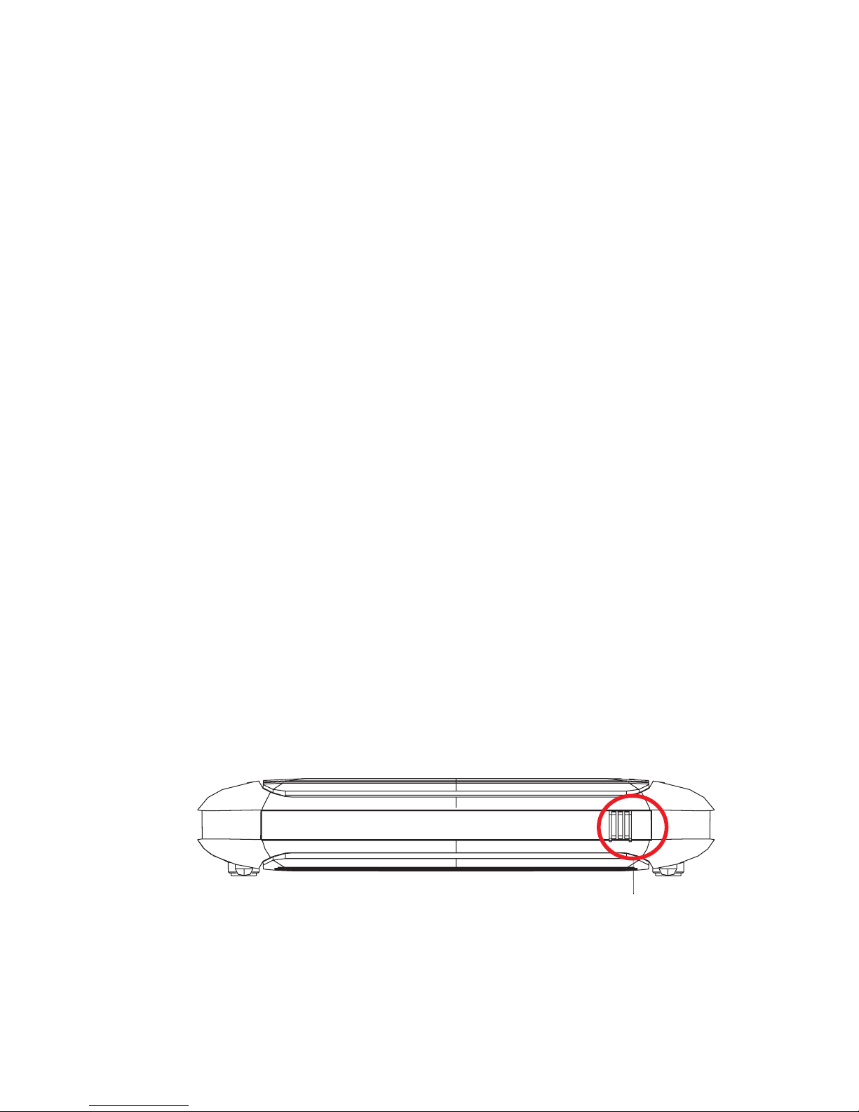
The Router includes an LED display on the top panel for system power
and port indications that simplifies installation and network
troubleshooting.
The Router has a WLAN On/Off button on the front panel, press this
button to turn on/turn off the wireless function.
Figure 2-1. Front Panel
WLAN On Off/
Page 12

I
NSTALLATION
2-4
The Router contains the following ports on the rear panel:
Figure 2-2. Rear Panel
Item Description
DSL Port Connect your ADSL line to this port.
4 LAN Ports Fast Ethernet ports (RJ-45). Connect devices on your local
area network to these ports (i.e., a PC, hub, or switch).
USB Connect your USB storage device or printer to this port.
Power Connect the included power adapter to this inlet.
Warning: Using the wrong type of power adapter may
damage the Router.
Power
On/Off
Switch
Use this switch to turn on/off the power.
Reset Button Use this button to reset the Router and restore the default
factory settings. To reset without losing configuration settings,
see “Reboot” on page 4-76.
Phone1 and
Phone2
FXS ports for VoIP function.
Page 13
H
ARDWARE DESCRIPTION
2-5
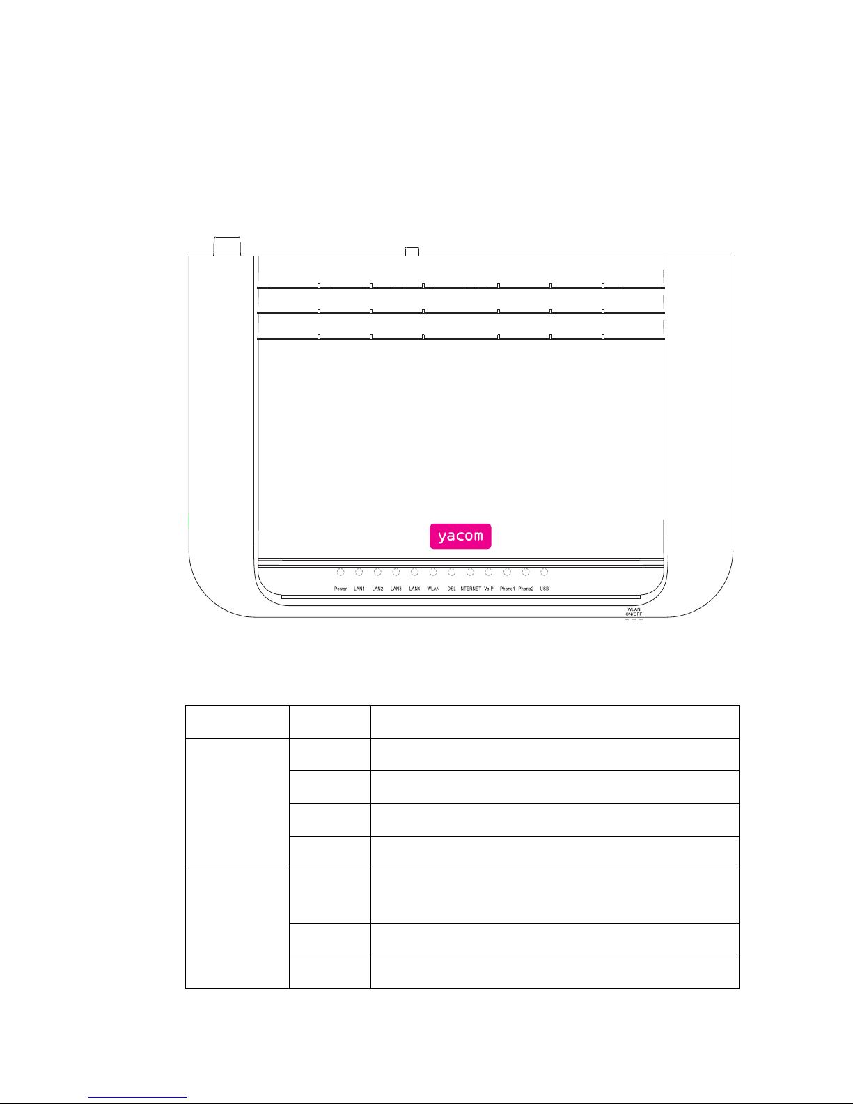
LED Indicators
The power and port LED indicators on the top panel are illustrated in the
following figure and table.
Figure 2-3. Top View
LED Status Description
Power Green Normal operation.
Red POST (Power On Self Test) failure.
Off Power off.
Purple Device is under Firmware Auto Upgrade.
LAN1 to
LAN4
On Ethernet connection is established.
Flashing The indicated LAN port is transmitting data.
Off There is no LAN connection on the port.
Page 14

I
NSTALLATION
2-6
WLAN Flashing The WLAN port is sending or receiving data.
Off WLAN disabled.
DSL On For PPPoA or PPPoE connections this LED will be
on when PPP authentication is successful.
Off PPP authentication failed or your connection is not
using PPPoA or PPPoE.
Slow
Blink
When the Router detects network clock and start
DSL negotiation.
Fast
Blink
When the Router is in its final stage of link
negotiation.
Internet On ADSL connection is functioning correctly.
Flashing The Router is establishing an ADSL link.
Off ADSL connection is not established.
VoIP On Your VoIP account registration was completed
successfully.
Flashing Your VoIP account registration failed.
Off The Router does not have any registration
information for an Internet telephony provider.
Phone1/
Phone2
On The phone is OFF-Hook, i.e., call in progress.
Flashing Incoming call.
Off No call in progress.
USB On USB device is connected to this port and USB
function is enabled through management interface.
Off No connection.
LED Status Description
Page 15

ISP S
ETTINGS
2-7
ISP Settings
Please collect the following information from your ISP before setting up
the Router:
• ISP account user name and password
• VoIP account information
• Protocol, encapsulation and VPI/VCI circuit numbers
•DNS server address
• IP address, subnet mask and default gateway (for fixed IP users only)
Connect the System
The Router can be positioned at any convenient location in your office or
home. It can also be wall-mounted. See “Wall Mounting” on page 2-2.
No special wiring or cooling requirements are needed. You should,
however, comply with the following guidelines:
• Keep the Router away from any heating devices.
• Do not place the Router in a dusty or wet environment.
You should also remember to turn off the power, remove the power cord
from the outlet, and keep your hands dry when you install the Router.
Page 16

I
NSTALLATION
2-8
Connect the ADSL Line
Connect the supplied grey ADSL cable from the port labelled DSL on the
splitter to the DSL port on your Router. When inserting the plug, be sure
the tab on the plug clicks into position to ensure that it is properly seated.
Attach to Your Network Using Ethernet Cabling
The four LAN ports on the Router auto-negotiate the connection speed to
10 Mbps or 100 Mbps, as well as the transmission mode to half duplex or
full duplex.
Use RJ-45 cables to connect any of the four LAN ports on the Router to
an Ethernet adapter on your PC. Otherwise, cascade any of the LAN ports
on the Router to an Ethernet hub or switch, and then connect your PC or
other network equipment to the hub or switch. When inserting an RJ-45
connector, be sure the tab on the connector clicks into position to ensure
that it is properly seated.
Warning: Do not plug a phone jack connector into an RJ-45 port. This
may damage the Router.
Note: Use 100-ohm shielded or unshielded twisted-pair cable with RJ-45
connectors for all Ethernet ports. Category 5 cable is
recommended. Make sure each twisted-pair cable length does not
exceed 100 meters (328 feet).
Page 17

C
ONNECT THE SYSTEM
2-9
Connect the Power Adapter
Plug the power adapter into the power socket on the rear of the Router,
and the other end into a power outlet.
Check the power indicator on the front panel is lit. If the power i
ndicator is
not lit, refer to
“Troubleshooting” on page A-1.
In case of a power input failure, the Router will automatically restart and
begin to operate once the input power is restored.
Page 18

3-1
C
HAPTER
3
C
ONFIGURING
C
LIENT
PC
After completing the hardware setup by connecting all your network
devices, you need to configure your computer to connect to the Router.
See:
“Windows 2000” on page 3-3
“Windows XP” on page 3-6
“Windows Vista” on page 3-8
or
“Configuring Your Macintosh Computer” on page 3-14
depending on your operating system.
Page 19

C
ONFIGURING CLIENT
PC
3-2
TCP/IP Configuration
To access the Internet through the Router, you must configure the network
settings of the computers in your LAN to use the same IP subnet as the
Router. The default IP settings for the Router are:
IP address: 192.168.2.1
Subnet mask: 255.255.255.0
Note: These settings can be changed to fit your network requirements,
but you must first configure at least one computer to access the
Router’s web configuration interface in order to make the required
changes. (See “Configuring the VoIP ADSL Router” on page 4-1
for instruction on configuring the Router.)
Page 20
W
INDOWS
2000
3-3
Windows 2000
1. On the Windows desktop, click Start/Settings/Network and
Dial-Up Connections.
2. Click the icon that
corresponds to the
connection to your Router.
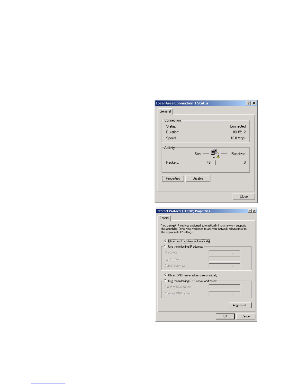
3. The connection status
screen will open. Click
Properties.
4. Double-click Internet
Protocol (TCP/IP).
5. If Obtain an IP
address automatically
and Obtain DNS server
address automatically
are already selected, your
computer is already
configured for DHCP. If
not, select this option.
Page 21
C
ONFIGURING CLIENT
PC
3-4
Disable HTTP Proxy
You need to verify that the “HTTP Proxy” feature of your web browser is
disabled. This is so that your browser can view the Router’s HTML
configuration pages. See page 3-6 for details.
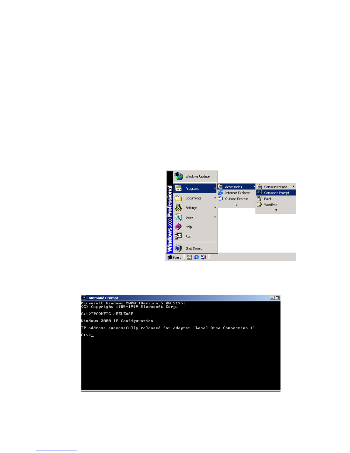
Obtain IP Settings from Your Router
Now that you have configured your computer to connect to your Router, it
needs to obtain new network settings. By releasing old DHCP IP settings
and renewing them with settings from your Router, you can verify that you
have configured your computer correctly.
1. On the Windows desktop,
click Start/Programs/
Accessories/
Command Prompt.
2. In the Command Prompt window, type ipconfig/release and press
the Enter key.
Page 22
W
INDOWS
2000
3-5
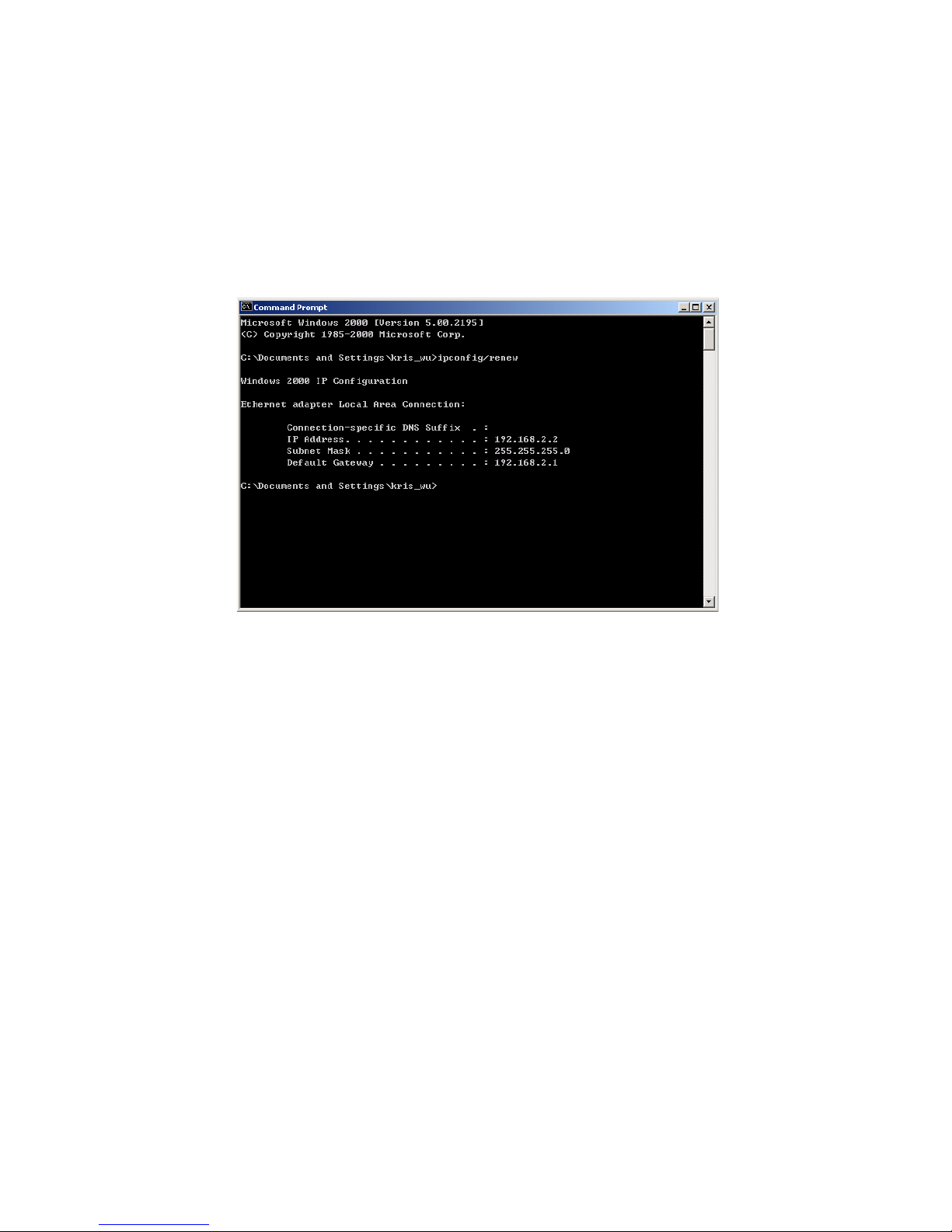
3. In the Command Prompt window, type ipconfig/renew and press
the Enter key. Verify that your IP Address is now 192.168.2.xxx, your
Subnet Mask is 255.255.255.0 and your Default Gateway is
192.168.2.1. These values confirm that your ADSL Router is
functioning.
4. Type exit and press the Enter key to close the Command Prompt
window.
Your computer is now configured to connect to the Router.
Page 23

C
ONFIGURING CLIENT
PC
3-6
Windows XP
1. On the Windows desktop, click Start/Control Panel.
2. In the Control Panel window, click Network and Internet
Connections.
3. The Network Connections window will open. Double-click the
connection for this device.
4. On the connection status screen, click Properties.
5. Double-click Internet Protocol (TCP/IP).
6. If Obtain an IP address automatically and Obtain DNS
server address automatically are already selected, your
computer is already configured for DHCP. If not, select this option.
Disable HTTP Proxy
You need to verify that the “HTTP Proxy” feature of your web browser is
disabled. This is so that your browser can view the Router’s HTML
configuration pages. Follow these steps to disable the HTTP proxy:
Open your web browser, go to Tools, Internet Options. Select the
Connections tab, click LAN Setting. Make sure the checkbox for Use a
proxy server for your LAN is not checked.
Page 24

W
INDOWS
XP
3-7
Obtain IP Settings From Your Router
Now that you have configured your computer to connect to your Router, it
needs to obtain new network settings. By releasing old DHCP IP settings
and renewing them with settings from your Router, you can verify that you
have configured your computer correctly.
1. On the Windows desktop, click Start/Programs/Accessories/
Command Prompt.
2. In the Command Prompt window, type ipconfig/release and press
the Enter key.
3. Type ipconfig/renew and press the Enter key. Verify that your IP
Address is now 192.168.2.xxx, your Subnet Mask is 255.255.255.0 and
your Default Gateway is 192.168.2.1. These values confirm that your
ADSL router is functioning.
4. Close the Command Prompt window.
Your computer is now configured to connect to the Router.
Page 25
C
ONFIGURING CLIENT
PC
3-8
Windows Vista
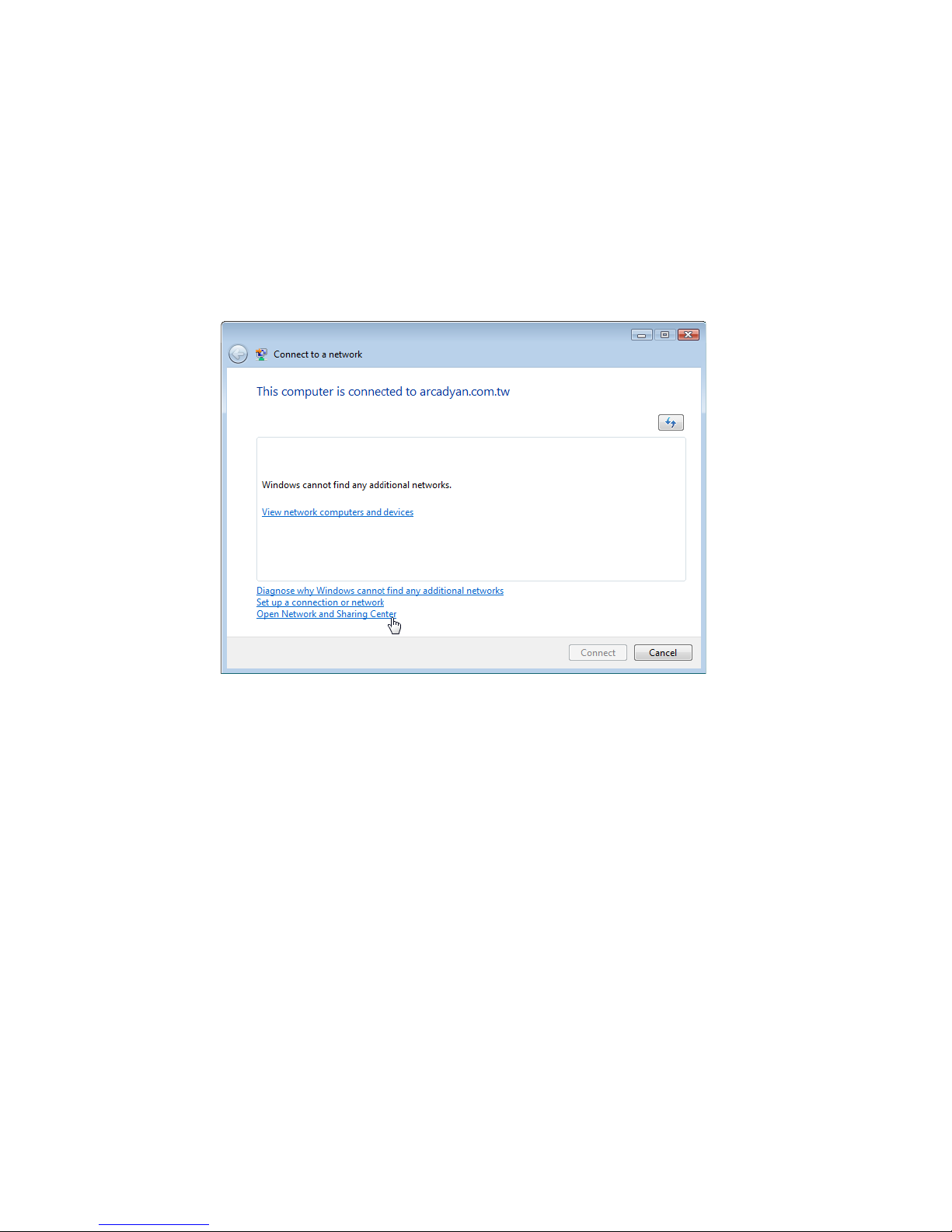
1. On the Windows desktop, click Start/Connet To.
2. The Connect to a network window will open. Click Open Network
and Sharing Center.
Page 26
W
INDOWS VISTA
3-9
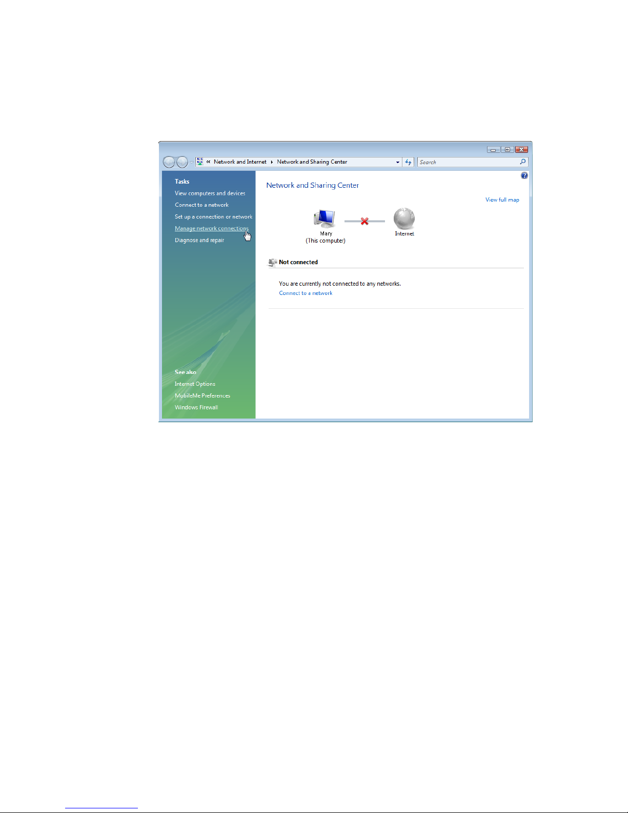
3. Click Manage network connections on the left menu bar of the
screen.
Page 27
C
ONFIGURING CLIENT
PC
3-10
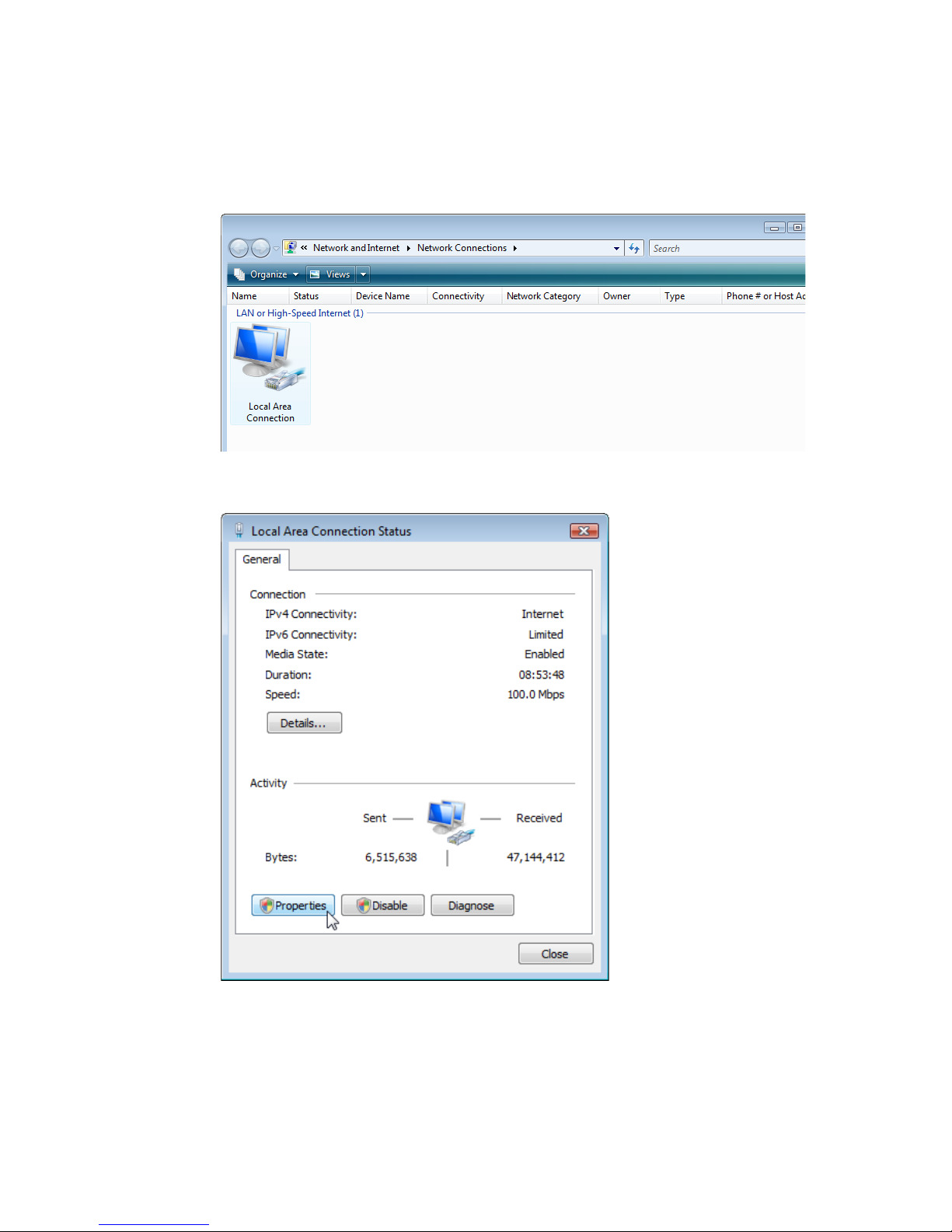
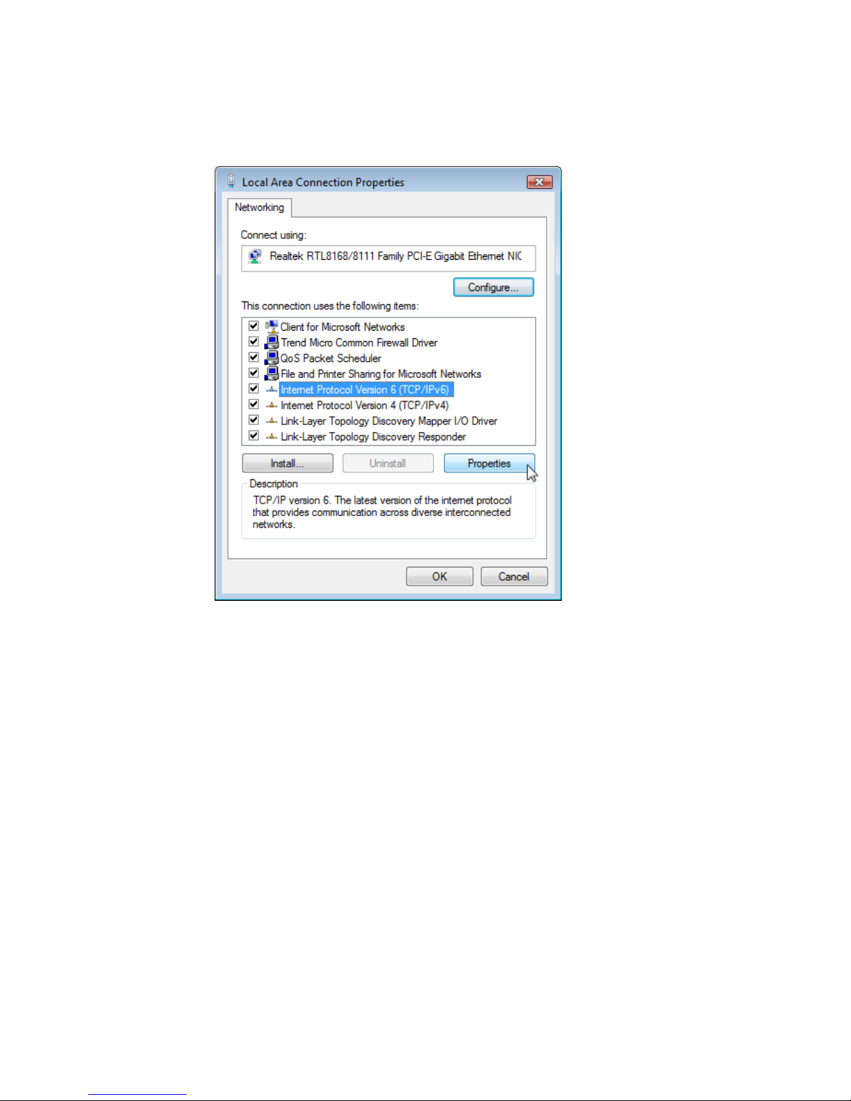
4. The LAN or High-Speed Internet window will open.
Double-click the connection for this device.
5. On the connection status screen, click Properties.
Page 28
W
INDOWS VISTA
3-11
6. Double-click Internet Protocol (TCP/IP).
Page 29
C
ONFIGURING CLIENT
PC
3-12
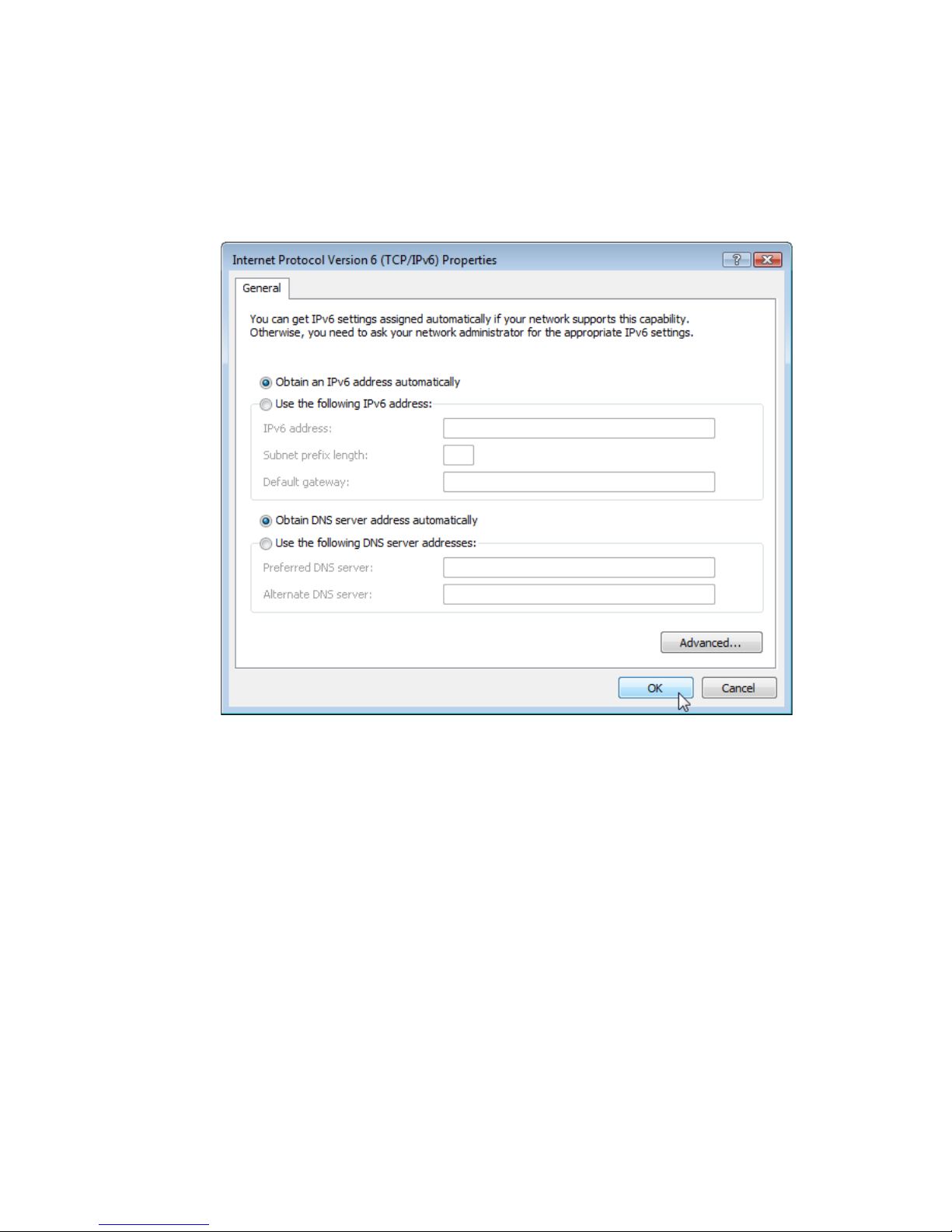
7. If Obtain an IPv6 address automatically and Obtain DNS
server address automatically are already selected, your
computer is already configured for DHCP. If not, select the options.
Disable HTTP Proxy
You need to verify that the “HTTP Proxy” feature of your web browser is
disabled. This is so that your browser can view the Router’s HTML
configuration pages. Follow these steps to disable the HTTP proxy:
Open your web browser, go to Tools, Internet Options. Select the
Connections tab, click LAN Setting. Make sure the checkbox for Use a
proxy server for your LAN is not checked.
Page 30

W
INDOWS VISTA
3-13
Obtain IP Settings From Your Router
Now that you have configured your computer to connect to your Router, it
needs to obtain new network settings. By releasing old DHCP IP settings
and renewing them with settings from your Router, you can verify that you
have configured your computer correctly.
1. On the Windows desktop, click Start/All Programs/
Accessories/Command Prompt.
2. In the Command Prompt window, type ipconfig/release and press
the Enter key.
3. Type ipconfig/renew and press the Enter key. Verify that your IP
Address is now 192.168.2.xxx, your Subnet Mask is 255.255.255.0 and
your Default Gateway is 192.168.2.1. These values confirm that your
ADSL router is functioning.
4. Close the Command Prompt window.
Your computer is now configured to connect to the Router.
Page 31

C
ONFIGURING CLIENT
PC
3-14
Configuring Your Macintosh Computer
You may find that the instructions here do not exactly match your
operating system. This is because these steps and screenshots were created
using Mac OS 10.2. Mac OS 7.x and above are similar, but may not be
identical to Mac OS 10.2.
Follow these instructions:
1. Pull down the Apple Menu . Click
System Preferences.
2. Double-click the Network icon in
the Systems Preferences window.
Page 32

C
ONFIGURING YOUR MACINTOSH COMPUTER
3-15
3. If Using DHCP Server
is already selected in the
Configure field, your
computer is already
configured for DHCP. If
not, select this option.
4. Your new settings are shown on the TCP/IP tab. Verify that your IP
Address is now 192.168.2.xxx, your Subnet Mask is 255.255.255.0 and
your Router is 192.168.2.1. These values confirm that your Router is
functioning.
5. Close the Network window.
Now your computer is configured to connect to the Router.
Disable HTTP Proxy
You need to verify that the “HTTP Proxy” feature of your web browser is
disabled. This is so that your browser can view the Router’s HTML
configuration pages. The following steps are for Internet Explorer.
Internet Explorer
1. Open Internet Explorer and click the Stop
button. Click Explorer/Preferences.
2. In the Internet Explorer Preferences window,
under Network, select Proxies.
Page 33

C
ONFIGURING CLIENT
PC
3-16
3. Uncheck all check boxes and click OK.
Page 34

4-1
C
HAPTER
4
C
ONFIGURING THE
V
O
IP ADSL R
OUTER
After you have configured TCP/IP on a client computer, you can
configure the VoIP ADSL Router using your web browser.
To access the Router’s management interface, enter the default IP address
of the Router in your web browser: http://192.168.2.1.
Enter the default password: admin, and click Login.
Note: Passwords can contain from 3~12 alphanumeric characters and
are case sensitive.
Page 35

C
ONFIGURING THE VO
IP ADSL R
OUTER
4-2
Navigating the Management Interface
The management interface contains two main sections:
• Setup Wizard (see next page)
• Advanced Setup (see page 4-8)
Making Configuration Changes for the device: configurable parameters
have a dialog box or a drop-down list. Once a configuration change has
been made, click the Apply or Save Settings or Next button to enable
the new setting.
Note: To ensure proper screen refresh after a command entry, be sure
that Internet Explorer 5.5 is configured as follows: Under the
menu Tools/Internet Options/General/Temporary Internet
Files/Settings, the setting for “Check for newer versions of stored
pages” should be “Every visit to the page.”
Page 36

N
AVIGATING THE MANAGEMENT INTERFACE
4-3
Setup Wizard
On the left-hand side of the Home screen, the first menu item is Setup
Wizard. Use this function to quickly set up the Router. Click on Setup
Wizard, you will see the Parameters setting screen.
Parameters Setting
In Parameter Setting, select the Internet Service Provider (ISP).
• MER 8/32 (MAC Encapsulated Routing): using 1483 Bridging
(DHCP) mode
• Ya.com PPPoE 8/32: using VPI/VCI 8/32 PPPoE provided by
Yacom ISP
• Orange PPPoE 8/35: using VPI/VCI 8/35 PPPoE provided by
Orange ISP
This will automatically configure the Router with the correct Protocol,
Encapsulation and VPI/VCI settings for your ISP. Enter the user name
and password, then click Next.
MER 8/32
Page 37

C
ONFIGURING THE VO
IP ADSL R
OUTER
4-4
Ya.com PPPoE 8/32
Orange PPPoE 8/35
Enter the PPPoE settings provided by your ISP.
Parameter Description
Protocol 1483 Bridging (DHCP).
DNS Server Domain Name Servers are used to map a domain
name (e.g., www.somesite.com) to the equivalent
numerical IP address. Your ISP should provide
the IP address of a Domain Name Server. Enter
the IP address here.
VPI/VCI Virtual Path Identifier (VPI) and Virtual Circuit
Identifier (VCI) used by your ISP.
Encapsulation Select the encapsulation type used by your ISP
from the drop-down list.
Page 38

N
AVIGATING THE MANAGEMENT INTERFACE
4-5
Parameter Description
Protocol PPPoE.
VPI/VCI Virtual Path Identifier (VPI) and Virtual Circuit
Identifier (VCI) used by your ISP.
Encapsulation Select the encapsulation type used by your ISP from
the drop-down list.
Username Enter the user name here.
Password Enter the password here.
Confirm Password Confirm Password.
Page 39

C
ONFIGURING THE VO
IP ADSL R
OUTER
4-6
Confirm
The Confirm screen shows a summary of the configuration parameters.
Check all the parameters are correct on this screen.
Parameter Description
ADSL Operation Mode
(WAN)
ATM Protocol The WAN protocol of your ISP. If you are unsure
about the selected protocol, check with your ISP.
VPI/VCI Virtual Path Identifier (VPI) and Virtual Circuit
Identifier (VCI). If you are unsure the VPI/VCI
values are correct check with your ISP.
AAL5 Encapsulation Shows the packet encapsulation type. If you are
unsure the selected Encapsulation is correct check
with your ISP. Go to page 4-21 for a detailed
description.
ISP Parameters
Username The ISP assigned user name.
Password The password (hidden).
Page 40

N
AVIGATING THE MANAGEMENT INTERFACE
4-7
If the parameters are correct, click Finish to save these settings.
Your Router is now set up. Go to “Troubleshooting” on page A-1 if you
cannot make a connection to the Internet.
DHCP Parameters
Function Shows if DHCP is enabled or disabled.
Default Gateway WAN gateway (only displayed if you have static IP).
Subnet Mask WAN subnet mask (only displayed if you have static
IP).
Name Server 1 WAN IP address (only displayed if you have static
IP).
Name Server 2 WAN IP address (only displayed if you have static
IP).
Start IP Address Specify the start IP address of the DHCP pool. Do
not include the gateway address of the Router in the
client address pool. If you change the pool range,
make sure the first three octets match the gateway’s
IP address, i.e., 192.168.2.xxx.
Number of IP Numbers of IP addresses in the IP address pool.
Parameter Description
Page 41

C
ONFIGURING THE VO
IP ADSL R
OUTER
4-8
Advanced Setup
The left-hand side displays the main menu and the righthand side shows descriptive information. The advanced
management interface contains the following main menu
items as described in the table below.
Menu Description
System Sets the local time zone, the password for administrator access, and
the IP address of a PC that will be allowed to manage the Router
remotely.
WAN Specifies the Internet connection settings.
LAN Sets the TCP/IP configuration for the Router LAN interface and
DHCP clients.
Wireless Configures the radio frequency, SSID, and security for wireless
communications.
NAT Configures Address Mapping, virtual server and special
applications.
Firewall Configures a variety of security and specialized functions including:
Access Control, URL blocking, Internet access control scheduling,
intruder detection, and DMZ.
ADSL Sets the ADSL operation type and shows the ADSL status.
IPTV Supports IPTV service if provided by your ISP.
VoIP Configures VoIP settings for the VoIP Router, and view VoIP
status log.
USB Connects USB devices, such as USB storage HD, and printer server
to the Router via the USB port located on the rear of the Router.
Page 42

N
AVIGATING THE MANAGEMENT INTERFACE
4-9
Tools Contains options to backup & restore the current configuration,
restore all configuration settings to the factory defaults, update
system firmware, or reset the system.
Status Provides WAN connection type and status, firmware and hardware
version numbers, system IP settings, as well as DHCP, NAT, and
firewall information. Displays the number of attached clients, the
firmware versions, the physical MAC address for each media
interface, and the hardware version and serial number. Shows the
security and DHCP client log.
Menu Description
Page 43

C
ONFIGURING THE VO
IP ADSL R
OUTER
4-10
System
This screen includes all the basic configuration tools for the Router, such
as time zone, password settings, and remote management.
• Enable or disable PPPoE passthrough function: select to enable or
disable.
Page 44

N
AVIGATING THE MANAGEMENT INTERFACE
4-11
Time Settings
For accurate timing of log entries and system events, you need to set the
time zone. Select your time zone from the drop-down list.
If daylight savings is used in your area, check the box to enable the
function.
If you want to automatically synchronize the Router with a public time
server, check the Enable Automatic Time Server Maintenance
box. Select the desired servers from the drop-down menus.
Page 45

C
ONFIGURING THE VO
IP ADSL R
OUTER
4-12
Login Settings
Use this screen to change the password for accessing the management
interface.
Passwords can contain from 3~12 alphanumeric characters and are case
sensitive. Leave the table empty if you don’t want to change the login
password. We highly recommend you to change management interface
password for safe network security.
Note: If you lost the password, or you cannot gain access to the user
interface, press the reset button on the rear panel, holding it down
for at least five seconds to restore the factory defaults.
The default password is admin.
Enter a maximum Idle Time Out (in minutes) to define a maximum period
of time for which the login session is maintained during inactivity. If the
connection is inactive for longer than the maximum idle time, it will
perform system logout, and you have to log in again to access the
management interface. (Default: 10 minutes)
Page 46

N
AVIGATING THE MANAGEMENT INTERFACE
4-13
Remote Management
By default, management access is only available to users on your local
network. However, you can also manage the Router from a remote host by
entering the IP address of a remote computer on this screen. Check the
Enabled check box, and enter the IP address of the Host Address.
Note: If you check Enable and specify an IP address of 0.0.0.0, any
remote host can manage the Router.
For remote management via WAN IP address you need to connect using
port 8080. Simply enter WAN IP address followed by :8080, for example,
211.20.16.1:8080.
Page 47

C
ONFIGURING THE VO
IP ADSL R
OUTER
4-14
DDNS
Dynamic Domain Name Service (DDNS) provides users on the Internet
with a method to tie their domain name to a computer or server. DDNS
allows your domain name to follow your IP address automatically by
having your DNS records changed when your IP address changes.
This DDNS feature is powered by DynDNS.org or TZO.com. With a
DDNS connection you can host your own web site, email server, FTP site,
and more at your own location even if you have a dynamic IP address.
Page 48

N
AVIGATING THE MANAGEMENT INTERFACE
4-15
WAN
Specify the WAN connection parameters provided by your Internet
Service Provider (ISP).
The Router supports the following mode:
•ATM PVC
ATM PVC
Select the ATM (Asynchronous Transfer Mode) virtual connection here.
Page 49

C
ONFIGURING THE VO
IP ADSL R
OUTER
4-16
ATM Interface: MAC Encapsulated Routing (MER 8/32): 1483 Bridging
(DHCP)
Parameter Description
IP Address Enter the IP address provided by your ISP.
Subnet Mask Enter the subnet mask address provided by your ISP.
Default Gateway Enter the gateway address provided by your ISP.
Primary DNS IP Enter the Primary DNS IP address provided by your
ISP.
Secondary DNS IP Enter the Secondary DNS IP address provided by your
ISP.
VPI/VCI Enter the Virtual Path Identifier (VPI) and Virtual
Circuit Identifier (VCI) supplied by your ISP.
Encapsulation Select the encapsulation used by ISP from the
drop-down list.
QoS Class ATM QoS classes including CBR, UBR and VBR
PCR/SCR/MBS QoS Parameters - PCR, SCR and MBS are configurable.
DHCP Client Check the box if you are receiving IP address
dynamically from your ISP.
Page 50

N
AVIGATING THE MANAGEMENT INTERFACE
4-17
ATM Interface: PPPoE (Ya.com PPPoE 8/32, Orange PPPoE 8/35)
Parameter Description
VPI/VCI Virtual Path Identifier (VPI) and Virtual Circuit
Identifier (VCI) supported by your ISP.
(Ya.com: 8/32, Orange: 8/35)
Encapsulation Select the encapsulation used by ISP from the
drop-down list.
QoS Class ATM QoS classes including CBR, UBR and VBR
PCR/SCR/MBS QoS Parameters - PCR, SCR and MBS are
configurable.
IP assigned by ISP Select Yes if your ISP automatically assigns the IP
address.
IP Address Enter the IP address provided by your ISP.
Subnet Mask Enter the subnet mask address provided by your ISP.
Primary DNS IP Enter the Primary DNS IP address provided by your
ISP.
Secondary DNS IP Enter the Secondary DNS IP address provided by your
ISP.
Connect Type Sets connection mode to always connected, automatic
or manual connection. Click Reconnect to
re-establish the connection.
Page 51

C
ONFIGURING THE VO
IP ADSL R
OUTER
4-18
Idle Time (Minute) Enter the maximum idle time for the Internet
connection. After this time has been exceeded the
connection will be terminated.
Username Enter user name.
Password Enter password.
Confirm Password Confirm password
MTU Leave the Maximum Transmission Unit (MTU) at the
default value (1492) unless you have a particular reason
to change it.
Parameter Description
Page 52

N
AVIGATING THE MANAGEMENT INTERFACE
4-19
LAN
Use the LAN menu to configure the LAN IP address and to enable the
DHCP server for dynamic client address allocation.
Page 53

C
ONFIGURING THE VO
IP ADSL R
OUTER
4-20
Parameter Description
LAN IP
IP Address The IP address of the Router.
IP Subnet Mask The subnet mask of the network.
Host Name Enter the name here.
DHCP Server To dynamically assign an IP address to client
PCs, enable this function.
VLAN Binding
LAN 1-4 This option allows you to change VLAN
membership of LAN ports 1-4. (See “IPTV”
on page 4-59 for configuring an IPTV
connection.)
DHCP Server Parameters
Address Pool Start IP Specify the start IP address of the DHCP pool.
Do not include the gateway address of the
Router in the client address pool. If you change
the pool range, make sure the first three octets
match the gateway’s IP address, i.e.,
192.168.2.xxx.
Address Pool End IP Specify the end IP address of the DHCP pool.
Lease Time Set the IP lease time. For home networks this
may be set to Forever, which means there is no
time limit on the IP address lease.
Domain Name If your network uses a domain name, enter it
here. Otherwise, leave this field blank.
DHCP Option 60
Vendor ID
Enter the ID here.
Page 54

N
AVIGATING THE MANAGEMENT INTERFACE
4-21
VLAN
The Router’s VLAN function can be used to create up to 4 VLAN
profiles. Once a VLAN profile is created interfaces can be assigned to the
VLAN profile. This is done by setting the VLAN binding.
Notes: 1. Only interfaces of IEEE 802 bridging type (LAN ports 1-4 and
1483 Bridging PVC’s) can be assigned to a VLAN.
2. By default LAN ports 1-3 are assigned to the “Default”
VLAN.
Click Add VLAN to create a profile.
Page 55

C
ONFIGURING THE VO
IP ADSL R
OUTER
4-22
VLAN Profile
Configure the VLAN settings in this screen.
• Description: Enter a description for the VLAN group, for example:
IPTV
• IP Address: Enter IP address for the VLAN.
• Subnet Mask: Enter Subnet Mask address for the VLAN.
• NAT Domain: Set NAT Domain to private or public.
• IGMP Snooping: Enabling it will turn on the feature that allows an
Ethernet switch to “listen in” on the IGMP conversation between
hosts and routers.
• IGMP Querier: Enabling this function will send out periodic IGMP
queries.
Page 56

N
AVIGATING THE MANAGEMENT INTERFACE
4-23
UPnP
The Universal Plug and Play architecture offers pervasive peer-to-peer
network connectivity of PCs of all form factors, intelligent appliances, and
wireless devices. UPnP enables seamless proximity network in addition to
control and data transfer among networked devices in the office, home
and everywhere within your network.
• Check the Enable radio button to activate the function.
Page 57

C
ONFIGURING THE VO
IP ADSL R
OUTER
4-24
Wireless
The Router also operates as a wireless access point, allowing wireless
computers to communicate with each other. To configure this function, all
you need to do is enable the wireless function, define the radio channel,
the domain identifier, and the security options. Click the Enable button to
activate the function.
• Enable or disable Wireless function: select to enable or disable the
wireless function.
• Secondary Wireless Module: check this box to enable the secondary
wireless module.
The Router supports two SSIDs - the primary and the secondary SSID.
If the wireless function is disable, both SSID will be disabled; if the
wireless function is enabled, then the primary SSID will be used by
default.
Page 58

N
AVIGATING THE MANAGEMENT INTERFACE
4-25
Channel and SSID
You must specify a common radio channel and SSID (Service Set ID) to
be used by the Router and all of its wireless clients. Be sure you configure
all of its clients to the same values.
Parameter Description
Primary This is the primary Service Set ID. The SSID must be the
same on the Router and all of its wireless clients. Check the
Hide box to disable the broadcasting of this SSID.
Secondary This is the secondary SSID, only works if the Secondary
wireless module is enabled. Check the Hide box to disable
the broadcasting of this SSID.
Wireless Mode This device supports both 11g and 11b wireless networks.
Make your selection depending on the type of wireless
network that you have.
Channel The radio channel used by the wireless Router and its clients
to communicate with each other. This channel must be the
same on the Router and all of its wireless clients.
The Router will automatically assign itself a radio channel, or
you may select one manually.
Page 59

C
ONFIGURING THE VO
IP ADSL R
OUTER
4-26
Security
To make your wireless network safe, you should turn on the security
function. The Router supports WEP (Wired Equivalent Privacy), WPA
(Wi-Fi Protected Access) and WPA2 security mechanisms.
Select the associated access point from the drop-down list.
The following security options are available:
• WPA/WPA2
•WPA2 only
• WPA only
•WEP
• Disabled
Notes: 1. By default WEP encryption is enabled for your network
security. The WEP key is printed on the sticker at the bottom
of the Router.
2. Selecting the Disabled option will turn off the security
function. We suggest that you turn on the security function to
protect your wireless communication.
Page 60

N
AVIGATING THE MANAGEMENT INTERFACE
4-27
WPA/WPA2
Wi-Fi Protected Access (WPA) combines temporal key integrity protocol
(TKIP) and 802.1X mechanisms. It provides dynamic key encryption and
802.1X authentication service. The Router supports both WPA and
WPA2.
Parameter Description
Select Virtual AP Select the primary or secondary SSID to which you
want to apply the security settings to.
Allowed Client Type Select WPA/WPA2.
Authentication Choose 802.1X or Pre-shared Key to use as the
authentication method.
•802.1X: for the enterprise network with a RADIUS
server. (see next page for details)
•Pre-shared key: for the SOHO network environment
without an authentication server.
Pre-shared key type Select the key type: Passphrase or Hex.
Pre-shared Key Enter the key here.
Page 61

C
ONFIGURING THE VO
IP ADSL R
OUTER
4-28
WPA/WPA2_with 802.1X
If 802.1X is used as the authentication method, then you should enable
this function for the Router.
Parameter Description
Authentication Select 802.1X.
Session Idle timeout Defines a maximum period of time for which the
connection is maintained during inactivity.
Re-Authentication
Period
Defines a maximum period of time for which the
authentication server will dynamically re-assign a
session key to a connected client.
Quiet Period Defines a maximum period of time for which the
Router will wait between failed authentications.
Server IP The IP address of your authentication server.
Server Port The port used for the authentication service.
Secret Key The secret key shared between the authentication
server and its clients.
NAS-ID Defines the request identifier of the Network Access
Server.
Page 62

N
AVIGATING THE MANAGEMENT INTERFACE
4-29
WPA2 Only
If you want to use only WPA2 for your wireless network security. Select
WPA2 Only, then set the detail settings.
Parameter Description
Select Virtual AP Select the primary or secondary SSID to which you
want to apply the security settings to.
Allowed Client Type Select WPA2 Only.
Authentication Choose 802.1X or Pre-shared Key to use as the
authentication method.
•802.1X: for the enterprise network with a RADIUS
server. (see next page for details)
•Pre-shared key: for the SOHO network environment
without an authentication server.
Pre-shared key type Select the key type to be used in the Pre-shared Key.
Pre-shared Key Enter the key here.
Page 63

C
ONFIGURING THE VO
IP ADSL R
OUTER
4-30
WPA2 Only_with 802.1X
If 802.1X is used in your network, then you should enable this function for
the Router.
Parameter Description
Authentication Select 802.1X.
Session Idle timeout Defines a maximum period of time for which the
connection is maintained during inactivity.
Re-Authentication
Period
Defines a maximum period of time for which the
authentication server will dynamically re-assign a
session key to a connected client.
Quiet Period Defines a maximum period of time for which the
Router will wait between failed authentications.
Server IP The IP address of your authentication server.
Server Port The port used for the authentication service.
Secret Key The secret key shared between the authentication
server and its clients.
NAS-ID Defines the request identifier of the Network Access
Server.
Page 64

N
AVIGATING THE MANAGEMENT INTERFACE
4-31
WPA Only
If you want to use only WPA for your wireless network security. Select
WPA Only, then set the detail settings.
Parameter Description
Select Virtual AP Select the primary or secondary SSID to which you
want to apply the security settings to.
Allowed Client Type Select WPA Only.
Authentication Choose 802.1X or Pre-shared Key to use as the
authentication method.
•802.1X: for the enterprise network with a RADIUS
server. (see next page for details)
•Pre-shared key: for the SOHO network environment
without an authentication server.
Pre-shared key type Select the key type to be used in the Pre-shared Key.
Pre-shared Key Enter the key here.
Page 65

C
ONFIGURING THE VO
IP ADSL R
OUTER
4-32
WPA Only_with 802.1X
If 802.1X is used in your network, then you should enable this function for
the Router.
Parameter Description
Authentication Select 802.1X.
Session Idle timeout Defines a maximum period of time for which the
connection is maintained during inactivity.
Re-Authentication
Period
Defines a maximum period of time for which the
authentication server will dynamically re-assign a
session key to a connected client.
Quiet Period Defines a maximum period of time for which the
Router will wait between failed authentications.
Server IP The IP address of your authentication server.
Server Port The port used for the authentication service.
Secret Key The secret key shared between the authentication
server and its clients.
NAS-ID Defines the request identifier of the Network Access
Server.
Page 66

N
AVIGATING THE MANAGEMENT INTERFACE
4-33
WEP
If you want to use WEP to protect your wireless network, you need to set
the same parameters for the Router and all your wireless clients.
You can automatically generate encryption keys using the passphrase
function, when Key Entry Method is set to Hex, check the Passphrase
box, and enter the string. Select the Default Key ID from the drop-down
menu and click SAVE SETTINGS.
Parameter
Description
Select Virtual AP Select the primary or secondary SSID to which you
want to apply the security settings to.
Allowed Client Type Select WEP.
WEP Mode Select 64 bit or 128 bit key to use for encryption.
Key Entry Method Select Hex or ASCII to use for encryption key
Key Provisioning Select Static if there is only one fixed key for
encryption. If you want to select Dynamic, you would
need to enable 802.1X function first.
Page 67

C
ONFIGURING THE VO
IP ADSL R
OUTER
4-34
Note: Before saving settings the key is shown in clear text. If you wireless
client does not have a passphrase utility make a note of the default
key before saving settings. This is so you can configure your
wireless client with the correct key.
To manually configure the encryption key, enter five hexadecimal pairs of
digits for each 64-bit key, or enter 13 pairs for the single 128-bit key.
(A hexadecimal digit is a number or letter in the range 0-9 or A-F.) The
passphrase can consist of up to 32 alphanumeric characters.
Page 68

N
AVIGATING THE MANAGEMENT INTERFACE
4-35
Access Control
Using the Access Control functionality, you can restrict access based on
MAC address. Each PC has a unique identifier known as a Medium Access
Control (MAC) address. With MAC filtering enabled, the computers
whose MAC address you have listed in the filtering table will be able to
connect (or will be denied access) to the Router.
• Enable MAC Filtering: select to enable or disable this function.
• Access Rule for registered MAC address: select to allow/deny access
for the registered MAC addresses. Selecting Allow means only MAC
addresses registered here will be able to connect to the Router.
Selecting Deny means only the MAC addresses registered here will be
denied access to the Router.
• MAC Filtering Table: you can enter up to 32 addresses here in the
table. Click Add currently associated MAC stations to quickly
copy the entry to the MAC Filtering table.
Page 69

C
ONFIGURING THE VO
IP ADSL R
OUTER
4-36
WDS
The Wireless Distribution System (WDS) provides a means to extend the
range of a Wireless Local Area Network (WLAN). WDS allows an Access
Point (AP) to establish a direct link to other APs and to allow stations to
roam freely within the area covered by the WDS.
• Enable WDS function: check this box to enable this function.
• Rescan: click this button to refresh the list of available access points.
Available access points will show up on the AP MAC Address Table, check
the box to add that particular access point to the WDS.
Page 70

N
AVIGATING THE MANAGEMENT INTERFACE
4-37
NAT
Network Address Translation (NAT) allows multiple users to access the
Internet sharing one public IP.
• Enable or disable NAT module function: select to enable or disable
this feature.
Page 71

C
ONFIGURING THE VO
IP ADSL R
OUTER
4-38
Address Mapping
Allows one or more public IP addresses to be shared by multiple internal
users. This also hides the internal network for increased privacy and
security. Enter the Public IP address you wish to share into the Global IP
field. Enter a range of internal IPs that will share the global IP into the
from field.
Page 72

N
AVIGATING THE MANAGEMENT INTERFACE
4-39
Virtual Server
If you configure the Router as a virtual server, remote users accessing
services such as web or FTP at your local site via public IP addresses can
be automatically redirected to local servers configured with private IP
addresses. In other words, depending on the requested service (TCP/UDP
port number), the Router redirects the external service request to the
appropriate server (located at another internal IP address).
For example, if you set Type/Public Port to TCP/80 (HTTP or web) and
the Private IP/Port to 192.168.2.2/80, then all HTTP requests from
outside users will be transferred to 192.168.2.2 on port 80. Therefore, by
just entering the IP address provided by the ISP, Internet users can access
the service they need at the local address to which you redirect them.
The more common TCP service ports include:
HTTP: 80, FTP: 21, Telnet: 23, and POP3: 110
A list of ports is maintained at the following link:
http://www.iana.org/assignments/port-numbers.
Page 73

C
ONFIGURING THE VO
IP ADSL R
OUTER
4-40
Special Application
Some applications require multiple connections, such as Internet gaming,
video-conferencing, and Internet telephony. These applications may not
work when Network Address Translation (NAT) is enabled. If you need to
run applications that require multiple connections, use these screens to
specify the additional public ports to be opened for each application.
• Popular applications: use the drop-down menu to quickly copy the
entry to the table.
Page 74

N
AVIGATING THE MANAGEMENT INTERFACE
4-41
NAT Mapping Table
This screen displays the current NAPT (Network Address Port
Translation) address mappings.
RIP sends routing-update messages at regular intervals and when the
network topology changes. When a router receives a routing update that
includes changes to an entry, it updates its routing table to reflect the new
route. RIP routers maintain only the best route to a destination. After
updating its routing table, the router immediately begins transmitting
routing updates to inform other network routers of the change.
Page 75

C
ONFIGURING THE VO
IP ADSL R
OUTER
4-42
Firewall
The Router’s firewall inspects packets at the application layer, maintains
TCP and UDP session information including time-outs and the number of
active sessions, and provides the ability to detect and prevent certain types
of network attacks.
Network attacks that deny access to a network device are called
Denial-of-Service (DoS) attacks. DoS attacks are aimed at devices and
networks with a connection to the Internet. Their goal is not to steal
information, but to disable a device or network so users no longer have
access to network resources.
The Router protects against the following DoS attacks: IP Spoofing, Land
Attack, Ping of Death, IP with zero length, Smurf Attack, UDP port
loopback, Snork Attack, TCP null scan, and TCP SYN flooding.
(For details see page 4-49.)
The firewall does not significantly affect system performance, so we advise
leaving it enabled to protect your network. Select Enable and click the
SAVE SETTINGS button.
Page 76

N
AVIGATING THE MANAGEMENT INTERFACE
4-43
Access Control
Access Control allows users to define the outgoing traffic permitted or
not-permitted through the WAN interface. The default is to permit all
outgoing traffic.
Parameter Description
Enable Filtering
Function
Select to enable or disable the filtering function.
Normal Filtering
Table
Displays the IP address (or an IP address range)
filtering table.
Page 77

C
ONFIGURING THE VO
IP ADSL R
OUTER
4-44
To add the PC to the filtering table:
1. Click Add PC on the Access Control screen.
2. Define the appropriate settings for client PC services on this Access
Control Add PC screen.
3. Click OK and then click SAVE SETTINGS to save your settings.
Page 78

N
AVIGATING THE MANAGEMENT INTERFACE
4-45
MAC Filter
The Router can also limit the access of hosts within the local area network
(LAN). The MAC Filtering Table allows the Router to enter up to 32 MAC
addresses that are not allowed access to the WAN port.
• MAC Address Control: select to enable or disable this function.
• Enter the MAC address in the space provided.
Page 79

C
ONFIGURING THE VO
IP ADSL R
OUTER
4-46
URL Blocking
The Router allows the user to block access to web sites by entering either a
full URL address or just a keyword. This feature can be used to protect
children from accessing violent or pornographic web sites. You can define
up to 30 sites here.
• Click Clear All to delete all items from the table.
Page 80

N
AVIGATING THE MANAGEMENT INTERFACE
4-47
Schedule Rule
You may filter Internet access for local clients based on rules. Each access
control rule may be activated at a scheduled time. Define the schedule on
the Schedule Rule screen, and apply the rule on the Access Control screen.
Page 81

C
ONFIGURING THE VO
IP ADSL R
OUTER
4-48
Follow these steps to add a schedule rule:
1. Click Add Schedule Rule on the Schedule Rule screen.
2. Define the appropriate settings for a schedule rule on this Edit
Schedule Rule screen.
3. Click OK and then click SAVE SETTINGS to save your settings.
Page 82

N
AVIGATING THE MANAGEMENT INTERFACE
4-49
Intrusion Detection
• Intrusion Detection Feature
Stateful Packet Inspection (SPI) and Anti-DoS firewall protection
(Default: Enabled) — The Intrusion Detection Feature of the Router
limits access for incoming traffic at the WAN port. When the SPI feature
is turned on, all incoming packets will be blocked except for those types
marked in the Stateful Packet Inspection section.
RIP Defect (Default: Enabled) — If an RIP request packet is not
acknowledged to by the Router, it will stay in the input queue and not be
released. Accumulated packets could cause the input queue to fill, causing
severe problems for all protocols. Enabling this feature prevents the
packets from accumulating.
Discard Ping to WAN (Default: Disabled) — Prevent a ping on the
Router’s WAN port from being routed to the network.
Scroll down to view more information.
Page 83

C
ONFIGURING THE VO
IP ADSL R
OUTER
4-50
Page 84

N
AVIGATING THE MANAGEMENT INTERFACE
4-51
• Stateful Packet Inspection
This is called a “stateful” packet inspection because it examines the
contents of the packet to determine the state of the communications; i.e., it
ensures that the stated destination computer has previously requested the
current communication. This is a way of ensuring that all communications
are initiated by the recipient computer and are taking place only with
sources that are known and trusted from previous interactions. In addition
to being more rigorous in their inspection of packets, stateful inspection
firewalls also close off ports until connection to the specific port is
requested.
When particular types of traffic are checked, only the particular type of
traffic initiated from the internal LAN will be allowed. For example, if the
user only checks FTP Service in the Stateful Packet Inspection section, all
incoming traffic will be blocked except for FTP connections initiated from
the local LAN.
Stateful Packet Inspection allows you to select different application types
that are using dynamic port numbers. If you wish to use the Stateful Packet
Inspection (SPI) to block packets, click on the Yes radio button in the
Enable SPI and Anti-DoS firewall protection field and then check
the inspection type that you need, such as Packet Fragmentation, TCP
Connection, UDP Session, FTP Service, H.323 Service, or TFTP Service.
• When hackers attempt to enter your network, we can
alert you by e-mail
Enter your email address. Specify your SMTP and POP3 servers, user
name, and password.
Page 85

C
ONFIGURING THE VO
IP ADSL R
OUTER
4-52
• Connection Policy
Enter the appropriate values for TCP/UDP sessions as described in the
following table.
Parameter Defaults Description
Fragmentation
half-open wait
10 sec Configures the number of seconds that a packet
state structure remains active. When the timeout
value expires, the Router drops the unassembled
packet, freeing that structure for use by another
packet.
TCP SYN wait 30 sec Defines how long the software will wait for a
TCP session to synchronize before dropping the
session.
TCP FIN wait 5 sec Specifies how long a TCP session will be
maintained after the firewall detects a FIN
packet.
TCP connection
idle timeout
3600
seconds
(1 hour)
The length of time for which a TCP session will
be managed if there is no activity.
UDP session idle
timeout
30 sec The length of time for which a UDP session will
be managed if there is no activity.
H.323 data channel
idle timeout
180 sec The length of time for which an H.323 session
will be managed if there is no activity.
Page 86

N
AVIGATING THE MANAGEMENT INTERFACE
4-53
• DoS Criteria and Port Scan Criteria
Set up DoS and port scan criteria in the spaces provided (as shown below).
Note: The firewall does not significantly affect system performance, so
we advise enabling the prevention features to protect your
network.
Parameter Defaults Description
Total incomplete
TCP/UDP sessions
HIGH
300
sessions
Defines the rate of new unestablished sessions
that will cause the software to start deleting
half-open sessions.
Total incomplete
TCP/UDP sessions
LOW
250
sessions
Defines the rate of new unestablished sessions
that will cause the software to stop deleting half-
open sessions.
Incomplete
TCP/UDP sessions
(per min) HIGH
250
sessions
Maximum number of allowed incomplete
TCP/UDP sessions per minute.
Incomplete
TCP/UDP sessions
(per min) LOW
200
sessions
Minimum number of allowed incomplete
TCP/UDP sessions per minute.
Maximum incomplete
TCP/UDP sessions
number from same
host
10 Maximum number of incomplete TCP/UDP
sessions from the same host.
Incomplete
TCP/UDP sessions
detect sensitive time
period
300
msec
Length of time before an incomplete
TCP/UDP session is detected as incomplete.
Maximum half-open
fragmentation packet
number from same
host
30 Maximum number of half-open fragmentation
packets from the same host.
Half-open
fragmentation detect
sensitive time period
10000
msec
Length of time before a half-open
fragmentation session is detected as half-open.
Flooding cracker
block time
300
second
Length of time from detecting a flood attack to
blocking the attack.
Page 87

C
ONFIGURING THE VO
IP ADSL R
OUTER
4-54
DMZ
If you have a client PC that cannot run an Internet application properly
from behind the firewall, you can open the client up to unrestricted
two-way Internet access. Enter the IP address of a DMZ (Demilitarized
Zone) host on this screen. Adding a client to the DMZ may expose your
local network to a variety of security risks, so only use this option as a last
resort.
• Enable DMZ: select to enable or disable this function.
Page 88

N
AVIGATING THE MANAGEMENT INTERFACE
4-55
ADSL
ADSL (Asymmetric Digital Subscriber Line) is designed to deliver more
bandwidth downstream (from the central office to the customer site) than
upstream. This section is used to configure the ADSL operation type and
shows the ADSL status.
ADSL Parameters
This screen is designed for the engineer to test the ADSL loop condition.
Therefore, it is advised that users should not change the settings here at all.
Parameter Description
Operation Mode • Automatic
• T1.413 Issue 2
• G.992.1 (G.DMT)
• G.992.3 (ADSL2)
• G.992.5 (ADSL2+)
Page 89

C
ONFIGURING THE VO
IP ADSL R
OUTER
4-56
ADSL Status
The Status screen displays information on connection line status, data rate,
operation data and defect indication, and statistics.
Scroll down to view more information.
Page 90

N
AVIGATING THE MANAGEMENT INTERFACE
4-57
The following items are included on the information screen:
Parameter Description
Status
Line Status Shows the current status of the ADSL line connection.
Data Rate
Upstream Maximum upstream data rate.
Downstream Maximum downstream data rate.
Operation Data/Defect Indication
Noise Margin Maximum upstream and downstream noise margin.
Output Power Maximum fluctuation in the output power.
Attenuation Maximum reduction in the strength of the upstream and
downstream signal.
Fast Path FEC
Correction
There are two latency paths that may be used: fast and
interleaved. For either path, a forward error correction
(FEC) scheme is employed to ensure higher data integrity.
For maximum noise immunity, an interleaver may be used
to supplement FEC.
Interleaved Path
FEC Correction
An interleaver is basically a buffer used to introduce a
delay, allowing for additional error correction techniques
to handle noise. Interleaving slows the data flow and may
not be optimal for real-time signals such as video
transmission.
Fast Path CRC Error The number of Fast Path Cyclic Redundancy Check
errors.
Interleaved Path
CRC Error
The number of Interleaved Path Cyclic Redundancy
Check errors.
Loss of Signal
Defect
Momentary signal discontinuities.
Loss of Frame
Defect
Failures due to loss of frames.
Loss of Power
Defect
Failures due to loss of power.
Fast Path HEC
Error
Fast Path Header Error Concealment errors.
Page 91

C
ONFIGURING THE VO
IP ADSL R
OUTER
4-58
Interleaved Path
HEC Error
Interleaved Path Header Error Concealment errors.
Statistics (Superframes represent the highest level of data
presentation. Each superframe contains regular ADSL
frames, one of which is used to provide superframe
synchronization, identifying the start of a superframe.
Some of the remaining frames are also used for special
functions.)
Received
Superframes
Interleaved
Number of interleaved superframes received.
Transmitted
Superframes
Interleaved
Number of interleaved superframes transmitted.
Received
Superframes Fast
Number of fast superframes received.
Transmitted
Superframes Fast
Number of fast superframes transmitted.
Parameter Description
Page 92

N
AVIGATING THE MANAGEMENT INTERFACE
4-59
IPTV
Integrating this SIP-based VoIP Router with IP television delivers
interactive triple-play multimedia services of video, voice and data.
By connecting to a TV set-top-box, this VoIP Router with IPTV enabled
converges entertainment and communication to your TV environment.
If the IPTV function is enabled, the Router will automatically assign the
LAN 4 and ATM VC2 (1483 Bridging PVC) to the IPTV group of VLAN
port trunking. For detail settings, refer to “VLAN” on page 4-21.
Page 93

C
ONFIGURING THE VO
IP ADSL R
OUTER
4-60
VoIP
VoIP Account
The table lists the current VoIP account information.
Configure your VoIP account settings on this screen. Before you begin,
you will need to obtain the following settings from your service provider:
•User name
• Password
• Phone Number
•SIP Domain
•Realm
• SIP Proxy Server address and port
• SIP Registrar Server address and port
• Prefer Codec
Click on Add to add a new account (see next page for details).
Page 94

N
AVIGATING THE MANAGEMENT INTERFACE
4-61
• Check the Activated check box to enable the account. If the box is
unchecked then the account is disabled.
• Enter the following information provided by your service provider:
User ID, Display name, Password, Realm.
• Check the Use Auth ID check box, and enter the ID in the Auth ID
field.
• SIP Domain: enter the SIP domain in the field.
•The default Listen Port is 5060, we suggest leaving this value
unchanged.
•Select Listen VC from the drop-down menu, select Default VC Route
or VC2.
• Select the Proxy Server from the drop-down menu. The default
Proxy Port is 5060, we suggest leaving this value unchanged.
Page 95

C
ONFIGURING THE VO
IP ADSL R
OUTER
4-62
• Check Use Outbound Proxy, if you want to specify the outbound
proxy, and then enter the information in the Outbound Proxy
Server field, and the Outbound Proxy Port field.
•The default Registrar Expire time is 600. This is the time taken to
re-register with the registrar server.
• DTMF Mode: Dual Tone Multi-Frequency (DTMF) assigns a specific
frequency, consisting of two separate tones, to each key so that it can
be easily identified by a microprocessor. Select the mode to use.
• FAX Passthrough Codec: Select G.711u or G.711a.
• DNS SRV: select to enable or disable this function.
• Registration Query: select to enable or disable this function.
•Use the Up and Down buttons to change the codec priority. The
preferred codec goes at the top. Use the left and right arrows to
remove/add codecs from the list of selected codecs.
Codecs are used to convert an analogue voice signal to digitally encoded
version. Codecs vary in the sound quality, the bandwidth required, the
computational requirements, etc. You can specify which audio coding
Page 96

N
AVIGATING THE MANAGEMENT INTERFACE
4-63
process to use. The following codecs are supported:
•PCMA
• G.729
• G.726-40
• G.726-32
• G.726-24
• G.726-16
Extensions IN
You can configure the settings for Phone 1 and Phone 2 on this screen.
• Answer calls for all numbers: Check the boxes to activate the Answer
calls for all numbers function for Phone 1 and Phone 2.
Page 97

C
ONFIGURING THE VO
IP ADSL R
OUTER
4-64
Extensions OUT
You can configure the settings for Phone 1 and Phone 2 on this screen.
Parameter Description
Priority phone
number
Select a priority phone number to assign to the phone.
This should be your VoIP phone number. The
extension number selected will be the default number
used for making outgoing calls. You will also be able
to receive phone calls for this number.
Alternative phone
number
Select an alternative phone number to assign to the
phone. This could be your PSTN number (select
PSTN) or a secondary VoIP phone account.
Assigning an additional number allows you to receive
phone calls for this number. By default outgoing calls
are via the Priority phone number. However in the
event calling is not possible via the Priority phone
number, the call will be routed via this number.
Page 98

N
AVIGATING THE MANAGEMENT INTERFACE
4-65
Phone
You can configure four settings for the VoIP phones, phone 1 and
phone 2, on this screen.
• Echo Canceller: this feature filters out echoes occurred during periods
of active speech. Select to enable/disable this function.
• Voice Activity Detector: enabling this function means that only a
certain level of voice volume will be send out as voice packets. This
function is designed to save the bandwidth. Note that enabling the
Voice Activity Detector also enables Comfort Noise Generation
(CNG). CNG is a feature that generates comfort noise in the
background so you know the call is active.
• Call Waiting: enabling this function allows you to hear a second
incoming call while on a call.
• Caller ID Restriction (CLIR): allows you to block specified numbers.
Page 99

C
ONFIGURING THE VO
IP ADSL R
OUTER
4-66
Status
This screen displays the VoIP Account registration status.
• Click Clear to remove entries on the log.
• Click Refresh to update the list.
Page 100

N
AVIGATING THE MANAGEMENT INTERFACE
4-67
USB
The Router supports various server types. It allows you to connect a USB
storage device, or to share your printer over the network via the provided
USB port on the rear panel of this Router.
The following USB services are supported:
• File Server
•FTP Server
• Web-FTP Server
• Printer Server
Click Enable USB function to enable the server services. Click Update
Status to refresh the screen.
Notes: 1. Be sure the USB device is powered on and firmly connected to
the Router.
2. The USB services recognize the file system of FAT16/32
series.
 Loading...