

SMC Networks 7901BRA2 - annexe 1, ADSL2 Barricade SMC7901BRA2 User Manual


38 Tesla
Irvine, CA 92618
Phone: (949) 679-8000
Fast Ethernet Router with
built-in ADSL2/2+ Modem
From SMC’s line of award-winning connectivity solutions
August 2006
R.01 f/w 1.0

Information furnished is believed to be accurate and reliable. However, no responsibility is assumed by our
company for its use, nor for any infringements of patents or other rights of third parties which may result
from its use. No license is granted by implication or otherwise under any patent or patent rights of our
company. We reserve the right to change specifications at any time without notice.
Copyright © 2006 by
SMC Networks, Inc.
38 Tesla
Irvine, CA 92618
All rights reserved.
Tra demarks:
SMC is a registered trademark; and Barricade is a trademark of SMC Networks, Inc. Other product and
company names are trademarks or registered trademarks of their respective holders.

i
L
IMITED
W
ARRANTY
Limited Warranty Statement: SMC Networks, Inc. (“SMC”) warrants its products to be
free from defects in workmanship and materials, under normal use and service, for the
applicable warranty term. All SMC products carry a standard 90-day limited warranty from
the date of purchase from SMC or its Authorized Reseller. SMC may, at its own discretion,
repair or replace any product not operating as warranted with a similar or functionally
equivalent product, during the applicable warranty term. SMC will endeavor to repair or
replace any product returned under warranty within 30 days of receipt of the product.
The standard limited warranty can be upgraded to a Limited Lifetime* warranty by registering
new products within 30 days of purchase from SMC or its Authorized Reseller. Registration
can be accomplished via the enclosed product registration card or online via the SMC web
site. Failure to register will not affect the standard limited warranty. The Limited Lifetime
warranty covers a product during the Life of that Product, which is defined as the period of
time during which the product is an “Active” SMC product. A product is considered to be
“Active” while it is listed on the current SMC price list. As new technologies emerge, older
technologies become obsolete and SMC will, at its discretion, replace an older product in its
product line with one that incorporates these newer technologies. At that point, the obsolete
product is discontinued and is no longer an “Active” SMC product. A list of discontinued
products with their respective dates of discontinuance can be found at:
http://www.smc.com/index.cfm?action=customer_service_warranty.
All products that are replaced become the property of SMC. Replacement products may be
either new or reconditioned. Any replaced or repaired product carries either a 30-day limited
warranty or the remainder of the initial warranty, whichever is longer. SMC is not responsible
for any custom software or firmware, configuration information, or memory data of
Customer contained in, stored on, or integrated with any products returned to SMC pursuant
to any warranty. Products returned to SMC should have any customer-installed accessory or
add-on components, such as expansion modules, removed prior to returning the product for
replacement. SMC is not responsible for these items if they are returned with the product.
Customers must contact SMC for a Return Material Authorization number prior to returning
any product to SMC. Proof of purchase may be required. Any product returned to SMC
without a valid Return Material Authorization (RMA) number clearly marked on the outside
of the package will be returned to customer at customer’s expense. For warranty claims within
North America, please call our toll-free customer support number at (800) 762-4968.
Customers are responsible for all shipping charges from their facility to SMC. SMC is
responsible for return shipping charges from SMC to customer.

L
IMITED WARRANTY
ii
WARRANTIES EXCLUSIVE: IF AN SMC PRODUCT DOES NOT OPERATE AS
WARRANTED ABOVE, CUSTOMER’S SOLE REMEDY SHALL BE REPAIR OR
REPLACEMENT OF THE PRODUCT IN QUESTION, AT SMC’S OPTION. THE
FOREGOING WARRANTIES AND REMEDIES ARE EXCLUSIVE AND ARE IN
LIEU OF ALL OTHER WARRANTIES OR CONDITIONS, EXPRESS OR IMPLIED,
EITHER IN FACT OR BY OPERATION OF LAW, STATUTORY OR OTHERWISE,
INCLUDING WARRANTIES OR CONDITIONS OF MERCHANTABILITY AND
FITNESS FOR A PARTICULAR PURPOSE. SMC NEITHER ASSUMES NOR
AUTHORIZES ANY OTHER PERSON TO ASSUME FOR IT ANY OTHER
LIABILITY IN CONNECTION WITH THE SALE, INSTALLATION,
MAINTENANCE OR USE OF ITS PRODUCTS. SMC SHALL NOT BE LIABLE
UNDER THIS WARRANTY IF ITS TESTING AND EXAMINATION DISCLOSE THE
ALLEGED DEFECT IN THE PRODUCT DOES NOT EXIST OR WAS CAUSED BY
CUSTOMER’S OR ANY THIRD PERSON’S MISUSE, NEGLECT, IMPROPER
INSTALLATION OR TESTING, UNAUTHORIZED ATTEMPTS TO REPAIR, OR
ANY OTHER CAUSE BEYOND THE RANGE OF THE INTENDED USE, OR BY
ACCIDENT, FIRE, LIGHTNING, OR OTHER HAZARD.
LIMITATION OF LIABILITY: IN NO EVENT, WHETHER BASED IN CONTRACT
OR TORT (INCLUDING NEGLIGENCE), SHALL SMC BE LIABLE FOR
INCIDENTAL, CONSEQUENTIAL, INDIRECT, SPECIAL, OR PUNITIVE
DAMAGES OF ANY KIND, OR FOR LOSS OF REVENUE, LOSS OF BUSINESS, OR
OTHER FINANCIAL LOSS ARISING OUT OF OR IN CONNECTION WITH THE
SALE, INSTALLATION, MAINTENANCE, USE, PERFORMANCE, FAILURE, OR
INTERRUPTION OF ITS PRODUCTS, EVEN IF SMC OR ITS AUTHORIZED
RESELLER HAS BEEN ADVISED OF THE POSSIBILITY OF SUCH DAMAGES.
SOME STATES DO NOT ALLOW THE EXCLUSION OF IMPLIED WARRANTIES
OR THE LIMITATION OF INCIDENTAL OR CONSEQUENTIAL DAMAGES FOR
CONSUMER PRODUCTS, SO THE ABOVE LIMITATIONS AND EXCLUSIONS
MAY NOT APPLY TO YOU. THIS WARRANTY GIVES YOU SPECIFIC LEGAL
RIGHTS, WHICH MAY VARY FROM STATE TO STATE. NOTHING IN THIS
WARRANTY SHALL BE TAKEN TO AFFECT YOUR STATUTORY RIGHTS.
* SMC will provide warranty service for one year following discontinuance from the active
SMC price list. Under the limited lifetime warranty, internal and external power supplies, fans,
and cables are covered by a standard one-year warranty from date of purchase.
SMC Networks, Inc.
38 Tesla
Irvine, CA 92618

iii
C
OMPLIANCES
Federal Communication Commission Interference
Statement
This equipment has been tested and found to comply with the limits for a Class B digital
device, pursuant to Part 15 of the FCC Rules. These limits are designed to provide
reasonable protection against harmful interference in a residential installation. This
equipment generates, uses and can radiate radio frequency energy and, if not installed and
used in accordance with the instructions, may cause harmful interference to radio
communications. However, there is no guarantee that interference will not occur in a
particular installation. If this equipment does cause harmful interference to radio or
television reception, which can be determined by turning the equipment off and on, the user
is encouraged to try to correct the interference by one of the following measures:
• Reorient or relocate the receiving antenna.
• Increase the separation between the equipment and receiver.
• Connect the equipment into an outlet on a circuit different from that to which the receiver
is connected.
• Consult the dealer or an experienced radio/TV technician for help.
This device complies with Part 15 of the FCC Rules. Operation is subject to the following
two conditions: (1) This device may not cause harmful interference, and (2) this device must
accept any interference received, including interference that may cause undesired operation.
FCC Caution: Any changes or modifications not expressly approved by the party
responsible for compliance could void the user's authority to operate this equipment.
FCC - Part 68
This equipment complies with Part 68 of the FCC rules. This equipment comes with a label
attached to it that contains, among other information, the FCC registration number and
ringer equivalence number (REN) for this equipment. If requested, this information must be
provided to the telephone company.
This equipment uses the following jacks: RJ-11.
The REN is used to determine the quantity of devices that may be connected to the
telephone line. Excessive RENs on the telephone line may result in the devices not ringing in
response to an incoming call. In most, but not all areas, the sum of the RENs should not
exceed five (5.0). To be certain of the number of devices that may be connected to the line, as
determined by the total RENs, contact the telephone company to determine the maximum
REN for the calling area.

C
OMPLIANCES
iv
If this equipment causes harm to the telephone network, the telephone company will notify
you in advance that temporary discontinuance of service may be required. If advance notice is
not practical, the telephone company will notify the customer as soon as possible. Also, you
will be advised of your right to file a complaint with the FCC if you believe it is necessary.
The telephone company may make changes in its facilities, equipment, operations, or
procedures that will provide advance notice in order for you to make the necessary
modifications in order to maintain uninterrupted service.
If trouble is experienced with this equipment, please contact our company at the numbers
shown on back of this manual for repair and warranty information. If the trouble is causing
harm to the telephone network, the telephone company may request you to remove the
equipment from the network until the problem is resolved.
No repairs may be done by the customer.
This equipment cannot be used on telephone company-provided coin service. Connection to
Party Line Service is subject to state tariffs.
When programing and/or making test calls to emergency numbers:
• Remain on the line and briefly explain to the dispatcher the reason for the call.
• Perform such activities in off-peak hours such as early morning or late evenings.
The Telephone Consumer Protection Act of 1991 makes it unlawful for any person to use a
computer or other electronic device to send any message via a telephone facsimile machine
unless such message clearly contains, in a margin at the top or bottom of each transmitted
page or on the first page of the transmission the date and time it is sent and an identification
of the business, other entity, or individual sending the message and the telephone number of
the sending machine or such business, other entity, or individual.
In order to program this information into your facsimile, refer to your communications
software user manual.
EC Conformance Declaration
SMC contact for these products in Europe is:
SMC Networks Europe,
Edificio Conata II,
Calle Fructuós Gelabert 6-8, 2o, 4a,
08970 - Sant Joan Despí,
Barcelona, Spain.

C
OMPLIANCES
v
Marking by the above symbol indicates compliance with the Essential Requirements of the
R&TTE Directive of the European Union (1999/5/EC). This equipment meets the
following conformance standards:
• EN 55022
• EN 55024
• EN 61000-3-2
• EN 61000-3-3
• EN 60950-1
CSA Statement
This unit is to be used with an external power adaptor of a Class 2 or level 3 type and
Approved type suitable for use in the North America of equipment installation, having an
output voltage rating of 12 V dc, and output current rating of 1.0A or equivalent. The
external AC adapter must be complied with the requirements of LPS (Limited Power
Sources).

C
OMPLIANCES
vi
Safety Compliance
Wichtige Sicherheitshinweise (Germany)
1. Bitte lesen Sie diese Hinweise sorgfältig durch.
2. Heben Sie diese Anleitung für den späteren Gebrauch auf.
3. Vor jedem Reinigen ist das Gerät vom Stromnetz zu trennen. Verwenden Sie keine
Flüssigoder Aerosolreiniger. Am besten eignet sich ein angefeuchtetes Tuch zur
Reinigung.
4. Die Netzanschlu ßsteckdose soll nahe dem Gerät angebracht und leicht zugänglich sein.
5. Das Gerät ist vor Feuchtigkeit zu schützen.
6. Bei der Aufstellung des Gerätes ist auf sicheren Stand zu achten. Ein Kippen oder Fallen
könnte Beschädigungen hervorrufen.
7. Die Belüftungsöffnungen dienen der Luftzirkulation, die das Gerät vor Überhitzung
schützt. Sorgen Sie dafür, daß diese Öffnungen nicht abgedeckt werden.
8. Beachten Sie beim Anschluß an das Stromnetz die Anschlußwerte.
9. Verlegen Sie die Netzanschlußleitung so, daß niemand darüber fallen kann. Es sollte auch
nichts auf der Leitung abgestellt werden.
10. Alle Hinweise und Warnungen, die sich am Gerät befinden, sind zu beachten.
11. Wird das Gerät über einen längeren Zeitraum nicht benutzt, sollten Sie es vom Stromnetz
trennen. Somit wird im Falle einer Überspannung eine Beschädigung vermieden.
12. Durch die Lüftungsöffnungen dürfen niemals Gegenstände oder Flüssigkeiten in das
Gerät gelangen. Dies könnte einen Brand bzw. elektrischen Schlag auslösen.
13. Öffnen sie niemals das Gerät. Das Gerät darf aus Gründen der elektrischen Sicherheit
nur von authorisiertem Servicepersonal geöffnet werden.
14. Wenn folgende Situationen auftreten ist das Gerät vom Stromnetz zu trennen und von
einer qualifizierten Servicestelle zu überprüfen:
a. Netzkabel oder Netzstecker sind beschädigt.
b. Flüssigkeit ist in das Gerät eingedrungen.
c. Das Gerät war Feuchtigkeit ausgesetzt.
d. Wenn das Gerät nicht der Bedienungsanleitung entsprechend funktioniert oder Sie mit
Hilfe dieser Anleitung keine Verbesserung erzielen.
e. Das Gerät ist gefallen und/oder das Gehäuse ist beschädigt.
f. Wenn das Gerät deutliche Anzeichen eines Defektes aufweist.
15. Zum Netzanschluß dieses Gerätes ist eine geprüfte Leitung zu verwenden. Für einen
Nennstrom bis 6 A und einem Gerätegewicht größer 3 kg ist eine Leitung nicht leichter
als H05VV-F, 3G, 0.75 mm
2
einzusetzen.
Der arbeitsplatzbezogene Schalldruckpegel nach DIN 45 635 Teil 1000 beträgt 70 dB(A) oder
weniger.

vii
T
ABLE OF
C
ONTENTS
1 Introduction . . . . . . . . . . . . . . . . . . . . . . . . . . . . . . . . . .1-1
About the Barricade . . . . . . . . . . . . . . . . . . . . . . . . . . . . . . . . . . . . . . . . . 1-1
Features and Benefits . . . . . . . . . . . . . . . . . . . . . . . . . . . . . . . . . . . . . . . . 1-1
Applications . . . . . . . . . . . . . . . . . . . . . . . . . . . . . . . . . . . . . . . . . . . . . . . 1-2
2 Installation . . . . . . . . . . . . . . . . . . . . . . . . . . . . . . . . . . 2-1
Package Contents . . . . . . . . . . . . . . . . . . . . . . . . . . . . . . . . . . . . . . . . . . . 2-1
System Requirements . . . . . . . . . . . . . . . . . . . . . . . . . . . . . . . . . . . . . . . . 2-2
Hardware Description . . . . . . . . . . . . . . . . . . . . . . . . . . . . . . . . . . . . . . . 2-2
LED Indicators . . . . . . . . . . . . . . . . . . . . . . . . . . . . . . . . . . . . . . . 2-4
ISP Settings . . . . . . . . . . . . . . . . . . . . . . . . . . . . . . . . . . . . . . . . . . . . . . . . 2-5
Connect the System . . . . . . . . . . . . . . . . . . . . . . . . . . . . . . . . . . . . . . . . . 2-5
Connecting the ADSL Line . . . . . . . . . . . . . . . . . . . . . . . . . . . . . 2-5
Connecting the Network . . . . . . . . . . . . . . . . . . . . . . . . . . . . . . . 2-7
Connecting the Power Adapter . . . . . . . . . . . . . . . . . . . . . . . . . . 2-7
Software Installation . . . . . . . . . . . . . . . . . . . . . . . . . . . . . . . . . . . . . . . . . 2-8
Installing USB Driver . . . . . . . . . . . . . . . . . . . . . . . . . . . . . . . . . . 2-8
3 Configuring Client PC . . . . . . . . . . . . . . . . . . . . . . . . . 3-1
TCP/IP Configuration . . . . . . . . . . . . . . . . . . . . . . . . . . . . . . . . . . . . . . . 3-2
Windows 98/Me . . . . . . . . . . . . . . . . . . . . . . . . . . . . . . . . . . . . . . . . . . . . 3-2
Disable HTTP Proxy . . . . . . . . . . . . . . . . . . . . . . . . . . . . . . . . . . 3-4
Obtain IP Settings from Your Barricade . . . . . . . . . . . . . . . . . . . 3-6
Windows NT 4.0 . . . . . . . . . . . . . . . . . . . . . . . . . . . . . . . . . . . . . . . . . . . 3-7
Disable HTTP Proxy . . . . . . . . . . . . . . . . . . . . . . . . . . . . . . . . . . 3-9
Obtain IP Settings from Your Barricade . . . . . . . . . . . . . . . . . . . 3-9
Windows 2000 . . . . . . . . . . . . . . . . . . . . . . . . . . . . . . . . . . . . . . . . . . . . 3-11
Disable HTTP Proxy . . . . . . . . . . . . . . . . . . . . . . . . . . . . . . . . . 3-12
Obtain IP Settings from Your Barricade . . . . . . . . . . . . . . . . . . 3-12
Windows XP . . . . . . . . . . . . . . . . . . . . . . . . . . . . . . . . . . . . . . . . . . . . . . 3-14
Disable HTTP Proxy . . . . . . . . . . . . . . . . . . . . . . . . . . . . . . . . . 3-14
Obtain IP Settings from Your Barricade . . . . . . . . . . . . . . . . . . 3-14
Configuring Your Macintosh Computer . . . . . . . . . . . . . . . . . . . . . . . . 3-16
Disable HTTP Proxy . . . . . . . . . . . . . . . . . . . . . . . . . . . . . . . . . 3-17

T
ABLE OF CONTENTS
viii
4 Configuring the Barricade . . . . . . . . . . . . . . . . . . . . . . 4-1
Navigating the Management Interface . . . . . . . . . . . . . . . . . . . . . . . . . . 4-2
Making Configuration Changes . . . . . . . . . . . . . . . . . . . . . . . . . . 4-2
Setup Wizard . . . . . . . . . . . . . . . . . . . . . . . . . . . . . . . . . . . . . . . . . . . . . . 4-3
Time Zone . . . . . . . . . . . . . . . . . . . . . . . . . . . . . . . . . . . . . . . . . . 4-3
ADSL Settings . . . . . . . . . . . . . . . . . . . . . . . . . . . . . . . . . . . . . . . 4-4
Summary . . . . . . . . . . . . . . . . . . . . . . . . . . . . . . . . . . . . . . . . . . . . 4-5
ADSL Settings - Country or ISP Not Listed . . . . . . . . . . . . . . . . 4-7
Configuration Parameters . . . . . . . . . . . . . . . . . . . . . . . . . . . . . . . . . . . 4-15
System . . . . . . . . . . . . . . . . . . . . . . . . . . . . . . . . . . . . . . . . . . . . . 4-17
WAN . . . . . . . . . . . . . . . . . . . . . . . . . . . . . . . . . . . . . . . . . . . . . . 4-20
LAN . . . . . . . . . . . . . . . . . . . . . . . . . . . . . . . . . . . . . . . . . . . . . . 4-29
NAT . . . . . . . . . . . . . . . . . . . . . . . . . . . . . . . . . . . . . . . . . . . . . . 4-30
Routing . . . . . . . . . . . . . . . . . . . . . . . . . . . . . . . . . . . . . . . . . . . . 4-35
Firewall . . . . . . . . . . . . . . . . . . . . . . . . . . . . . . . . . . . . . . . . . . . . 4-40
SNMP . . . . . . . . . . . . . . . . . . . . . . . . . . . . . . . . . . . . . . . . . . . . . 4-53
UPnP . . . . . . . . . . . . . . . . . . . . . . . . . . . . . . . . . . . . . . . . . . . . . . 4-56
QoS . . . . . . . . . . . . . . . . . . . . . . . . . . . . . . . . . . . . . . . . . . . . . . . 4-57
ADSL . . . . . . . . . . . . . . . . . . . . . . . . . . . . . . . . . . . . . . . . . . . . . 4-60
DDNS . . . . . . . . . . . . . . . . . . . . . . . . . . . . . . . . . . . . . . . . . . . . . 4-64
Tools . . . . . . . . . . . . . . . . . . . . . . . . . . . . . . . . . . . . . . . . . . . . . . 4-65
Status . . . . . . . . . . . . . . . . . . . . . . . . . . . . . . . . . . . . . . . . . . . . . . 4-70
Finding the MAC Address of a Network Card . . . . . . . . . . . . . . . . . . . 4-73
Windows NT4/2000/XP . . . . . . . . . . . . . . . . . . . . . . . . . . . . . . 4-73
Macintosh . . . . . . . . . . . . . . . . . . . . . . . . . . . . . . . . . . . . . . . . . . 4-73
Linux . . . . . . . . . . . . . . . . . . . . . . . . . . . . . . . . . . . . . . . . . . . . . . 4-73

T
ABLE OF CONTENTS
ix
A Troubleshooting . . . . . . . . . . . . . . . . . . . . . . . . . . . . . A-1
B Cables . . . . . . . . . . . . . . . . . . . . . . . . . . . . . . . . . . . . . . B-1
Ethernet Cable . . . . . . . . . . . . . . . . . . . . . . . . . . . . . . . . . . . . . . . . . . . . . B-1
Specifications . . . . . . . . . . . . . . . . . . . . . . . . . . . . . . . . . . . . . . . . B-1
Wiring Conventions . . . . . . . . . . . . . . . . . . . . . . . . . . . . . . . . . . . B-1
RJ-45 Port Connection . . . . . . . . . . . . . . . . . . . . . . . . . . . . . . . . . B-2
Pin Assignments . . . . . . . . . . . . . . . . . . . . . . . . . . . . . . . . . . . . . . B-3
ADSL Cable Connection . . . . . . . . . . . . . . . . . . . . . . . . . . . . . . . . . . . . .B-5
Specifications . . . . . . . . . . . . . . . . . . . . . . . . . . . . . . . . . . . . . . . . B-5
Wiring Conventions . . . . . . . . . . . . . . . . . . . . . . . . . . . . . . . . . . . B-5
C Specifications . . . . . . . . . . . . . . . . . . . . . . . . . . . . . . . . C-1

T
ABLE OF CONTENTS
x

1-1
C
HAPTER
1
I
NTRODUCTION
Congratulations on your purchase of the ADSL2 BarricadeTM , hereafter
referred to as the “Barricade.” We are proud to provide you with a
powerful yet simple communication device for connecting your local area
network (LAN) to the Internet. For those who want to surf the Internet in
the most secure way, the Barricade provides a convenient and powerful
solution.
About the Barricade
The Barricade provides Internet access to multiple users by sharing a
single-user account. Support is provided for 10/100Mbps Fast Ethernet
devices. It is simple to configure and can be up and running in minutes.
Features and Benefits
• Built-in ADSL2/2+ modem - supports download speeds up to
24 Mbps
• Local network connection via 10/100 Mbps Ethernet port
or USB port.
• DHCP for dynamic IP configuration, and DNS for domain name
mapping
• Firewall with Stateful Packet Inspection, client privileges, intrusion
detection, and NAT

I
NTRODUCTION
1-2
• NAT also enables multi-user Internet access via a single user account,
and virtual server functionality (providing protected access to Internet
services such as web, FTP, email, and Telnet)
• QoS (Quality of Service) support
• Easy setup through a web browser on any operating system that
supports TCP/IP
Applications
Many advanced networking features are provided by the Barricade:
• Internet Access
This device supports Internet access through an ADSL connection.
Since many DSL providers use PPPoE or PPPoA to establish
communications with end users, the Barricade includes built-in clients
for these protocols, eliminating the need to install these services on
your computer.
• Shared IP Address
The Barricade provides Internet access for up to 253 users via a single
shared IP address. Using only one ISP account, multiple users on your
network can browse the web at the same time.

A
PPLICATIONS
1-3
•Virtual Server
If you have a fixed IP address, you can set the Barricade to act as a
virtual host for network address translation. Remote users access
various services at your site using a constant IP address. Then,
depending on the requested service (or port number), the Barricade
can route the request to the appropriate server (at another internal IP
address). This secures your network from direct attack by hackers, and
provides more flexible management by allowing you to change
internal IP addresses without affecting outside access to your
network.
• DMZ Host Support
Allows a networked computer to be fully exposed to the Internet.
This function is used when NAT and firewall security prevent an
Internet application from functioning correctly.
• Security
The Barricade supports security features that deny Internet access to
specified users, or filter all requests for specific services that the
administrator does not want to serve. The Barricade’s firewall also
blocks common hacker attacks, including IP Spoofing, Land Attack,
Ping of Death, IP with zero length, Smurf Attack, UDP port
loopback, Snork Attack, TCP null scan, and TCP SYN flooding.

I
NTRODUCTION
1-4

2-1
C
HAPTER
2
I
NSTALLATION
Before installing the ADSL2 BarricadeTM , verify that you have all the
items listed under the Package Contents list. Also be sure that you have all
the necessary cabling before installing the Barricade. After installing the
Barricade, refer to “Configuring the Barricade” on page 4-1.
Package Contents
After unpacking the Barricade, check the contents of the box to be sure
you have received the following items:
• SMC7901BRA2 ADSL2 Barricade
TM
• Power adapter
• One RJ-45 Ethernet cable
• One telephone patch cable (RJ-11)
• Printed quick installation guide
• Documentation CD
• Warranty Registration Card
Immediately inform your dealer in the event of any incorrect, missing, or
damaged parts. If possible, please retain the carton and original packing
materials in case there is a need to return the product.

I
NSTALLATION
2-2
System Requirements
You must meet the following minimum requirements:
• ADSL Internet Service installed.
• Ethernet adapter installed on your PC.
• TCP/IP network protocols installed on each PC that will access the
Internet.
• A Java enabled web browser such as Internet Explorer 5.5 or above,
Netscape 4.7 or above, Mozilla 1.7 or above and Firefox 1.0 or above.
Hardware Description
The Barricade contains an integrated ADSL modem and connects to the
Internet or to a remote site using its RJ-11 WAN port. It can be connected
directly to your PC or to a local area network using the Ethernet LAN
port. Also you can use the USB port for connecting this Barricade to your
PC.
Access speed to the Internet depends on your service type. Full-rate ADSL
provides up to 8 Mbps downstream and 1 Mbps upstream. G.lite (or
splitterless) ADSL provides up to 1.5 Mbps downstream and 512 kbps
upstream. ADSL2+ provides up to 24 Mbps downstream and 1 Mbps
upstream. However, you should note that the actual rate provided by
specific service providers may vary dramatically from these upper limits.
Data passing between devices connected to your local area network can
run at up to 100 Mbps over the Fast Ethernet port.
H
ARDWARE DESCRIPTION
2-3
The Barricade includes an LED display on the top for system power and
port indicators that simplify installation and network troubleshooting.
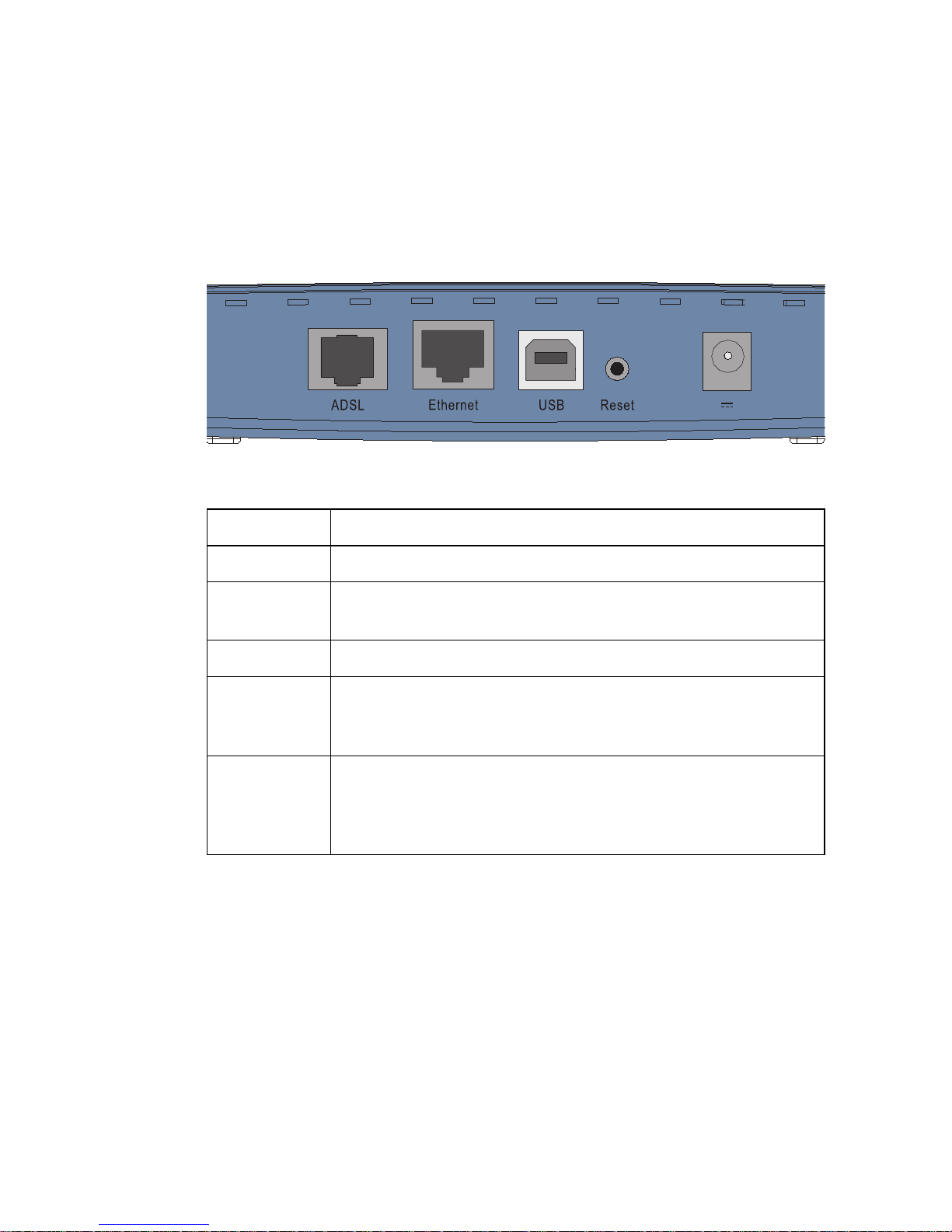
It also provides the following ports on the rear panel:
Figure 2-1. Rear Panel
Item Description
ADSL Port WAN port (RJ-11). Connect your ADSL line to this port.
Ethernet
Port
Fast Ethernet port (RJ-45). Connect the network device on
your local area network to this port (i.e., a PC, hub, or switch).
USB Port Connect your PC to this port for Internet access.
Reset Button Use this button to reset the power and restore the default
factory settings. To reset without losing configuration settings,
see “Reset” on page 4-69.
Power Inlet Connect the included power adapter to this inlet.
Warning:Using the wrong type of power adapter may
damage the Barricade.
12 1A
I
NSTALLATION
2-4
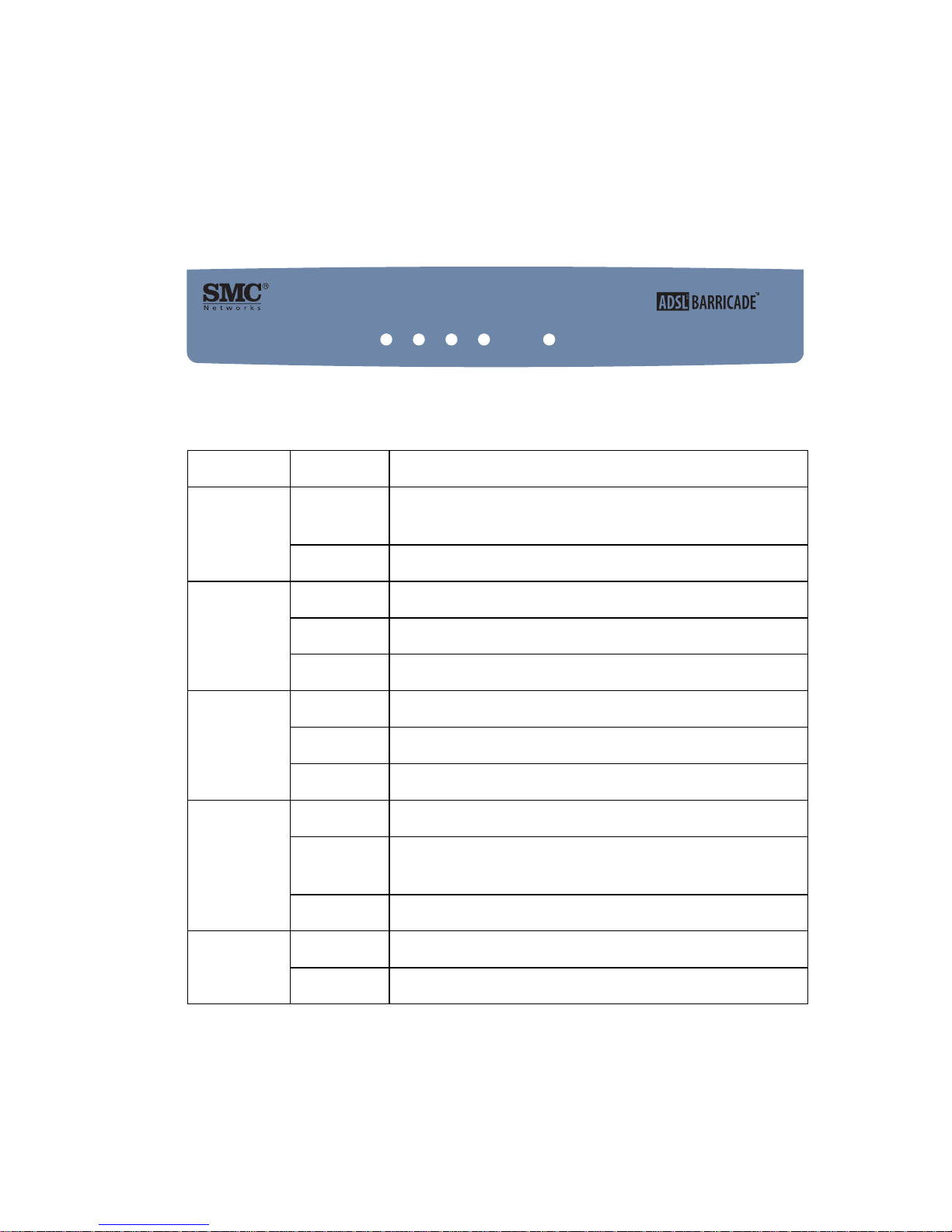
LED Indicators
The power and port LED indicators on the top are illustrated by the
following figure and table.
Figure 2-2. Top View
LED Status Description
Power On The SMC7901BRA2 ADSL Router is receiving
power. Normal operation.
Off Power off or failure.
LAN On Ethernet connection is established.
Flashing The LAN port is sending or receiving data.
Off There is no LAN connection on the port.
USB On USB connection is established.
Flashing The USB port is sending or receiving data.
Off There is no connection on this port.
ADSL
SYNC.
On ADSL connection is functioning correctly.
Flashing The SMC7901BRA2 ADSL Router is establishing an
ADSL link.
Off ADSL connection is not established.
ADSL
DATA
Flashing The ADSL port is sending or receiving data
Off No data being transferred.
2-port Annex AADSL2/2+ Modem Router
SMC7901BRA2
POWER
ADSL
SYNC
ADSL
DATALAN
USB

ISP S
ETTINGS
2-5
ISP Settings
Please collect the following information from your ISP before setting up
the Barricade:
• ISP account user name and password
• Protocol, encapsulation and VPI/VCI circuit numbers
•DNS server address
• IP address, subnet mask and default gateway (for fixed IP users only)
Connect the System
The Barricade can be positioned at any convenient location in your office
or home. No special wiring or cooling requirements are needed. You
should, however, comply with the following guidelines:
• Keep the Barricade away from any heating devices.
• Do not place the Barricade in a dusty or wet environment.
You should also remember to turn off the power, remove the power cord
from the outlet, and keep your hands dry when you install the Barricade.
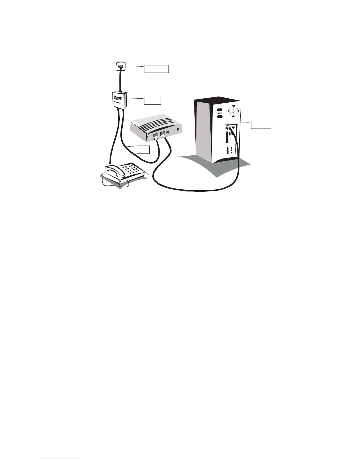
Connecting the ADSL Line
Connect the splitter to the phone line and the phone to the phone port of
the splitter. Using the black RJ-11 cable provided connect the ADSL port
of the Barricade to the ADSL port of the splitter. Refer to the below
illustration.
I
NSTALLATION
2-6
Figure 2-3. Connection Illustration
The splitter is required for connecting your Barricade and phone to the
same phone line. If you have a dedicated phone line for ADSL connect the
Barricade directly to the phone line.
Note: To prevent high frequency ADSL signals interfering with
telephone calls, each phone must be connected to the same phone
line through a splitter (also known as an ADSL microfilter).
Phone Line
Splitter
RJ 11-
Ethernet

C
ONNECT THE SYSTEM
2-7
Connecting the Network
Fast Ethernet Connection
Using the grey RJ-45 cable provided connect LAN port of the Barricade to
the network card of your computer or other network device, e.g., hub or
switch. The LAN LED will illuminate green to indicate a good link.
USB Connection
1. Select an available USB port on the PC.
2. Carefully insert the USB cable’s Type-A plug (i.e., the flat plug) into the
USB port and press until it is firmly seated in the port.
3. Insert the other end of the cable into the Barricade.
Connecting the Power Adapter
Plug the power adapter into the power socket on the rear of the Barricade,
and the other end into a power outlet. Check the power indicator on the
front panel is lit. If the power i
ndicator is not lit, refer to
“Troubleshooting” on page A-1.
In case of a power input failure, the Barricade will automatically restart and
begin to operate once the input power is restored.

I
NSTALLATION
2-8
Software Installation
Installing USB Driver
The USB Installation Wizard and Documentation CD that comes with the
package contains all the software, including the driver for the Barricade.
Any new or updated software can be downloaded from the SMC web site
at http://www.smc.com
.
Note: Installation processes such as this may require the use of your
original licensed copy of Windows. Please have your Windows CD
available BEFORE proceeding with the installation.
This installation method makes the process as simple and Plug-and-Play as
possible. Simply run the driver program, and insert your USB connector.
1. Insert the Installation Wizard and Documentation CD into your
CD-ROM drive.
2. Click the Install USB Driver button to begin the installation process.
3. Follow the on-screen instructions to complete the driver installation.

3-1
C
HAPTER
3
C
ONFIGURING
C
LIENT
PC
After completing hardware setup by connecting all your network devices,
you need to configure your computer to connect to the Barricade.
See:
“Windows 98/Me” on page 3-2
“Windows NT 4.0” on page 3-7
“Windows 2000” on page 3-11
“Windows XP” on page 3-14
or
“Configuring Your Macintosh Computer” on page 3-16
depending on your operating system.
C
ONFIGURING CLIENT
PC
3-2
TCP/IP Configuration
To access the Internet through the Barricade, you must configure the
network settings of the computers on your LAN to use the same IP subnet
as the Barricade. The default IP settings for the Barricade are:
IP Address: 192.168.2.1
Subnet Mask: 255.255.255.0
Note: These settings can be changed to fit your network requirements,
but you must first configure at least one computer to access the
Barricade’s web configuration interface in order to make the
required changes. (See “Configuring the Barricade” on page 4-1
for instruction on configuring the Barricade.)
Windows 98/Me
You may find that the instructions in this section do not exactly match
your version of Windows. This is because these steps and screen shots
were created from Windows 98. Windows Millennium Edition is similar,
but not identical, to Windows 98.
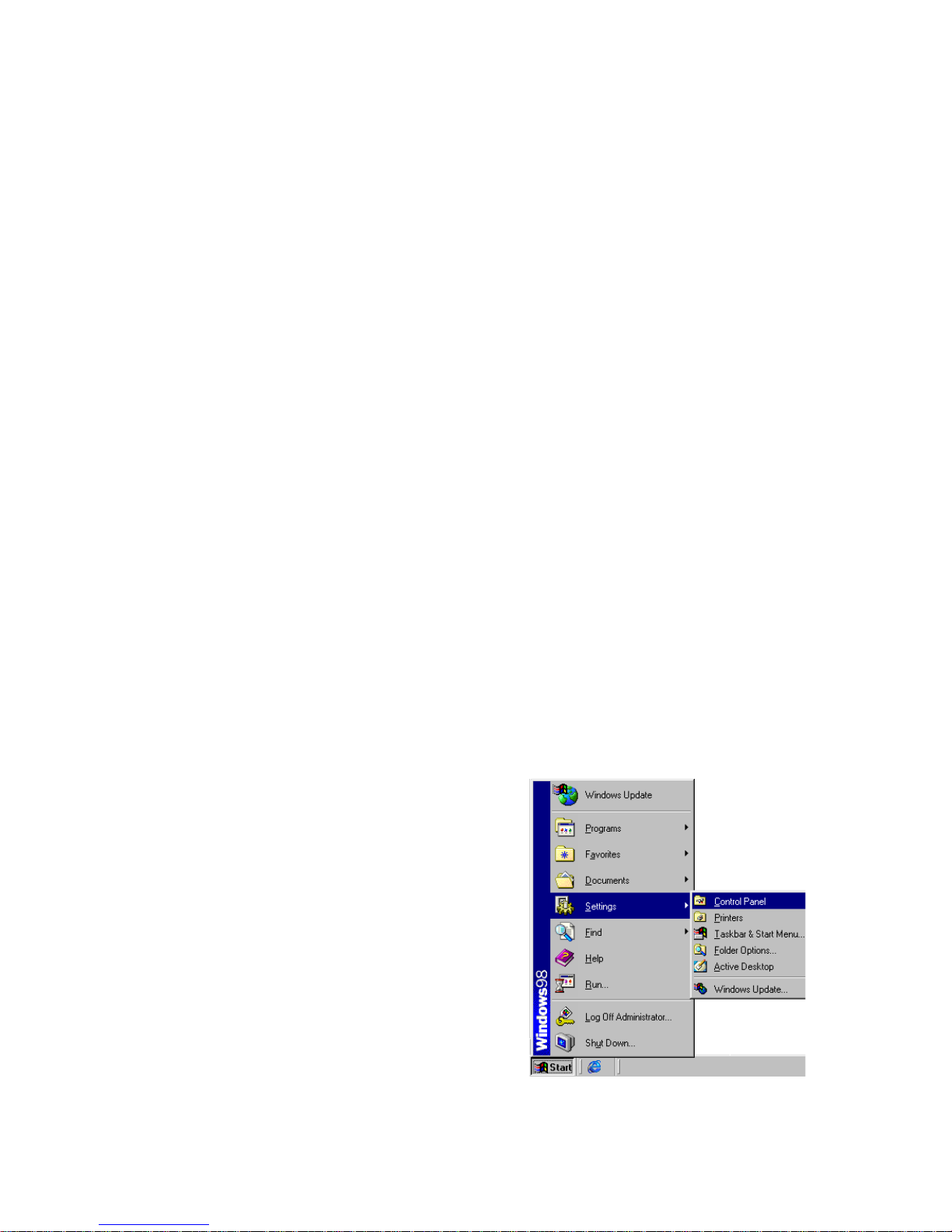
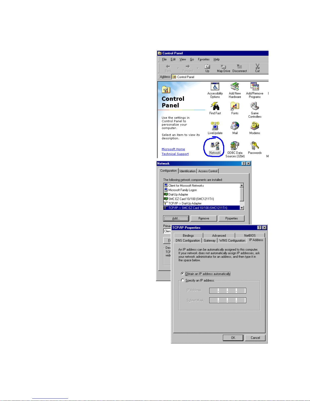
1. On the Windows desktop,
click Start/Settings/Control
Panel.
W
INDOWS
98/M
E
3-3
2. In Control Panel,
double-click the Network
icon.
3. In the Network window,
under the Configuration
tab, double-click the TCP/
IP item listed for your
network card.
4. In the TCP/IP window,
select the IP Address tab. If
“Obtain an IP address
automatically” is already
selected, your computer is
already configured for
DHCP. If not, select this
option.
C
ONFIGURING CLIENT
PC
3-4
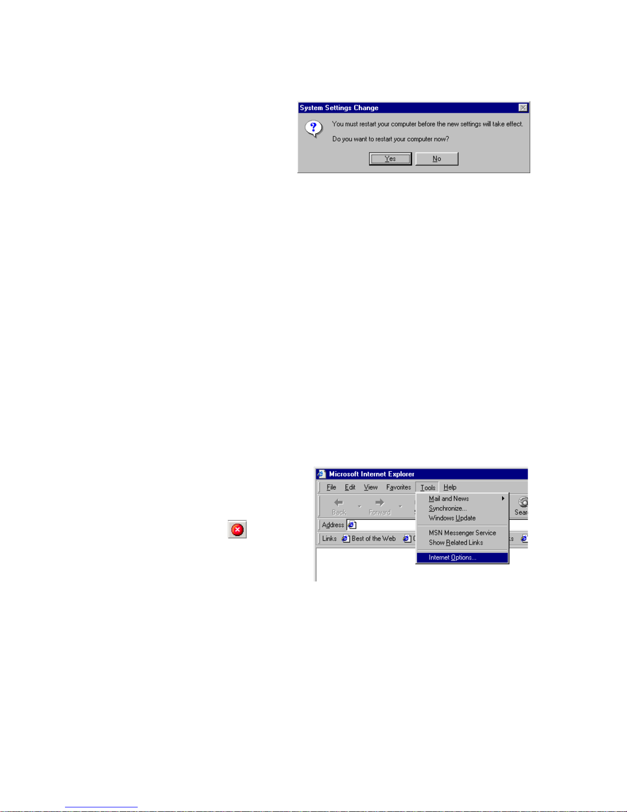
5. Windows may need your
Windows 98/Me CD to
copy some files. After it
finishes copying, it will
prompt you to restart
your system. Click Yes and your computer will restart.
Record the configured information in the following table.
Disable HTTP Proxy
You need to verify that the “HTTP Proxy” feature of your web browser is
disabled. This is so that your browser can view the Barricade’s HTML
configuration pages. The following steps are for Internet Explorer.
Internet Explorer
1. Open Internet Explorer.
2. Click the Stop button,
then click Tools/Internet
Options.
TCP/IP Configuration Setting
Primary DNS Server ____.____.____.____
Secondary DNS Server ____.____.____.____
Default Gateway ____.____.____.____
Host Name ____.____.____.____
 Loading...