

Page 1
S0700-TFS56
Instruction Manual
Manifold 56-SS0750-##SDA#
Solenoid Valve 56-S07#0#-5-#
The intended use of this manifold is to control pneumatically operated
equipment in ATEX Zone 2 (3G) areas. The valves in the manifold are
controlled via the 56-EX260 Serial Transmission System.
This manual should be read in conjunction with the manual for the 56EX260 (56-EX260-TFT07).
1 Safety Instructions
These safety instructions are intended to prevent hazardous situations
and/or equipment damage. These instructions indicate the level of potential
hazard with the labels of “Caution,” “Warning” or “Danger.”
They are all important notes for safety and must be followed in addition to
International Standards (ISO/IEC)
1)
, and other safety regulations.
1)
ISO 4414: Pneumatic fluid power - - General rules relating to systems.
ISO 4413: Hydraulic fluid power - - General rules relating to systems.
IEC 60204-1: Safety of machinery - -Electrical equipment of machines.
(Part 1: General requirements)
ISO 10218-1: Manipulating industrial robots -Safety.etc.
This manual contains essential information for the protection of users and
others from possible injury and/or equipment damage.
1 Safety Instructions (continued)
Read this manual before using the product, to ensure correct handling,
and read the manuals of related apparatus before use.
Keep this manual in a safe place for future reference.
To ensure safety of personnel and equipment the safety instructions in
this manual must be observed, along with other relevant safety
practices.
Caution
Caution indicates a hazard with a low level of risk
which, if not avoided, could result in minor or
moderate injury.
Warning
Warning indicates a hazard with a medium level
of risk which, if not avoided, could result in death
or serious injury.
Danger
Danger indicates a hazard with a high level of risk
which, if not avoided, will result in death or serious
injury.
1.1 Safety instructions
Warning
The compatibility of the product is the responsibility of the person
who designs the equipment or decides its specifications.
Since the product specified here is used under various operating
conditions, its compatibility with specific equipment must be decided by
the person who designs the equipment or decides its specifications
based on necessary analysis and test results. The expected
performance and safety assurance of the equipment will be the
responsibility of the person who has determined its compatibility with the
product. This person should also continuously review all specifications of
the product referring to its latest catalogue information, with a view to
giving due consideration to any possibility of equipment failure when
configuring the equipment.
Only personnel with appropriate training should operate machinery
and equipment.
The product specified here may become unsafe if handled incorrectly.
The assembly, operation and maintenance of machines or equipment
including our products must be performed by an operator who is
appropriately trained and experienced.
Do not service or attempt to remove product and
machinery/equipment until safety is confirmed.
1) The inspection and maintenance of machinery/equipment should only
be performed after measures to prevent falling or runaway of the driven
objects have been confirmed.
2) When the product is to be removed, confirm that the safety measures
as mentioned above are implemented and the power from any
appropriate source is cut, and read and understand the specific product
precautions of all relevant products carefully.
3) Before machinery/equipment is restarted, take measures to prevent
unexpected operation and malfunction.
Contact SMC beforehand and take special consideration of safety
measures if the product is to be used in any of the following
conditions.
1) Conditions and environments outside of the given specifications, or
use outdoors or in a place exposed to direct sunlight.
2) Installation on equipment in conjunction with atomic energy, railways,
air navigation, space, shipping, vehicles, military, medical treatment,
combustions and recreation, or equipment in contact with food and
beverages, emergency stop circuits, clutch and brake circuits in press
applications, safety equipment or other applications unsuitable for the
standard specification described in the product catalogue.
3) An application which could have negative effects on people, property,
or animals requiring special safety analysis.
4) Use in an interlock circuit, which requires the provision of double
interlock for possible failure by using a mechanical protective function,
and periodical checks to confirm proper operation.
Always ensure compliance with relevant safety laws and standards.
All electrical work must be carried out in a safe manner by a qualified
person in compliance with applicable national regulations.
1 Safety Instructions (continued)
1.2 Special conditions of use
Warning
Protect from impacts using an ATEX compliant enclosure.
Do not separate manifold components when energised.
The manifold is suitable for use in ATEX Zone 2 applications only.
Ensure that the hazardous gas does not enter the pneumatic circuit.
The manifold must be installed in an enclosure of at least IP54.
The manifold is suitable for areas of maximum pollution degree 2 only.
To maintain the IP rating, do not separate manifold parts.
To avoid static charge build up, use only a damp cloth to clean the
manifold.
Ensure that the product does not become electrostatically charged.
Protect the unit from sources of heat which can generate surface
temperatures higher than the temperature classification.
Use only ATEX approved M12 connectors and use only shielded
cable to provide grounding.
Only 56-S07#0#-5-# valves to be used in this manifold.
If energising 5 or more adjacent stations for an extended period the ON
time must be less than the OFF time in any 24 hour period.
Caution
Ensure that the air supply system is filtered to 5 microns.
The product is provided for use in manufacturing industries.
The product herein described is basically provided for peaceful use in
manufacturing industries.
If considering using the product in other industries, consult SMC
beforehand and exchange specifications or a contract if necessary.
If anything is unclear, contact your nearest sales branch.
1.3 Conformity to Standards
This product conforms to the following ATEX standards
Electrical Apparatus for Explosive
Gas Atmospheres
EN 60079-0:2012+A11:2013
EN 60079-15:2010
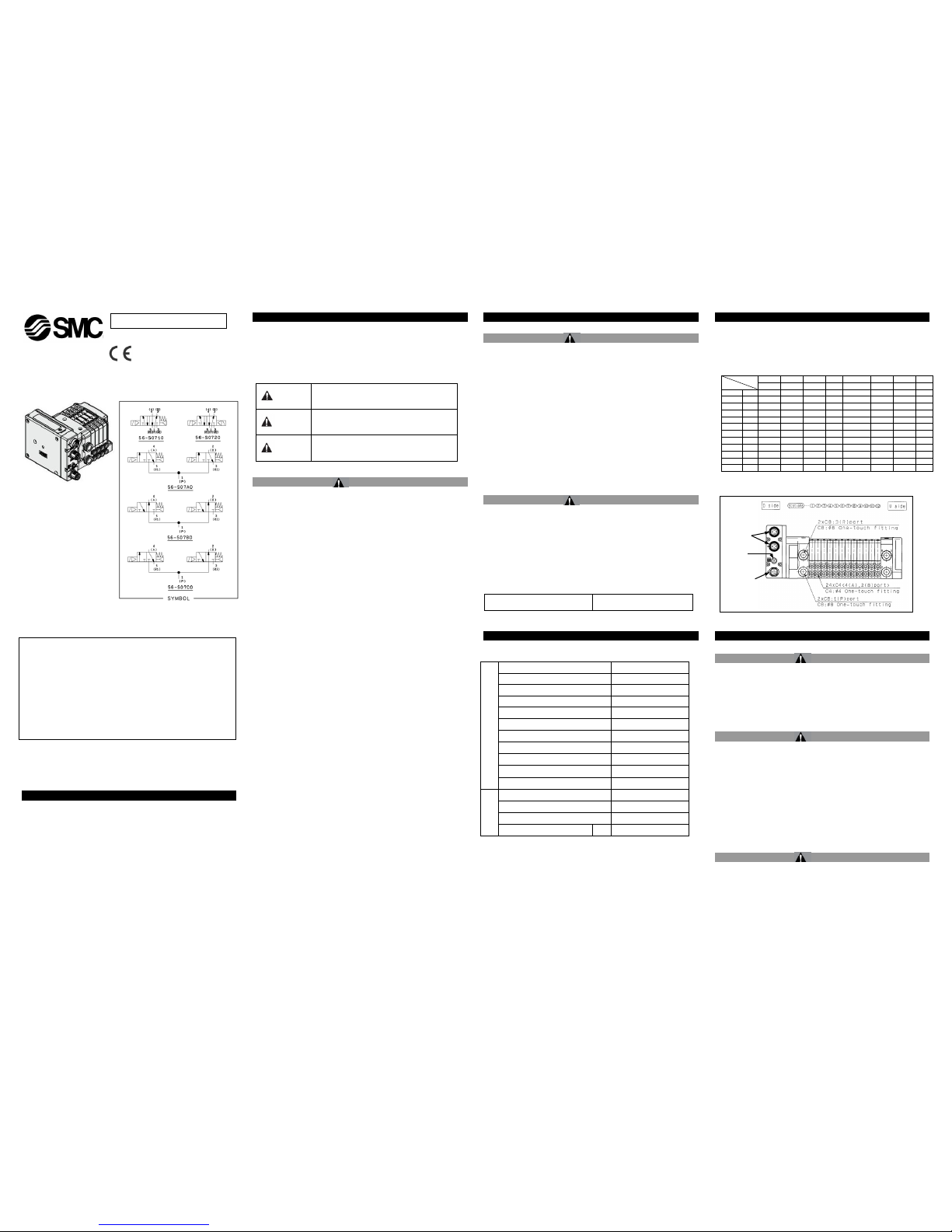
2 Specifications
2.1 General specifications
56-S07#0#-5-# Solenoid valve
Valve specification
Valve construction
Rubber seal
Fluid
Air/Inert gas
Maximum operating pressure
0.7MPa [1.0MPa]
Minimum operating pressure
0.2MPa [0.3MPa]
Ambient temperature °C
–10 to 50°C
(Note 1)
Maximum operating frequency
5Hz
Pilot valve exhaust method
Common exhaust
Pilot valve manual override
Push type
Lubrication
Not required
Impact/Vibration resistance
(Note 2)
30/100 m/s2
Enclosure
See notes 3, 4
Electrical
specification
Coil rated voltage
24 VDC
Allowable voltage variation
±10% of rated voltage
Coil insulation type
Class B or equivalent
Power consumption (current)
DC
0.35W [0.5W]
Value in [ ] shown for K option
Note 1) Use dry air to prevent condensation when operating at low
temperatures.
Note 2) Impact resistance: No malfunction occurred when it is tested
with a drop tested in the axial direction and at right angles to the main
valve and armature in both energised and de-energised states.
Vibration resistance: No malfunction occurred in a one-sweep
test between 8.3 and 2000 Hz. Test was performed in both energised and
de-energised states in the axial direction and at right angles to the main
valve and armature.
2 Specifications (continued)
Note 3) The manifold must be installed in an enclosure of at least IP54,
and only used in an area of maximum pollution degree 2.
Note 4) Protect from impacts using an ATEX compliant enclosure.
Note 5) For 56-EX260 specifications, see manual 56-EX260-TFT07.
2.2 Batch codes and construction month:
2.3 Piping
56-SS0750-##SDA# (56-EX260)
3 Installation
3.1 Installation
Warning
Do not install the product unless the safety instructions in section 1 have
been read and understood.
Protect from impacts using an ATEX compliant enclosure.
To maintain the IP rating, do not separate manifold parts.
This manual should be read in conjunction with the manual for the 56-
EX260 (56-EX260-TFT07).
3.2 Environment
Warning
Do not use in an environment where corrosive gases, chemicals, salt
water or steam are present.
Do not expose to direct sunlight. Use a suitable protective cover.
Do not install in a location subject to vibration or impact. Check the
product specifications.
Do not mount in a location exposed to radiant heat.
The manifold is suitable for use in ATEX Zone 2 applications only.
Ensure that the hazardous gas does not enter the pneumatic circuit.
The manifold must be installed in an enclosure of at least IP54.
The manifold is suitable for areas of maximum pollution degree 2 only.
Ensure that the product does not become electrostatically charged.
3.3 Lubrication
Caution
SMC products have been lubricated for life at manufacture, and do not
require lubrication in service.
If a lubricant is used in the system, use turbine oil Class 1 (no additive),
ISO VG32. Once lubricant is used in the system, lubrication must be
continued because the original lubricant applied during manufacturing
will be washed away.
Contact SMC for OIL FREE specification.
Year
Month
2012
2013
2014
….
2021
2022
2033
…. Q R S …. Z A B ….
Jan O Qo
Ro
So
….
Zo
Ao
Bo
….
Feb P QP
RP
SP
….
ZP
AP
BP
….
Mar Q QQ
RQ
SQ
….
ZQ
AQ
BQ
….
Apr R QR
RR
SR
….
ZR
AR
BR
….
May S QS
RS
SS
….
ZS
AS
BS
….
Jun T QT
RT
ST
….
ZT
AT
BT
….
Jul U QU
RU
SU
….
ZU
AU
BU
….
Aug V QV
RV
SV
….
ZV
AV
BV
….
Sep W QW
RW
SW
….
ZW
AW
BW
….
Oct X QX X SX
….
ZX
AX
BX
….
Nov Y Qy
RQy
Sy
….
Zy
Ay
By
….
Dec Z QZ
RZ
SZ
….
ZZ
AZ
BZ
….
ORIGINAL INSTRUCTIONS
Refer to Declaration of
Conformity for relevant
Directives
ATEX Marking Description
II 3G Ex nA IIC T3 Gc X Ta -10 to 50°C
Equipment Group II
Category 3
Gas (G) environment
Ex European standards apply
nA Non- sparking apparatus
IIC For all types of gas
T3 Temperature classification
Gc Equipment Protection Level (EPL)
X Special conditions apply, see section 1.2
Ta Ambient temperature range
Communication
(M12)
Power (M12)
Ground
terminal
Page 1 of 2
Page 2
S0700-TFS56
4 Settings
4.1 Manual override
Warning
The manual override is used for switching the main valve.
Push style (tool needed)
Push down on the manual override button with a small screwdriver until it
stops.
4.2 56-EX260-###-X## Serial Transmission System
For 56-EX260 specifications, see manual 56-EX260-TFT07.
5 How to Order
Contact SMC for relevant assembly drawing.
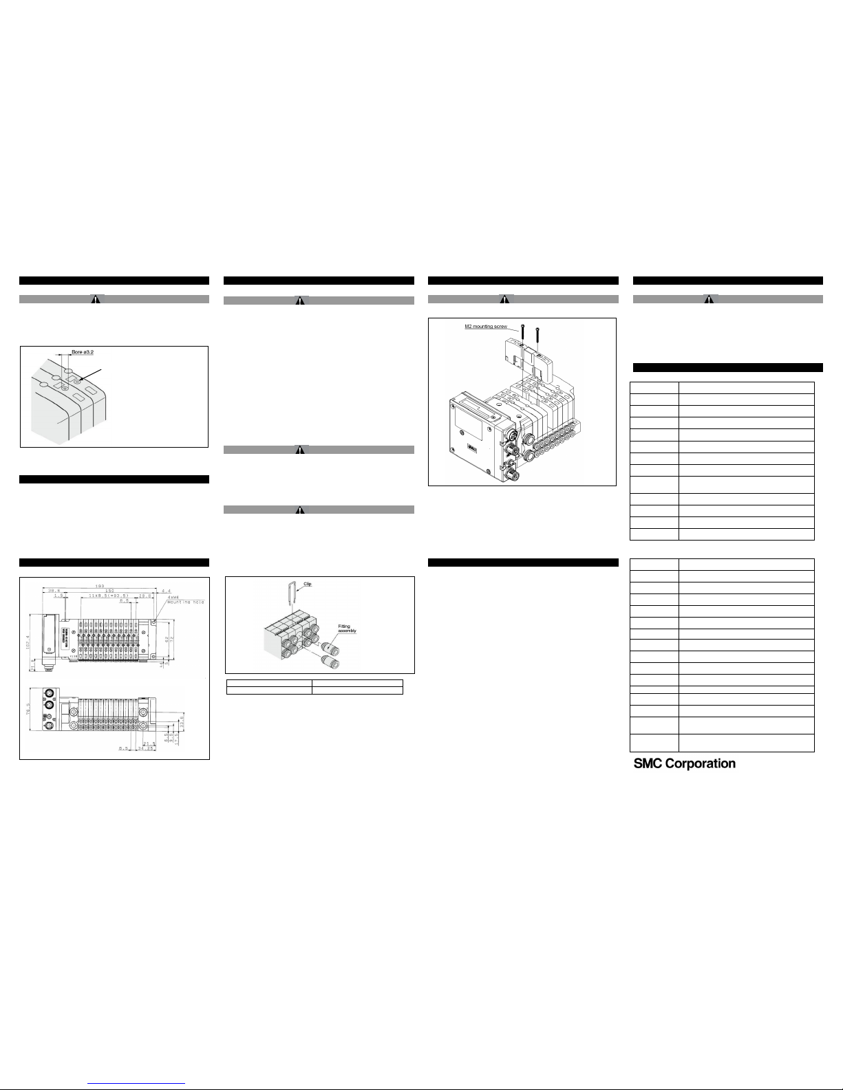
6 Outline Dimensions (mm)
56-SS0750-##SDA# (Dimensions shown for a 12 station manifold)
7 Maintenance
7.1 General Maintenance
Caution
Not following proper maintenance procedures could cause the product to
malfunction and lead to equipment damage.
If handled improperly, compressed air can be dangerous. Maintenance
of pneumatic systems should be performed only by qualified personnel.
Before performing maintenance, turn off the power supply and be sure to
cut off the supply pressure. Confirm that the air is released to
atmosphere.
After installation and maintenance, apply operating pressure and power
to the equipment and perform appropriate functional and leakage tests to
make sure the equipment is installed correctly.
If any electrical connections are disturbed during maintenance, ensure
they are reconnected correctly and safety checks are carried out as
required to ensure continued compliance with applicable national
regulations.
Do not make any modification to the product.
Do not disassemble the product, unless required by installation or
maintenance instructions.
7.2 Safety
Warning
Ensure that the Safety Instructions in section 1 of this document have
been read and understood before carrying out maintenance procedures.
Do not separate manifold components when energised.
To avoid static charge build up, use only a damp cloth to clean the
manifold.
7.3 Replacing the A/B port one-touch fittings
Warning
The A/B port fittings are cassette type so they can be easily replaced. The
fittings are held in place by a clip inserted from the top of the manifold, so
this clip should be removed with a flat bladed screwdriver before replacing
the fittings.
To replace, after inserting the fitting assembly into position, replace the clip
in its correct position.
This part number is for one fitting assembly.
Please order in units of 10.
7Maintenance (continued)
7.3 Mounting of valves
Warning
Valve mounting method
Tighten mounting screws to a torque of 0.17–0.23 N.m to clamp the gasket
securely.
8 Limitations of Use
8.1 Limited warranty and Disclaimer/Compliance Requirements
The product used is subject to the following “Limited warranty and
Disclaimer” and “Compliance Requirements”. Read and accept
them before using the product.
Limited warranty and Disclaimer
1) The warranty period of the product is 1 year in service or 1.5 years
after the product is delivered, whichever is first
(1)
. Also, the product may
have specified durability, running distance or replacement parts. Please
consult your nearest sales branch.
2) For any failure or damage reported within the warranty period which is
clearly our responsibility, a replacement product or necessary parts will
be provided.
This limited warranty applies only to our product independently, and not
to any other damage incurred due to the failure of the product.
3) Prior to using SMC products, please read and understand the
warranty terms and disclaimers noted in the specified catalogue for the
particular products.
(1)
Vacuum pads are excluded from this 1 year warranty.
A vacuum pad is a consumable part, so it is warranted for a year after it
is delivered. Also, even within the warranty period, the wear of a product
due to the use of the vacuum pad or failure due to the deterioration of
rubber material are not covered by the limited warranty.
Compliance Requirements
1) The use of SMC products with production equipment for the
manufacture of weapons of mass destruction (WMD) or any other
weapon is strictly prohibited.
2) The exports of SMC products or technology from one country to
another are governed by the relevant security laws and regulations of
the countries involved in the transaction. Prior to the shipment of a SMC
product to another country, assure that all local rules governing that
export are known and followed.
8Limitations of use (continued)
Caution
SMC products are not intended for use as instruments for legal
metrology.
Measurement instruments that SMC manufactures or sells have not
been qualified by type approval tests relevant to the metrology
(measurement) laws of each country.
Therefore, SMC products cannot be used for business or certification
ordained by the metrology (measurement) laws of each country.
9 Contacts
AUSTRIA
SMC PneumatikGmbH,Girakstrasse 8, AT-2100
Korneuburg, Austria
BELGIUM
SMC Pneumatics N.V. ⁄ S.A. Nijverheidsstraat 20, B-2160
Wommelgem, Belgium
BULGARIA
SMC Industrial Automation Bulgaria EOOD, Business
Park Sofia, Building 8-6th floor, BG-1715 Sofia, Bulgaria
CROATIA
SMC IndustrijskaAutomatikad.o.o. ZagrebačkaAvenija
104,10 000 Zagreb
CZECH REP.
SMC Industrial Automation CZ s.r.o. Hudcova 78a, CZ61200 Brno, Czech Republic
DENMARK
SMC Pneumatik A ⁄ S,Egeskovvej 1, DK-8700 Horsens,
Denmark
ESTONIA
SMC Pneumatics Estonia Oü,Laki 12, EE-10621 Tallinn,
Estonia
FINLAND
SMC Pneumatics Finland Oy, PL72, Tiistinniityntie 4, SF02031 Espoo, Finland
FRANCE
SMC Pneumatique SA.1, Boulevard de Strasbourg,
ParcGustave Eiffel, Bussy Saint Georges, F-77607 Marne
La ValleeCedex 3, France
GERMANY
SMC Pneumatik GmbH, Boschring 13-15, 63329
Egelsbach, Germany
GREECE
SMC Italia Hellas Branch, Anagenniseos 7-9-P.C. 14342
N.Philadelphia, Athens, Greece
HUNGARY
SMC Hungary IpariAutomatizálásiKft.Torbágy u. 19, HU2045 Törökbálint, Hungary
IRELAND
SMC Pneumatics (Ireland) Ltd.2002 Citywest Business
Campus, Naas Road, Saggart, Co. Dublin, Ireland
ITALY
SMC Italia S.p.A.Via Garibaldi 62, I-20061Carugate,
(Milano), Italy
LATVIA
SMC Pneumatics Latvia SIA, Dzelzavas str. 120g, Riga,
LV-1021, Latvia
LITHUANIA
UAB “SMC Pneumatics”, Oslo g. 1, LT-04123 Vilnius,
Lithuania
NETHERLANDS
SMC Pneumatics B.V.DeRuyterkade 120, NL-1011 AB
Amsterdam, the Netherlands
NORWAY
SMC Pneumatics Norway AS, Vollsveien 13 C,
GranfosNæringspark, N-1366 Lysaker, Norway
POLAND
SMC Industrial Automation Polska Sp. z o.o.ul.
Konstruktorska 11A, PL-02-673 Warszawa, Poland
PORTUGAL
SMC España S.A. Zuazobidea 14, 01015 Vitoria, Spain
ROMANIA
SMC Romania S.r.l. StrFrunzei 29, Sector 2, Bucharest,
Romania
RUSSIA
SMC Pneumatik LLC. Business centre, building 3, 15
Kondratjevskij prospect, St.Petersburg, Russia, 195197
SLOVAKIA
SMC PriemyselnáAutomatizáciaSpols.r.o. Fantranská
1223, Teplickanadvahom, 01301, Slovakia
SLOVENIA
SMC IndustrijskaAvtomatikad.o.o. Mirnskacesta 7, SLO8210 Trebnje, Slovenia
SPAIN
SMC España S.A. Zuazobidea 14, 01015 Vitoria, Spain
SWEDEN
SMC Pneumatics Sweden AB,Ekhagsvägen 29-31, SE141 71 Segeltorp, Sweden
SWITZERLAND
SMC PneumatikAG,Dorfstrasse 7, Postfach, 8484
Weisslingen, Switzerland
TURKEY
SMC PnömatikSanayiTicaretveServis A.Ş.
GülbaharCaddesi, Aydın Plaza, No: 9 ⁄ 4 Güneşli –
34212 , Istanbul
UK
SMC Pneumatics (U.K.) Ltd. Vincent Avenue, Crownhill,
Milton Keynes, Buckinghamshire MK8 0AN, United
Kingdom
URL :
http// www.smcworld.com (Global) http// www.smceu.com (Europe)
'SMC Corporation, Akihabara UDX15F, 4-14-1, Sotokanda, Chiyoda-ku, Tokyo 101
0021
Specifications are subject to change without prior notice from the manufacturer.
© 2015 SMC Corporation All Rights Reserved.DKP50047-F-085B Feb. 2015
Tube diameter
One-touch fitting part number
Applicable tube ø4
VVQ0000-50A-C4
Manual override button
Page 2of 2
 Loading...