

Page 1

EZ Connect™
Wireless Print Server
User Guide
SMC2622W-P
SMC2622W-U
Page 2

Table of Contents
Chapter 1 Introduction: page 3
Features
Package Contents
Models
LED indicators
Diagnostic Push Button
Chapter 2 LAN Installation: page 8
Chapter 3 Print Server Configuration: page 10
Overview
Using the Windows Wizard
Alternatives to the Windows Wizard
Wireless Configuration
Advanced Configuration and Management
Chapter 4 Client PC Configuration: page 18
Overview
Windows Peer-to-Peer Print Driver
Windows SMB Printing
Windows with Server-based Print Queues
Macintosh (AppleTalk)
Chapter 5 BiAdmin Management Utility: page 29
Requirements
Installation
Operation
Chapter 6 Web Interface Setup: page 37
Overview
Preparation
Connecting to the Print Server
Configuration Screens
Chapter 7 Special Features: page 47
Overview
Internet Printing Protocol (IPP)
Internet Mail Printing
SNMP
English
1
Page 3

Chapter 8 Troubleshooting: page 62
Overview
Hardware & LAN Problems
AppleTalk (Macintosh)
Windows Printing Problems
Appendix A Specifications: page 71
General Specifications
Regulatory Approvals
Safety Instructions
Appendix B Wireless PCMCIA Adapter Installation: page 74
Appendix C Network Server Configuration: page 77
Windows NT Server
Windows 2000 Server
Unix Systems
Contact SMC & Warranty Information
English
2
Page 4

English
Chapter 1: Introduction
Features
Congratulations on the purchase of your new Print Server. This
device was designed to provide a simple and efficient network
printing solution. It is packed with features, including:
• Versatility. The Print Server supports TCP/IP, SMB (Service
Message Block), AppleTalk (EtherTalk), and NetBEUI. Operating
system support includes Apple, Unix, and Microsoft Windows.
• Easy Installation and Setup. Installation can be
accomplished in minutes. For initial configuration, a number
of utility programs are supplied to simplify setup. For
Windows 95/98/NT/ME/2000/XP users, the supplied Wizard
allows quick and easy setup.
• Web-based Interface. The Web-based interface provides an
easy method of configuration in TCP/IP networks.
• Compact Size. This allows the Print Server to be used even
where space is limited.
• Remote Management Tools. A variety of software tools are
provided. In most environments, both the Print Server and
attached bi-directional printers can be configured remotely,
from any station on your LAN. For Windows users, the
supplied BiAdmin program makes it easy to configure the Print
Server for a variety of network and server configurations
• SNMP Support. The Print Server can act as a SNMP agent,
with it's own MIB. This allows TCP/IP users to monitor,
configure and troubleshoot the Print Server using their
existing SNMP management tools.
• JetAdmin Support. If you are already using HP's JetAdmin,
you can also use this program to manage your Print Server.
3
Page 5

•Internet Printing Protocol (IPP) Support. All models can
act as an IPP (Internet Printing Protocol) Server, allowing
clients, suppliers, colleagues and others to print to your
printer from anywhere on the Internet. Windows IPP Client
software is also supplied.
• Wireless LAN Support. Wireless stations supporting the IEEE
802.11b standard can interoperate with the Wireless Print Server.
Both LAN and WLAN users can print to the attached printer.
Package Contents
You should find the following items packaged with your
Print Server:
• Power Adapter
• Quick Installation Guide
• CD-ROM containing all support programs and this manual in
English. Manuals in German and French language are available
for download on www.smc-europe.com (support).
If any items are missing, contact your dealer immediately.
Models
This manual covers the following Wireless Print Server models.
Further details of each model are contained in Appendix
A - Specifications.
English
4
Page 6
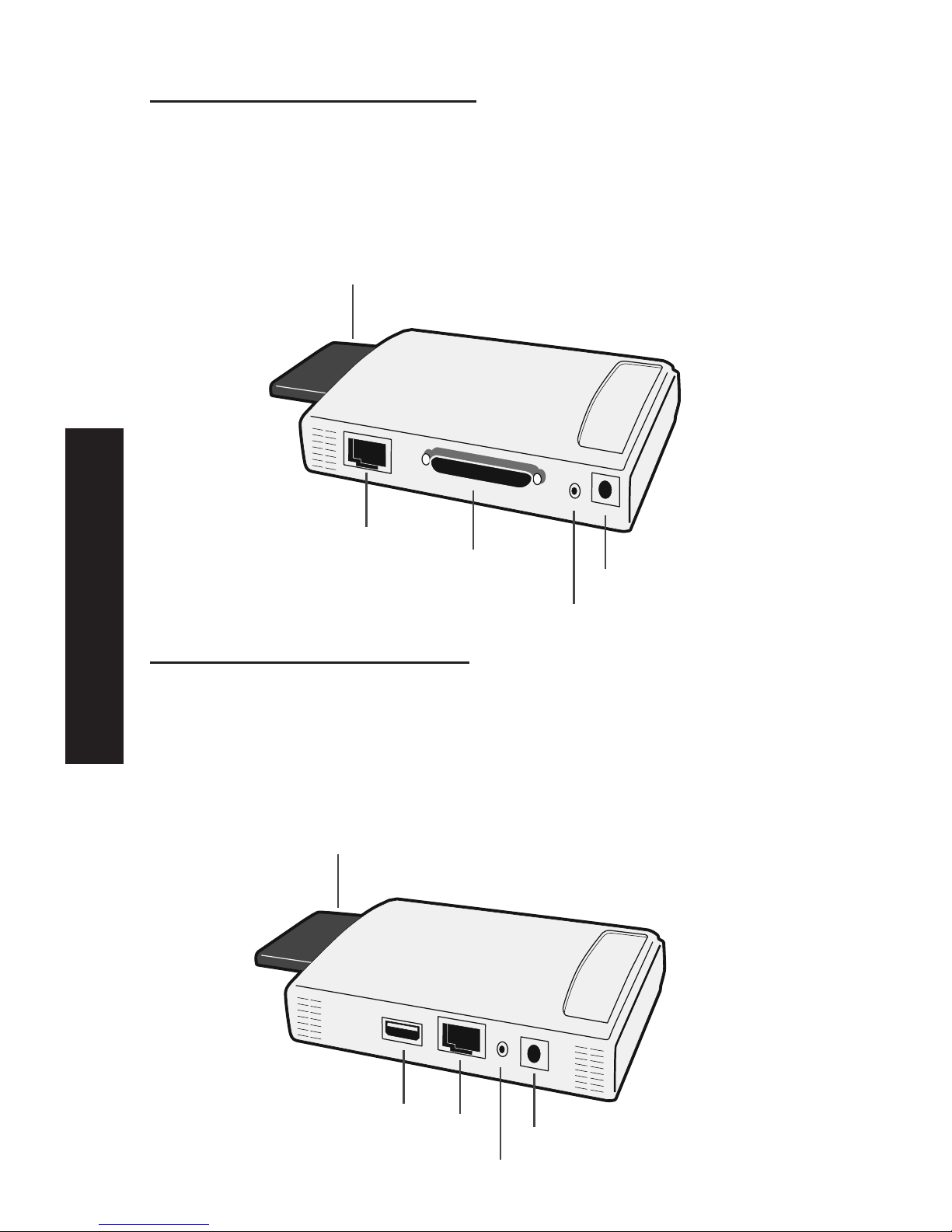
SMC2622W-P Print Server
• 1 Parallel Printer Port
• IEEE 802.11b Wireless PC Card Slot
• 10/100BASE-T LAN connection
SMC2622W-U Print Server
• 1 USB Printer Port
• IEEE 802.11b Wireless PC Card Slot
• 10/100BASE-T LAN connection
USB
Port
LAN
Port
Power
Diagnostic
Button
PCMCIA
Wireless
Card
LAN
Port
Power
Diagnostic
Button
Parallel
Port
PCMCIA
Wireless
Card
English
5
Page 7

LED Indicators
On the Print Servers two LED indicators can be found on the
top. The "Error" LED is orange or red. The "Status" indicator LED
is green. The LED indicator modes are described in the following
table.
Status Error Description
Solid Off Solid Off No powers
Solid On Solid On Hardware Error
Solid On Solid Off Normal operation (Idle)
Blinking Blinking Firmware upgrade in progress
(the two LED blink in sequence)
The LED indicators on the SMC2622W-P and SMC2622W-U
describe the following:
LED Description
WLAN Act Off - Idle
Flashing - Transmitting or receiving data through Wireless LAN
LAN Act Off - Idle
Flashing - Transmitting or receiving dtat through the LAN.
Diagnostic Push Button
The Print Servers are fitted with a Diagnostic Push Button. The
button is recessed; a pin or paper clip can be used to press it.
This button has 2 functions:
• Restore the factory default settings
• Print a test page containing all current settings
To restore the factory default settings:
1. Turn the Print Server OFF.
English
6
Page 8

2. Press and hold the diagnostic button. While pressing the
button, switch the Print Server ON.
3. If you continue pressing the button for 10 seconds, a
diagnostic page will be printed, showing the new (default)
settings.
To generate a Diagnostic print out
1. Ensure that both the Print Server and the attached printer are
ON.
2. Press the diagnostic button, and hold it in for 2 seconds.
3. The test page, containing the current settings, will be printed.
Note:
PostScript printers are unable to print this page. If you have a
PostScript printer, the test page will not be printed.
English
7
Page 9

Chapter 2: LAN Installation
Procedure
A.Preparation
1. Ensure the power is OFF. Do not connect the Print Server
while power is on.
a) For those using the Wireless PCMCIA adapter SMC2632W V.2
please follow the installation instruction:
Insert your Wireless card SMC2632W V.2 into the PCMCIA slot on
the Print Server until it encounters some resistance. Push firmly
and it will click into position.
If you are using a different wireless adapter of a different
provider, please refer to Appendix B in this full installation
guide.
b) If you don't use a wireless connection, continue with the
described installation below for wired LAN connection.
B.Connect the Printer or Printers
• Connect the printer or plotter cable(s) to the appropriate
port(s) on the Print Server unit. Parallel port cables should be
less than 3 meters long.
C. Connect the Network Cable
• Connect a standard network cable from the LAN connector on
the Print Server to a 10BASE-T or 100BASE-TX hub or switch.
NOTE: On the SMC2622W-P and SMC2622W-U, this will disable
the Wireless interface, because the default "Infrastructure
mode" wireless setting cannot be used with the LAN interface.
To use both the LAN and Wireless interfaces, the Wireless
mode must be set to "Ad-hoc". After configuration, the LAN
interface can be disconnected if not required.
English
8
!
!
Page 10

English
D.Power Up and Check the LEDs
• Plug in the power adapter cable and power up. Start-up will
take only a few seconds.
• Check the Power and Status LED indicators of the unit. When
the red Error LED goes out and the green Status LED remains
lit or flashes, the Print Server is ready.
WARNING: Use only the Power Supply unit provided with the
device. Power Supply units for different models are not
interchangeable.
9
Page 11

English
Chapter 3: Print Server Configuration
Overview
The Print Server is designed to support many different platforms,
and the configuration required would depend upon the
environment in which it is installed.
• The Print Server usually requires configuration. A Windows-based
setup Wizard is provided on the CD-ROM to simplify this task.
• PCs wishing to use the printer attached to the Print Server
always require configuration. See chapter "Client Configuration"
for details.
• If you wish to use a queue-based printing system using
Windows NT Server/Windows 2000, the Network Server must be
configured as detailed in Appendix C - Network Server
Configuration. However, it is not necessary to use a Network
Server-based queue; client PCs can print directly to the Print
Server using the Peer-to-peer Print Driver installed by the User
setup option on the CD-ROM.
NOTE: SMC2622W-P and SMC2622W-U models support Windows,
Linux, Unix and Macintosh environments only.
Using the Windows Wizard
The Windows-based Wizard runs on Windows 95, 98, NT4.0, ME,
Windows 2000 and XP.
It will configure the Print Server for your Network environment.
Procedure
1. Insert the supplied CD-ROM into your drive. If the setup
program does not start automatically, run SETUP in the root
folder.
2. Run the Setup Wizard, either by using this option on the first
installation screen, or by selecting it from the menu after
running the Installation option.
10
Page 12

English
NOTE: Select the Administrator option when running the
Installation. This will install both the Setup Wizard and the
BiAdmin management program.
3. Within the Setup Wizard, select the Print Server you wish to
configure, click Next, and step through the Wizard.
If the desired Print Server is not listed:
• Check all cables to the Print Server.
• Check the Print Server's LEDs:
• The red LED should be OFF and the green LED should be ON or
flashing.
• If your model supports 10BASE-T and 100BASE-T, check the
10/100BASE-T link LED next to the LAN connection. If the
auto negotiation fails, the 10/100BASE-T Link LED will not
light when the device is powered up. If there are 2 LEDs,
neither will light.
• Check that your PC and the Print Server are on the same LAN
segment. If you don't have a Router or Gateway on your LAN,
you only have 1 segment.
• Check that your PC has either the TCP/IP or NetBEUI network
protocols installed. See "Checking your Network Protocols" in
the chapter "Client PC Configuration" for details.
• If you PC can't configure the Print Server correctly (in
Infrastructure mode), then try to connect to LAN and disable the
Wireless.
Alternatives to the Windows Wizard
If you do not have a Windows 32bit platform available, use one
of the following methods to configure the Print Server.
Web Browser See chapter “Web Interface Setup” for details
FTP Using this method, the configuration file is downloaded from
the Print Server, edited, and then sent back. No software needs
to be installed.
See the UNIX manual for details. The Unix manual is on the
CD-ROM, in the Manual\Unix folder.
11
Page 13

English
Wireless Configuration
Models SMC2622W-P and SMC2622W-U
The SMC2622W-P and SMC2622W-U are Wireless stations, not
access points. Like all other Wireless stations, they have 3
modes:
• 802.11 Ad Hoc mode - no Access Point is used, Wireless
stations communicate directly with each other. This is the
current standard.
• Ad Hoc mode - no Access Point is used, Wireless stations
communicate directly with each other. This is the older
standard.
NOTE: Of the two (2) Ad-hoc modes, "802.11 Ad Hoc" mode is
recommended. If your Wireless LAN Card doesn't provide
"802.11 Ad Hoc" mode, try "Ad Hoc" mode on the PC and
"802.11 Ad Hoc" on the SMC2622W-P/SMC2622W-U. If this
fails, select"Ad-hoc" mode on the Print Server.
Infrastructure (Default) - all Wireless stations connect to the
Access Point. This allows connection to both other Wireless
stations and the wired LAN.
NOTE: The SMC2622W-P and SMC2622W-U do NOT allow both a
LAN connection and "Infrastructure" mode.
In "Infrastructure" mode, connecting a LAN cable will
disable the Wireless interface.
To use the LAN interface, "Ad-hoc" mode must be used.
12
Page 14

Required configuration
Ad-hoc Infrastrusture Mode
SSID Must match the other Must match the Access Point.
Wireless stations, unless the
SSID is null or "any".
If its SSID is null or "any", a
Wireless station can join any
Ad-hoc group. But since the
SMC2622W-P and SMC2622W-U
are fixed devices (rather than
roaming), their SSID should
not be null or "any".
It's recommended to assign
value to SSID for SMC2622W-P
and SMC2622W-U.
Channel Should match the other Access Point sets the Channel
Wireless stations. used.
However, when joining an Wireless stations automatically
existing Ad-Hoc group a wireless locate the correct stations.
station must use the Channel in use,
rather than its own Channel.
For a device like the SMC2622W-P
or SMC2622W-U in a fixed location,
it is best to set them to the
Channel providing the least
interference and best performance.
WEP Settings Must match the other Wireless Must match the other Access
Stations Point
Two (2) methods are available to perform the required configuration:
• BiAdmin management utility program - see below for details.
• Web-based setup - see relevant chapter for details.
BiAdmin Wireless Screen
Installation and use of the BiAdmin Windows utility is described
in chapter "BiAdmin Management Utility".
Clicking the Wireless icon, or selecting Configuration - Wireless
on the menu, will display the following screen.
English
13
Page 15
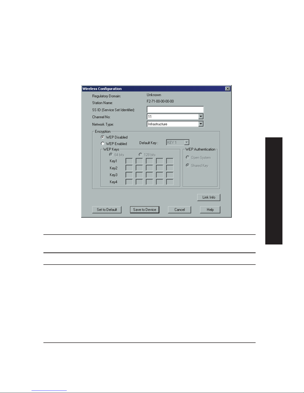
BiAdmin Wireless Screen
Installation and use of the BiAdmin Windows utility is described
in chapter "BiAdmin Management Utility".
Clicking the Wireless icon, or selecting Configuration - Wireless
on the menu, will display the following screen.
Regulatory Domain It is illegal to use this device in any location
outside of the regulatory domain.
Station Name The name used to identify this Wireless station.
SSID • If using an ESS (Extended Service Set, with
multiple access points) this ID is called an
ESSID (Extended Service Set Identifier).
• To communicate, all Wireless stations MUST use
the same SSID/ESSID. Change this value, or
change the other Wireless stations, to ensure
each Wireless station has the same value.
• The default value is "null", so the Wireless
station can join any Ad-hoc group.
Note! The SSID is case sensitive.
Channel No To communicate in "802.11 Ad-hoc" or "Ad hoc"
mode, all Wireless stations MUST use the same
Channel number.
• If using "802.11 Ad-hoc" or "Ad-hoc" mode, select
the value you wish to use on your Wireless LAN.
English
14
Page 16

• If using "Infrastructure" mode, the Channel is
selected automatically, to match the Channel
used by the Access Point.
• If you experience interference (shown by lost
connections and/or slow data transfers) you may
need to experiment with different channels to
see which is the best.
Network Type Select the correct value for your Wireless LAN.
• 802.11 Ad-hoc mode is used when there is no
Wireless Access Point, and each Wireless station
communicates directly with other Wireless
stations. This is the current standard.
• Ad-hoc mode is used when there is no Wireless
Access Point, and each Wireless station
communicates directly with other Wireless
stations. This is the older standard.
• Infrastructure mode is used when each Wireless
station connects to the Wireless Access point.
This also provides access to the wired LAN.
Encryption
WEP Disabled/Enabled If Disabled (default), data is NOT encrypted before
being transmitted.
If Enabled, you must provide either the 64 Bit key
table or the 128 Bit keys, as described below. The
key is used to encrypt the data before
transmission.
64 Bit • If selected, data is encrypted, using the default
key, before being transmitted. The receiving
station must be set to 64 Bit Encryption, and
have the same Key value in the same position in
its key table. Otherwise, it will not be able to
decrypt the data.
• Default Key - select the key you wish to be the
default. Transmitted data is ALWAYS encrypted
using the Default Key; the other Keys are for
decryption only.
Key Table: This table is used when Encrypting
and Decrypting data. All stations, including this
Access Point, always transmit data encrypted
using their default key. The key number (1, 2, 3,
4) is also transmitted. The receiving station will
use the key number (1, 2, 3, 4) to determine
which key value to use for decryption. If the key
value does not match the transmitting station,
English
15
Page 17
decryption will fail.
The easiest way to ensure there are no problems
is to have every Station, including the Access
Point, use the same key table (all entries
identical). Then, it does not matter which key is
used as the default key.
128 Bit If selected, data is encrypted using the key
before being transmitted. The receiving station
must be set to use 128 Bit Encryption, and have
the same Key value. Otherwise, it will not be able
to decrypt the data.
WEP Authentication Options are "Open System" or "Shared Key".
Some Wireless cards and Access Points do not
support both methods. Check your documentation
to determine the correct value to use.
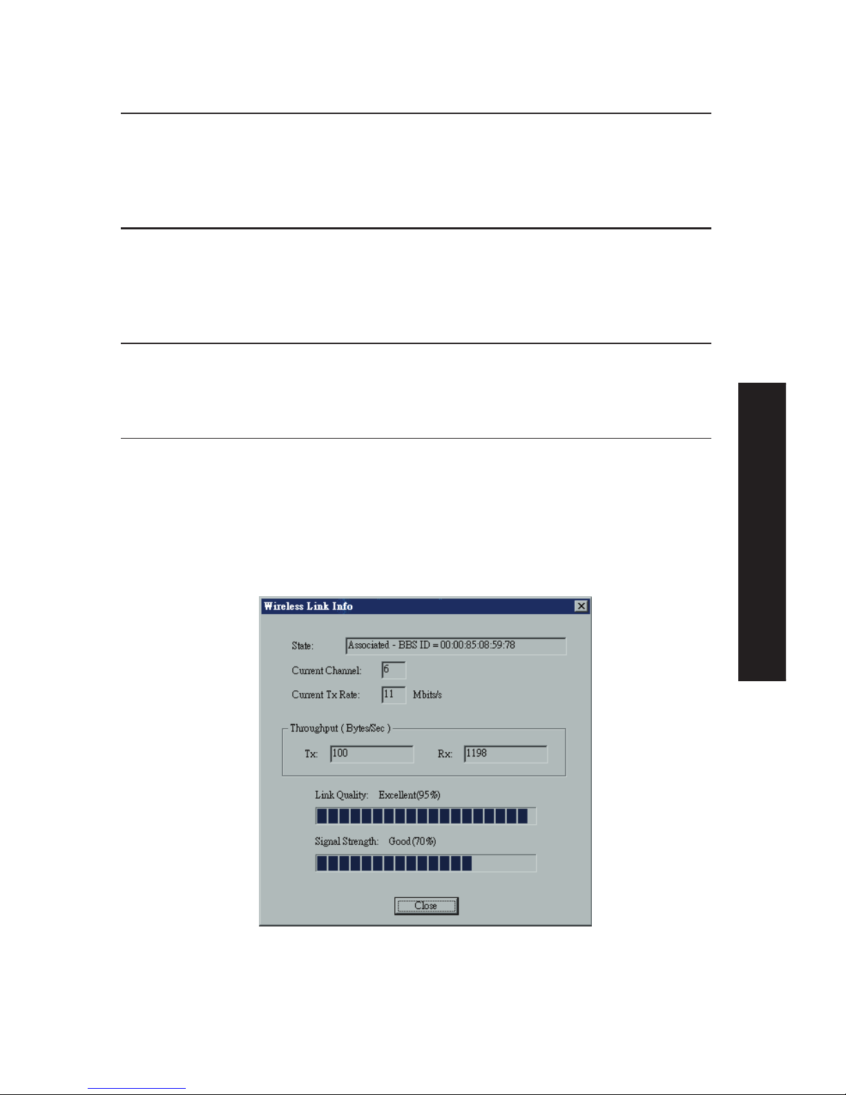
Wireless Link Info Screen
After clicking the "Link Info" button on the Wireless Screen, a
screen like the example below will be shown.
English
16
Page 18

State This indicates which access point is currently in use.
Current Channel The current channel which has been used.
Current TX Rate The current transmitting speed.
Throughput (Tx ) This will show how much data has been transmitted per
second.
Throughput ( Rx ) This will show how much data has been received per second.
Link Quality This indicates the quality of the Wireless connection
Signal Strength This indicates the strength of the Wireless signal being
received.
NOTE: The "Link Quality" and "Signal Strength" data is not
available if using "Ad-hoc" or "802.11 Ad-hoc" mode.
Advanced Configuration and Management
The BiAdmin management utility is provided for advanced
configuration and management. This program is installed by
default when the Administrator install option is chosen. See
chapter "BiAdmin Management Utility" for details on using
BiAdmin.
English
17
Page 19

Chapter 4: Client PC Configuration
Overview
Before performing client configuration, the Print Server must be
installed on your LAN, and configured as described in chapter
"Print Server Configuration". Both the Print Server and the
attached printer must be powered ON.
Printing Methods
The Print Server supports a number of printing methods:
• Peer-to-peer Print Driver is used by the User installation on
the CD-ROM. The print jobs are stored (queued) on your PC,
and sent to the Print Server when it is available.
• Server-based Print Queue means that all print jobs are stored
(queued) on the Network Server (e.g. Windows NT/2000) and
then sent to the Print Server. This allows the Network
Administrator to modify the Print Queue. For example, an
important job can be moved to the head of the queue.
• Windows SMB printing is a Microsoft standard for using a
"Network Printer". No additional software needs to be
installed on your Windows PC, and printing from MS-DOS
programs is supported. However, because the Print Server
can’t store files, large print jobs may cause problems.
• AppleTalk is also supported, and normally no configuration of
the Print Server is required. See the Macintosh section of this
chapter for details of client configuration.
Which printing method should I use?
• If using Windows 95, 98, NT, ME or 2000, the easiest method
is to install the Peer-to-peer Print Driver on the CD-ROM, by
selecting the User installation.
• If using Windows, and you need to print from MS-DOS
programs, or you don't wish to install additional software,
use SMB.
English
18
Page 20
However, SMB is not suitable for large, complex documents, so if
you need this as well as MS-DOS printing, you should install
BOTH the Peer-to-peer Print Driver and SMB printing. MS-DOS
programs can use the SMB printer, Windows programs should use
the Peer-to-peer Print Driver.
• If your LAN has Network Servers (e.g. Windows NT, Windows
2000 Server) use the method advised by your Network
Administrator. The Print Server can print via a queue located
on a Network server, if desired.
• Unix users - refer to the Unix Manual on the CD-ROM, in the
Manual/Unix directory.
• Macintosh users - refer to the Macintosh section of this
chapter.
Checking your Network Protocols (Windows)
Your PC must have either the TCP/IP or NetBEUI protocols
installed.
• If using the Peer-to-peer Print Driver, the installation program
will check this for you.
• If using Windows SMB Printing, you must check manually, as
follows:
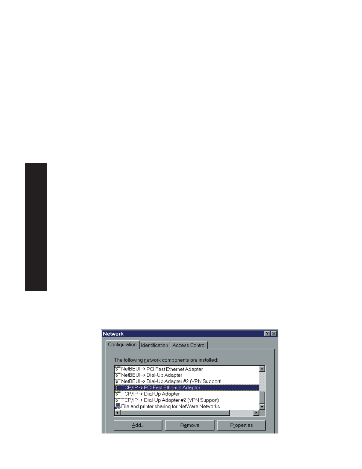
1. Select the Settings - Control Panel - Network option on the
Start Menu. You should see a screen like the one following:
English
19
Page 21

The top line in the list (NetBEUI -> PCI Fast Ethernet Adapter)
indicates that the NetBEUI protocol is installed on this PC. Your
PC will show the name of the your Network card rather than "PCI
Fast Ethernet Adapter".
The highlighted line (TCP/IP -> PCI Fast Ethernet Adapter)
indicates that TCP/IP is installed. Your PC will show the name of
your Network card rather than "PCI Fast Ethernet Adapter".
2. If neither line is present:
• Install the NetBEUI protocol by selecting Add - Protocol Microsoft - NetBEUI - OK. You may be prompted for your
Windows CD-ROM.
• If required, you can also install TCP/IP. However, depending
on your LAN environment, TCP/IP may require further
configuration.
3. If either protocol is already installed, proceed with
installation.
Windows Peer-to-peer Print Driver
With this printing method, print jobs are stored (queued) on
your PC, and then sent to the Print Server when it is available.
Setup
Before performing the following procedure, the Print Server must
be installed on your LAN, and configured as described in "Print
Server Configuration". Both the Print Server and the attached
printer should be powered ON.
1. Insert the supplied CD-ROM into your drive. If the setup
program does not start automatically, run SETUP in the root
folder.
2. Select the Installation icon, then choose the User option in
the "Setup Type" screen. This will install the Peer-to-peer
Print Driver.
English
20
Page 22
3. Follow the prompts to complete the installation. (Refer to the
Windows section of chapter "Troubleshooting" if there is a
problem with the installation.)
4. The Print Driver Setup will then run.
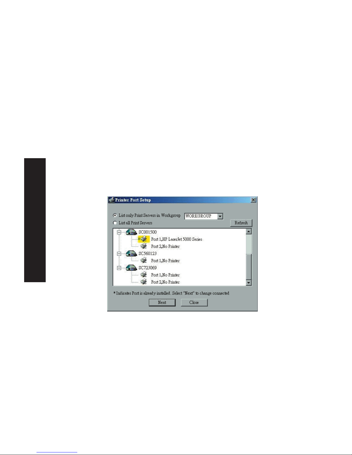
5. The LAN will be searched for Print Servers, and a screen like
the following will be displayed.
• If desired, change the Workgroup name and click Refresh.
• Select List all Print Servers to list all Print Servers, regardless
of Workgroup.
• The name of the attached printer will be displayed if possible.
If "No printer" is displayed, check that the printer is properly
connected and powered on.
If your Print Server is not listed:
• Select "List all Print Servers", and click the "Refresh" button.
• Check that both the Print Server and the printer are properly
connected, and powered on.
• Check that the Print Server has been configured, using the
Administrator installation option on the CD-ROM, and the
resulting Setup Wizard.
• If using TCP/IP, try installing the NetBEUI protocol. See the
earlier section "Checking your Network Protocols" for details.
English
21
Page 23
Then uninstall and re-install the Peer-to-peer Print Driver.
6. Select the desired printer port, and then click the "Next"
button. A pop-up message will inform you if the port has
been created successfully.
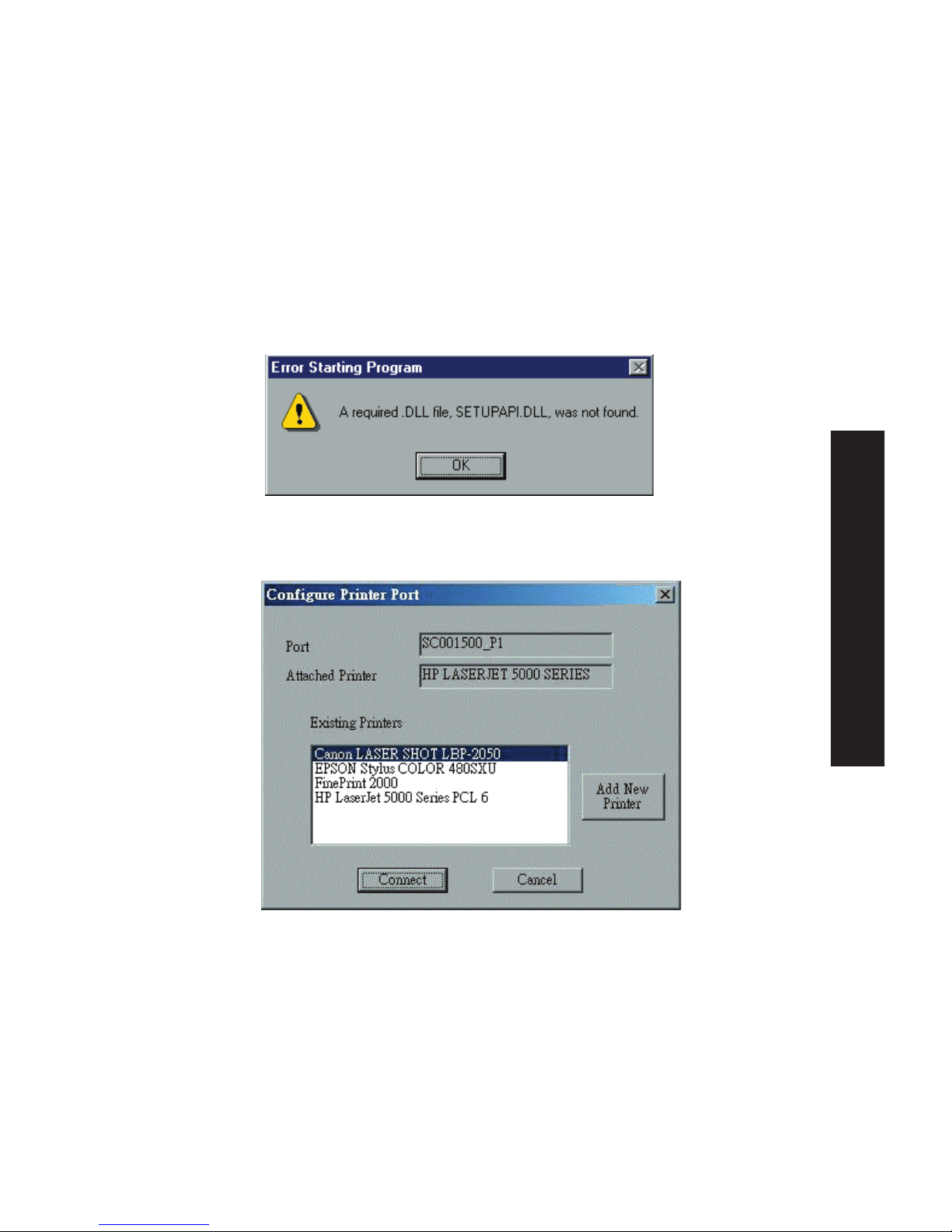
NOTE: If you see the following error message, either install
Internet Explorer 4 or later, or follow the procedure in the
"Trouble Shooting - Windows" section.
7. Then a screen like the following will be displayed:
8. Select the "Add New Printer" to run the Windows Add Printer
wizard if the desired printer is not on the Existing Printers list.
Follow the Wizard to complete the installation:
• Select the correct Printer Manufacturer and Model, or use the
"Have Disk" option if appropriate.
• We recommend changing the Printer name to indicate which
device is on. (e.g. HP2100 on SCA43600_P1)
English
22
Page 24

• If prompted about Sharing the printer, do NOT enable Sharing.
9. Click the "Connect" icon to complete the Installation. You can
now print using this printer.
• To install additional Printers, repeat steps 8 and 9.
• Use the Start menu to run this program in future. The default
installation is Start - Programs - Print Server Utility - Print
Server Setup.
Management
• Print jobs can be managed like any Windows printer. Open the
Printers folder (Start - Settings - Printers) and double-click any
printer to see the current print jobs.
• If the printer attached to the Print Server is changed, just run
this program again, and select the correct printer.
• To delete a port created by this setup program, use the Windows
Delete Port facility:
• Right-click any printer in the Printers folder, and select
Properties.
• Locate the Delete Port button. This button is on the Details or
Ports tab, depending on your version or Windows.
• If the Print Server's IP Address is changed, and you can no longer
print, delete the port (see procedure above) and re-install it.
Port Options
The options for the Peer-to-peer Print Driver are accessed via the
Port Settings button.
Use Start - Settings - Printers to open the Printers folder, then
right-click the Printer, and select Properties. The Port Settings
button is on the Details or Ports tab, depending on your version of
Windows.
English
23
Page 25
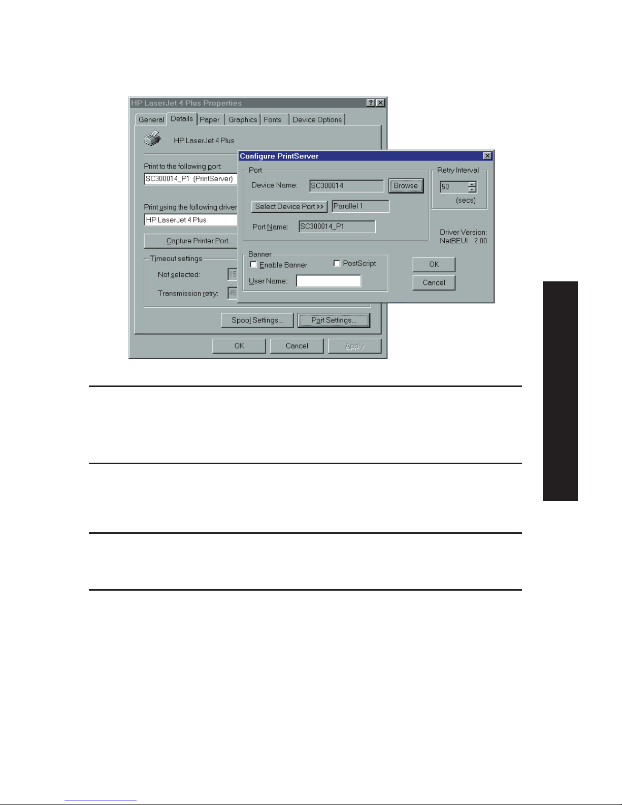
An example screen is shown below:
Port If desired, click Browse to select a different Print Server. If
the selected device has multiple ports, the Select Device Port
button can be used to select the port.
The Port Name can’t be changed after installation. This name
is shown in the Printer's Properties.
Banner Check this option to print a banner page before each
print job.
• If using a PostScript Printer, check the PostScript box.
• The User Name will be printed on the banner page.
Retry Interval Sets how often Windows will poll the Print Server to establish
a connection when the printer is busy. Increase this value if
you get too many warning messages.
Windows SMB Printing
This method requires no additional software to be installed, but
the NetBEUI or TCP/IP protocol must be installed on your PC.
Use the following procedure to install the Print Server's printer
as a Windows SMB network printer:
1. Double-click the Network Neighborhood icon on the desktop.
2. On the View menu, select Details.
English
24
Page 26

3. Locate the desired Print Server, as shown below:
• If it is the same Workgroup as your PC, it will be listed on
screen.
• If it is in a different workgroup, double-click Entire Network,
then double-click the appropriate Workgroup to open it.
4. Double-click the Print Server icon to view a Printer icon for
each printer port. The "Comment" field may indicate what
type of printer is connected to the port.
5. To install a printer, right-click the desired printer icon, and
choose "Install", as shown below. This will start the Add
Printer wizard.
6. Follow the prompts to complete the installation.
• For information about the question "Do you print from MS-DOS
programs?", see Printing from MS-DOS Programs below.
English
25
Page 27

• Select the Printer Manufacturer and Model to match the
printer connected to this port on the Print Server, and
complete the Wizard.
7. This printer will now appear in your Printers folder (Start Settings - Printers) and can be used like any other printer.
However, SMB printing is not suitable for large complex print
jobs - you should use the Peer-to-peer Print Driver instead.
Printing from MS-DOS Programs
Windows can redirect print data from a parallel port on your PC
(e.g. LPT1) to a network printer. This redirection is called "Capture
Printer Port", and is useful for MS-DOS programs. The MS-DOS
program is configured to use LPT1 (parallel port 1 on the PC), but
Windows "captures" the print data and sends it to the network
printer.
Capture settings can be set by:
• Saying "Yes" to the prompt "Do you print from MS-DOS
programs?" when installing a Network Printer.
• OR, using the Capture Printer Port menu option shown in the
figure "Install SMB Printer" above.
This will result in a dialog like the following, where you can select
the port on the PC to be captured. Normally, this will be LPT1
(parallel port 1 on the PC).
English
26
Page 28

The File menu in the Printers folder also has options for Capture
Printer Port and End Capture.
Windows with Server-based Print Queues
1. Open your Printers folder, and start the Add Printer Wizard.
2. When prompted, select Network Printer.
3. When prompted for Network Path or Queue Name, click the
Browse button, and locate the Server and Printer (or Print
Queue) that your Network Administrator advised you to use.
4. Click OK, then Next.
5. Select the correct printer Manufacturer and Model, as advised by
your Network Administrator, and click Next.
6. Follow the prompts to complete the Wizard.
The new printer will be listed with any other installed printers, any
may be selected when printing from any Windows application.
Macintosh (AppleTalk)
The Print Server supports AppleTalk (EtherTalk), PAP, ATP, NBP, ZIP
and DDP protocols, enabling Macintosh computers on the network
to view and use the Print Server as a regular AppleTalk printer.
Normally, no configuration is required.
English
27
Page 29

Software Requirements
System 7.x OS or later
AppleTalk Setup
1. Click the apple icon and choose Control Panel.
2. Click Network.
3. Ensure that EtherTalk is selected under AppleTalk Connection.
4. Click Chooser. The Chooser panel will open.
5. Click on either the LaserWriter 8 icon (recommended) or the
LaserWriter 7 icon. LaserWriter 8 makes use of the fonts
installed in the printer itself, so the printing response time is
quicker. LaserWriter 7 uses the fonts installed in the computer,
which increases network traffic and takes more printing time.
6. Select a Print Server from the printer list by clicking on the
appropriate name. The Print Server's name is recorded on a label
on the bottom of the Print Server as "Server Name". This name
consists of 8 digits and/or numbers.
7. Click on the Close box.
8. Configuration is now complete.
Printing
Printing with the Print Server installed in an AppleTalk network is
identical to normal printing. Just select File - Print and choose the
desired printer.
English
28
Page 30

Chapter 5: BiAdmin Management Utility
Requirements
This program requires:
• Windows 95, Windows 98 or ME
• Windows NT 4.0, Windows 2000 or XP
Additional Recommendations:
• Screen resolution of 800 * 600 or greater
Installation
Use the supplied CD-ROM. This CD-ROM will usually auto-run. If
auto-run is disabled on your PC, run the SETUP program in the
root folder.
• BiAdmin is always installed if the Administrator option is
chosen.
• If using the Custom option on the CD-ROM, select BiAdmin
Management Utility.
Operation
• Start the program by using the icon created by the setup
program.
• When run, the program searches the network for all active
Print Servers, and then lists them on screen, as shown by the
example screen below.
English
29
Page 31

Main Screen
Groups
On the left side of the screen is a column for Groups. Each Print
Server may be placed in a group, using the Configuration-System
Configuration-Groups menu option.
• If a group is selected, only Print Servers in that group will be
listed on the right side of the screen.
• By default, all Print Servers will appear in the [ROOT] group.
• A Print Server can only be a member of one (1) group, and
will always be a member of a group.
• Use the Configuration-System Configuration-Groups menu
option to select a group for the current Print Server.
• To create a new Group and add the current Print Server to
it, just enter a group name in the dialog. (See example
screen on the right)
English
30
Page 32

Device List
On the right side of the screen is a list of all Print Servers found
on the network. For each device, the following data is shown:
• Default Name. The Default Server Name is shown on a sticker
on the base of the device.
• Device Name. If you have not changed the name, this will be
the same as the Default Server Name.
• Printer Port. The number and type of ports is shown in the
right column.
If the desired Print Server is not listed, try the following:
• Check that the device is installed and ON, then Refresh the
list.
• Use the InitDevice - Find menu option to search for the Print
Server. You need to know the Default Name of the Print
Server. The Default Server Name is shown on a sticker on the
base of the device.
English
31
Page 33

• If the Print Server is on another LAN segment, use the
InitDevice - Attach Remote menu option to locate and display
the Print Server.
• For networks using ONLY TCP/IP, Print Servers without an IP
Address will not appear. Use the InitDevice - Set IP Address
menu option to assign an IP Address, and then Refresh the
list. You need to know the Default Name of the unlisted
device in order to assign an IP Address. The Default Server
Name is shown on a sticker on the base of the device.
Status Icons
Once a Print Server has been selected, the icons become active.
NOTE: The icons provide status information as well as access
to the selected Print Server settings. If an icon is grayed out,
that option or protocol is unavailable.
Device Information
Menu equivalent: Status - Backup/Restore
Device Information
All of the settings for the current device are displayed
in a read-only scrollable list in the left panel.
You can use the "Save to File" and "Restore to Device"
buttons on this screen to save a copy of the selected
device's CONFIG file to your PC, or restore a previously
saved file to the selected Print Server.
Printer Status
Menu equivalent: Status - Port Status
After selecting this icon, a Detail button will be
available to show more information about the printer.
English
32
Page 34

Configuration Icons
The following icons are available. Refer to the on-line help for
details of the data on each screen.
TCP/IP Configuration
Menu equivalent: Configuration - TCP/IP
Selecting this icon will allow configuration for
TCP/IP. Some models may have checkboxes for
DHCP, Bootp, and Rarp. Some models may also
display the setup data for the proprietary
"Internet Printing" feature (printing via E-Mail).
AppleTalk Configuration
Menu equivalent: Configuration - AppleTalk
Generally, no Print Server configuration is
required in order to use AppleTalk.
NetBEUI Configuration
Menu equivalent: Configuration - NetBEUI
SNMP Configuration
Menu equivalent: Configuration - SNMP
Configuration is only required if using Simple
Network Management Protocol. See Chapter 7 for
details.
Wireless Configuration
Menu equivalent: Configuration - Wireless
This Icon will be active if the selected device has
the capability to serve as a Wireless Access Point
or Wireless Stations for your LAN.
Logical Port Configuration
Menu equivalent: Configuration - Logical Port
logical port (printers) can be used in the Unix
environment.
English
33
Page 35

NetWare
Netware is not supported by SMC2622W-P and
SMC2622W-U.
Other Icons
Upgrade
Menu Equivalent: InitDevice - Upgrade
This option allows you to upgrade the firmware
for the selected Print Server. Before using this
option, you need to obtain the .BIN file for the
firmware upgrade, and copy it to the same
directory as BiAdmin.
Refresh
Menu Equivalent: None
Select this icon to update the Print Server device
listing after changing the name or IP Address.
Exit
Menu Equivalent: Help - Exit
Exit the BiAdmin program. This does not save
any changes you have made; you must Save to
Device on each screen.
English
34
Page 36

Menu Options
Status Menu
Device Info Same as Device button.
Display all the configuration and status information about the
selected Print Server. The data is presented in a scrolling,
read-only window.
Port Same as Port Status buttons.
InitDevice Menu
Attach Remote This is used to connect to a Print Server device on another
LAN segment. If your LAN does not have a Router, ignore this
option.
Connected Protocol This option allows you to designate which LAN protocol will
be used for communication between the selected device and
this application. You should select ONE protocol only.
Find Use this option to use the IPX/SPX protocol to locate a Print
Server on the LAN. Simply enter the Default Name of the Print
Server you wish to locate. The Default Server Name
is shown on a sticker on the base of the device.
Reset Device This will cause the device to reboot. This should be done
after making any configuration changes, or if the device stops
responding after some problems.
Restore Factory This will restore ALL device values to their factory
Default defaults. To restore only the current screen, use the Set to
Default button on the screen.
Set IP Address For TCP/IP networks only:
• If a Print Server does not appear on the main screen,
use this option to set a Device IP Address, Gateway IP
Address, and Network Mask to the Print Server.
• This should only be necessary if your LAN is using ONLY
the TCP/IP protocol. In other cases, BiAdmin will use
IPX/SPX to locate the Print Server even if it doesn't
have a valid IP Address.
• To locate the Print Server, enter the Default Name. The
Default Server Name is shown on a sticker on the base
of the device.
• Enter the required IP Address, Network Mask, and
Gateway IP Address.
• After saving the data to the device, refresh the listing.
The Print Server should then appear in the device list
on the main screen.
Upgrade Upgrade the firmware in a Print Server. See Upgrade Icon
for details.
English
35
Page 37

Configuration Menu
The System option allows you to:
• Change the name of the selected Print Server.
• Change the "Group" for the selected Print Server.
• Set the Network Protocols used the selected Print Server. (Any
protocols not used on your LAN may be disabled. This may
improve performance.)
The Configuration Menu also contains selections for each of the
following. These have the same effect as the corresponding Icon:
• TCP/IP
• AppleTalk
• NetBEUI
• Logical Port
• SNMP
• Wireless
Diagnostics menu
Print Test Page
Use this option to print a test sheet from the selected Print Server
port. The test print out will include status information.
Control Menu
Abort Mail Print Job
This menu option refers to print jobs, which have been received
through the proprietary "Internet Printing" feature (printing via EMail). This menu option can be used to terminate a print job,
which is not printing correctly.
NOTE: The "Abort Mail Print Job" menu option does NOT cancel IPP
print jobs.
English
36
Page 38

Chapter 6: Web Interface Setup
Overview
The Print Server models incorporate the HTTP server. This allows
you to connect to the Print Server and configure it using your
Web Browser. Most browsers should work, provided they support
tables and forms.
Preparation
Because it supports dynamic IP Address allocation using DHCP,
BOOTP, or RARP, the Print Server ships with an IP Address of
0.0.0.0. This is NOT a valid IP Address.
Therefore, you must do ONE of the following:
• Check your DHCP server (if you have one), and determine the
IP Address allocated to the Print Server.
• Use the Windows setup wizard, the supplied BiAdmin program,
or another utility to allocate a valid IP Address to the Print
Server.
• Add an entry to the arp table to associate the hardware
address of the Print Server with the desired IP address, as
follows:
arp -s IP_Address 00:c0:02:xx:xx:xx (Unix)
arp -s IP_Address 00-c0-02-xx-xx-xx
(Windows)
Where:
IP_Address is the IP Address you wish to assign to the Print
Server.
00:c0:02:xx:xx:xx is the hardware address of the Print Server.
Example (Unix):
arp -s 192.168.0.21 00:c0:02:12:34:56
37
English
Page 39

Example (Windows):
arp -s 192.168.0.21 00-c0-02-12-34-56
NOTE: The hardware address of the Print Server is shown on a
sticker on the base of the device. The diagnostic printout can
also be used to find the Print Server's IP address and hardware
address. (Press and hold the diagnostic button for 2 seconds.)
Connecting to the Print Server
1. Start your Web Browser.
2. In the Address box, enter HTTP:// followed by the IP Address
of the Print Server (e.g. http://192.168.0.21).
3. You will then be prompted for the password. If no password
has been set, just press ENTER.
4. Use the menu bar on the top of the screen to move about.
Remember to save each screen before changing to a different
screen.
38
English
Page 40

Configuration Screens
AppleTalk
AppleTalk zone This determines which Apple systems can gain
access to this printer.
Printer Object Type These are text fields, used to describe the printer
driver used for each port. The Print Server is
designed to work with LaserWriter (or 100%
compatible) printers.
Communication Protocol Sets whether the port uses ASCII or Binary
Communication Protocol. The default is binary.
English
39
Page 41

NetBEUI
Domain Name Enter the designated work group to be serviced by
the Print Server. This field is not case sensitive, so
names with different case will be considered to be
the same name.
Response Time Set how fast jobs are sent to the printer. The
default value of zero (0) delay should be increased
only if your printer cannot cope with any delays.
Abort Print Job if Error YES terminates a print job if a printing error
occurs. NO (default) will try to continue but may
cause print errors. If print errors occur, try setting
this value to YES.
English
40
Page 42

SNMP (Simple Network Management Protocol)
SysContact Text Field - Name of the contact person.
SysLocation Text Field - Location of the contact person.
Management Stations
Station No. Select the Management station (1..4), and click the Get Data
button to update the display for the selected item.
IP Address Enter the IP Address of the management station, which has
the SNMP program installed.
Community This is a text field. Enter the name of the community.
Access Select the desired level of access.
Trap Receivers
Receiver No. Select the Trap Receiver number (1..4), and click the Get
Data button to update the display for the selected item.
IP Address Enter the IP Address of the Trap Receiver, which will be sent
the Trap message.
Community This is a text field. Enter the name of the community.
Enable Check to enable; select the severity level.
Note: Currently, all traps are level 1.
English
41
Page 43

TCP/IP
IP Address IP Address assigned to this device. If using dynamic IP
Addresses (DHCP, BOOTP, rarp), this should be left at
0.0.0.0.
Subnet Mask If the Router (Gateway) Address is 0.0.0.0, the Subnet Mask
(Network Mask) should also be left at 0.0.0.0. If you have a router, enter
the Subnet mask for the segment to which the Print
Server is attached.
Gateway Address If your network segment has a router or gateways, enter its
IP Address here. Otherwise, leave the address as 0.0.0.0.
Connection
Delay before Sets how long the Print Server should wait before retrying a
reconnection TCP/IP connection, which is lost. Allowable values are from
attempts 0 to 255 seconds, with 2 as the default.
Number of Set how many attempts at reconnection will be made. After
reconnection attempts that, the TCP/IP session will be terminated.
Allowable values are from 0 to 255, with 254 as the default.
English
42
Page 44

Configure Server
Print Server Name Change the default name if you wish. The new name must
not contain any spaces or blanks.
Password Enter the device password, and again in the Verify field.
Once a password is entered, it is required in order to gain
access and change the configuration.
Enable Protocols Non-TCP/IP protocols may be disabled if they are not
required on your LAN.
English
43
Page 45

Wireless Configuration - SMC2622W-P & SMC2622W-U
On the SMC2622W-P and SMC2622W-U, this Wireless screen will
be available.
The settings on this screen must match the other Wireless stations
in order for communication to occur.
Configuration
Regulatory It is illegal to use this device in any location outside of the
Domain regulatory domain.
Station name This is the same as the Device (Host) Name on the WAN
screen. On your PC, some Wireless status screens may
display this name as the Access Point in use.
SSID(ESSID) To communicate, all Wireless stations MUST use the same
SSID/ESSID.
The default value is null.
Note! The SSID is case sensitive.
Channel No. The default Channel for the USA and Canada is 3.
Select the value you wish to use on your Wireless LAN. If
you experience lost connections and/or slow data transfers
you may need to experiment with different channels to see
which is the best.
English
44
Page 46

Network Type Select the correct value for your Wireless LAN.
• 802.11 Ad-hoc mode is used when there is no Wireless
Access Point, and each Wireless station communicates
directly with other Wireless stations. This is the current
standard.
• Ad-hoc mode is used when there is no Wireless Access
Point, and each Wireless station communicates directly
with other Wireless stations. This is the older standard.
• Infrastructure mode is used when each Wireless station
connects to the Wireless Access point. This also provides
access to the wired LAN.
Link Info Button Click this button will open the sub screen.
WEP Data Privacy
Off If OFF (default), data is NOT encrypted before being
transmitted.
64 Bit Encryption If selected, data is encrypted, using the default key, before
being transmitted.
The receiving station must be set to 64 Bit Encryption, and
have the same Key value in the same position in its key table.
Otherwise, it will not be able to decrypt the data.
Default Key
Select the key you wish to be the default. Transmitted data is
ALWAYS encrypted using the Default Key; the other Keys are
for decryption only.
Key Table:
This table is used when Encrypting and Decrypting data. All
stations, including this Access Point, always transmit data
encrypted using their default key. The key number (1, 2, 3, 4)
is also transmitted. The receiving station will use the key
number (1, 2, 3, 4) to determine which key value to use for
decryption. If the key value does not match the transmitting
station, decryption will fail.
The easiest way to ensure there are no problems is to have
every Station, including the Access Point, use the same key
table (all entries identical). Then, it does not matter which key
is used as the default key.
128 Bit Encryption If selected, data is encrypted using the key before being
transmitted. The receiving station must be set to use 128 Bit
Encryption, and have the same Key value. Otherwise, it will
not be able to decrypt the data.
Key
Enter the key value you wish to use. Other stations must have
the same key
WEP Authentication Options are "Open System" or "Shared Key".
Some Wireless cards do not support both methods. Check your
Wireless card's documentation to determine the correct value.
Ensure that all Wireless stations use the same setting as the
Access Point.
English
45
Page 47

Other Screens
Server Status
This screen shows server system data and the current settings for all
of the other screens. It is read-only; no data can be input on this
screen.
Printer Status
This screen displays the current status of each port. For each port,
the following data is listed:
• Connected Printer - the model name of the printer connected to
the port, if the printer name is known. (If the printer is not bidirectional, this information is unavailable.)
• Status - the current status of the printer (On-line, Off-line, Out of
paper)
• Printing Information - this will show either Idle or Printing.
Logical Printers
Logical Printers (ports) can be used under Unix. For each Logical
Printer, the following fields are available:
Logical Printer Select the Logical Printer Port you wish to configure. (L1 to
(Port) L3 or L1 to L8, depending on your model)
Click the Get Data button to update the display with the
current data for the selected logical printer.
Pre-string The printer control string (in hex) to be sent to the printer
before each print job. This string cannot exceed 15
characters.
Post String The printer control string (in hex) to be sent to the printer
after each print job. This string cannot exceed 15
characters.
Convert LF to CR+LF If checked, LF (line feed) characters are changed to CR+LF
(carriage return + line feed).
English
46
Page 48

Chapter 7: Special Features
Overview
The Print Server has three (3) special features:
• IPP (Internet Printing Protocol) support
• Proprietary Internet Mail Printing system.
• SNMP (Simple Network Management Protocol) is fully
supported by all models.
Internet Printing Protocol (IPP)
IPP (Internet Printing Protocol) is a new standards-based system
to allow remote printing from a PC to any accessible printer.
Normally, the printer will be attached to a computer or other
device, which functions as an IPP Server.
For client PCs, it is necessary to install a compatible IPP Client
program. The Client must also know the IP Address or URL or the
IPP Server.
IPP Server Configuration
The Print Server contains the necessary firmware to act as an
IPP Server. No additional configuration is necessary. However,
the following requirements must be met.
• The Print Server must have a valid IP Address. For printing via
the Internet, the Print Server's IP Address must be external
(allocated by your ISP), rather than an IP Address on your
local LAN.
• Any Router, Gateway or Firewall linking your LAN to the
Internet must NOT block the IPP protocol.
• You must advise clients of the correct URL or IP Address of
the IPP Server. To use a URL rather than an IP Address, you
need to register the domain name for the URL.
English
47
Page 49

• Unless clients are using Windows 2000, you must provide your
clients with the supplied IPP Client software. If it is not
convenient to provide the CD-ROM, supply the IPP_CLIENT.EXE
file, located in the IPP folder.Connected Printer - the model
name of the printer connected to the port, if the printer name is
known. (If the printer is not bi-directional, this information is
unavailable.)
IPP Client Setup - Windows 95/98/ME/NT 4.0
The IPP Client Software can be installed on any of the following
systems:
• Window 95/98/ME
• Windows NT 4.0
Installing from the CD-ROM
1. Insert the CD-ROM in your drive. If the program does not start
automatically, run the SETUP program in the top-level folder.
2. Follow the prompts until you reach the Select Installation
screen, and select IPP Client.
3. At the next screen, select the Install IPP Client option.
4. Click Next, and step though the remaining screens to
complete the installation.
Installing using IPP_CLIENT.EXE
1. Run this program to unzip the included files.
2. The IPP Setup program will then run.
3. Follow the prompts to complete the installation.
English
48
Page 50

IPP Client Configuration (Windows 95/98/ME/NT 4.0)
1. Run the "Add IPP Port" program entry created by the
installation. A screen like the following will be displayed.
2. If Internet access from your location is via a Proxy Server,
check Access IPP Server via Proxy Server, and enter details of
your Proxy Server. (This will be the same as your Browser
configuration.)
3. Enter the IP Address or URL of the IPP Server.
4. Click Select Device Port to view the available ports on the IPP
Server, and select the appropriate port. A connection to the
IPP Server will be established at this time.
English
49
Page 51

5. Click Save to create the IPP port on your system. You will see
a message confirming that the port has been created, then
the following dialog:
6. Either
a) select an existing printer to use the new port, and click OK.
Or:
b) click the Add New Printer button to create a new printer to
use the IPP port. This will start the Add Printer wizard. Follow
the prompts to complete the process. Ensure that the new
printer uses the IPP port.
7. Installation is now complete.
• To create additional IPP Ports, repeat the entire procedure.
• The Proxy Server and other options are set individually for
each IPP Port.
English
50
Page 52

Changing the IPP Port Settings
After the IPP port is created, you can reach the screen shown in
figure "IPP Port" using the Windows Port Settings button:
1. Open the Printers folder (Start - Settings - Printers)
2. Right-click the IPP Printer, and select Properties.
3. Locate and click the Port Settings button (Details or Port tab,
depending on your version of Windows).
There are 2 settings - Retry Interval and Retry Count - which can
be adjusted if you have problems connecting to the IPP Server.
• Retry Interval sets the time interval (in seconds) between
connection attempts. Increase this number if you have a poor
connection, or the remote server is very busy.
• Retry Count sets how many connection attempts will be made.
Increase this number if you have a poor connection, or the
remote server is very busy.
English
51
Page 53

IPP Client Setup - Windows 2000
Windows 2000 has its own IPP Client, and there is no need to
install the supplied IPP Client Software. To use Windows 2000's
IPP Client with the Print Server, follow this procedure:
1. Start the Add Printer wizard.
2. Select Network Printer, and click "Next" to see the Locate
your Printer screen, as shown below.
3. Select Connect to a printer on the Internet or on your
Intranet, and enter the URL of the IPP Server as follows,
where ip_address represents the IP Address of the IPP Server,
and 631 is the port number.
Parallel Port 1 ip_address:631/ipp/P1
NOTE: This entry is case sensitive. It must be entered as
shown, with "ipp" in lower case, and P1 in UPPER case.
English
52
Page 54

4. If the connection can be established, and the printer on that
port is on-line, the following dialog will be displayed.
5. Click "OK", and then select the printer manufacturer and
model to match the printer connected to the port on the IPP
Server.
6. Click "Next", and complete the Wizard.
The IPP printer is now ready for use.
Using IPP Printers
The IPP Printer can be selected and used like any other Windows
printer. If the IPP Server is not on your network, your Internet
connection needs to be active.
If you wish to check the availability of the remote IPP Server,
you can use the Query IPP Printer program installed with Add
IPP Port.
An IPP Server may be unavailable for any of the following
reasons:
• It is powered off.
• A printer problem has caused the IPP Server to cease
responding, and a restart (reboot) is required.
• The Server's IP Address has changed.
• The Internet connection for the IPP Server is down.
• Network congestion causes the connection attempt to time
out.
English
53
Page 55

If using the supplied IPP Client software, there are 2 settings Retry Interval and Retry Count - which can be adjusted if you
have problems connecting to the IPP Server.
See the previous section "Changing the IPP Port Settings" for
details.
Internet Mail Printing
The Internet Mail Printing System allows users to print data to
your printer across the Internet. Users send the Internet Print
Server an E-Mail, with the print job normally sent as an
attachment to the E-Mail. The Print Server will retrieve the EMail and print it.
System Requirements
Mail Server
• Accessibility. The Mail Server must be accessible by the
intended clients or users. Normally, this means a permanent
connection to the Internet.
• Protocols. The Mail Server must support the POP3 and SMTP
protocols. The Internet Printing System uses these protocols
and the most common E-Mail formatting standards:
• MIME (Multipurpose Internet Mail Extensions)
• Base64 Encoding (for mail attachments)
Internet Print Server
• TCIP/IP Protocol. The LAN must use the TCP/IP protocol.
• Mail Server Access. The Print Server must be able to access
the Mail Server using a single IP address.
• Mail Account. The Print Server must have a Mail Account.
Users print by sending an E-Mail to this mail account.
English
54
Page 56

User (Client) Requirements
• Internet Connection. Either through a LAN, or dial-up.
• E-Mail address. This is used to notify the user that their print
job has been done, or if there any problems.
• Printer Driver. Users must have a printer driver which matches
the printer connected to the remote Internet Print Server.
• Print Capture Software. To print more than plain text, users
require InterNet Printing Port software to capture the print
job and convert it into an E-Mail attachment.
The Internet Printing Port software is available for the following
operating systems:
• Microsoft Windows 95
• Microsoft Windows NT 4.0 or later
Internet Mail Printing Configuration
The Print Server must be configured with the data in the
following table.
The supplied BiAdmin utility program, or the Web interface can
be used to set the following entries on the TCP/IP screen.
Mail Server IP Address The IP Address of the E-Mail Server used by the Print
Server.
Mail Account The name of the E-Mail Account used by the Print
Server.
Mail Account Password Enter the password for the above Mail Account here.
Check Mail Interval Sets how often to check for mail. Values range from 0 to
65.535 minutes, with 0 meaning a continuous
connection and 1 as the default.
Print Banner If YES (default), a banner page is printed to identify the
owner of the print job.
Redirect Mail Account Jobs, which cannot be printed, will be sent to this
account. If blank, unprintable jobs will be discarded.
Default Printer Number Printer number for all Internet print jobs. Only one port
can be selected. Users on the LAN can also use this
port.
Print every E-Mail If ON, then all E-Mail received is printed. Otherwise, only
E-Mail from the InterNet Printing Port will be printed.
English
55
Page 57

Activate Response Mail If YES, all print jobs receive an E-Mail response. If NO,
only users who set this option in their InterNet Printing
Port software receive an E-Mail.
Printer Model ID String This text field identifies the printer used for Internet
printing. This value is sent to remote users upon request.
User Software
The software provided for remote users (InterNet Printing Port)
should be installed by everyone intending to use Internet
printing. Otherwise, remote users can print correctly only if:
• They send an E-Mail directly to the Print Server Mail Account,
using their normal E-Mail application.
• The E-Mail contains plain text only.
• The Internet Print Server is configured with Print every
E-Mail ON.
Installation of the InterNet Printing Port software will create a
new printer port. After attaching the correct printer to this port,
users can print to the Internet Printer using any Windows
application.
English
56
Page 58

Installation - User Software
1. Run the InterNet Printing Port installation program SETUP.EXE
2. Default values for the installation are:
• Directory - C:\Program Files\Internet_Printer
• Start Menu folder - InterNet Printing Port Driver
3. You will then see the Configure Port screen, as shown in the
following screenshot.
4. The following data must be provided.
Port Name Enter a descriptive name (e.g. "WAN") for the new
printer port.
Remote Printer The E-Mail address for the Internet printer. Your print
E-mail Address jobs will be sent to this E-Mail address.
Mail Server Name This is the name or IP Address of your Mail Server. If you
or IP Address are on a LAN, ask the LAN Administrator. If using a dial-
up connection, use the data provided by your ISP.
Your Internet The normal address that people use to send you E-mail.
E-mail Address
Retry Interval (Seconds) If unable to connect to the E-Mail server, retry after this
time period (1 to 255 seconds, 30 is usually OK).
Reply Notification Mail Check to receive an E-Mail when your print job has been
processed.
English
57
Page 59

5. On completion, a new printer port will have been created.
Using the new Port
The Windows Control Panel is used to connect the correct printer
to the InterNet Printing Port. In Windows 95/NT, the procedure is:
1. Select the Printer, which matches the remote printer, and then
choose Properties, as shown in the example below.
2. Select the new port - WAN (InterNet Printer) in the example - as
the port for this printer.
• If you do not have the correct printer driver, or you wish to
create another printer using an existing driver, use the Windows
Add Printer facility.
• Using the Windows Port Settings or Configure Port facility will
reveal the same Configure Port screen shown in figure "InterNet
Printer Port".
• If you wish to print to multiple Internet Printers, use the
Windows Add Port facility to add a new InterNet Printer port.
Ensure that the correct data is entered in each port, and that
each port has a unique name.
English
58
Page 60

Checking the Printer Driver
To make sure that the correct printer driver for the remote printer
is installed on your system, you can use the InterNet Printing Port
to send an E-Mail to the Internet Printer. The procedure is as
follows:
1. Connect your default printer to the InterNet Printing Port.
2. Check that "Reply Notification Mail" in the InterNet Printing
Port is ON.
3. From Notepad or another text editor, print a short message (e.g.
"This is a test print") to the Internet Printer.
You will receive a reply E-Mail containing the "Printer ID" which
will identify the printer attached to the Print Server. If this does
not match the printer driver you are using, install the correct
printer driver.
Printing through the Internet
1. Create or open the document you wish to print.
2. Select the Printer connected to the InterNet Printing Port.
3. If you do not have a permanent Internet connection, establish a
connection now. (Note: The InterNet Printing Port will NOT
establish a dial-up connection, but it will send the E-Mail the
next time you are connected.)
4. Print the document.
English
59
Page 61

5. The InterNet Printing Port will generate an E-Mail and send it to
the remote printer. The document will be encoded and sent as
an attachment to the E-Mail. You will see a progress screen
similar to the example below:
6. Close the Internet connection if you opened it in Step 3.
7. If the "Notify after print job" option is set, you will receive an
E-Mail when your job is printed.
Canceling a Print Job
Users cannot cancel a Print Job once it has been sent, but Print
Jobs can be cancelled at the Print Server. In BiAdmin, the Control
- Abort Mail Print Job menu option can be used to cancel a print
job, which has already started printing.
SNMP
The Print Server supports SNMP (Simple Network Management
Protocol). This allows network supervisors to monitor and control
the Print Server using network management platforms such as HP
OpenView, IBM SystemView, etc.
The appropriate MIB file must be imported into your SNMP
management program using the Import-Compile command. Check
your management program for details on this procedure. The MIB
files are provided in the Mib folder on the CD-ROM, as follows:
Mib1p.mib PS 7100, SMC2622W-U
English
60
Page 62

Configuring the Print Server for SNMP
Before using a SNMP Management station to manage the Print
Server, the following settings should be assigned to it, in addition
to the IP Address, Gateway Address, and Subnet Mask.
SysContact Text Field - Name of the contact person.
SysLocation Text Field - Location of the contact person.
Management Station Up to 4 Management Stations can be entered.
IP Address(s)
Trap Receiving Up to 4 Trap Receiving Stations can be entered.
IP Address(s)
Management Station Settings
For each Management Station, the following fields are available:
Access Permission Options are:
Read Only
Read/Write
Not Accessible
Community String Leaving this blank will disable management by this
station.
Trap Receiving Station Settings
For each Trap Receiving Station, the following fields are available:
Community String Leaving this blank will disable management by this
station.
Trap Enable Use this option to Enable/Disable Trap Receiving by this
station.
Trap Severity In this version, all traps are level 1.
English
61
Page 63

Chapter 8: Troubleshooting
Overview
If you encounter printing difficulties, please refer to the
appropriate section.
If, after following the advice in these documents, the Print
Server still does not function properly, please contact your
dealer for further advice.
Hardware & LAN Problems
Problem No. 1 All the Print Server's LEDs are off.
Solution No. 1 Check the power supply or power connection.
Problem No. 2 Print Server's status light continuously stays
lit.
Solution No. 2 Reset Print Server by unplugging the power
supply and plugging it back in.
Problem No. 3 Print Server's status light and power light stay
on continuously and do not turn off.
Solution No. 3 Reset the Print Server by unplugging the
power supply or by pushing the reset push
button, if fitted.
Problem No. 4 The Print Server unit cannot be found on the
LAN, so configuration is not possible.
Solution No. 4 If using 10/100BASE-T:
• Check the Hub. The link LED for the port to which the Print
Server is connected should be ON. If it is Off, there is a
problem in the network cable.
• On the Print Server, check the LED(s) next to the connector. If
the LED is not ON (or neither LED is On, if there are 2), the
network connection is not working.
English
62
Page 64

Check the Ethernet cable and connectors.
If using TCP/IP:
• Ensure that there are no routers between the Print Server and
the PC used for configuration.
• Ensure that the PC used for configuration has the TCP/IP
network protocol installed. Test its network connection by
seeing if you can locate other LAN devices from the PC. (e.g.
Use Network Neighborhood and try to browser the network.)
Problem No. 5 I am using DHCP, and getting an IP Address
conflict involving the Print Server.
Solution No. 5 If the Print Server is left on, but the DHCP
server is turned off, then the Print Server will
retain its IP Address without the DHCP Server
being aware of it. Simply reset the Print Server
so it will obtain a new IP Address.
This problem would also arise if you assigned static IP Address,
which is within the range used by the DHCP server. If so, use
another address, which is NOT within the range used by the
DHCP server.
Problem No. 6 The Wireless is not working (for SMC2622W-P
and SMC2622W-U)
Solution No. 6
• Make sure the PCMCIA card is inserted (check the WLAN LED).
• If the Print Server is in "Infrastructure" mode, make sure the
LAN port is not connected.
Note! SMC2622W-P and SMC2622W-U will disable the wireless if
LAN connection is detected.
English
63
Page 65

AppleTalk (Macintosh)
Problem No. 1 Why do I get an incorrect printout?
Solution No. 1 Some possible reasons are:
• You may have chosen Binary encoding to print the file. Try to
use ASCII encoding.
• Some of the fonts, which are in your print file may not be
supported by the printer. Try selecting LaserWriter 7 instead
of LaserWriter 8.
Problem No. 2 Can't find the Print Server's name in the Chooser.
Solution No. 2 Try the following:
A.Make sure that AppleTalk is on (the button next to Active is
highlighted in the Chooser).
1. Make sure the printer has been on and in the READY state for
a few minutes.
2. Make sure the printer has not been renamed since its last
appearance in the Chooser.
3. If the printer resides on a network with multiple zones, make
sure the correct zone is selected from the AppleTalk Zones
box in the Chooser.
Problem No. 3 My document didn't print to the right printer.
Solution No. 3 Check the following:
• Another Print Server with the same name may have received
your print job. Ensure all Print Servers have unique names.
• Make sure your application output encode is set to ASCII. If
not, change it to ASCII.
Problem No. 4 My file doesn't print with the correct fonts.
Solution No. 4 Try changing your printer driver to LaserWriter 7.
Problem No. 5 My EPS file doesn't print with the correct fonts.
Solution No. 5 This is a problem that occurs in some
English
64
Page 66

application programs. Try downloading the
fonts contained in the EPS file before printing
the saved EPS file.
Problem No. 6 I can't select the "Remaining from:" item in the
print dialog box.
Solution No. 6 If you have selected the Layout value, "2 Up",
or "4 Up", you cannot access the Remaining
from item. Choose other selections.
Problem No. 7 A cover page prints either on the first or the
last page of the document.
Solution No. 7 Select one of these solutions:
• Turn the cover page feature off.
• Insert extra page breaks in your document to avoid the cover
page printing on the first or last page of your document.
• Install the Apple LaserWriter 7 driver. You are having trouble
printing with the Apple LaserWriter 8 driver.
Problem No. 8 Why do I have trouble printing with the
LaserWriter 8?
Solution No. 8 Your application software may not be
compatible with the LaserWriter 8 driver or
your system may not meet the requirements of
the LaserWriter 8 driver. Use the Apple
LaserWriter 7 driver instead.
Problem No. 9 The colors on my printed output do not match
the colors on my computer screen.
Solution No. 9 When the printer receives a color file, it tries
to match the printed output color to the screen
color. Sometimes the printer cannot match up
the colors as closely as wanted. To alleviate
this problem, perform the following steps:
English
65
Page 67

• Choose "Calibrated Color/Grayscale" in the Print pop-up menu
in the Print Options dialog box. The printer will make
adjustments to match the colors.
• Check your monitor to make sure all settings (for example,
brightness) are adjusted correctly.
Problem No. 10 When I send a print job, I get a PostScript
Command error or no print out.
Solution No. 10 Check the communication protocols. The
computer, Print Server and printer must all be
configured to the same communication
protocol.(either Binary or ASCII).
To configure your system:
1. Choose which protocol you are going to use. You should check
your printer; it may not give you a choice.
2. Set your printer to the correct protocol.
3. Use the computer's Print submenu to configure your computer
to use the protocol you have chosen.
4. Configure the Print Server to use the same protocol as the
printer and computer.
Windows Printing Problems
Problem No. 1 When I tried to install the Printing software for
Peer-to-Peer printing, I received an error
message and the installation was aborted.
Solution No. 1 This may be caused by an existing installation
of the printer port software. Before attempting
another installation:
• Remove the existing installation
• Restart your PC
To remove an existing printer port installation:
1. Open Start - Settings - Control Panel - Add/Remove Programs
English
66
Page 68

2. Look for an entry with a name like "Shared Port", "Shared
Printer Port", "Print Server Driver" or "Print Server Port".
3. Select this item, click "Add/Remove", and confirm the deletion.
Problem No. 2 On Windows 95, I installed the Print Port Driver
for Peer-to-Peer Printing, but when I selected a
port on a Print Server and clicked "Add", the
printer was not installed.
Solution No. 2 Try installing the Printer using the standard
Windows tools, as follows:
1. Start the Add Printer Wizard.
2. Select Network Printer when prompted "How is the printer
attached to your Computer?" and click Next.
3. When prompted for the Network Path or Queue, enter a dummy
value such as \\123, as shown below. (Do NOT select Yes for
"Do you print for MS-DOS programs?")
4. The printer wizard will display a message stating that "The
Network Printer is off-line". This is OK. Continue the Add
Printer Wizard until finished.
5. Go to the Printers folder (Control Panel-Printers). The printer
icon will be grayed out indicating the printer is not ready.
English
67
Page 69

6. Right-click the Printer, and select Properties. Then select the
Details tab, as shown below.
7. Click the Add Port button. On the resulting screen, select
Other, then Printer Server, as the port to add, as shown below.
English
68
Page 70

8. Click OK to see the Print Port Configuration screen, as shown
below.
9. Click the Browse Device button, select the desired Print
Server, and click OK.
10.Click OK to return to the Printers folders, and right-click on the
Printer. Ensure that the Work off-line option is NOT checked.
The Printer should no longer be grayed out, and is ready for use.
Problem No. 3 I connected and configured a WPS (Windows
Printing System) printer as described, but I
can't get the print job to print.
Solution No. 3 Printer drivers for WPS printers poll the printer
before sending print data. Since the printer is
networked, the printer is not found and no data
is sent. The solution is to add your printer as a
network printer as described in Solution 1 above.
English
69
Page 71

Note: The screens shown in Solution 1 are from Windows 95.
Other versions of Windows may look slightly different, but the
process is identical. If available, Sharing for the printer should
NOT be enabled.
Problem No. 4 When printing from some software applications
such as Power Point, it takes a long time and
the print out is incorrect.
Solution No. 4 The problem is due to the printer, which is
being configured to Start printing after the
first page is spooled. To change this setting:
• Go to Control Panel - Printers and click on your printer.
• Then select File - Properties - Details.
• When the Details screen appears, click the Spool Settings
button.
• When the Spool Settings dialogue box appears, choose Start
printing after last page is spooled and click OK.
Problem No. 5 A printing device connected to the Print Server
port cannot print or prints garbage.
Solution No. 5 Check the following:
• Cable connection between Print Server and printer.
• Serial port configuration, if a serial device.
• Printer driver in the application program or Windows matches
the printer.
Problem No. 6 The Configuration button on the Printer Status
screen in BiAdmin is grayed out, even though
my printer is bi-directional.
Solution No. 6 The button is unavailable if the printer is busy.
You must wait until the printer is idle.
English
70
Page 72

SMC2622W-P Print Server
General Specifications
Power Consumption
3w max.
External Power Adapter
12V DC
LEDs
4
Parallel Port
1 Centronic female DB-25
connector
Ethernet Connector
10/100BASE-T
IEEE 802.11b
Wireless PC Card Slot
FCC / CE
Class B
SMC2622W-U Print Server
Power Consumption
3watts max.
External Power Adapter
12V DC
LEDs
4
USB Port (1.1)
1
Ethernet Connector
10/100BASE-T
IEEE 802.11b
Wireless PC Card Slot
FCC / CE
Class B
Environmental Specifications
Operating Temperature
0 ~ 40°C
Storage Temperature
-10 ~ 70°C
Shipping Temperature
-40 ~ 70°C
Operating Humidity
10 ~ 80%
Storage Humidity
5 ~ 90%
Shipping Humidity
5 ~ 100%
English
71
Appendix A
Specifications
Page 73

Parallel Port Pin Assignments
* Data signals will be driven by some but not all peripheral devices.
Pin Signal Name Direction
1 - Strobe To printer
2 +Data 0 To printer
3 +Data 1 To printer
4 +Data 2 To printer
5 +Data 3 To printer
6 +Data 4 To printer
7 +Data 5 To printer
8 +Data 6 To printer
9 +Data 7 To printer
10 - ACK To Server
11 + Busy To Server
12 + Paper End To Server
13 + Select To Server
14 - Auto Feed To printer
15 - Error To Server
16 - Init To printer
17 - Select In To printer
18-25 GND Ground
Regulatory Approvals
SMC2622W-P, SMC2622W-U
FCC Statement
This equipment generates, uses, and can radiate radio frequency
energy. It has been tested and found to comply with the limits
for a Class B digital device, pursuant to Part 15 of the FCC rules.
These limits are designed to provide reasonable protection
against harmful interference in a domestic environment.
Operation is subject to the following two conditions:
• This device may not cause harmful interference.
• This device must accept any interference received, including
interference that may cause undesired operation.
English
72
Page 74

CE Marking Warning
This is a Class B product. In a domestic environment this
product may cause radio interference in which case the user may
be required to take adequate measures.
Safety Instructions
For your own safety, and to protect your Print Server, please
observe the following safety advice.
1. Unplug this device from its power source before cleaning. Use
only a slightly dampened cloth for cleaning. Do not use liquid
or aerosol cleaners.
2. Avoid using this product near water. Exposure to water poses
an electric-shock hazard.
3. Do not place the Print Server on an unstable surface. The
device may fall causing serious damage to the device.
4. This device should only be used with the power supply type
specified on the marking label. If you are not sure of type of
your local power supply, consult your dealer or the local
power company.
5. Do not pinch, crimp or otherwise damage the power cord. If
exposed to foot traffic, ensures that the cable is properly
shielded and does not pose a tripping hazard.
6. If using an extension cord, makes sure the total ampere rating
of the products using the cord does not exceed the extension
cord's ampere rating.
7. Do not attempt to service this device, as opening or removing
casing may expose you to dangerous voltage points or other
risks. Refer all servicing to qualified service personnel.
8. The Print Server should be serviced by qualified service
personnel under the following conditions:
• The power cord is damaged or frayed.
• Liquid has been spilled onto the product.
English
73
Page 75

• The product has been exposed to rain or water.
• The product does not operate normally in accordance with the
operating instructions.
• The device has been dropped or the casing has been damaged.
Appendix B
Wireless PCMCIA Adapter Installation
Both Print Servers SMC2622W-U and SMC2622W-P are preconfigured for the Wireless adapter SMC2632W V.2.
In case you use one of the following wireless adapter cards
• SMC2632W (previous model sold by SMC)
• adapter cards based on Intersil PRISM 2.x and 3.0
you need to proceed with the installation as described below.
On the included CD-ROM SMC provides in sub-directory
"\Tools\Wireless" the "Wireless Diagnostic program" and
firmware (FW) for Intersil and A+R adapter cards.
Installation Procedure
1. Make sure that the physical installation is ready:
• Wireless LAN is inserted
• LAN cable inserted
• Printer is connected
• Power ON device
2. Start the installation program that is available on CD-ROM
(folder: tools\wireless\wl_diag.exe). The screen below will be
displayed.
Please choose the LAN card, that is connected to your wired
network and click OK.
English
74
Page 76

3. Browse devices and select device.
4. Run "Wireless Diagnostic Program" to find out which Wireless
adapter card (Intersil or A+R) is inserted. You will receive one
of the following messages:
a) Current firmware version does not support your wireless LAN.
This means you need to upgrade your current driver. Download
the required wireless driver to device and click "Next". This will
open the "Wizard".
English
75
Page 77

b) Current FW version supports the wireless LAN inserted.
As the current firmware is supported, continue with the device
configuration and click "Next". This opens "Wizard" for setup.
c) No wireless LAN card detected or this device does not support
the wireless LAN card.
This message will be displayed in conjunction with Intersil or
A+R adapter cards. In order to get further information how to
proceed, please contact your vendor to receive further
information. On the CD-ROM firmware for Intersil or A+R adapter
cards is included.
5. Continue with the configuration by clicking "Next". Follow the
instructions displayed on the screens in order to complete the
installation.
English
76
Page 78

Appendix C
Network Server Configuration
Windows NT Server
Preparing for TCP/IP Printing
If using Windows NT 4.0, Microsoft TCP/IP Printing Support must
be installed.
• If it is already installed, proceed to Adding a TCP/IP Remote
Printer.
• Otherwise, the procedure to install TCP/IP printing support is
as follows.
Windows NT 4.0
• Go to Start-Settings-Control Panel-Network.
• Click the Service option and ensure that Microsoft TCP/IP
Printing is enabled. If it is not enabled, select the Add option
and enable it as usual.
• If you added services in step 2, reboot the computer for the
changes to take affect.
Adding a TCP/IP Remote Printer
Windows NT 4.0
1. Go to Start-Settings-Printer and invoke the Add Printer wizard.
2. When prompted with This printer will be managed by, select
My Computer and click Next.
3. Select Add Port…, then select LPR Port and click New Port.
4. In the Name of Address of server providing lpd: Dialog box,
enter the Print Server's IP address.
English
77
Page 79

5. In the Name of printer or print queue on that server dialog
box, enter the appropriate logical printer number (L1..L3, or
L1..L8, depending on the model) as previously configured on
the Print Server.
6. Click OK. When returned to the Printer Ports window, simply
select Close and then install your printer driver as usual.
7. When prompted whether or not the printer will be shared,
select the Sharing radio button.
8. In the Shared dialog box, enter the shared printer name. (The
shared name is how other users will see this printer.) Click OK
to save and exit.
Client PCs can now be configured as described in chapter "Client
PC Configuration".
Windows 2000 Server
1. Start the Add Printer Wizard, select Network Printer, then click
Next to browse for the Print Server.
2. Locate and double-click the Print Server, select the desired
port, and click Next.
The following message will be displayed:
3. Click "OK", and select the correct Manufacturer and Model for
this printer.
4. Follow the prompts to complete the installation.
5. In the Printers folder, right-click the new printer, and select
Sharing.
English
78
Page 80

• Select "Shared As:" and enter an appropriate name for this
printer. Users will see this name when browsing for the printer
during installation.
• If desired, click "Additional Drivers" and install printer drivers
for other versions of Windows, such as Windows 98. This will
assist users during the installation process.
6. Click OK to close this Window. Configuration is now complete.
Client PCs can now be configured as described in chapter "Client
PC Configuration".
Unix Systems
Your Print Server can be configured using FTP, and it supports
the following Unix printing methods:
• LPD
• FTP
• Direct Socket Interface
• PSfilter (proprietary printing method)
For full details on using Unix systems with your Print Server,
refer to the Unix manual in the /Manual/Unix directory on the
CD-ROM.
English
79
Page 81

Contact SMC and Warranty Information
Contact SMC
Contact details for your relevant countries are available on
www.smc-europe.com and www.smc.com.
Full Installation Manual
Full installation manuals in English is provided on the
Installation CD-Rom. Manuals in French and German are available
on www.smc-europe.com (support).
SMC's Limited Warranty Statement
Limited Warranty Statement: SMC Networks Europe ("SMC")
warrants its products to be free from defects in workmanship
and materials, under normal use and service, for the applicable
warranty term. All SMC products carry a standard 2-year limited
warranty from the date of purchase from SMC or its Authorized
Reseller. SMC may, at its own discretion, repair or replace any
product not operating as warranted with a similar or functionally
equivalent product, during the applicable warranty term. SMC
will endeavour to repair or replace any product returned under
warranty within 30 days of receipt of the product. As new
technologies emerge, older technologies become obsolete and
SMC will, at its discretion, replace an older product in its
product line with one that incorporates these newer
technologies
The standard limited warranty can be upgraded to a 5 year Limited
Lifetime * warranty by registering new products within 30 days of
purchase from SMC or its Authorized Reseller. Registration can be
accomplished via the enclosed product registration card or online
via the SMC web site. Failure to register will not affect the
standard limited warranty. The Limited Lifetime warranty covers a
product during the Life of that Product, which is defined as a
period of 5 years from the date of purchase of the product from
SMC or its authorized reseller.
All products that are replaced become the property of SMC.
English
80
Page 82

Replacement products may be either new or reconditioned. Any
replaced or repaired product carries, either a 30-day limited
warranty or the remainder of the initial warranty, whichever is
longer. SMC is not responsible for any custom software or
firmware, configuration information, or memory data of Customer
contained in, stored on, or integrated with any products
returned to SMC pursuant to any warranty. Products returned to
SMC should have any customer-installed accessory or add-on
components, such as expansion modules, removed prior to
returning the product for replacement. SMC is not responsible for
these items if they are returned with the product.
Customers must contact SMC for a Return Material Authorization
number prior to returning any product to SMC. Proof of purchase
may be required. Any product returned to SMC without a valid
Return Material Authorization (RMA) number clearly marked on
the outside of the package will be returned to customer at
customer’s expense. Customers are responsible for all shipping
charges from their facility to SMC. SMC is responsible for return
shipping charges from SMC to customer.
WARRANTIES EXCLUSIVE: IF A SMC PRODUCT DOES NOT OPERATE
AS WARRANTED ABOVE, CUSTOMER'S SOLE REMEDY SHALL BE
REPAIR OR REPLACEMENT OF THE PRODUCT IN QUESTION, AT
SMC’S OPTION. THE FOREGOING WARRANTIES AND REMEDIES ARE
EXCLUSIVE AND ARE IN LIEU OF ALL OTHER WARRANTIES OR
CONDITIONS, EXPRESSED OR IMPLIED, EITHER IN FACT OR BY
OPERATION OF LAW, STATUTORY OR OTHERWISE, INCLUDING
WARRANTIES OR CONDITIONS OF MERCHANTABILITY AND FITNESS
FOR A PARTICULAR PURPOSE. SMC NEITHER ASSUMES NOR
AUTHORIZES ANY OTHER PERSON TO ASSUME FOR IT ANY OTHER
LIABILITY IN CONNECTION WITH THE SALE, INSTALLATION,
MAINTENANCE OR USE OF ITS PRODUCTS. SMC SHALL NOT BE
LIABLE UNDER THIS WARRANTY IF ITS TESTING AND
EXAMINATION DISCLOSE THE ALLEGED DEFECT IN THE PRODUCT
DOES NOT EXIST OR WAS CAUSED BY CUSTOMER'S OR ANY THIRD
PERSON'S MISUSE, NEGLECT, IMPROPER INSTALLATION OR
TESTING, UNAUTHORIZED ATTEMPTS TO REPAIR, OR ANY OTHER
CAUSE BEYOND THE RANGE OF THE INTENDED USE, OR BY
English
81
Page 83

ACCIDENT, FIRE, LIGHTNING, OR OTHER HAZARD.
LIMITATION OF LIABILITY: IN NO EVENT, WHETHER BASED IN
CONTRACT OR TORT (INCLUDING NEGLIGENCE), SHALL SMC BE
LIABLE FOR INCIDENTAL, CONSEQUENTIAL, INDIRECT, SPECIAL,
OR PUNITIVE DAMAGES OF ANY KIND, OR FOR LOSS OF REVENUE,
LOSS OF BUSINESS, OR OTHER FINANCIAL LOSS ARISING OUT OF
OR IN CONNECTION WITH THE SALE, INSTALLATION,
MAINTENANCE, USE, PERFORMANCE, FAILURE, OR INTERRUPTION
OF ITS PRODUCTS, EVEN IF SMC OR ITS AUTHORIZED RESELLER
HAS BEEN ADVISED OF THE POSSIBILITY OF SUCH DAMAGES.
SOME COUNTRIES DO NOT ALLOW THE EXCLUSION OF IMPLIED
WARRANTIES OR THE LIMITATION OF INCIDENTAL OR
CONSEQUENTIAL DAMAGES FOR CONSUMER PRODUCTS, SO THE
ABOVE LIMITATIONS AND EXCLUSIONS MAY NOT APPLY TO YOU.
THIS WARRANTY GIVES YOU SPECIFIC LEGAL RIGHTS, WHICH MAY
VARY FROM COUNTRY TO COUNTRY. NOTHING IN THIS WARRANTY
SHALL BE TAKEN TO AFFECT YOUR STATUTORY RIGHTS.
* Under the limited lifetime warranty, internal and external
power supplies, fans, and cables are covered by a standard oneyear warranty from date of purchase.
Copyright
Information furnished by SMC Networks, Inc. (SMC) is believed
to be accurate and reliable. However, no responsibility is
assumed by SMC for its use, nor for any infringements of patents
or other rights of third parties, which may result from its use.
No license is granted by implication or otherwise under any
patent or patent rights of SMC. SMC reserves the right to change
specifications at any time without notice.
Trademarks:
SMC is a registered trademark; and EZ Connect is a trademark of SMC
Networks, Inc. Other product and company names are trademarks or
registered trademarks of their respective holders.
English
82
 Loading...