

Page 1
Doc. no.XL-OMP0003-A
High Vacuum Angle Valve / Straight Valve
PRODUCT NAME
XMD/XYD Series
MODEL/ Series
Thank you for purchasing SMC product.
For appropriate operation of this product, please read this operation manual
thoroughly to understand.
Also, refer to the drawing, product information for structure and specification of
this product, Confirm operating environment is within specifications.
Keep this operation manual with care so that it can be used
at any time.
Contents of this operation manual is subject to change without notice.
Page 2

Contents
Safety Instructions - - - - - - - - - - - - - - - - - - - - - - - - - - - - 2
1. Product Specific Precautions 1 - - - - - - - - - - - - - - - - - - - - - - - - - - - - 4
(Precautions on Design, Selection, Mounting, Piping, Wiring, Maintenance)
2. Product Specific Precautions 2 - - - - - - - - - - - - - - - - - - - - - - - - - - - - 6
(Maintenance parts)
3. Specifications - - - - - - - - - - - - - - - - - - - - - - - - - - - - 7
4. Construction - - - - - - - - - - - - -- - - -- - - - - - - - - - - - 8
5. Operation - - - - - - - - - - - - - - - - - - - - - - - - - - - - 9
6. Dimensions - - - - - - - - - - - - - - - - - - - - - - - - - - - - 10
7. Guaranteed term and guaranteed range - - - - - - - - - - - - - - - - - - - - - - - - - - - - 11
8. Parts replacement procedure - - - - - - - - - - - - - - - - - - - - - - - - - - - - 12
- 1 -
XL-OMP0003-A
Page 3
Safety Instructions
These safety instructions are intended to prevent hazardous situations and/or equipment damage.
These instructions indicate the level of potential hazard with the labels of “Caution,” “Warning” or
“Danger.”
They are all important notes for safety and must be followed in addition to International Standards
(ISO/IEC)*1), and other safety regulations.
*1) ISO 4414: Pneumatic fluid power -- General rules relating to systems
ISO 4413: Hydraulic fluid power -- General rules relating to systems
IEC 60204-1: Safety of machinery -- Electrical equipment of machines (Part 1: General requirements)
ISO 10218-1992: Manipulating industrial robots -- Safety
Caution
Warning
Danger
Caution indicates a hazard with a low level of risk which, if not avoided, could result
in minor or moderate injury.
Warning indicates a hazard with a medium level of risk which, if not avoided, could
result in death or serious injury.
Danger indicates a hazard with a high level of risk which, if not avoided, will result
in death or serious injury
.
Warning
1. The compatibility of the product is the responsibility of the person who designs the
equipment or decides its specifications.
Since the product specified here is used under various operating conditions, its compatibility with specific
equipment must be decided by the person who designs the equipment or decides its specifications based on
necessary analysis and test results.
The expected performance and safety assurance of the equipment will be the responsibility of the person who
has determined its compatibility with the product.
This person should also continuously review all specifications of the product referring to its latest catalog
information, with a view to giving due consideration to any possibility of equipment failure when configuring the
equipment.
2. Only personnel with appropriate training should operate machinery and equipment.
The product specified here may become unsafe if handled incorrectly.
The assembly, operation and maintenance of machines or equipment including our products must be
performed by an operator who is appropriately trained and experienced.
3. Do not service or attempt to remove product and machinery/equipment until safety is
confirmed.
1.The inspection and maintenance of machinery/equipment should only be performed after measures to
prevent falling or runaway of the driven objects have been confirmed.
2.When the product is to be removed, confirm that the safety measures as mentioned above are implemented
and the power from any appropriate source is cut, and read and understand the specific product precautions
of all relevant products carefully.
3.Before machinery/equipment is restarted, take measures to prevent unexpected operation and malfunction.
4. Contact SMC beforehand and take special consideration of safety measures if the product is
to be used in any of the following conditions.
1. Conditions and environments outside of the given specifications, or use outdoors or in a place exposed to
direct sunlight.
2. Installation on equipment in conjunction with atomic energy, railways, air navigation, space, shipping,
vehicles, military, medical treatment, combustion and recreation, or equipment in contact with food and
beverages, emergency stop circuits, clutch and brake circuits in press applications, safety equipment or
other applications unsuitable for the standard specifications described in the product catalog.
3. An application which could have negative effects on people, property, or animals requiring special safety
analysis.
4. Use in an interlock circuit, which requires the provision of double interlock for possible failure by using a
mechanical protective function, and periodical checks to confirm proper operation.
- 2 -
XL-OMP0003-A
Page 4
Safety Instructions
Caution
1.The product is provided for use in manufacturing industries.
The product herein described is basically provided for peaceful use in manufacturing industries.
If considering using the product in other industries, consult SMC beforehand and exchange
specifications or a contract if necessary.
If anything is unclear, contact your nearest sales branch.
Limited warranty and Disclaimer/Compliance Requirements
The product used is subject to the following “Limited warranty and Disclaimer” and “Compliance
Requirements”.
Read and accept them before using the product.
Limited warranty and Disclaimer
1.
The warranty period of the product is 1 year in service or 1.5 years after the product is delivered,
whichever is first.*2)
Also, the product may have specified durability, running distance or replacement parts. Please consult
your nearest sales branch.
2.For any failure or damage reported within the warranty period which is clearly our responsibility, a
replacement product or necessary parts will be provided.
This limited warranty applies only to our product independently, and not to any other damage incurred
due to the failure of the product.
3.Prior to using SMC products, please read and understand the warranty terms and disclaimers noted in
the specified catalog for the particular products.
*2)
A vacuum pad is a consumable part, so it is warranted for a year after it is delivered.
Also, even within the warranty period, the wear of a product due to the use of the vacuum pad or
Vacuum pads are excluded from this 1 year warranty.
failure due to the deterioration of rubber material are not covered by the limited warranty.
Compliance Requirements
1.The use of SMC products with production equipment for the manufacture of weapons of mass
destruction(WMD) or any other weapon is strictly prohibited.
2.The exports of SMC products or technology from one country to another are govemed by the relevant
security laws and regulation of the countries involved in the transaction. Prior to the shipment of a
SMC product to another country, assure that all local rules goveming that export are known and
followed.
- 3 -
XL-OMP0003-A
Page 5
1. Product Specific Precautions 1
Common Specific Precautions 1
Precautions on Design
Warning
●All models
1. The body material is SCS13, the bellows is SUS316L, and other metal seal material is
SUS304. Standard seal material in the vacuum section is FKM that can be changed to the
other materials (please refer “How to Order”). Use fluids those are compatible with using
materials after confirming.
Grease for vacuum is applied to the sliding part of the vacuum (Fluorine grease: Y-VAC2).
2. Select materials for the actuation pressure piping, and heat resistance for fittings that are
suitable for the applicable operating temperatures.
●Models with auto switch
1. The switch section should be kept at the temperature no greater than 60 oC
Selection
Caution
●All models
1.
When controlling valve responsiveness, take note of the size and length of piping, as well
as the flow rate characteristics of the actuating solenoid valve.
2.
Actuating pressure should be kept within the specified range.
0.4 MPa to 0.5 MPa is recommended.
3.
Use within the limits of the operating pressure range.
●High temperature type
1.
In the case of gases which cause a large amount of deposits, heat the valve body to prevent
deposits in the valve.
Be sure to read before handling.
Mounting
Caution
● All models
1.
In high humidity environments, keep the valve packed until the time of installation.
2.
In case with switches, secure the lead wires so that they have sufficient slack, without any
unreasonable force applied to them.
3.
Perform piping so that excessive force is not applied to the flange sections. In case there
is vibration of heavy objects or attachments, secure them so that torque is not applied
directly to the flanges.
4.
Vibration resistance allows for normal operation of up to 30 m/s2 (45 to 250Hz), but
continuous vibration may cause a decline in durability.
Arrange piping to avoid excessive vibration or impacts.
●High temperature type (temperature specification / H0)
1.
When a valve is to be heated, only the body section should be heated, excluding the bonnet
section.
Piping
Caution
1.
Before mounting, clean the surface of the flange seal and the O-ring with ethanol, etc.
2.
There is an indentation of 0.1 to 0.2mm in order to protect the flange seal surface, and it
should be handled so that the seal surface is not damaged in any way.
- 4 -
XL-OMP0003-A
Page 6

Maintenance
Warning
If the fluid or reaction product (deposit) may cause the valve to become unsafe, the valve
should be disassembled, cleaned and re-assembled by an operator who has sufficient
knowledge and experience (e.g. a specialist).
Caution
1. When removing deposits from the a valve, take care not to damage any part of its parts.
2. Replace the bonnet assembly and the O-ring when the end of its service life is approached.
*For details regarding endurance cycles, please reference Section 7 of this Operation manual
titled Period and scope of warranty . (pages 11)
3. If damage is suspected prior to the end of the service life, perform early maintenance.
4. SMC specified parts should be used for service. Refer to the Construction / Maintenance
parts table.
5. When removing the valve seal and external seal, take care not to damage the sealing
surfaces. When installing the valve seal and external seal, be sure that the O-ring is not
twisted. (Refer to Section 8 Parts Replacement Procedure (pages 12 to 15) for details.)
- 5 -
XL-OMP0003-A
Page 7

R
R
2. Product Specific Precautions 2
Common Specific Precautions 2
Maintenance Parts
Be sure to read before handling
Caution
Only SMC specified parts should be used. Please refer to operation manual.
The handle assembly should also be replaced when changing the seal material. Due to the
different materials used, changing only the seal may prove inadequate.
Bonnet assembly/construction part number:1
Temperature
specifications
General use
High
temperature
25 40 50 63 80
XLD25-30-1 XLD40-30-1 XLD50-30-1 XLD63-30-1 XLD80-30-1
XLD25-30-1H XLD40-30-1H XLD50-30-1H XLD63-30-1H XLD80-30-1H
Valve size
Note1) The magnet for auto switch is not provided. When the magnet for auto switch is
necessary, add “-M9//” at the suffix of the part number. (Not available for high
temperature models)
Note2) An auto switch for high temperature is available with a different part number.
Note3) List the optional sealant material symbol after the model number, except for the
standard sealant material (FKM: compound No. 1349-80).
Note4)
The bonnet assembly includes the valve seal, S valve seal assembly and the initial
pumping valve seal.
External seal, valve seal
Description
Constructions No.
External seal (3)
Valve seal (2)
Ass’y (4)
valve seal (5).
Material
Standard AS568-030V AS568-035V AS568-039V AS568-043V AS568-045V
Specific AS568-030 ** AS568-035 ** AS568-039 ** AS568-043 ** AS568-045 **
Standard B2401-V24V B2401-P42V AS568-227V AS568-233V B2401-V85V
Specific B2401-V24 ** B2401-P42 ** AS568-227 ** AS568-233 ** B2401-V85 **
Standard
Specific - XLD40-2-9-1A ** XLD50-2-9-1A ** XLD63-2-9-1A ** XLD80-2-9-1A **
Standard AS568-009V AS568-016V AS568-016V - - Initial pumping
Specific AS468-009 ** AS568-016 ** AS568-016 ** - -
25 40 50 63 80
- XLD40-2-9-1A XLD50-2-9-1A XLD63-2-9-1A XLD80-2-9-1A S Valve seal
Valve size
Note1) List the optional seal material symbol after the model number, except for the
standard seal material (FKM: compound no. 1349-80).
Note2) Refer to the Construction on the page 8 for the construction numbers.
Note3) Please contact SMC if you would to change the material of the valve seal from
ULTIC ARMOR to another material, or from another material to ULTIC ARMOR.
Additional symbols of the seal materials
Seal material
Combination No.
Symbol
EPDM
(Note 3)
2101-80
-XN1 -XP1 -XQ1 -XR1 -XR2 -XR3 -XS1 -XT1 -XU1
Barrel
Perfluoro
70W 4079 SS592 SS630 SSE38 1232-70
KalrezR ChemrazR
VMQ
(Note 3)
Note1) Due to the different materials used, changing only the seal may prove inadequate.
Note2) Barrel PerfluoroR is a registered trademark of MATSUMURA OIL Co.,Ltd.
KalrezR is a registered trademark of Dupont Co.,Ltd.
ChemrazR is a registered trademark of Greene, Tweed & Co.,
ULTIC ARMORR is a registered trademark of NIPPON VALQUA INDUSTRIES, LTD
Note3) MITSUBISHI CABLE INDUSTRIES, LTD.
FKM for
PLASMA
(Note 3)
3310-75 UA4640
ULTIC
ARMOR
.
- 6 -
XL-OMP0003-A
Page 8

XMD-63
(Standard value)
when 1
△
P=0.1MPa
Adjustment nut rotations n
3. Specifications
Model XMD-25
Flange (valve) size 25 40,CF070 50 63,CF114 80
Actuating type Normally closed(
Fluid Inactive gas under vacuum
Operating temperature oC 5 to 60 (High temperature type: 5 to 150)
Operating pressure Pa (abs) Atmospheric pressure to 1 x 10⁻⁶
Note 1)
Leakage
Pa・m3/s
Flange type
Main pumping 14 45 80 160 200 Conductance l/s
Initial pumping
Internal
External
XMD
XYD
XYD-25
0.5 to 3 2 to 8 2.5 to 11 4 to 18 4 to 18
at ambient temperatures , excluding gas permeation
at ambient temperatures , excluding gas permeation
KF(NW) KF (NW),CF
KF(NW) KF(NW) KF(NW)
Main material
Actuation pressure MPa (G) 0.4 to 0.7
Air consumption
cm3 for 0.5MPa
Note 3)
Port size M5 Rc 1/8
Note1) Main exhaust valve conductance is the valve for the molecular flow of an elbow having the
Note2) A coating of vacuum grease (Y-VAC2) is applied to the seal-material sliding portion (initial
Note3) For one cycle of cylinder.
Note4) Figures in ( ) indicates the mass of CF (conflate) fittings.
same dimensions.
The initial exhaust valve is the value for the viscous flow.
exhaust valves sliding parts) of the vacuum part.
Main pumping
Initial pumping
XMD 0.65 1.5(1.86) 2.2 4.10(5.46) 6.80 Weight kg
XYD 0.71 1.52 2.60 4.80 8.30
Main part: SUS304 and FKM (standard sealing material) Note 2)
46 200 360 660 1350
2.5 12 15.5 30 42
See the figure on the right for the relation
between the numbers of revolution of adjustment
nut (pitch 1mm) and conductance of the initial
exhausting valve.
(The conductance is just a reference.)
XMD-40
XYD-40
Pressurize to open, spring seal)[both main & initial exhaust valves]
1.3 x 10
1.3 x 10
Body: SCS13(Stainless) Bellows: SUS316L,
-10
for the standard material (FKM)
-11
XMD-50
XYD-50
for the standard material (FKM)
KF(NW)
18
16
14
12
10
流量を示す
8
Initial pumping conductance
XMD-63
XYD-63
KF (NW),
K(DN),CF
KF(NW),
K(DN)
目安
目安
目安目安
初期排気弁コンダクタンス
XMD-80
XYD-80
KF(NW),
K (DN)
KF(NW),
K(DN)
XMD-40
XMD-80
XMD-50
- 7 -
6
初期排気弁コンダクタンス L/s (粘性流) ΔP=0.1MPa 時
4
2
0
0.0 0.5 1.0 1.5 2.0 2.5 3.0 3.5 4.0 4.5 5.0 5.5 6.0
Initial exhaust valve condunctance l/s(Viscous flow) Shows flow rate
XMD-25
アジャストナット回転数 n
XL-OMP0003-A
Page 9
The O ring of the S valve seal assembly
cannot be replaced.It is necessary to replace
valve
Construction of XMC series and XYC series
Adjusting the opening of the valve
9
5
9
9
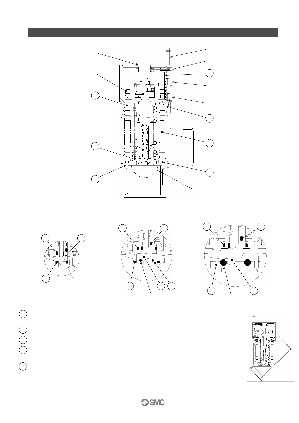
4. Construction
Adjustment nut (knurled outside)
for initial exhausting
Auto switch (option)
Adjustment nut holding screw
Magnet (option)
Bellows holder
(material: SUS304)
12
(material: SUS304)
Valve M
8
Body
(material: A6063)
7
Initial pumping valve (Enlarged view)
Bonnet assembly
1
(maintenance part)
Pilot port S
(For initial pumping valve)
Pilot port M
(For main pumping valve)
External seal
3
(maintenance part)
Bellows
11
(material: SUS316L)
Valve seal
2
(maintenance part)
Initial pumping valve (Refer to enlarged view)
10
5
XMD/XYD-25
Needle seat
(Material SUS304)
S valve assembly (Maintenance part)
4
(Material SUS304 + Seal material)
Initial pumping valve seal (Maintenance part)
5
Fixing ring
6
O-ring for sliding of S valve
9
(material:
SUS304)
10
S valve
(material:
FKM)
Note 2
Note 1
6
10
S valve seal O ring
XMD/XYD-40,XMD/XYD-50
Note1)
the whole assembly.
Note2)
The material of the O ring for sliding of S
is FKM. This cannot be changed.
Note3)
are the same except the Body shape.
6
4
4
S valve seal O ring
XMD/XYD-63,XMD/XYD-80
10
- 8 -
XYC series / Straight Valve
XL-OMP0003-A
Page 10

5. Operation
5-1. Adjusting the opening of the valve for initial pumping
Adjust the initial pumping amount with no air pressure to the pilot port S before using. Initial flow
is reduced by turning the adjustment nut clockwise. It is increased by turning it counterclockwise.
The location where the nut gently stops during rotation clockwise and counterclockwise indicates
the initial flow zero and the maximum flow. If the nut is rotated too much, it may damage the nut.
The adjustment nut shall be operated by hand. Do not use any tool. If the rotation of the
adjustment nut feels heavy, please refer to the following items.
The adjustment nut is fully closed when the completed product is shipped. The nut is fully open
when the bonnet assembly (maintenance part) is shipped. Use caution.
5-2. Fixing adjustment nuts
The adjustment nut does not rotate during the operation of the valve. It can be fixed to prevent
incorrect operation, if required. If the adjustment nut is fixed after adjusting the initial flow, tighten
the adjustment nut set screw to the tightening torque shown in the table below. When loosening
the set screw, loosen until it stops gently. Do not remove the adjustment nut set screw.
The adjustment nut is not fixed when the product is shipped. If the rotation of the adjustment nut
feels heavy, loosen the adjustment nut set screw.
Adjustment nut tightening torque
XMD/XYD-25
Model
Tightening torque 0.08 N・m or less 0.3 N・m or less
XMD/XYD-40
XMD/XYD-50
XMD/XYD-63
XMD/XYD-80
5-3. Opening the valve (s valve) for initial pumping
When the air pressure is applied to the pilot port S, the S valve will release from the S valve seal
assembly and open to the adjusted opening.
5-4. Opening the valve (valve M) for main pumping
When the air pressure is applied to the pilot port M, the valve will release from the body seat
and fully open. It operates even when air pressure is not applied to the pilot port S.
5-5. Closing the valve for initial pumping and main pumping
When the air pressure is released from the pilot port S and M, S and M valve will return and
start sealing.
- 9 -
XL-OMP0003-A
Page 11

φ
φ
φ
φ
φ
φ
(K
Flange
)
(KF
Flange
)
6. Dimensions
C
Model A B C D Fn Fd Fc G H J KK P.C.D. L1
XMD-25 50 123 48 1 40 - - 26 41 16 7.5 - -
XMD-40
XMD-50
XMD-63
XMD-80
65 170 66 2 55 - 70 41 63 20 15 P.C.D 58.7
70 183 79 2 75 - - 52 68 20 17.5
88 217 100
90 256 117
Model A B C D E Fn Fd G H J K
XYD-25 100.2 86.7 48 1 23.5
XYD-40 130 114 66 2 38 55 - 41 84 20 15
XYD-50 178 128 79 2 53 75 - 52 95 20 17.5
XYD-63 209 163 100 3 61 87 95 70 121 20 19.5
XYD-80 268 193 117 3 80 114 110 83 144 20 26.5
C
D
Fn
(KF
Flange
)
K
B
A
A
3 87 95 114 70 72 20 19.5 P.C.D 92.1
3 114 110
D
C
K
J
45°
H
Fd
(K
Flange
)
- 83 98 20 26.5
C
B
E
40 - 26 66 16 7.5
Fc
(CF
J
H
G
G
A
Flange
)
φFd
L1
L2
(φFc)
φFn
- -
- -
Unit: mm
Unit: mm
L2
6xφ6.6
8xφ 8.4
- 10 -
XL-OMP0003-A
Page 12

7. Guaranteed term and guaranteed range
The guaranteed period covers the period which finishes the earliest among 2 million operating
cycles [with our durability test conditions], 18 months after shipping from us, and 12 months after
starting the use of the product at your place or your customer’s place.
If the specification is not kept, or any non-conformance derived from mounting or replace of a
device, an assembly, or an O-ring at your place occurs, the guarantee cannot be applied.
Note: The product durability is varied depending on the operating conditions (such as a use with
large flow rate).
If any failure occurs due to our fault during the guaranteed period, we will guarantee the
non-conformance by delivering a substitute in the worst case. However, responsibility of any
damage which is led by the product failure is not taken by us.
Result of durability test (with the circuit
shown on the right)
Internal/ external leakage and operation were
checked by opening and closing a valve in
internally evacuated condition at ordinary
temperature (room temperature).
It was confirmed that this product satisfied the
specification up to 2 million cycles.
The test was performed with FKM, the standard
sealing material.
Endurance test conditions
<Reference>
The pumping direction is not limited, but if the pumping creates a flow stream, the durability of the
product could be impaired.
Therefore, the pumping direction shown on the right figure (bellows side pumping) is recommended.
Also, the operating conditions should be checked beforehand because it affects the life.
ブランクフランジ
耐久試験条件
Blank flange
ブランクフランジ
試験品姿勢:横向き
Test piece posture : lateral
1~10 Pa
真空ポンプ
Vacuum Pump
Valve side
Valve side
バルブ側
Bellows side
ベローズ側
Chamber
Recommended direction of exhaust
Bellows side
Vacuum pump
真空ポンプ
チャンバ
Chamber
推奨排気方向
Vacuum pump
Recommended direction of exhaust
- 11 -
XL-OMP0003-A
Page 13

8. Parts Replacement Procedure
8-1. Precautions
Be sure to follow [1. Precautions 1] when disassembling the product for maintenance. Along
with the precautions above, comply with the following precautions too.
Warning
• If it is expected that product materials may get stuck to the product, ensure safety is
assured before handling. It is recommended to wear gloves and a mask.
• Pay attention to the handling of components according to the procedure in the next item
onwards. Do not apply excessive force or impact. This will not only damage the product
but also decrease its performance and life expectancy.
• It is not possible to disassemble the bonnet assembly of this product. If the components
and assembly are damaged, or damage is expected, exchange the bonnet assembly
itself.
• Do not disassemble the parts that are not explained in this operation manual. The
performance and life may decrease. Also, it may cause danger.
- 12 -
XL-OMP0003-A
Page 14

S valve seal
Mounting surface of
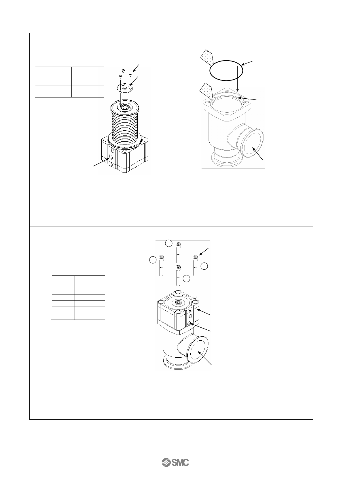
8-2. Disassembly procedure
Step 1 Step 2
3
1
4
Bolt b
2
Bonnet assembly
Pilot port M
O-ring
Bolt c
assembly
Body
Apply 0.2MPa of air pressure to the pilot port M. Loosen
bolt b in numerical order to disassemble the body and
the bonnet assembly.
Step 3 Step 4
O-ring
Bottom surface of
the groove to
discharge gas.
Pilot port S
Apply 0.3MPa of air pressure to the pilot port S. Loosen
bolt c to remove S valve seal assembly. Initial pumping
valve seal O ring is removed from 25, 40 and 50.
O ring
O ring
Remove the O ring from the groove for discharging gas
using a tool (plastic) whose height is the same as the
groove for discharging gas. <Take care not to damage
the O ring groove>
Body
Remove the external seal O ring from the body
<Take care to prevent the mounting surface of O ring
from being damaged>
- 13 -
XL-OMP0003-A
Page 15

8-3. Assembly Procedure
Step 1 Step 2 Step 3
O ring groove
Clean cloth
Ethanol
Assemble parts eliminating dust.
Wipe off dust with a clean cloth
soaked with ethanol. Blow parts
with clean air if necessary. <Ensure
there is no fiber or dust>
M valve
Eliminate the dust of O ring groove
of pilot valve M.
Step 4 Step 5
2
4
O ring
Wipe off the dust on the valve seal
O ring surface. Place the O ring on
the O ring groove. Press the
O-ring into the groove in numerical
order (press diagonally) to fit the
O-ring into the groove. Take care
not to twist the O ring.
<Use dust-free gloves>
O ring
3
1
S valve
M valve
Wipe off the dust of the S valve and around it.
Needle
seat
(XLD-25)
S valve seal
assembly
(XLD-63,80)
Remove dust from the needle seat or S valve seal
assembly. For size 25, 40 and 50, remove the dust from
the initial pumping valve seal O ring. Mount the needle
seat or S valve seal assembly.
S valve seal assembly
(XLD-40,50)
- 14 -
XL-OMP0003-A
Page 16
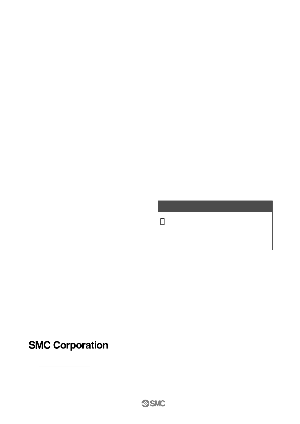
Tightening torque of bolt C
Step 6 Step 7
N・m
Model
X*D-25 0.36±0.1
Other than
X*D-25
Apply 0.3MPa of air pressure to the pilot port S. Place
the needle seat or S valve seal assembly, and tighten
bolt c to fix them. When tightening bolt c, first tighten
manually until the O ring is compressed, then perform
extra tightening.
Tightening
torque
0.63±0.1
Pilot port S
Bolt C
S valve seal
Ass'y or
Needle seat
O ring
Mounting surface of
O ring
Body
Wipe off the dust from the external seal O ring surface
and the mounting surface of the body O ring. Place the
O ring on the O ring mounting surface.
Step 8
Tightening torque of
bolt b
N・m
Valve
Size
X*D-25
-40
-50
-63
-80
Tightening
Torque
1.5
2.5
6
6
15
3
1
4
Bolt b
2
Bonnet assembly
Pilot port M
Body
Apply 0.2MPa of air pressure to the pilot port M (for main pumping). Tighten bolt b
in numerical order to assemble the body and the bonnet assembly. When
tightening bolt b, tighten manually until the O ring is compressed, then perform
extra tightening in diagonal order.
- 15 -
XL-OMP0003-A
Page 17
Revision history
A Limited warranty and Disclaimer Ro
1st Printing :PV
4-14-1, Sotokanda, Chiyoda-ku, Tokyo 101-0021 JAPAN
Tel: + 81 3 5207 8249 Fax: +81 3 5298 5362
URL http://www.smcworld.com
Specifications are subject to change without prior notice and any obligation on the part of the manufacturer.
Note:
© 2012 SMC Corporation All Rights Reserved
- 16 -
XL-OMP0003-A
 Loading...