

Page 1

EZ Connect™g
2.4GHz 802.11g Wireless USB2.0 Adapter
SMCWUSB-G2
Page 2

LIMITED WARRANTY
Limited Warranty S tatement: SMC Networks, Inc. (“SMC”) warrants its products to be free
from defects in workmanship and materials, under normal use and service, for the
applicable warranty te rm. All SMC product s carry a st andard 90-day limi ted warr anty from
the date of purchase from SMC or its Authorized Reseller. SMC may , at its own discretion,
repair or replace any product not operating as warranted with a similar or functionally
equivalent product, during t he applic abl e wa rranty te rm. SMC will end eav or to rep air or
replace any product returned under warranty within 30 days of receipt of the product. The
standard limited warranty can be upgraded to a Limited Lifetime* warranty by registering
new products within 30 days of purchase from SMC or its Authorized Reseller .
Registration can be accomplished via the enclosed product registration card or online via
the SMC website. Failure to register will not affect the standard limited warranty. The
Limited Lifetime warranty covers a product during the Life of that Product, which is defined
as the period of time during which the product is an “Active” SMC product. A product is
considered to be “Active” while it is listed on the current SMC price list. As new
technologies emerge, older technol ogies become obs olete and SMC will, a t it s disc retion,
replace an older product in its product line with one that incorporates these newer
technologies. At that point, the obsolete product is discontinued and is no longer an
“Active” SMC product. A list of discontinued products with their respective dates of
discontinuance can be found at:
http://www.smc.com/index.cfm? ac tion=customer_service_warranty.
All products t h a t a r e replaced become the property of SMC. Replacemen t p roducts may
be either new or reconditioned. Any replaced or repaired product carries either a 30-day
limited warranty or the remainder of the initial warranty, whichever is longer. SMC is not
responsible for any c us tom software or firmware, configuration inf orm a tion , o r m emory
data of Customer contained in, stored on, or integrated with any products returned to SMC
pursuant to any warranty. Products returned to SMC should have any customer-installed
accessory or add-on components, such as expansion modules, removed prior to returning
the product for replacement. SMC is not resp onsi ble f or thes e items if they a re retu rned
with the product. Cust omers must contact SMC fo r a Return Material Authorization
number prior to returning any product to SMC. Proof of purchase may be required. Any
product returned to SMC without a valid Return Material Authorization (RMA) number
clearly marked on the outside of the package will be returned to customer at customer’s
expense. For warranty claims within North America, please call our toll-free customer
support number at (800) 762-4968. Customers are responsible for all shipping charges
from their facility to SMC. SMC is responsible for return shipping charges from SMC to
customer.
i
Page 3

WARRANTIE S EXCLUSIVE: IF AN SMC PRODUCT DOES NOT OPERATE A S
WARRANTE D ABOVE, CUSTOMER’S SOLE REMEDY SHAL L BE REPAIR OR
REPLACEMENT OF THE PRODUCT IN QUESTION, AT SMC’S OPTION. THE
FOREGOING W ARRA NT IES AND REMEDIES ARE EXC LUSIV E AND ARE IN LIEU OF
ALL OTHER WARRANTIES OR CONDITIONS, EXPRESS OR IMPLIED, EITHER IN
FACT OR BY OPERA TION OF LAW, STATUTORY OR OTHERWISE, INCLUDING
WARRANTIES OR CONDITIONS OF MERCHANT ABILITY AND FITNESS FOR A
P AR TICULAR PURPOSE. SMC NEITHER ASSUM ES NOR AUTHOR IZES AN Y OTHER
PERSON TO ASSUME FOR IT ANY OTHER LIABILITY IN CONNECTION WITH THE
SALE, INSTALLATION, MAINTENANCE OR USE OF ITS PRODUCTS. SMC SHALL
NOT BE LIABLE UNDER THIS WARRANTY IF ITS TESTING AND EXAM INATION
DISCLOSE THE ALLEGED DEFECT IN THE PRODUCT DOES NOT EXIST OR W AS
CAUSED BY
CUSTOMER’S OR ANY THIRD PERSON’S MISUSE, NEGLECT, IMPROPER
INST ALLATION OR TESTING, UNAUTHORIZED ATTEMPTS TO REPAIR, OR ANY
OTHER CAUSE BEYOND THE RANGE OF THE INTENDED USE, OR BY ACCIDENT,
FIRE, LIGHTNING, OR OTHER HAZARD.
LIMITATION OF LIABILITY: IN NO EVENT, WHETHER BASED IN CONTRACT OR
TORT (INCLU DING NEGLIGEN CE), SH ALL SMC BE LIABLE FOR INCIDENTAL,
CONSEQUENTIAL, INDIRECT, SPECIAL, OR PUNITIVE DAMAGES OF ANY KIND, OR
FOR LOSS OF REVENUE, LOSS OF BUSINESS, OR OTHER FINANCIAL LOSS
ARISING OUT OF OR IN CONNECTION WITH THE SALE, INSTALLA TION,
MAINTENANCE, USE, PERFORMANCE, FAILURE, OR INTERRUPTION OF ITS
PRODUCTS, EVEN IF SMC OR ITS AUTHORIZED RESELLER HAS BEEN ADVISED
OF THE POSSIBILITY OF SUCH DAMAGES. SOME STATES DO NOT ALLOW THE
EXCLUSION OF IMPLIED WARRANTIES OR THE LIMITATION OF I NCIDENTAL OR
CONSEQUENTIAL DAMAGES FOR CONSUMER PRODUC TS, SO THE ABOVE
LIMITATIONS AND EXCLUSIONS MAY NOT APPLY TO YOU. THIS WARRANTY GIVES
YOU SPECIFIC LEGAL
RIGHTS, WHICH MAY VARY FROM STATE TO ST ATE. NOTHING IN THIS WARRANTY
SHALL BE TAKEN TO AFFECT YOUR STATUTOR Y RIGHTS.
* SMC will provide warranty serv ice fo r one year follo wing dis con tin uanc e fr om the activ e
SMC price list. Under the limited lifetime warranty, internal and external power supplies,
fans,
and cables are covered by a standard one-year warranty from date of purchase.
SMC Networks, Inc.
20 Mason
Irvine, CA 92618
ii
Page 4

Compliances
Federal Communication Commission Interference Statement
This equipment has been teste d an d fo und to com pl y with the limi t s for a Class B digital
device, pursuant to Part 15 of the FCC Rules. These limits are designed to provide
reasonable protection agai ns t har mful in terf erence in a residential install ati o n. T his
equipment generates, uses and can radiate radio frequency energy and, if not installed
and used in accordance with the instructions, may cause harmful interference to radio
communications. However, there is no guarantee that interference will not occur in a
particular installation. If this equipment does cause harmful interference to radio or
television reception, which can be determined by turning the equipment off and on, the
user is encouraged to try to correct the interference by one or more of the following
measures:
• Reorient or relocate the receiving antenna.
• Increase the distance between the equipment and receiver.
• Connect the equipment int o an outlet on a circuit di fferen t from that to whic h the receiver
is connected.
• Consult the dealer or an exp eri e nced radio /TV technic i an for h elp .
FCC Caution: To assure continued compliance, (example - use only shielded interface
cables when connecting to computer or peripheral devices) any changes or modifications
not expressly approv e d b y the party responsi ble for compliance coul d v oid the user’s
authority to operate this equipment.
This device complies wi th P art 15 of the FCC Rules. O p eration is subject to the following
two conditions: (1) This device may not cause harmful interference, and (2) this device
must accept any interference received, incl uding interference that m ay ca use u n desired
operation.
IMPORTANT NOTE
FCC Radiation Exposure Statement:
This equipment complies with FCC radi ati on expos ur e limit s set fort h for an unc ontroll ed
environment. This transmitter must not be co-located or operating in conjunction with any
other antenna or transmitter.
iii
Page 5

CE Mark Declaratio n of Conformance for EMI and Safety (EEC)
This device complies with the ess entia l requi rem ent s of the R&TTE Direc tive 1 999 /5/EC .
The following references hav e been ap pli ed in order to pr ov e presump ti on o f compli a nc e
with the R&TTE Directive 1999/5/EC:
• EN 300 328
• EN 301 489-1
• EN 301 489-17
• EN 60950-1
A copy of the CE Declaration of Conformity is available for download at:
http://www.smc.com
Intended for indoor use in the following countries:
AT, BE, CZ, CY, DK, EE, FI, FR, DE, GR, HU, IS, IE, IT, LV, LT, LU, MT, NL, NO, PL,
PT, SI, SK, ES, SE, CH, UK.
iv
Page 6

Table of Contents
Package Contents..............................................................................................................1
Chapter 1 Introduction.......................................................................................................2
1.1 Key Features..................................................................................................2
1.2 LED Status......................................................................................................2
1.3 System Requirements ....................................................................................2
1.4 Wireless LAN Networking.............. .................................................................3
Chapter 2 Installation Guide..........................................................................................6
2.1 Before You Begin............................................................................................6
2.2 Installing the Drivers.......................................................................................6
Chapter 3 Uninstall Guide ........................................................................................... 11
3.1 Through Control Panel.................................................................................. 11
3.2 Through Programs Menu............... .................... .......... .......... .......... .......... ...12
Chapter 4 Software Configuration..............................................................................15
4.1 Station Mode Configuration ..........................................................................15
4.1.1 More Setting.........................................................................................15
4.1.1.1 General Connection Setting..........................................................15
4.1.1.2 WEP Encryption............................................................................19
4.1.1.3 WP A/WP A2 Authentication with TKIP/AES Encryption..................20
4.1.1.4 WP A-PSK Authentication...............................................................23
4.1.1.5 Profiles ..........................................................................................23
4.1.1.6 Advanced Settings ........................................................................24
Chapter 5 Example configuration.................................... .......... .......... .................... ...26
5.1 Configuration of WEP Encryption.................................................................26
Appendix A: Glossary......................................................................................................28
Appendix B: Specifications.......................................................................................... ...30
v
Page 7

Package Contents
Open the package carefully, and make sure that none of the items listed below are missing:
• EZ Connect™ g 802.11g Wireless USB2.0 Adapter (SMCWUSB-G2)
• EZ Installation Wizard & Documentation CD
• Quick Installation Guide
• Warranty Information Card
1
Page 8

Chapter 1 Introduction
The SMCWUSB-G2 is a USB 2.0 pen-size wireless adapter supporting IEEE 802.11b/g 2.4GHz
radio operation. It provides high-speed wireless connection with data rate up to 54Mbps.
Additionally, wireless roaming allows the user to move among different AP without losing the
current connection. The adapter provides excellent security features including WPA and WPA2.
Featuring high performance transmission rates, simple installation and adaptability, as well as
strong security the SMCWUSB-G2 is the perfect solution for small office and home needs.
1.1 Key Features
• Complies with IEEE802.11b and IEEE 802.11g standards.
• Wireless speeds up to 54Mbps
•
WEP 64-/128-Bit, WPA & WPA2 wireless encryption
• High speed USB 2.0 interface
• Supports Windows 98, ME, 2000, XP and Vista
• Simulated AP Mode for supporting PSP connection
• WLAN management utility
EZ Installation Wizard for easy installation
•
1.2 LED Status
The following table describes the LED behavior:
COLOR STATUS DESCRIPTION
OFF No power
Green
ON Wireless connected without data traffic
Blinking Wireless connected with data traffic
1.3 System Requirements
The following are the minimum system requirements in order to install and use the
SMCWUSB-G2:
• 2.4 GHz 802.11b/g wireless network
• Microsoft Windows 98SE, ME, 2000, XP or Vista
• A Notebook or Desktop computer with:
o 300MHz CPU or above
o Available USB2.0 port
o 20MB of available hard disk space
o CD-ROM drive
2
Page 9
1.4 Wireless LAN Networking
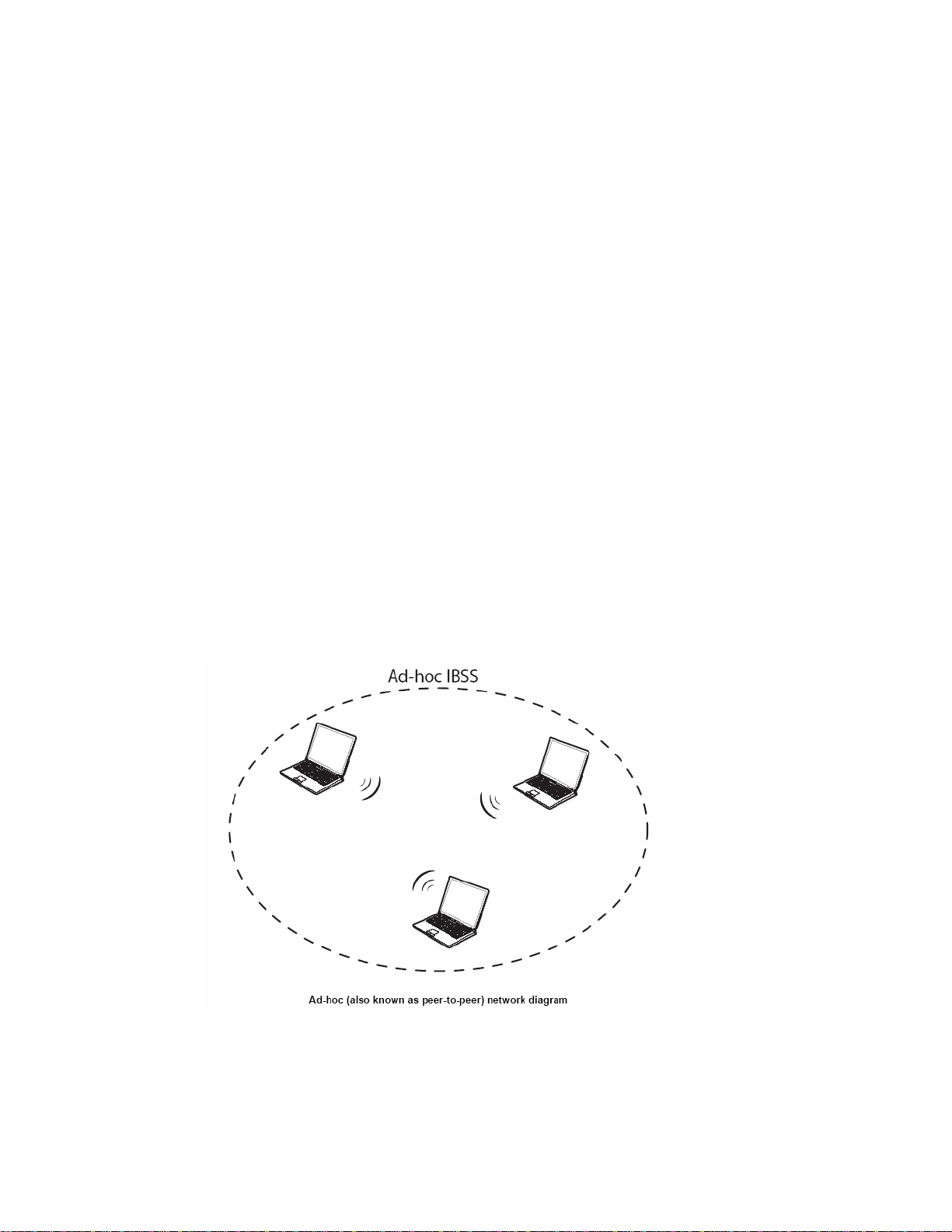
Wireless LAN networking works in either of the two modes: ad-hoc and infrastructure. In
infrastructure mode, wireless devices communicate to a wired LAN via access points. Each
access po int and its wireless devices are known as a Basic Service Set (BSS). An Extended
Service Set (ESS) is two or more BSSs in the same subnet. In ad hoc mode (also known as
peer-to-peer mode), wireless devices communicate with each other directly and do not use an
access point. This is an Independent BSS (IBSS).
To connect to a wired network within a coverage area using access points, set the adapter
operation mode to Infrastructure (BSS). To set up an independent wireless workgroup without
an access point, use Ad-hoc (IBSS) mode.
A
D-HOC (IBSS) NETWORK
Ad-hoc mode does not require an access point or a wired network. Two or more wireless
statio ns communica te directly to eac h other. An ad-hoc network may sometimes be referred to
as an Independent Basic Service Set (IBSS).
To set up an ad-hoc network, configure all the stations in ad-hoc mode. Use the same SSID
and channel for each.
3
Page 10
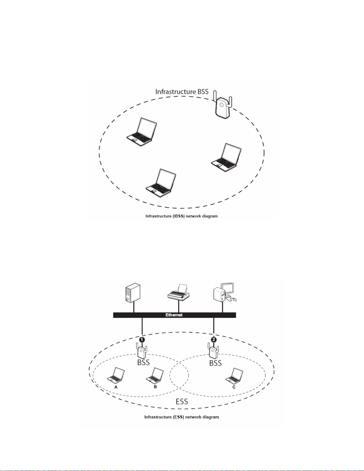
When a number of wireless stations are connected u sing a single access point, you have a
Basic Service Set (BSS).
In the ESS diagram below, communication is done through the access points, which relay
data packets to other wireless stations or devices connected to the wired network. Wireless
stations can then access resources, such as a printer, on the wired network.
4
Page 11
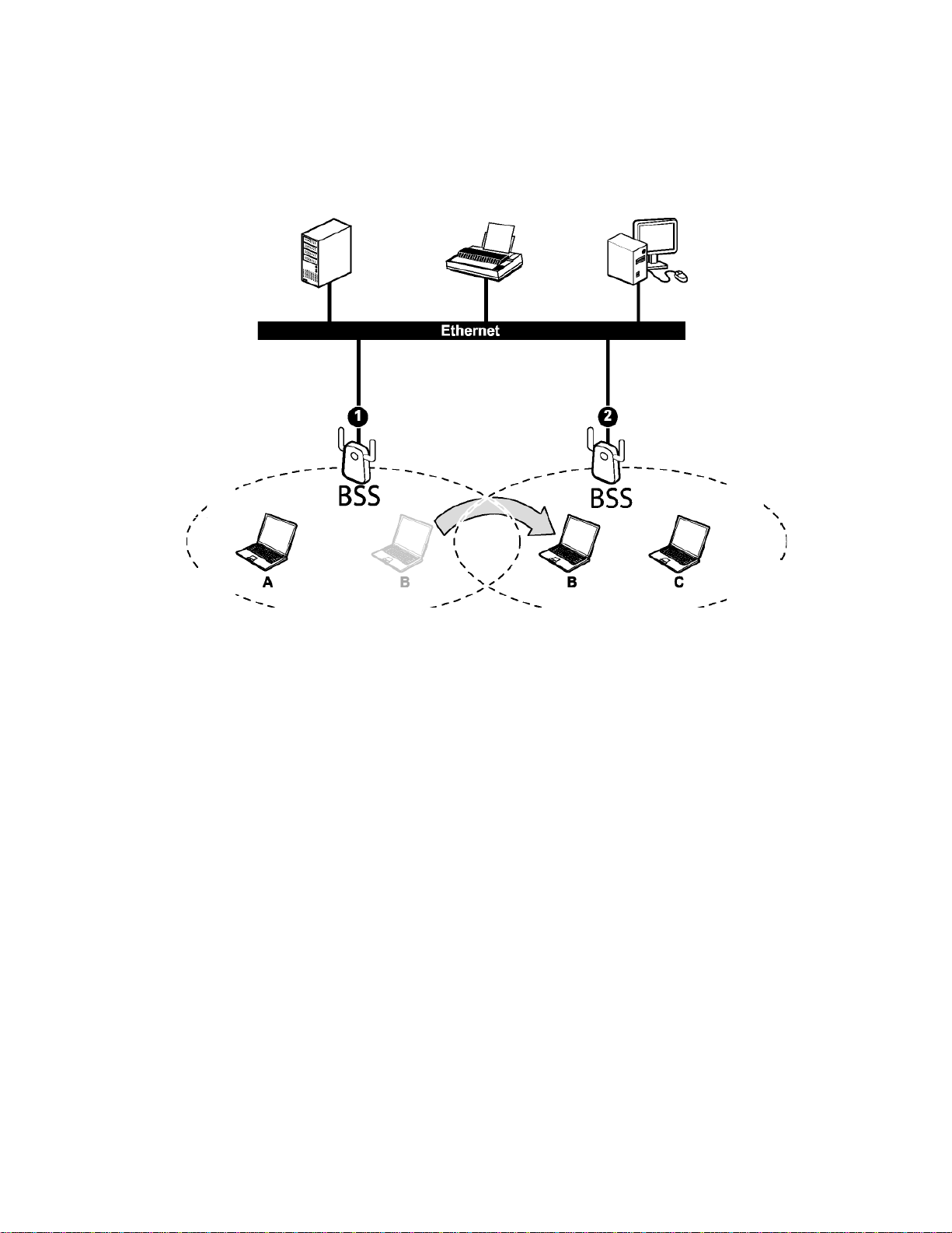
In an ESS environment, users are able to move from one access point to another without
losing the connection. In the diagram below, when the user moves from BSS (1) to BSS (2)
the adapter automatically switches to the channel used in BSS (2).
Roaming in an ESS network diagram
5
Page 12
Chapter 2 Installation Guide
2.1 Before You Begin
Before installing the new drivers of your SMCWUSB-G2 please close all programs. During
the installation, Windows may ne ed to co py systems fil es from its i nstallati on CD. T herefore,
you may need a copy of the Windows installation CD at hand before installing the drivers.
2.2 Installing the Drivers
Follow the steps below in order to install the SMCWUSB-G2 drivers:
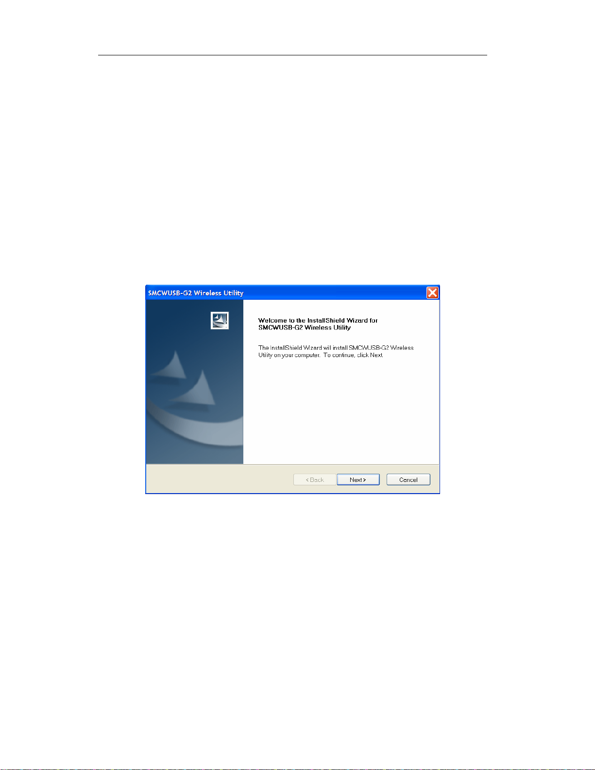
1) Insert the EZ Installation & Docum entation CD into your CD-ROM drive. The CD will
auto-run. Click
You will see the Install Shield Wizard, as shown below.
[Install Driver/Utility] to begin installation.
Figure 2-1 Install driver wizard
2) Click on the [Next] button to continue.
3) Select the location where you would like the driver installed. Click on the [Browse]
button to change the directory, or click on the [Next] button to continue using the
default directory.
6
Page 13

Figure 2-2 Install Shield—Choose Destination Location
Wait a few moments until the files are copied to the computer.
Figure 2-3 Install Shield—Setup Status
4) The first part of the installation is complete. Click the [Finish] button.
7
Page 14

Figure 2-4 Utility Installation Complete
5) Now insert the SMCWUSB-G2 into an available USB port of your computer.
Windows will automatically detect the device and display t he “Found New H ardware
Wizard”. Click [No, not this time], then click [Next] to continue.
Figure 2-5 Found New Hardware Wizard
6) Click [Install the Software Automatically (Recommended)], then click [Next] to
continue.
8
Page 15

Figure 2-6 Found New Hardware Wizard
7) A hardware installation warning may appear, click [Continue Anyway].
Figure 2-7 Hardware Installation Warning
8) Click [Finish] to complete driver and utility installation. Your SMCWUSB-G2 adapter
is now installed and ready to use.
9
Page 16

Figure 2-8 Driver Installation Complete
10
Page 17

Chapter 3 Uninstall Guide
If the device installation is unsuccessful for any reason, the best way to solve the problem
may be to completely uninstall the device and its utility and repeat the instal lation procedure
again. Hereby, customers can use one of the following two methods to uninstall the Drivers
and Utility.
3.1 Through Control Panel
Follow the steps below in order to uninstall the Drivers and Utility:
1. Click on Start > Settings > Control Panel > Add or Remove Programs
2. You will then see the following window. Select the SMCWUSB-G2 Wireless Utility and
then click on Remove.
Figure 3-1 Add or Remove Programs
3. Click on the OK button to confirm the Uninstalling process.
Figure 3-2 Confirm the Uninstalling process.
4. The process will then remove the SMCWUSB-G2 Wireless Utility and the drivers from
your computer. Click on the Finish button and then unplug the SMCWUSB-G2.
11
Page 18

Figure 3-3 Uninstalling process finished
3.2 Through Programs Menu
Follow the steps below in order to uninstall the Drivers and Utility:
1) Click on Start > Programs > SMC > Uninstall SMCWUSB-G2 Wireless Utility.
Figure 3-4 Uninstall from programs
12
Page 19

Then, process will go to Install Shield Wizard. The screen will pop up the following
conversation “Do you want to completely remove the selected application and all of
its features”
2) Click on the OK button to confirm the Uninstalling process.
Figure 3-5 Confirm the Uninstalling process.
The process will then remove SMCWUSB-G2 Wireless Utility and the drivers from your
computer.
Figure 3-6 Uninstalling SMCWUSB-G2 Wireless Utility and the drivers
¾ Click on the Finish button and then unplug the SMCWUSB-G2.
13
Page 20

Figure 3-7 Uninstalling process finished
14
Page 21

Chapter 4 Software Configuration
4.1 Station Mode Configuration
This chapter focuses on how to configure the device in Station mode (wireless LAN clien t)
¾ Current Network Informat ion
The Current Network Information screen displays the current status of the wireless radio
as a station.
Figure 4-1 Current Network Information
4.1.1 More Setting
4.1.1.1 General Connection Setting
The General Connection Setting allows you to configure the SSID, network type,
authentication, and encrypti on type .
15
Page 22

Figure 4-2 More setting
¾ You can click “Change” button to change general connection settings.
16
Page 23

Figure 4-3 More setting—Click Change
17
Page 24

Figure 4-4 More setting—WEP
¾ SSID: Enter the SSID of the network. The SSID is a unique name shared among all
points in your wireless network. The SSID must be identi cal for all poi nts in the n etwork,
and is case-sensitive. Place a check in the any box if you would like the device to
connect to the first available Access Point with the strongest signal.
¾ Network Type: Select a network type from the drop-down list.
¾ Infrastructure or Ad-hoc: If you select infrastructure, the device must be connected to
an Access Point. If you select ad-hoc, you may connect the device to another WLAN
client adapter (such as this one).
¾ Authentication: Select an authentication type from the drop down list. Options
available are: Auto, Open System, Shared Key, WPA, WPA-PSK, WPA2,
WPA2-PSK.
¾ Encryption: Select an encryption type from the drop-down list. Options available are:
Disable, WEP, TKIP, AES.
Note: Refer to the WEP encryption and WPA encryption sections in this chapter to
configure the security settings.
18
Page 25

4.1.1.2 WEP Encryption
You may select 64, 128 or 256 bit WEP (Wired Equivalent Privacy) key to encrypt data
(Default setting is Disable). WEP encrypts each frame transmitted from the radio using one
of the Keys from a panel. When you use WEP to communicate with the other wireless
clients, all the wireless devices in this network must have the same encryption key or pass
phrase.
¾ Authentication: Select Open System or Shared Key from the drop-down list. If you
are not sure what to choose, please select auto.
¾ Encryption: Select WEP from the drop-down list.
¾ Click on the WEP Encryption Key Setting button. You will see the figure below.
Figure 4-5 WEP Key Setting
¾ Key Length: Select an encryption key length: 64, 128 or 256 bit. The setting must be
the same as the Access Point.
¾ Default Key ID: Since you can specify up to 4 different WEP keys, select the WEP key
value that will be used for this network.
¾ Key Format: Select Hexadecimal or ASCII.
¾ Key Value #1 - #4: You may e nter up to 4 differe nt WEP keys. How ever, only that
WEP key will be used that is defined by the Default Key ID.
19
Page 26

Figure 4-6 Disabled WEP key settings
¾ The key is provided via IEEE 802.1X authentication: Place a check in this box is
IEEE 802.1X authentication is used. By selecting this option, the WEP key settings will
be disabled.
¾ Click on the Apply button, and then you can use the IEEE 802.1X authentication.
4.1.1.3 WPA/WPA2 Authentication with TKIP/AES Encryption
WPA (Wi-Fi Protected Access) was design ed to im pro ve upo n the s ecurity f eatur es of WEP
(Wired Equivalent Privacy). The technology is d esigned to work with existin g Wi-Fi pro ducts
that have been enabled with WEP. WPA provides improved data encryption through the
Temporal key Integrity Protocol (TKIP), which scrambles the keys using a hashing
algorithm and by adding an integrity checking feature which makes sure that keys haven’t
been tampered with.
20
Page 27

Figure 4-7 More settings—TKIP
¾ Authentication: Select WPA from the drop-down list.
¾ Encryption: Select TKIP or AES from the drop-down list.
¾ Click on the WPA Encryption Setting button.
In this section you can configure the settings for TLS or PEAP. TLS (Transport Layer
Security) is an IETF standardized authentication protocol that uses PKI (Public Key
Infrastructure) certificate-based authentication of both the client and authentication server.
21
Page 28

Figure 4-8 WPA setting
¾ Protocol: Select TLS from the drop-down list.
¾ User Name: Enter the user name that is used for authentication purposes .
¾ Passphrase: Enter a WPA passphrase. For ASCII text, enter 8-63 characters, for
hexadecimal enter 64 characters).
¾ Certificate: Make sure that you have downloaded and installed the certificate on the
computer. Then select the appropriate certificate from the drop-down list.
¾ Click on the Apply button to save the changes.
The PEAP authentication type is based on EAP TLS authentication, but uses a password
instead of a client certificate for authentication. PEAP uses a dynamic session-based WEP
key, which is derived from the device and RADIUS server, to encrypt data.
22
Page 29

4.1.1.4 WPA-PSK Authentication
Figure 4-9 WPA-PSK Aut hent icati o n
¾ Authentication: Select WPA-PSK from the drop-down list.
¾ Encryption: Select an encryption type from the drop-down list.
¾ Click on the Apply button to save the changes.
4.1.1.5 Profiles
Multiple profiles can be created for different Network Names (SSIDs) and security settings.
This allows a user to quickly associate with another network, instead of entering the
credentials each time.
23
Page 30

Figure 4-10 More Setting—Profile
¾ Profile Name: Displays the name of current profile. One device can have many profil es,
but only one profile can be loaded at a time.
¾ Load: Select a profile from the drop-down list and then click on the Load button.
¾ Save Current: Enter a new profile name and then click on the Save Current button to
save the profile.
¾ Delete: To delete an existing profile, select it from the drop-down list and then click on
the Delete button.
4.1.1.6 Advanced Settings
The Advanced Settings allows you to configure the user interface language, power
consumption, and threshold values.
24
Page 31

Figure 4-11 Adva nced Setti n g
¾ Power Consumption Setting: If your desktop or notebook is connected to external
power, select Continuous Access Mode (CAM), if your notebook is using a battery,
select Maximum Power-Saving Mode, or Fast Power-Saving Mode.
25
Page 32

Chapter 5 Example configuration
5.1 Configuration of WEP Encryption
Suppose you have an installed and using AP, the SSID is TEST and it adopts 64 bit WEP
encryption with the key “1111111111”.
To establish a connection with this AP, you should follow five steps below:
Double click “TEST” in available network ta skbar to connect this network.
Step 1:Double
click ”TEST” to
connect this
network.
Click “No” to continue.
Figure 5-1
Figure 5-2
Step 2:Click ”No ” to
continue.
26
Page 33

Figure 5-3
In WEP key setting dialogue box click “change" to continue our se tti ng .
¾ Key length: 64 bit
Step 3:Click
“Change”
¾ Default key ID:#1
¾ Key format:Hexadecimal
¾ Key value:enter “1111111111” in #1
Click the close button in top ri ght lef t of the scr een, and it will retur n to the scr een of wir eless
utility. Till now we have finished WEP encryption configuration.
Step 6:Click here.
Step 4:Set the options
as the picture show,
these are the same as
the Access Point.
Click the “
Figure 5-4
Step 5:Click “Apply”
to finish your settings.
”
27
Page 34

Appendix A: Glossary
¾ IEEE 802.11b - The IEEE 802.11b standard specifies a wireless networking at 11 Mbps
using direct-sequence spread-spectrum (DSSS) technology and operating in the
unlicensed radio spectrum at 2.4GHz, and WEP encryption for security. IEEE 802.11b
networks are also referred to as Wi-Fi networks.
¾ IEEE 802.11g - Specification for wireless networking at 54 Mbps using direct-sequence
spread-spectrum (DSSS) technology, using OFDM modulation and operating in the
unlicensed radio spectrum at 2.4GHz, and backward compatibility with IEEE 8021b
devices, and WEP encryption for security.
¾ Ad-hoc Netw ork - An ad-hoc network is a group of computers, each with a wireless
adapter, connected as an independent IEEE 802.11 wireless LAN. Ad-hoc wireless
computers operate on a peer-to-peer basis, communicating directly with each other
without the use of an access point. Ad-hoc mode is also referred to as an Independent
Basic Service Set (IBSS) or as peer-to-peer mode, and is useful at a departmental
scale or SOHO operation.
¾ Infrastructure Network - An infrastructure network is a group of computers or other
devices, each with a wireless adapter, connected as an IEEE 802.11 wireless LAN. In
infrastructure mode, the wireless devices communicate with each other and to a wired
network by first going through an access point. An infrastructure wireless network
connected to a wired network is referred to as a Basic Service Se t (BSS). A set of two or
more BSS in a single network is referred to as an Extended Service Set (ESS).
Infrastructure mode is useful at a corporation scale, or when it is necessary to connect
the wired and wireless networks.
¾ SSID - A Service Set Identification is a thirty-two character (maximum) alphanumeric
key identifying a wireless local area network. For the wireless devices in a network to
communicate with each other, all devices must be configured with the same SSID. This
is typically the configuration parameter for a wireless PC card. It corresponds to the
ESSID in the wireless Access Point and to the wireless network name.
¾ WEP (Wired Equivalent Privacy) - A data privacy mechanism based on a 64 bit or 128
bit or 256 bit shared key algorithm, as described in the IEEE 802. 11g st andard.
¾ Wi-Fi - A trade name for the IEEE 802.11b wireless networking standard, given by the
Wireless Ethernet Compa tibility Alliance (WECA, s ee http://www.wi-fi.net), an industry
standards group promoting interoperability among IEEE 802. 11b devi ce s.
¾ WLAN (Wireless Local Area Network) - A group of computers and associated devices
communicate with each other wirelessly, which network serving users are limited in a
local area.
¾ WPA (Wi-Fi Protected Access) -
Integrity Protocol) encryption, which can be used in conjunction with a RADIUS server.
¾ AP- Access Point
A wireless security protocol use TKIP (Temporal Key
28
Page 35

¾ PSK- Pre-Shared Key
¾ TKIP- Temporal Key Integrity Protocol
¾ AES- Advanced Encryption Standard
¾ TLS- Transport Layer Security
¾ TTLS- Tunnel Transport Layer Security
¾ PEAP- Protected Extended Authentication Protocol
¾ RADIUS- Remote Authentication Dial In User Service
29
Page 36

Appendix B: Specifications
Normal
Interface
Standards
Operating System
Transmission
Distance
A-type USB 2.0 Connector
IEEE 802.1b; IEEE 802.1g
Windows 98, ME, 2000, XP, Vista
In door up to 100m, out door up to 300m (It is limited to the
environment).
Radio Data Rate
Modulation
Media Access
Protocol
Transmit Power
Data Security
Frequency
Spread Spectrum
Safety & Emissions
Operating Temp
Storage Temp
54/48/36/24/18/12/9/6 Mbps 11g OFDM,11/5.5/3/2/1 Mbps 11b
DSSS,(Auto Rate Sensing)
11g OFDM , 11b CCK/DSSS
CSMA/CA with ACK
15dBm (Typical)
WPA; 64/128/256 bit WEP; TKIP/AES ; IEEE802.1X authentication
2.4~2.4835 GHz
Direct Sequence Spread Spectrum (DSSS)
FCC, CE
Physical Environmental
0℃~55
-40℃~70℃ (-40℉~158℉)
℃ (32℉~104℉)
Humidity
Dimensions
(W×D×H)
5%~90% RH, Non-condensing
3.4×1.0×0.5 inch (85.7×25.9×11.8 mm)
30
Page 37

SMCWUSB-G2
SMCWBR11-G
 Loading...