

Page 1

EZ Connect g
802.11g Wireless 4-port Broadband Router
SMCWBR14-G3
Page 2

LIMITED WARRANTY
Limited Warranty Statement: SMC Networks, Inc. (“SMC”) warrants its products to be
free from defects in workmanship and materials, under normal use and service, for the
applicable warranty term. All SMC products carry a standard 90-day limited warranty
from the date of purchase from SMC or its Authorized Reseller. SMC may, at its own
discretion, repair or replace any product not operating as warranted with a similar or
functionally equivalent product, during the applicable warranty term. SMC will endeavor
to repair or replace any product returned under warranty within 30 days of receipt of the
product. The standard limited warranty can be upgraded to a Limited Lifetime* warranty
by registering new products within 30 days of purchase from SMC or its Authorized
Reseller. Registration can be accomplished via the enclosed product registration card or
online via the SMC website. Failure to register will not affect the standard limited
warranty. The Limited Lifetime warranty covers a product during the Life of that Product,
which is defined as the period of time during which the product is an “Active” SMC
product. A product is considered to be “Active” while it is listed on the current SMC price
list. As new technologies emerge, older technologies become obsolete and SMC will, at
its discretion, replace an older product in its product line with one that incorporates these
newer technologies. At that point, the obsolete product is discontinued and is no longer
an “Active” SMC product. A list of discontinued products with their respective dates of
discontinuance can be found at:
http://www.smc.com/index.cfm?action=customer_service_warranty.
All products that are replaced become the property of SMC. Replacement products may
be either new or reconditioned. Any replaced or repaired product carries either a 30-day
limited warranty or the remainder of the initial warranty, whichever is longer. SMC is not
responsible for any custom software or firmware, configuration information, or memory
data of Customer contained in, stored on, or integrated with any products returned to
SMC pursuant to any warranty. Products returned to SMC should have any
customer-installed accessory or add-on components, such as expansion modules,
removed prior to returning the product for replacement. SMC is not responsible for these
items if they are returned with the product. Customers must contact SMC for a Return
Material Authorization number prior to returning any product to SMC. Proof of purchase
may be required. Any product returned to SMC without a valid Return Material
Authorization (RMA) number clearly marked on the outside of the package will be
returned to customer at customer’s expense. For warranty claims within North America,
please call our toll-free customer support number at (800) 762-4968. Customers are
responsible for all shipping charges from their facility to SMC. SMC is responsible for
return shipping charges from SMC to customer.
WARRANTIES EXCLUSIVE: IF AN SMC PRODUCT DOES NOT OPERATE AS
WARRANTED ABOVE, CUSTOMER’S SOLE REMEDY SHALL BE REPAIR OR
REPLACEMENT OF THE PRODUCT IN QUESTION, AT SMC’S OPTION. THE
FOREGOING WARRANTIES AND REMEDIES ARE EXCLUSIVE AND ARE IN LIEU
OF ALL OTHER WARRANTIES OR CONDITIONS, EXPRESS OR IMPLIED, EITHER
IN FACT OR BY OPERATION OF LAW, STATUTORY OR OTHERWISE, INCLUDING
Page 3

WARRANTIES OR CONDITIONS OF MERCHANTABILITY AND FITNESS FOR A
PARTICULAR PURPOSE. SMC NEITHER ASSUMES NOR AUTHORIZES ANY
OTHER PERSON TO ASSUME FOR IT ANY OTHER LIABILITY IN CONNECTION
WITH THE SALE, INSTALLATION, MAINTENANCE OR USE OF ITS PRODUCTS.
SMC SHALL NOT BE LIABLE UNDER THIS WARRANTY IF ITS TESTING AND
EXAMINATION DISCLOSE THE ALLEGED DEFECT IN THE PRODUCT DOES NOT
EXIST OR WAS CAUSED BY CUSTOMER’S OR ANY THIRD PERSON’S MISUSE,
NEGLECT, IMPROPER INSTALLATION OR TESTING, UNAUTHORIZED ATTEMPTS
TO REPAIR, OR ANY OTHER CAUSE BEYOND THE RANGE OF THE INTENDED
USE, OR BY ACCIDENT, FIRE, LIGHTNING, OR OTHER HAZARD.
LIMITATION OF LIABILITY: IN NO EVENT, WHETHER BASED IN CONTRACT OR
TORT (INCLUDING NEGLIGENCE), SHALL SMC BE LIABLE FOR INCIDENTAL,
CONSEQUENTIAL, INDIRECT, SPECIAL, OR PUNITIVE DAMAGES OF ANY KIND,
OR FOR LOSS OF REVENUE, LOSS OF BUSINESS, OR OTHER FINANCIAL LOSS
ARISING OUT OF OR IN CONNECTION WITH THE SALE, INSTALLATION,
MAINTENANCE, USE, PERFORMANCE, FAILURE, OR INTERRUPTION OF ITS
PRODUCTS, EVEN IF SMC OR ITS AUTHORIZED RESELLER HAS BEEN ADVISED
OF THE POSSIBILITY OF SUCH DAMAGES. SOME STATES DO NOT ALLOW THE
EXCLUSION OF IMPLIED WARRANTIES OR THE LIMITATION OF INCIDENTAL OR
CONSEQUENTIAL DAMAGES FOR CONSUMER PRODUCTS, SO THE ABOVE
LIMITATIONS AND EXCLUSIONS MAY NOT APPLY TO YOU. THIS WARRANTY
GIVES YOU SPECIFIC LEGAL RIGHTS, WHICH MAY VARY FROM STATE TO STATE.
NOTHING IN THIS WARRANTY SHALL BE TAKEN TO AFFECT YOUR STATUTORY
RIGHTS.
* SMC will provide warranty service for one year following discontinuance from the active
SMC price list. Under the limited lifetime warranty, internal and external power supplies,
fans, and cables are covered by a standard one-year warranty from date of purchase.
SMC Networks, Inc.
20 Mason
Irvine, CA 92618
Page 4

COMPLIANCES
Federal Communication Commission Interference Statement
This equipment has been tested and found to comply with the limits for a Class B digital
device, pursuant to Part 15 of the FCC Rules. These limits are designed to provide
reasonable protection against harmful interference in a residential installation. This
equipment generates, uses and can radiate radio frequency energy and, if not installed
and used in accordance with the instructions, may cause harmful interference to radio
communications. However, there is no guarantee that interference will not occur in a
particular installation. If this equipment does cause harmful interference to radio or
television reception, which can be determined by turning the equipment off and on, the
user is encouraged to try to correct the interference by one or more of the following
measures:
• Reorient or relocate the receiving antenna.
• Increase the distance between the equipment and receiver.
• Connect the equipment into an outlet on a circuit different from that to which the
receiver is connected.
• Consult the dealer or an experienced radio/TV technician for help.
FCC Caution: To assure continued compliance, (example - use only shielded interface
cables when connecting to computer or peripheral devices) any changes or
modifications not expressly approved by the party responsible for compliance could void
the user’s authority to operate this equipment.
This device complies with Part 15 of the FCC Rules. Operation is subject to the following
two conditions: (1) This device may not cause harmful interference, and (2) this device
must accept any interference received, including interference that may cause undesired
operation.
IMPORT ANT NOTE
FCC Radiation Exposure Statement:
This equipment complies with FCC radiation exposure limits set forth for an uncontrolled
environment. This transmitter must not be co-located or operating in conjunction with
any other antenna or transmitter.
Page 5
EC Declaration of Conformity
SMC contact for these products in Europe is:
SMC Networks Europe,
Edificio Conata II,
Calle Fructuos Gelabert 6-8, 2o, 4a,
08970 - Sant Joan Despi,
Barcelona, Spain.
Marking by the above symbol indicates compliance with the Essential Requirements of the
R&TTE Directive of the European Union (1999/5/EC). This equipment meets the following
conformance standards:
EN 300 328
EN 301 489
EN 60950-1
Council recommendation 1999/519/EC of 12 July 1999, limitations of exposure
of the general public to electromagnetic fields (0 Hz to 300 GHz)
[Czech] Společnost SMC Networks tímto prohlašuje, že toto rádiové zařízení LAN je ve shodě
se základními požadavky a dalšími příslušnými ustanoveními směrnice 1999/5/ES.
Oficiální ES prohlášení o shodě je uvedeno v příslušné části k produktu na webu
http://www.smc.com
[Danish] SMC Networks erklærer herved, at følgende Radio LAN-enhed overholder de
væsentlige krav og andre relevante bestemmelser i direktiv 1999/5/EF. Den officielle
EU-overensstemmelseserklæring er tilgængelig under det relevante produktafsnit på
følgende webadresse: http://www.smc.com
.
[German] Hiermit erklärt SMC Networks, dass sich dieses Wireless LAN Gerät in
Übereinstimmung mit den grundlegenden Anforderungen und den anderen relevanten
Vorschriften der Richtlinie 1999/5/EG befindet. Die offizielle EC-Declaration of
Conformity finden Sie im Internet unter http://www.smc.com unter der entsprechenden
Produktkategorie.
[Estonian] Käesolevaga kinnitab SMC Networks, et see Radio LAN seade vastab direktiivi
1995/5/EÜ põhinõuetele ja teistele asjakohastele sätetele. Ametliku EÜ
vastavusdeklaratsiooni leiate vastavast tootejaotisest aadressil http://www.smc.com
.
[English] Hereby, SMC Networks, declares that this Radio LAN device is in compliance with the
essential requirements and other relevant provisions of Directive 1999/5/EC. The official
EC-Declaration of Conformity can be found under the corresponding product section on
the web http://www.smc.com.
Page 6
[Spanish] Por medio de la presente SMC Networks declara que el Radio LAN device cumple con
los requisitos esenciales y cualesquiera otras disposiciones aplicables o exigibles de la
Directiva 1999/5/CE. The official EC-Declaration of Conformity can be found under the
corresponding product section on the web http://www.smc.com
[Greek] Με την παρούσα, η SMC Networks, δηλώνει ότι η συσκευή ασύρµατου τοπικού δικτύου
συµµορφώνεται µε τις ουσιώδεις απαιτήσεις και τις λοιπές σχετικές διατάξεις της
Οδηγίας 1999/5/EΚ. Η επίσηµη δήλωση συµµόρφωσης EΚ παρέχεται στην αντίστοιχη
ενότητα προϊόντων, στην ιστοσελίδα http://www.smc.com
.
[French] Par la présente SMC Networks déclare que l'appareil Radio LAN device est conforme
aux exigences essentielles et aux autres dispositions pertinentes de la directive
1999/5/CE. La déclaration de conformité officielle peut être trouvée sur notre site
internet http://www.smc.com dans la rubrique Produits.
[Italian] Con la presente SMC Networks dichiara che questo Radio LAN device è conforme ai
requisiti essenziali ed alle altre disposizioni pertinenti stabilite dalla direttiva 1999/5/CE.
La Dichiarazione di conformità CE ufficiale è disponibile nella sezione dedicata al
rispettivo prodotto sul sito Web http://www.smc.com
.
[Latvian] Ar šo SMC Networks deklarē, ka Radio LAN device atbilst Direktīvas 1999/5/EK
būtiskajām prasībām un citiem ar to saistītiem noteikumiem. Oficiālā EK atbilstības
deklarācija ir atrodama attiecīgā produkta sadaļā tīmeklī http://www.smc.com
.
[Lithuanian] Šiuo „SMC Networks“ deklaruoja, kad šis radijo LAN įrenginys atitinka esminius
reikalavimus ir kitas 1999/5/EB Direktyvos nuostatas. Oficialią jo EB atitikties
deklaraciją galima rasti atitinkamų gaminių skyriuje šiame tinklalapyje:
http://www.smc.com
.
[Dutch] Hierbij verklaart SMC Networks dat het toestel Radio LAN device in overeenstemming
is met de essentiële eisen en de andere relevante bepalingen van richtlijn 1999/5/EG.
Het officiële EC- gelijkvormigheidattest kan men vinden op de internetsite
http://www.smc.com onder de betrokken productcategorie.
[Maltese] B’dan, SMC Networks, tiddikjara li dan it-tagħmir LAN tar-Radju huwa konformi
mar-rekwiżiti essenzjali u dispożizzjonijiet rilevanti oħra ta’ Direttiva 1999/5/KE.
Id-Dikjarazzjoni ta’ Konformità uffiċjali tal-KE tinsab fit-taqsima korrispondenti fis-sit ta’
l-Internet http://www.smc.com
.
[Hungarian] Az SMC Networks kijelenti, hogy a Radio LAN eszköz megfelel a vonatkozó alapvető
követelményeknek és az 1999/5/EC irányelv egyéb előírásainak. A hivatalos EC
megfelelőségi nyilatkozat megtalálható a vonatkozó termék ismertetőjénél, a következő
címen: http://www.smc.com
[Polish] Firma SMC Networks niniejszym oświadcza, że urządzenie Radio LAN jest zgodne z
Page 7
zasadniczymi wymaganiami oraz pozostałymi stosownymi postanowieniami Dyrektywy
1999/5/EC. Oficjalna Deklaracja zgodności UE znajduje się w odpowiedniej sekcji
produktu w witrynie http://www.smc.com
.
[Portuguese] A SMC Networks declara que este dispositivo de LAN de Rádio está em conformidade
com os requisitos essenciais e com outras provisões relevantes da Directiva
1999/5/CE. A Declaração de Conformidade CE oficial encontra-se na secção
correspondente do produto na Web, http://www.smc.com
.
[Slovenian] Družba SMC Network izjavlja, da je naprava Radio LAN skladna z bistvenimi zahtevami
in drugimi ustreznimi predpisi direktive 1999/5/ES. Za uradno izjavo o skladnosti ES
glejte razdelek za ustrezni izdelek na spletni strani http://www.smc.com
.
[Slovak] Spoločnosť SMC Networks týmto vyhlasuje, že toto zariadenie Radio LAN spĺňa
základné požiadavky a ďalšie príslušné ustanovenia smernice 1999/5/ES. Oficiálne
prehlásenie ES o zhode je uvedené v sekcii príslušného produktu v lokalite
http://www.smc.com
.
[Finnish] SMC Networks vakuuttaa täten, että Radio LAN device -tyyppinen laite on direktiivin
1999/5/EY oleellisten vaatimusten ja sitä koskevien direktiivin muiden ehtojen
mukainen. EY:n virallinen vaatimustenmukaisuusvakuutus on tuotteen kohdalla
Web-sivustossa http://www.smc.com
.
[Swedish] Härmed intygar SMC Networks att denna Radio LAN-apparat uppfyller de väsentliga
egenskapskrav och övriga relevanta bestämmelser i direktiv 1999/5/EG. Den officiella
EG-försäkran om överensstämmelse finns under motsvarande produktavsnitt på
http://www.smc.com
.
[Icelandic] Hér með lýsir SMC Networks því yfir að þessi Radio LAN búnaður er í samræmi við
grunnkröfur og aðrar viðeigandi kröfur, sem gerðar eru í tilskipun 1999/5/EB. Opinberu
EB-samræmisyfirlýsinguna er að finna í viðeigandi hluta um þennan búnað á vefsetrinu
http://www.smc.com
.
[Norwegian] SMC Networks erklærer herved at Radio LAN-enheten er i samsvar med de
grunnleggende kravene og øvrige relevante krav i direktiv 1999/5/EF. Denne offisielle
EU-konformitetserklæringen finnes under korresponderende produktseksjon på
Internett: http://www.smc.com
.
Countries of Operation & Conditions of Use in EC/ EFTA member states
[English] This device is a 2.4 GHz wireless LAN transceiver, intended for indoor home and office
use in all notified EC and EFTA member states. In accordance with article 6.4 of the
R&TTE Directive 1999/5/EC the following EC/ EFTA member states have been notified:
Page 8

Austria, Belgium, Denmark, Finland, France, Germany, Italy, Luxembourg, Netherlands,
Norway, Spain, Sweden, Switzerland, United Kingdom, Portugal, Greece, Ireland,
Iceland. Requirements for outdoor operation, like license requirements and allowed
channels of operation apply in some countries. Please contact your local regulation
authority or SMC Networks for details on current restrictions for outdoor use.
[French]
Ce produit est un appareil radio LAN transceiver de 2.4 GHz destiné aux PME et à
l’utilisation domestique dans tous les pays certifiés conformes aux conditions de l’EU et
de l’EFTA. En accord avec l’article 6.4 de la R&TTE directive 1999/5/EC, the membres
de la EU et de l’EFTA sont les suivants : Autriche, Belgique, Danemark, finalnde,
France, Allemagne, Italie, Luxembourg, Pays-Bas, Norvège, Espagne, Suède, Suisse,
Royaume-Uni, Portugal, Grèce, Irelande, Icelande. Des conditions sont appliquées à
certains pays pour l’utilisation en extérieur, tels que des licences spécífiques et des
canaux d’opération. Veuillez contacter votre autorité locale ou SMC Networks pour plus
de détails quant aux restrictions actuelles concernant l’utilisation en extérieur.
[Dutch] Dit toestel is een 2.4 Ghz draadloze Lan transceiver, bestemd voor gebruik binnen huis
en kantoor in alle geïnformeerde lidstaten van de EC en de EFTA. In overeenstemming
met artikel 6.4 van de R&T TE Directive 1999/5/EC zijn de volgende EC/EFTA lidstaten
verwittigd: België, Denemarken, Duitsland, Finland, Frankrijk,Griekenland, Ierland,
IJsland, Italië, Luxemburg, Nederland, Noorwegen,Oostenrijk, Portugal, Spanje ,
Verenigd Koninkrijk, Zweden, Zwitserland. Benodigdheden voor gebruik buiten, zoals
gebruiksvergunningen en toegelaten werkkanalen zijn van toepassing in sommige
landen. Gelieve uw lokale instantie of SMC Networks te contacteren voor details op
huidige beperkingen voor gebruik in buitenlucht.
[Spanish] Este aparato es un transmisor inalámbrico de 2.4 GHz, previsto para el uso interior en
domicilios y Pymes en todos los Estados de la CE y la EFTA notificados. De acuerdo
con el artículo 6.4 de la Directiva R&TTE 1999/5/EC los siguientes estados de la CE y
de la EFTA han sido notificados: Austria, Bélgica, Dinamarca, Finlandia, Francia,
Alemania, Italia, Luxemburgo, Países Bajos, Noruega, España, Suecia, Suiza, Reino
Unido, Portugal, Grecia, Irlanda, Islandia. Los requisitos para su uso exterior, como
requerimiento de licencia y canales de operación permitidos se aplican en algunos
países. Por favor contacte la autoridad reguladora local o SMC Networks para más
detalles en relación con las restricciones actuales para uso exterior.
[German]
Dieses Wireless LAN Gerät arbeitet im 2.4 GHz Frequenzband und ist für den Einsatz
im Innenbereich in den benachrichtigten EC/ EFTA Mitgliedstaaten geeignet. In
Übereinstimmung mit Artikel 6.4 der R&TTE Direktive 1999/5/EC wurden folgende
Mitgliedstaaten benachrichtigt: Österreich, Belgien, Dänemark, Finland, Frankreich,
Deutschland, Italien, Luxemburg, Niederlande, Norwegen, Spanien, Schweden,
Schweiz, Großbritannien, Portugal, Griechenland, Irland, Island. Für den Einsatz im
Aussenbereich sind in einigen Ländern Lizenzen erforderlich oder die Anzahl der
Kanäle ist eingeschränkt. Bitte kontaktieren Sie Ihre Regulierungsbehörde oder SMC
Page 9

Networks für die aktuellen Einschränkungen beim Einsatz im Aussenbereich.
[Czech] Toto zařízení je přijímač a vysílač pro bezdrátové sítě LAN v pásmu 2,4 GHz, určený
pro použití v interiéru domácností a kanceláří ve všech členských zemích ES a ESVO,
kterým byl oznámen záměr uvést zařízení na trh. V souladu s čl. 6 odst. 4 směrnice
1999/5/ES o rádiových zařízeních a telekomunikačních koncových zařízeních byly
uvědoměny tyto členské země ES nebo ESVO: Belgie, Dánsko, Finsko, Francie, Irsko,
Island, Itálie, Lucembursko, Německo, Nizozemsko, Norsko, Portugalsko, Rakousko,
Řecko, Spojené království, Španělsko, Švédsko, Švýcarsko. Na použití ve venkovním
prostředí se v některých zemích vztahují určité požadavky, např. požadavky na licenci
nebo provoz v povolených kanálech. O omezení venkovního použití se informujte u
místních regulátorů nebo u společnosti SMC Networks.
[Danish] Enheden er en 2,4 GHz trådløs LAN-transceiver, beregnet til indendørs hjemme- og
kontorbrug i alle notificerede EU- og EFTA-medlemslande. I henhold til afsnit 6.4 i
R&TTE-direktivet 1999/5/EF er følgende EU-/EFTA-medlemslande notificeret: Østrig,
Belgien, Danmark, Finland, Frankrig, Tyskland, Grækenland, Island, Irland, Italien,
Luxembourg, Holland, Norge, Portugal, Spanien, Sverige, Schweiz og Storbritannien. I
visse lande gælder der krav vedrørende udendørs betjening af enheden, f.eks.
licenskrav og tilladte betjeningskanaler. Kontakt de lokale lovgivende myndigheder eller
SMC Networks for at få oplysninger om aktuelle begrænsninger vedrørende udendørs
betjening.
[Estonian] See seade on 2.4 GHz juhtmeta LAN vastuvõtu-saatejaam, mis on mõeldud kodus ja
kontoris kasutamiseks kõikides teavitatud EÜ ja Euroopa Vabakaubanduse
Assotsiatsiooni (EFTA) liikmesriikides. Vastavalt R&TTE direktiivi 1999/5/EÜ
paragrahvile 6.4 on teavitatud järgmisi EÜ/EFTA liikmesriike: Austriat, Belgiat, Taanit,
Soomet, Prantsusmaad, Saksamaad, Itaaliat, Luksemburgi, Hollandit, Norrat,
Hispaaniat, Rootsit, Šveitsi, Ühendkuningriiki, Portugali, Kreekat, Iirimaad, Islandi.
Mõningates riikides kehtivad väljas kasutamiseks nõuded, näiteks litsentsinõuded ja
lubatud töökanalid. Palun teavitage vastavat kohalikku ametkonda või ettevõtet SMC
Networks’i, kui soovite täpsemaid andmeid väljas kasutamisel kehtivate piirangute
kohta.
[Greek] Αυτή η συσκευή είναι ένας ασύρµατος ποµποδέκτης τοπικού δικτύου 2,4 GHz, που
προορίζεται για οικιακή και επαγγελµατική χρήση σε εσωτερικό χώρο, σε όλα τα
κράτη-µέλη της ΕΚ και της ΕΖΕΣ. Σύµφωνα µε το άρθρο 6.4 της Οδηγίας για
ραδιοεξοπλισµό και τηλεπικοινωνιακό τερµατικό εξοπλισµό (R&TTE), 1999/5/ΕΚ, έχουν
ανακοινωθεί τα ακόλουθα κράτη-µέλη ΕΕ/ΕΖΕΣ: Αυστρία, Βέλγιο, ∆ανία, Φιλανδία,
Γαλλία, Γερµανία, Ιταλία, Λουξεµβούργο, Ολλανδία, Νορβηγία, Ισπανία, Σουηδία,
Ελβετία, Ηνωµένο Βασίλειο, Πορτογαλία, Ελλάδα, Ιρλανδία, Ισλανδία. Σε ορισµένες
Page 10

χώρες επιβάλλονται απαιτήσεις για χρήση σε εξωτερικό χώρο, όπως απαιτήσεις
παραχώρησης άδειας και επιτρεπόµενα κανάλια λειτουργίας. Απευθυνθείτε στην τοπική
αρµόδια αρχή ή στην SMC Networks για λεπτοµέρειες σχετικά µε τους τρέχοντες
περιορισµούς για χρήση σε εξωτερικό χώρο.
[Italian] Il presente device è un ricetrasmettitore LAN wireless da 2,4 GHz, previsto per l'uso in
interni a casa e in ufficio in tutti gli Stati membri della CE e dell'EFTA notificati.
Conformemente all'articolo 6.4 della Direttiva 1999/5/CE R&TTE, sono stati notificati i
seguenti Stati membri della CE/dell'EFTA: Austria, Belgio, Danimarca, Finlandia,
Francia, Germania, Grecia, Irlanda, Islanda, Italia, Lussemburgo, Norvegia, Paesi
Bassi, Portogallo, Regno Unito, Spagna, Svezia, Svizzera. In alcuni Paesi si applicano i
requisiti per il funzionamento in esterni, quali requisiti di licenza e canali consentiti.
Contattare l'Autorità normativa locale del proprio Paese o SMC Networks per
informazioni dettagliate sulle limitazioni correnti per l'utilizzo in esterni.
[Latvian] Šī ierīce ir 2,4 GHz bezvadu LAN raiduztvērējs, kas paredzēts izmantošanai iekštelpās
mājās un birojos visās paziņotajās EK un EBTA (European Free Trade Association Eiropas brīvās tirdzniecības asociācija) dalībvalstīs. Atbilstoši radioiekārtu un
telekomunikāciju gala iekārtu direktīvas 1999/5/EK 6.4. pantam paziņotās EK/EBTA
valstis ir : Austrija, Beļģija, Dānija, Somija, Francija, Vācija, Itālija, Luksemburga,
Nīderlande, Norvēģija, Spānija, Zviedrija, Šveice, Apvienotā Karaliste, Portugāle,
Grieķija, Īrija, Islande. Dažās valstīs ir spēkā ierobežojumi lietošanai ārvidē, piemēram,
licences prasības un darbībai atļautie kanāli. Lūdzu, sazinieties ar vietē
jo regulējošo
instanci vai SMC Network, lai saņemtu informāciju par pašreizējiem ierobežojumiem
lietošanai ārvidē.
[Lithuanian] Šis įrenginys yra 2,4 GHz belaidis LAN siųstuvas-imtuvas, skirtas naudoti patalpose
namie ar biure visose notifikuotose EB ir ELPA šalyse narėse. Pagal RTTE Direktyvos
1999/5/EB 6.4 straipsnį, notifikuotos yra šios EB/ELPA šalys narės: Austrija, Belgija,
Danija, Suomija, Prancūzija, Vokietija, Italija, Liuksemburgas, Nyderlandai, Norvegija,
Ispanija, Švedija, Šveicarija, Jungtinė Karalystė, Portugalija, Graikija, Airija, Islandija.
Kai kuriose šalyse galioja tam tikri reikalavimai norint naudoti įrenginį lauke, pvz.,
licencijos ir suteikti ryšio kanalai. Jei norite sužinoti, kokie apribojimai galioja norint
naudoti įrenginį lauke, kreipkitės į nacionalinę reguliavimo instituciją arba „SMC
Networks“.
[Maltese] Dan it-tagħmir huwa LAN transreciever mingħajr fili ta’ 2.4 GHz maħsub biex jintuża fuq
ġewwa fi djar u uffiċċini fil-pajjiżi notifikati tal-KE u
l-Istati Membri ta’ l-EFTA. B’mod konformi ma’ Artikolu 6.4 tad-Direttiva R&TTE
1999/5/KE l-Istati Membri tal-KE/EFTA li ġejjin ġew notifikati: L-Awstrija, Il-Belġju,
Id-Danimarka, Il-Finlandja, Franza, Il-Ġermanja, L-Italja, Il-Lussemburgu, L-Olanda,
In-Norveġja, Spanja, L-Iżveżja, L-Iżvizzera, Ir-Renju Unit, Il-Portugal, Il-Greċja,
L-Irlanda, L-Islanda. Rekwiżiti għal tħaddim fuq barra, bħal ħtiġijiet ta’ liċenzja u kanali
permessi għal tħaddim japplikaw f’ċertu pajjiżi. Jekk jogħġbok ikkuntattja lill-awtorità
Page 11

regolarorja lokali jew SMC Networks għal dettalji dwar restrizzjonijiet attwali dwar l-użu
fuq barra.
[Hungarian] Ez az eszköz egy 2,4 GHz-es vezeték nélküli LAN adó-vevő, amely beltéri és irodai
használatra készült, és az összes értesített EC- és EFTA-tagországban használható.
Az 1999/5/EC jelű R&TTE előírás 6.4-es cikkének megfelelően a következő EC/ EFTA
tagországok kaptak értesítést: Ausztria, Belgium, Dánia, Finnország, Franciaország,
Németország, Olaszország, Luxemburg, Hollandia, Norvégia, Spanyolország,
Svédország, Svájc, Egyesült Királyság, Portugália, Görögország, Írország és Izland.
Egyes országokban külön előírások vonatkoznak a kültéri használatra, például a
licencre és az engedélyezett csatornákra. A kültéri használatra vonatkozó aktuális
előírásokkal kapcsolatos részletekért forduljon a helyi szabályozó hatósághoz vagy az
SMC Networkshöz.
[Polish] Niniejsze urządzenie to urządzenie do odbierania i przesyłania sygnału (transceiver) w
bezprzewodowej sieci LAN o częstotliwości 2,4 GHz, przeznaczone do użytku
wewnątrz pomieszczeń, w domach i biurach we wszystkich krajach członkowskich UE i
EFTA. Zgodnie z artykułem 6.4 dyrektywy 1999/5/EC dotyczącej norm dla urządzeń
radiowych i końcowych urządzeń teletransmisyjnych powiadomione zostały
następujące kraje członkowskie: Austria, Belgia, Dania, Finlandia, Francja, Niemcy,
Włochy, Luksemburg, Holandia, Hiszpania, Szwecja, Szwajcaria, Wielka Brytania,
Portugalia, Grecja, Irlandia, Islandia. W niektórych krajach obowiązują wymagania
dotyczące działania na zewnątrz budynków, na przykład wymagania licencyjne i
dozwolone kanały pracy. Szczegółowe informacje na temat obowiązujących ograniczeń
użytkowania zewnętrznego można uzyskać, kontaktując się z lokalnym urzędem
regulacji lub firmą SMC Networks.
[Portuguese] Este dispositivo é um transreceptor de LAN sem fios de 2,4 GHz, destinado a uma
utilização interior em casa e no escritório, em todos os Estados membros notificados da
CE e da EFTA. De acordo com o artigo 6.4 da Directiva sobre R&TTE 1999/5/CE,
foram notificados os seguintes Estados membros da CE/EFTA: Áustria, Bélgica,
Dinamarca, Finlândia, França, Alemanha, Itália, Luxemburgo, Holanda, Noruega,
Espanha, Suécia, Suíça, Reino Unido, Portugal, Grécia, Irlanda, Islândia. Os requisitos
para uma utilização no exterior, tais como de licença e de canais de funcionamento
permitidos aplicam-se a alguns países. Para obter informações sobre as restrições de
utilização no exterior, contacte a autoridade local competente ou a SMC Networks.
[Slovenian] Ta naprava je oddajno-sprejemna enota za brezžično lokalno omrežje, namenjena
uporabi na domu ali v pisarni v vseh priglašenih državah članicah ES in EFTA. Skladno
s členom 6.4 Direktive 1999/5/ES o radijski opremi in telekomunikacijski terminalski
opremi so bile obveščene naslednje države članice ES/EFTA: Avstrija, Belgija, Danska,
Finska, Francija, Nemčija, Italija, Luksemburg, Nizozemska, Norveška, Španija,
Švedska, Švica, Velika Britanija, Portugalska, Grčija, Irska, Islandija. V nekaterih
državah veljajo zahteve za delovanje na prostem, kot so zahteve za dovoljenje in
Page 12

dovoljeni kanali za delovanje. Če potrebujete natančne informacije o trenutnih
omejitvah uporabe na prostem, se obrnite na lokalni regulativni organ ali družbo SMC
Networks.
[Slovak] Toto zariadenie je prijímač a vysielač pre bezdrôtové siete v pásme 2,4 GHz a je určené
na použitie v interiéroch domácností a kancelárií vo všetkých členských štátoch ES a
EZVO, ktorým bol oznámený zámer uviesť zariadenie na trh. V súlade s čl. 6 odst. 4
smernice 1999/5/ES o rádiovom zariadení a koncových telekomunikačných
zariadeniach boli upovedomené nasledujúce členské štáty ES/EZVO: Belgicko,
Dánsko, Francúzsko, Fínsko, Grécko, Holandsko, Island, Írsko, Luxembursko,
Nemecko, Nórsko, Portugalsko, Rakúsko, Španielsko, Švajčiarsko, Švédsko, Taliansko,
Veľká Británia. V niektorých štátoch sa na prevádzku v exteriéroch vzťahujú určité
požiadavky, napríklad požiadavky na licenciu alebo požiadavky na prevádzkové kanály.
Podrobné informácie o aktuálnych obmedzeniach pri prevádzke v exteriéroch vám
poskytnú miestne regulačné orgány alebo spoločnosť SMC Networks.
[Finnish] Laite on 2,4 GHz:n langaton LAN-vastaanotin, joka on tarkoitettu koti- ja
toimistokäyttöön kaikissa EY:n ja EFTAn jäsenmaissa, joihin siitä on ilmoitettu. Radio- ja
telepäätelaitedirektiivin 1999/5/EY mukaisesti seuraaville EY-/EFTA-maille on ilmoitettu:
Itävalta, Belgia, Tanska, Suomi, Ranska, Saksa, Italia, Luxemburg, Alankomaat, Norja,
Espanja, Ruotsi, Sveitsi, Iso-Britannia, Portugali, Kreikka, Irlanti ja Islanti. Joissakin
maissa ulkokäyttöä koskevat erilliset vaatimukset, kuten erikseen anottava lupa ja
sallittujen kanavien rajoittaminen. Ota yhteyttä paikalliseen käyttöä valvovaan
viranomaiseen tai SMC Networksiin, jos haluat lisätietoja laitteen ulkokäytön
rajoituksista.
[Swedish] Apparaten är en 2,4 GHz trådlös LAN-mottagare för inomhusbruk i hem och på kontor i
alla underrättade EG- och EFTA-medlemsstater. Enligt artikel 6.4 i R&TTE-direktivet
1999/5/EG är följande EG-/EFTA-stater underrättade: Österrike, Belgien, Danmark,
Finland, Frankrike, Tyskland, Italien, Luxemburg, Nederländerna, Norge, Spanien,
Sverige, Schweiz, Storbritannien, Portugal, Grekland, Irland och Island. I vissa länder
tillkommer krav för utomhusbruk, t.ex. licenskrav och tillåtna användarkanaler. Kontakta
lokala tillsynsmyndigheter eller SMC Networks för information om aktuella
bestämmelser för utomhusbruk.
[Icelandic] Þessi búnaður er 2,4 GHz þráðlaust LAN sendiviðtæki til notkunar innanhúss á heimili
og skrifstofu í öllum tilkynntum aðildarríkjum EB og EFTA. Í samræmi við grein 6.4 í
R&TTE tilskipuninni 1999/5/EB hefur eftirfarandi aðildarríkjum EB/EFTA verið tilkynnt
þar um: Austurríki, Belgía, Danmörk, Finnland, Frakkland, Þýskaland, Ítalía,
Lúxemborg, Holland, Noregur, Spánn, Svíþjóð, Sviss, Bretland, Portúgal, Grikkland,
Írland, Ísland. Kröfur fyrir notkun utanhúss, svo sem kröfur um leyfi og heimilaðar rásir
eiga við í sumum löndum. Hafið samband við reglugerðaryfirvöld á hverjum stað eða
SMC Networks til að fá upplýsingar um gildandi takmarkanir á notkun utanhúss.
Page 13

[Norwegian] Denne enheten er en trådløs 2.4 GHz LAN-mottaker som er beregnet for innendørs
privat- og kontorbruk i alle underrettede EF- og EFTA-medlemsstater. I
overensstemmelse med artikkel 6.4 i R&TTE-direktivet 1999/5/EF, har følgende EF-/
EFTA-medlemsstater blitt underrettet: Østerrike, Belgia, Danmark, Finland, Frankrike,
Tyskland, Italia, Luxembourg, Nederland, Norge, Spania, Sverige, Sveits, Storbritannia,
Portugal, Hellas, Irland og Island. Krav for utendørsbruk, som lisenskrav og tillatte
brukskanaler, gjelder i noen land. Ta kontakt med din lokale regulerende myndighet eller
SMC Networks for detaljert informasjon om gjeldende begrensninger for utendørs bruk.
Requirements for indoor vs. outdoor operation, license requirements and
allowed channels of operation apply in some countries as described below:
. In Italy the end-user must apply for a license from the national spectrum authority to
operate this device outdoors.
. In Belgium outdoor operation is only permitted using the 2.46 - 2.4835 GHz band:
Channel 13.
. In France outdoor operation is only permitted using the 2.4 - 2.454 GHz band:
Channels
1 - 7.
Italian:
In alcuni Paesi si applicano i requisiti per il funzionamento in interni-esterni, i requisiti
di licenza e i canali consentiti, come descritto si seguito:
- In Italia l'utente finale deve richiedere una licenza all'Autorità competente nazionale
per il funzionamento in esterni del device.
Dutch:
Vereisten voor werking indoor versus outdoor, licentie vereisten en toegestane
kanalen voor gebruik zijn van toepassing in bepaalde landen zoals hieronder
beschreven.
- In Belgïe is outdoor gebruik enkel toegestaan gebruik makend van de 2.46 -
2.4835 GHz band: Kanaal13.
French:
Conditions requises pour des installations intérieures ou extérieures, licences
requises et canaux autorisés dans certains pays comme décrits ci-dessous:
- En Belgique, l'installation extérieure est seulement autorisée sur la bande 2.46 -
2.4835 GHz:: Canal 13
- En France, l'installation extérieure est seulement autorisée sur la bande 2.4 - 2.454
GHz : Canal 1-7
Page 14

Table of Contents
Package contents............................................................................................................ 1
Chapter 1: About this Guide........................................................................................... 2
1.1 Purposes.............................................................................................................. 2
1.2 Conventions......................................................................................................... 2
1.3 Overview of this User Guide ................................................................................ 2
Chapter 2: Introduction .................................................................................................. 3
2.1 Overview of the Router ........................................................................................ 3
2.2 Features............................................................................................................... 3
2.3 Panel Layout........................................................................................................ 4
2.3.1 The Front Panel ......................................................................................... 4
2.3.2 The Rear Panel.......................................................................................... 5
Chapter 3: Connecting the Router................................................................................. 6
3.1 System Requirements.......................................................................................... 6
3.2 Installation Environment Requirements................................................................ 6
3.3 Connecting the Router ......................................................................................... 6
Chapter 4: Quick Installation Guide .............................................................................. 8
4.1 TCP/IP configuration............................................................................................ 8
4.2 Quick Installation Guide..................................................................................... 10
Chapter 5: Configuring the Router.............................................................................. 14
5.1 login ................................................................................................................... 14
5.2 Status................................................................................................................. 14
5.3 Quick Setup ....................................................................................................... 16
5.4 Network.............................................................................................................. 16
5.4.1 LAN.......................................................................................................... 16
5.4.2 WAN......................................................................................................... 16
5.4.3 MAC Clone .............................................................................................. 27
5.5 Wireless ............................................................................................................. 28
5.5.1 Wireless Settings ..................................................................................... 28
5.5.2 MAC Filtering........................................................................................... 32
5.5.3 Wireless Statistics.................................................................................... 34
5.6 DHCP................................................................................................................. 35
5.6.1 DHCP Settings......................................................................................... 35
5.6.2 DHCP Clients List .................................................................................... 36
5.6.3 Address Reservation................................................................................ 37
5.7 Forwarding......................................................................................................... 38
5.7.1 Virtual Servers ......................................................................................... 38
5.7.2 Port Triggering ......................................................................................... 40
5.7.3 DMZ......................................................................................................... 42
5.7.4 UPnP ....................................................................................................... 42
5.8 Security.............................................................................................................. 43
5.8.1 Firewall .................................................................................................... 43
5.8.2 IP Address Filtering.................................................................................. 44
Page 15

5.8.3 Domain Filtering....................................................................................... 46
5.8.4 MAC Filtering........................................................................................... 48
5.8.5 Remote Management .............................................................................. 49
5.8.6 Advanced Security ................................................................................... 50
5.9 Static Routing..................................................................................................... 52
5.10 DDNS............................................................................................................... 53
5.10.1Dyndns.org DDNS .................................................................................. 53
5.10.2 Oray.net DDNS ...................................................................................... 54
5.10.3 Comexe.cn DDNS.................................................................................. 55
5.11 System Tools .................................................................................................... 56
5.11.1 Time ....................................................................................................... 56
5.11.2 Firmware ................................................................................................ 57
5.11.3 Factory Defaults..................................................................................... 58
5.11.4 Backup and Restore............................................................................... 58
5.11.5 Reboot ................................................................................................... 59
5.11.6 Password ............................................................................................... 59
5.11.7 Log......................................................................................................... 60
5.11.8 Statistics................................................................................................. 60
Appendix A: FAQ........................................................................................................... 62
Appendix B: Configuring the PC................................................................................. 66
Appendix C: Specifications.......................................................................................... 7 1
Appendix D: Glossary................................................................................................... 72
Page 16

SMCWBR14-G3 User Guide
Package contents
The following contents should be found in your box:
• One Barricade™ g Broadband Router (SMCWBR14-G3)
• One Power Supply
• One RJ-45 Ethernet Cable
• Documentation CD
• Quick Installation Guide
• Warranty Information card
Note: If any of the listed contents are damaged or missing, please contact the retailer
from whom you purchased the SMCWBR14-G3 for assistance.
- 1 -
Page 17

SMCWBR14-G3 User Guide
Chapter 1: About this Guide
Thank you for choosing the SMCWBR14-G3 54Mbps Wireless Router. This router
provides dedicated solution for Small Office/Home Office (SOHO) networks. With your
network all connected, your local wired or wireless network can share Internet access,
files and fun for multiple PCs through one ISP account.
It has an easy web-based setup for installation and management. Even though you may
not be familiar with the router, this guide will make configuring the router easy. Before
installing the router, please look through this guide to get to know all the router’s
functions.
1.1 Purposes
This Guide tells you how to use the SMCWBR14-G3 54Mbps Wireless Router.
1.2 Conventions
The router mentioned in this guide refers to the SMCWBR14-G3 54Mbps Wireless
Router.
1.3 Overview of this User Guide
Chapter 1: About this Guide
Chapter 2: Introduction
Chapter 3: Connecting the Router
Chapter 4: Quick Installation Guide
Chapter 5: Configuring the Router
Appendix A: FAQ
Appendix B: Configuring the PC
Appendix C: Specifications
Appendix D: Glossary
Appendix E: Contact Information
- 2 -
Page 18

SMCWBR14-G3 User Guide
Chapter 2: Introduction
2.1 Overview of the Router
The SMCWBR14-G3 54Mbps Wireless Router integrates 4-port Switch, firewall, NAT-router
and Wireless AP. Its design is dedicated to Small Office/Home Office (SOHO) wireless
network solutions. The SMCWBR14-G3 54Mbps Wireless Router will allow you to connect
your network wirelessly better than ever, sharing Internet Access, files and fun, easily and
securely.
In the most attentive wireless security, the SMCWBR14-G3 54Mbps Wireless Router
provides multiple protection measures. It can be set to turn off wireless network name
(SSID) broadcast so that only stations that have the SSID can be connected. The router
provides wireless LAN 64/128/152-bit WEP encryption security, and WPA/WPA2 and
WPA-PSK/WPA2-PSK authentication, as well as TKIP/AES encryption security. It also
supports VPN pass-through for sensitive data secure transmission.
The SMCWBR14-G3 54Mbps Wireless Router provides flexible access control so that
parents or network administrators can establish restricted access policies for children or staff.
It has built-in NAT and DHCP server supporting static IP address distributing. It also supports
Virtual Server and DMZ host for Port Triggering needs, and remote management and log so
that network administrators can manage and monitor the network in real time.
The SMCWBR14-G3 54Mbps Wireless Router is easy-to-manage. Quick Setup is
supported and friendly help messages are provided for every step. So you can configure
it quickly and share Internet access, files and fun.
2.2 Features
¾ Complies with IEEE 802.11g, IEEE 802.11b, IEEE 802.3, IEEE 802.3u standards.
¾ One 10/100Mbps Auto-Negotiation RJ45 WAN port, 4 10/100Mbps Auto-Negotiation
RJ45 LAN ports, supporting Auto MDI/MDIX.
¾ Adopts 2x to 3x eXtended Range™ wireless LAN transmission technology.
¾ Supports 54/48/36/24/18/12/9/6Mbps or 11/5.5/3/2/1Mbps data transfer rates.
¾ Provides WPA/WPA2, WPA-PSK/WPA2-PSK authentication, TKIP/AES encryption
security.
¾ Shares data and Internet access for users, supporting PPPoE, Dynamic IP, Static IP,
L2TP, PPTP, BigPond Cable Internet access.
¾ Supports Virtual Server, Special Application and DMZ host.
¾ Supports UPnP, Dynamic DNS, Static Routing, VPN Pass-through.
¾ Connecting Internet on demand and disconnecting from the Internet when idle for
PPPoE.
¾ Built-in NAT and DHCP server supporting static IP address distributing.
¾ Built-in firewall supporting IP address filtering, Domain Name filtering, and MAC
address filtering.
¾ Supports connecting/disconnecting from the Internet on a specified time of day.
- 3 -
Page 19
SMCWBR14-G3 User Guide
¾ Supports access control, parents and network administrators can establish
restricted access policies based on time of day for children or staff.
¾ Provides 64/128/152-bit WEP encryption security and wireless LAN ACL (Access
Control List).
¾ Supports Flow Statistics.
¾ Supports ICMP-FLOOD, UDP-FLOOD, TCP-SYN-FLOOD filter.
¾ Ignores Ping packets from WAN or LAN ports.
¾ Supports firmware upgrade.
¾ Supports Web management.
2.3 Panel Layout
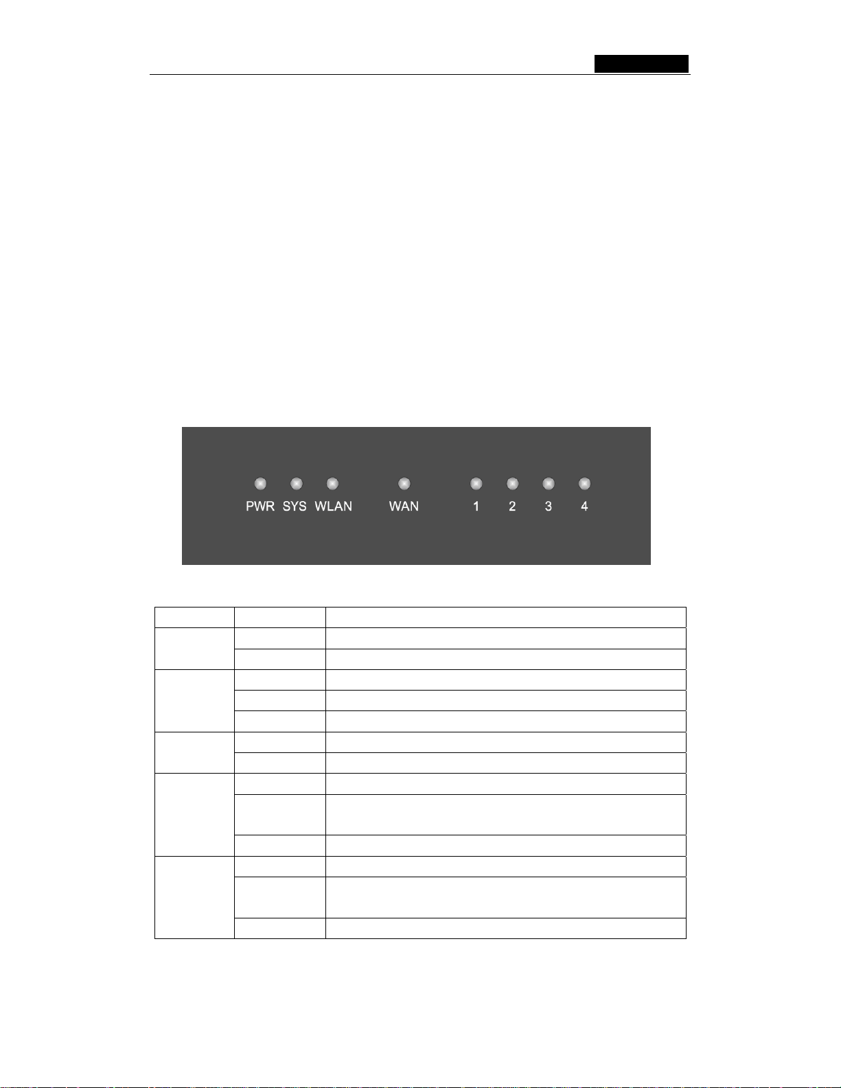
2.3.1 The Front Panel
The front panel of the SMCWBR14-G3 consists of several LED indicators, which is
designed to indicate connections. Viewed from the left table 2-1 describes the LED’s on
the front panel of the router.
Figure 2-1: Front Panel LED’s
Name Action Description
PWR
Not lit No Power
Lit up Power on
Lit up The router is initializing
SYS
Flashing The router is working properly
Not lit The router has a hardware error
WLAN
Not lit There is no wireless device linked to the device
Flashing The Wireless function is enabled
Not lit There is no device linked to the corresponding port
WAN
Lit up
There is a device linked to the corresponding port but no
activity
Flashing There is an active device linked to the corresponding port
Not lit There is no device linked to the corresponding port
LAN 1-4
Lit up
There is a device linked to the corresponding port but no
activity
Flashing There is an active device linked to the corresponding port
Table 2-1: The LED’s description
- 4 -
Page 20
SMCWBR14-G3 User Guide
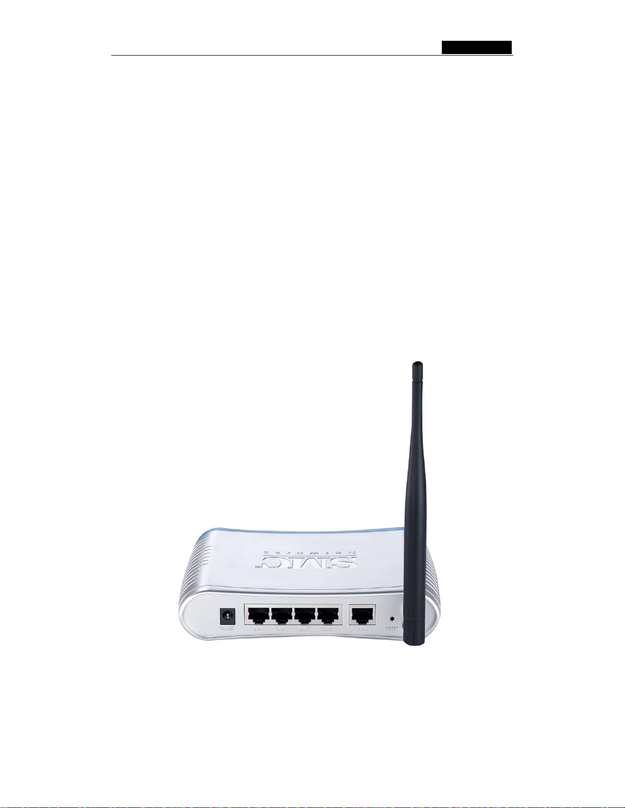
2.3.2 The Rear Panel
The rear panel contains the following:
¾ Power Input: Only use the power adapter supplied with the SMCWBR14-G3
54Mbps Wireless Router. Using a different adapter may result in the product being
damaged.
¾ Four 10/100Mbps RJ45 LAN ports for connecting the router to the local PCs
¾ One RJ45 WAN port for connecting the router to a Cable modem, DSL modem, or
Ethernet
¾ Reset button. There are two ways to reset the router's factory defaults:
1) Use the Factory Defaults function on System Tools -> Factory Defaults
page in the router's Web-based Utility.
2) Use the Factory Default Reset button: First, turn off the router's power.
Second, press and hold the default reset button then turn on the router's
power, until the SYS LED lights up (about 3 seconds). Last, release the
reset button and wait for the router to reboot.
Note: Ensure the router is powered on before it restarts completely.
¾ Wireless antenna
Figure 2-2: Rear Panel Image
- 5 -
Page 21

SMCWBR14-G3 User Guide
Chapter 3: Connecting the Router
3.1 System Requirements
¾ Broadband (Cable/xDSL) Internet service and Modem with Ethernet connection.
¾ 2.4GHz 802.11b/g wireless adapter installed on each PC. Alternatively an Ethernet
adapter can be used.
¾ Internet Explorer 5.5 or above, Netscape 4.7 or above, Mozilla Firefox 1.0 or above
3.2 Installation Environment Requ irements
¾ Do not place in direct sunlight or near a heater or heating vent
¾ Do not clutter or crowd. There should be at least 2 inches (5 cm) of clear space on
all sides of the router
¾ Well ventilated (especially if it is in a closet)
¾ Operating temperature: 0~40 (32~104)
¾ Operating Humidity: 10%~90%RH, Non-condensing
3.3 Connecting the Router
Before you install the router, you should connect your PC to the Internet through your
broadband service successfully. If there is any problem, please contact your ISP. After
that, please install the router according to the following steps. Don't forget to pull out the
power plug and keep your hands dry.
1. Power off your PC, Cable/DSL modem, and the router.
2. Locate an optimum location for the router. The best place is usually near the center
of the area in which your PC will wirelessly connect. The place must comply with the
Installation Environment Requirements
.
3. Adjust the direction of the antenna. Normally, upright is a good direction.
4. Connect the PCs and each Switch/Hub in your LAN to the LAN Ports on the router,
shown in figure 3-1. (If you have the wireless NIC and want to use wireless
connector, you can skip this step.)
5. Connect the DSL/Cable Modem to the WAN port on the router, shown in figure 3-1.
6. Connect the power adapter to the power input on the router, and the other end into
an electrical outlet. The router will start to work automatically.
7. Power on your PC and Cable/DSL modem.
- 6 -
Page 22
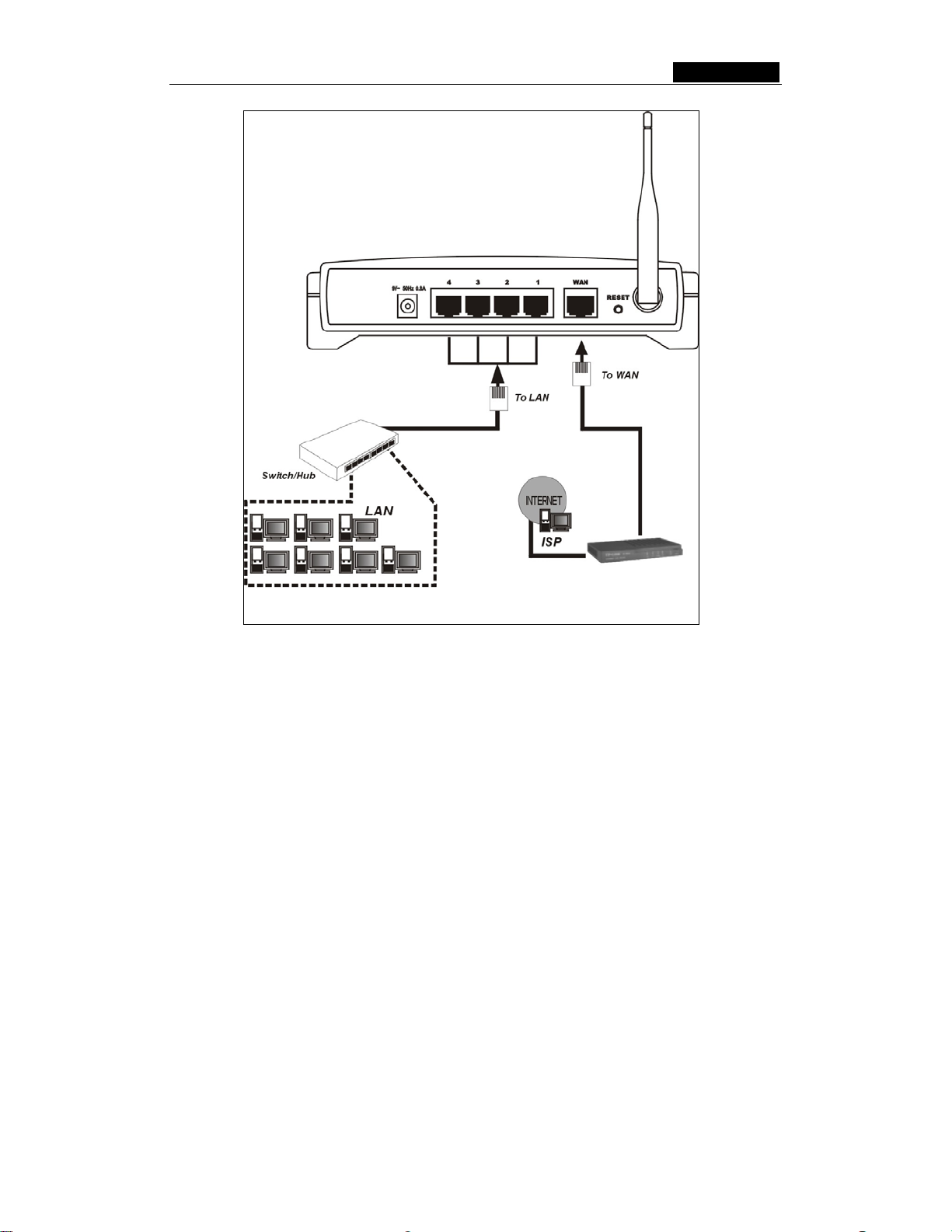
SMCWBR14-G3 User Guide
Figure 3-1: Hardware Installation of the SMCWBR14-G3 54Mbps Wireless Router
- 7 -
Page 23

SMCWBR14-G3 User Guide
Chapter 4: Quick Installation Guide
After connecting the SMCWBR14-G3 Router into your network, you should configure it.
This chapter describes how to configure the basic functions of your SMCWBR14-G3
Wireless Router. These procedures only take you a few minutes. You can access the
Internet via the router immediately after successfully configuring.
4.1 TCP/IP configuration
The default IP address of the SMCWBR14-G3 54Mbps Wireless Router is 192.168.2.1.
And the default Subnet Mask is 255.255.255.0. These values can be seen from the LAN.
They can be changed as you desire, as an example we use the default values for
description in this guide.
Connect the local PC to the LAN ports of the router. There are then two ways to
configure the IP address for your PC.
¾ Configure the IP address manually
1) Set up the TCP/IP Protocol for your PC. If you need instructions as to how to do
this, please refer to Appendix B: "Configuring the PC."
2) Configure the network parameters. The IP address is 192.168.2.xxx ("xxx" is
from 2 to 254), Subnet Mask is 255.255.255.0, and Gateway is 192.168.2.1
(The router's default IP address)
¾ Obtain an IP address automatically
1) Set up the TCP/IP Protocol in "Obtain an IP address automatically" mode on
your PC. If you need instructions as to how to do this, please refer to Appendix
B: "Configuring the PC."
2) Power off the router and PC. Then turn on the router and restart the PC. The
built-in DHCP server will assign IP address for the PC.
Now, you can run the Ping command in the command prompt to verify the network
connection between your PC and the router. The following example is in Windows 2000
OS.
Open a command prompt, and type ping 192.168.2.1, then press Enter.
If the result displayed is similar to that shown in figure 4-1, the connection between your
PC and the router has been established.
- 8 -
Page 24
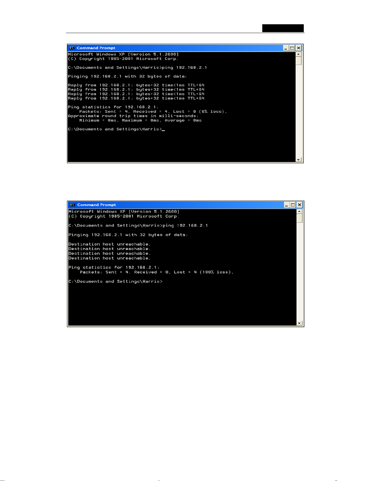
SMCWBR14-G3 User Guide
Figur e 4-1: Successful result of Ping command
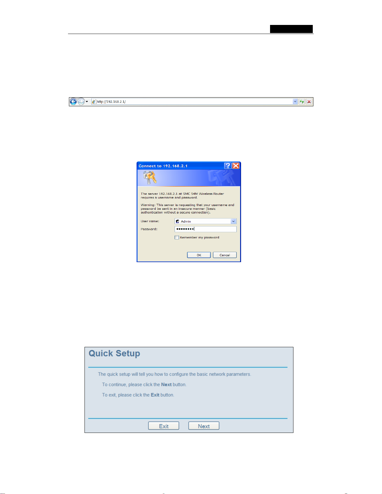
If the result displayed is similar to that shown in figure 4-2, it means that your PC has not
connected to the router.
Figur e 4-2: Failed result of Ping command
Please check it following these steps:
1. Is the connection between your PC and the router correct?
Note: The 1/2/3/4 LED’s of LAN port which you link to on the router and LED’s on
your PC's adapter should be lit.
2. Is the TCP/IP configuration for your PC correct?
Note: If the router's IP address is 192.168.2.1, your PC's IP address must be within
the range of 192.168.2.2 ~ 192.168.2.254, the gateway must be 192.168.2.1
- 9 -
Page 25
SMCWBR14-G3 User Guide
4.2 Quick Installation Guide
With a Web-browser, it is easy to configure and manage the SMCWBR14-G3 54Mbps
Wireless Router. The Web-based management interface can be used on any Windows,
Macintosh or UNIX OS with a web browser.
Connect to the router by typing http://192.168.2.1 in the address field of web browser.
Figure 4-3: Address field
After a moment, a login window will appear similar to that shown in Figure 4-4. Enter
Admin for the User Name and smcadmin for the Password, then click the OK button or
press the Enter key. Note: The username and password is case sensitive. Please make
sure to use the correct case for both username and password otherwise login will fail.
Figure 4-4: Login window
Note: If the above screen does not pop-up, it means that your web-browser has been set
to a proxy. Go to Tools menu>Internet Options>Connections>LAN Settings, in the screen
that appears, cancel the Using Proxy checkbox, and click OK to finish it.
If the User Name and Password are correct, you can configure the router using the web
browser. Please click the Quick Setup link on the left of the main menu and the Quick
Setup screen will appear.
Figure 4-5: Quick Setup
- 10 -
Page 26
SMCWBR14-G3 User Guide
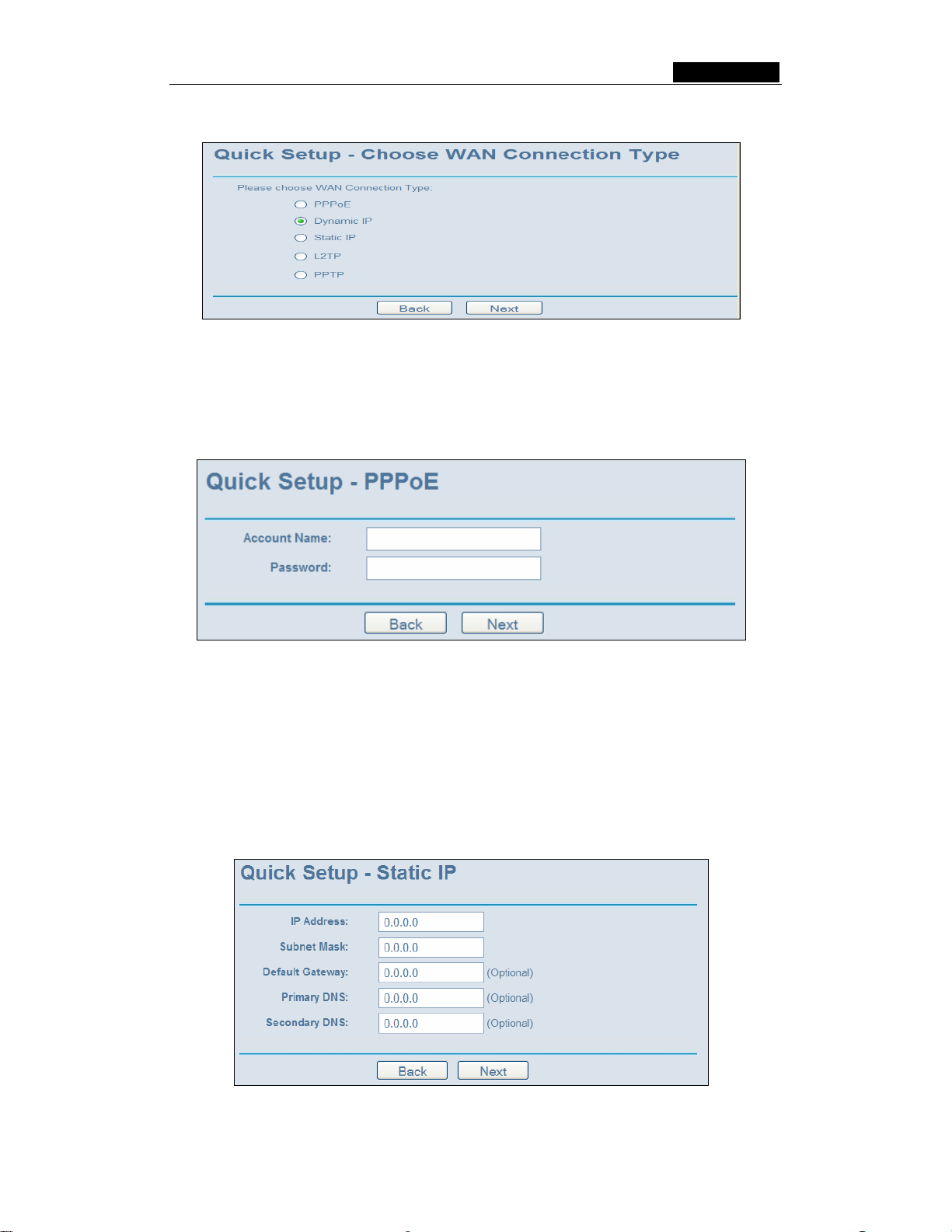
Click Next, then Choose WAN Connection Type page will appear, shown in figure 4-6.
Figure 4-6: Choose WAN Connection Type
The router supports five popular ways to connect to the Internet. Please select
connection type supported by your ISP. If you are unsure what setting to use, contact
your ISP. Click Next to continue.
If you choose "PPPoE", you will see this page shown in figure 4-7:
Figure 4-7: Quick Setup - PPPoE
¾ User Name and Password - Enter the User Name and Password provided by your
ISP. These fields are case sensitive. If you have difficulty with this process, please
contact your ISP.
If you choose "Dynamic IP", the router will automatically receive the IP parameters from
your ISP without needing to enter any parameters.
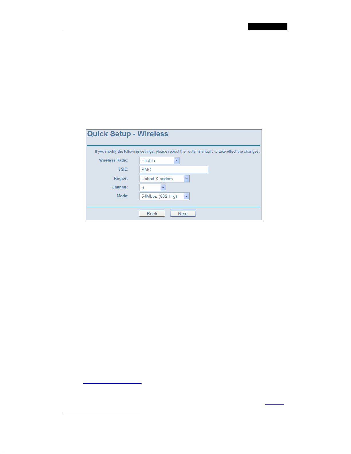
If you Choose "Static IP", the Static IP settings page will appear, shown in figure 4-8:
Figure 4-8: Quick Setup - Static IP
- 11 -
Page 27
SMCWBR14-G3 User Guide
Note - The IP parameters should have been provided by your ISP.
¾ IP Address - This is the WAN IP address as seen by external users on the Internet
(including your ISP). Enter the IP address into the field.
¾ Subnet Mask - The Subnet Mask is used for the WAN IP address, it is usually
255.255.255.0
¾ Default Gateway - Enter the gateway IP address into the box if required.
¾ Primary DNS - Enter the DNS Server IP address into the boxes if required.
¾ Secondary DNS - If your ISP provides another DNS server, enter it into this field.
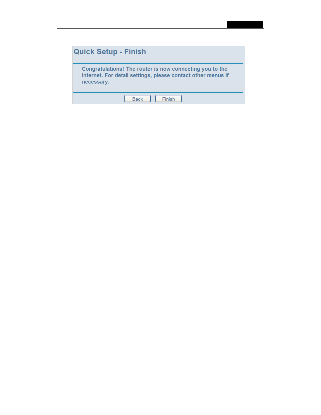
After you complete the above, click Next, the Wireless settings page will appear, shown
in figure 4-9.
Figure 4-9: Quick Setup - Wireless settings
In this page, you can configure the following wireless parameters:
¾ Wireless Radio - Indicates whether the Access Point feature of the router is
enabled or disabled. If disabled, the WLAN LED on the front panel will not be lit and
the wireless stations will not be able to access the router. If enabled, the WLAN
LED will be lit up and wireless stations will be able to access the router.
¾ SSID - Enter a value of up to 32 characters. The same SSID must be assigned to
all wireless devices on your network. The default SSID is SMC. This value is
case-sensitive. For example, SMC is NOT the same as smc.
¾ Region - Select your region from the pull-down list. This field specifies the region where
the wireless function of the router can be used. It may be illegal to use the wireless
function of the router in a region other than one of those specified in this field.
¾ Channel - The current channel in use. This field determines which operating
frequency will be used.
¾ Mode - Indicates the current mode 54Mbps (802.11g), 11Mb ps ( 80 2 .11 b ). If you
select 54Mbps (802.11g), it is backwards compatible with 11Mbps (802.11b).
These settings are only for basic wireless parameters, for advanced settings, please
refer to Section 5.5: "Wireless."
Note: The change of wireless settings won't take effect until the router reboots! You can
reboot it manually. If you need instructions as to how to do this, please refer to Section
5.11.5: "Rebooting the Router"
- 12 -
Page 28
SMCWBR14-G3 User Guide
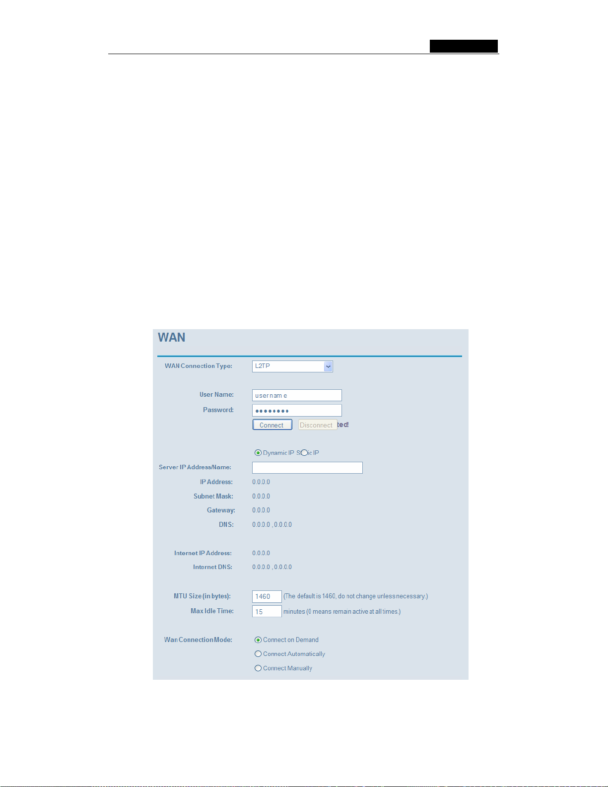
Click the Next button, you will then see the Finish page:
Figure 4-10: Quick Setup - Finish
After finishing all configurations of basic network parameters, please click Finish button
to exit this Quick Setup.
- 13 -
Page 29

SMCWBR14-G3 User Guide
Chapter 5: Configuring the Router
This chapter describes each web page's key functions.
5.1 login
After your successful login, you can configure and manage the router. There are ten main
menus on the left of the web-based utility. Submenus will be available after you click one
of the main menus. The eleven main menus are: Status, Quick Setup, Network,
Wireless, DHCP, Forwarding, Security, Static Routing, IP & MAC Binding, DDNS and
System Tools. On the right of the web-based utility, there are the detailed explanations
and instructions for the corresponding page. To apply any settings you have altered on the
page, please click the Save button.
The detailed explanation for each web pages key function is listed below.
5.2 Status
The Status page displays the router's current status and configuration. All information is
read-only.
1. LAN
This field displays the current settings or information for the LAN, including the MAC
address, IP address and Subnet Mask.
2. Wireless
This field displays basic information or status for wireless function, including Wireless
Radio, SSID, Channel, Mode, Wireless MAC address and IP address.
3. WAN
These parameters apply to the WAN port of the router, including MAC address, IP
address, Subnet Mask, Default Gateway, DNS server and WAN connection type.
If PPPoE is chosen as the WAN connection type, the Disconnect button will be
shown here while you are accessing the Internet. You can also cut the connection by
clicking the button. If you have not connected to the Internet, just click Connect to
establish the connection.
4. Traffic Statistics
This field displays the router's traffic statistics.
5. System Up Time
The amount of time from when the router was switched on or reset.
- 14 -
Page 30

SMCWBR14-G3 User Guide
Figure 5-1: Router Status
- 15 -
Page 31

SMCWBR14-G3 User Guide
5.3 Quick Setup
Please refer to Section 4.2: "Quick Installation Guide."
5.4 Network
Figure 5-2: Network submenu
There are three submenus under the Network menu (shown in figure 5-2): LAN, WAN
and MAC Clone. Click any of them, and you will be able to configure the corresponding
function. The detailed explanations for each submenu are provided below.
5.4.1 LAN
You can configure the IP parameters of LAN on this page.
Figure 5-3: LAN
¾ MAC Address - The physical address of the router, as seen from the LAN. The
value can't be changed.
¾ IP Address - Enter the IP address of your router in dotted-decimal notation (factory
default: 192.168.2.1).
¾ Subnet Mask - An address code that determines the size of the network. Normally
use 255.255.255.0 as the subnet mask.
Note:
a. If you change the IP Address of LAN, you must use the new IP Address to login the
router.
b. If the new LAN IP Address you set is not in the same subnet, the IP Address pool of
the DHCP server will not take effect, until they are re-configured.
c. If the new LAN IP Address you set is not in the same subnet, the Virtual Server and
DMZ Host will change accordingly at the same time.
5.4.2 WAN
You can configure the WAN port parameters on this page.
First, please choose the WAN Connection Type (Dynamic IP/Static IP/PPPoE/802.1X +
Dynamic IP/802.1X + Static IP/BigPond Cable/L2TP/PPTP) for Internet. The default
- 16 -
Page 32

SMCWBR14-G3 User Guide
type is Dynamic IP. If you aren’t given any login parameters (fixed IP Address, logging
ID, etc), please select Dynamic IP. If you are given a fixed IP (static IP), please select
Static IP. If you are given a user name and a password, please select the type your ISP
provided (PPPoE/BigPond/L2TP/PPTP)
use currently, please contact your ISP to obtain the correct information.
1. If you choose Dynamic IP, the router will automatically get IP parameters from
your ISP. You can see the page as follows (figure 5-4):
. If you are not sure which connection type you
Figure 5-4: WAN – Dynamic IP
This page displays the WAN IP parameters assigned dynamically by your ISP,
including IP address, Subnet Mask, Default Gateway, etc. Click the Renew button to
renew the IP parameters from your ISP. Click the Release button to release the IP
parameters.
MTU Size - The normal MTU (Maximum Transmission Unit) value for most Ethernet
networks is 1500 Bytes. For some ISPs you need to reduce the MTU. But this is
rarely required, and should not be done unless you are sure it is necessary for your
ISP connection.
If your ISP gives you one or two DNS addresses, select Use These DNS Servers
and enter the primary and secondary addresses into the correct fields. Otherwise,
the DNS servers will be assigned dynamically from your ISP.
Note: If you get address and find error when you go to a Web site, it is likely that
your DNS servers are set up improperly. You should contact your ISP to get DNS
server addresses.
- 17 -
Page 33

SMCWBR14-G3 User Guide
Get IP with Unicast DHCP - A few ISPs' DHCP servers do not support the
broadcast applications. If you cannot get the IP Address normally, you can choose
this option. (This is rarely required.)
2. If you choose Static IP, you should have fixed IP Parameters specified by your ISP.
The Static IP settings page will appear, shown in figure 5-5:
Figure 5-5: WAN - Static IP
You should type the following parameters into the spaces provided:
¾ IP Address - Enter the IP address in dotted-decimal notation provided by your ISP.
¾ Subnet Mask - Enter the subnet Mask in dotted-decimal notation provided by your
ISP, usually is 255.255.255.0.
¾ Default Gateway - (Optional) Enter the gateway IP address in dotted-decimal
notation provided by your ISP.
¾ MTU Size - The normal MTU (Maximum Transmission Unit) value for most
Ethernet networks is 1500 Bytes. For some ISPs you may need to modify the MTU.
But this is rarely required, and should not be done unless you are sure it is
necessary for your ISP connection.
¾ Primary DNS - (Optional) Enter the DNS address in dotted-decimal notation
provided by your ISP.
¾ Secondary DNS - (Optional) Type another DNS address in dotted-decimal notation
provided by your ISP if provided.
- 18 -
Page 34

SMCWBR14-G3 User Guide
3. If you choose PPPoE, you should enter the following parameters (figure 5-6):
Figure 5-6: WAN - PPPoE
¾ User Name/Password - Enter the User Name and Password provided by your ISP.
These fields are case-sensitive.
¾ Connect on Demand - You can configure the router to disconnect your Internet
connection after a specified period of inactivity (Max Idle Time). If your Internet
connection has been terminated due to inactivity, Connect on D emand enables the
router to automatically re-establish your connection as soon as you attempt to
access the Internet again. If you wish to activate Connect on Demand, click the
radio button. If you want your Internet connection to remain active at all times, enter
0 in the Max Idle Time field. Otherwise, enter the number of minutes you want to
have elapsed before your Internet connection terminates.
Caution: Sometimes the connection is not disconnected although you specify a Max
Idle Time, since some applications are visiting the Internet continually in the
background.
¾ Connect Automatically - Connect automatically after the router is disconnected. To
use this option, click the radio button.
¾ Time-based Connecting - You can configure the router to make it connect or
disconnect based on time. Enter the start time in HH:MM format for connecting and
end time in HH:MM format for disconnecting in the Period of Time fields.
Note: Only when you have configured the system time on System Tools -> Time
page, will the Time-based Connecting function take effect.
¾ Connect Manually - You can configure the router to make it connect or disconnect
manually. After a specified period of inactivity (Max Idle Time), the router will
disconnect from the Internet connection, and you will not be able to re-establish your
- 19 -
Page 35

SMCWBR14-G3 User Guide
connection automatically as soon as you attempt to access the Internet again. To
use this option, click the radio button. If you want your Internet connection to remain
active at all times, enter "0" in the Max Idle Time field. Otherwise, enter the number
time in minutes that you wish to have the Internet connecting last unless a new link
is requested.
Caution: Sometimes the connection is not disconnected although you specify a Max
Idle Time, since some applications are visiting the Internet continually in the
background.
Click the Connect button to connect immediately, Click the Disconnect button to
disconnect immediately.
Click the Advanced Settings button to set up the advanced option, the page shown
in figure 5-7 will then appear:
Figure 5-7: PPPoE Advanced Settings
¾ Packet MTU - The default MTU size is 1492 bytes, which value is usually fine. For
some ISPs, you need modify the MTU. This should not be done unless you are sure
it is necessary for your ISP.
¾ Service Name/AC Name - The service name and AC (Access Concentrator) name,
these should not be configured unless you are sure it is necessary for your ISP.
¾ ISP Specified IP Address - If you know that your ISP does not automatically
transmit your IP address to the router during login, click “Use the IP Address
specified by ISP” check box and enter the IP Address in dotted-decimal notation,
which your ISP provided.
- 20 -
Page 36

SMCWBR14-G3 User Guide
¾ Detect Online Interval - The default value is 0, you can input the value between 0
and 120. The router will detect Access Concentrator online at every interval between
seconds. If the value is 0, it means, do not detect.
¾ DNS IP address - If you know that your ISP does not automatically transmit DNS
addresses to the router during login, click “Use the following DNS servers”
checkbox and enter the IP address in dotted-decimal notation of your ISP’s primary
DNS server. If a secondary DNS server address is available, enter it as well.
Click the Save button to save your settings.
4. If you choose 802.1X + Dynamic IP, you should enter the follow parameters(figure
5-8) :
Figure 5-8: 802.1X + Dynamic IP Settings
¾ User Name - Enter the user name for 802.1X authentication provided by your ISP
¾ Password - Enter the password for 802.1X authentication provided by your ISP.
Click Login to start 802.1X authentication.
Click Logout to end 802.1X authentication.
¾ Host Name - This field is required to be filled by some service provider.
- 21 -
Page 37

SMCWBR14-G3 User Guide
5. If you choose 802.1X + Static IP, you should enter the follow parameters(figure
5-9) :
Figure 5-9: 802.1X + Static IP Settings
¾ User Name - Enter the user name for 802.1X authentication provided by your ISP
¾ Password - Enter the password for 802.1X authentication provided by your ISP.
Click Login to start 802.1X authentication.
Click Logout to end 802.1X authentication.
¾ IP Address - Enter the IP address in dotted-decimal notation provided by your ISP.
¾ Subnet Mask - Enter the subnet Mask in dotted-decimal notation provided by your
ISP.
¾ Default Gateway - (Optional) Enter the default gateway IP address in
dotted-decimal notation provided by your ISP.
- 22 -
Page 38

SMCWBR14-G3 User Guide
6. If you choose BigPond Cable, you should enter the following parameters (figure
5-10):
Figure 5-10: BigPond Settings
¾ User Name/Password - Enter the User Name and Password provided by your ISP.
These fields are case-sensitive.
¾ Auth Server - Enter the authenticating server IP address or host name.
¾ Auth Domain - Type in the domain suffix server name based on your location. Eg,
NSW / ACT - nsw.bigpond.net.au
VIC / TAS / WA / SA / NT - vic.bigpond.net.au
QLD - qld.bigpond.net.au
¾ Connect on Demand - You can configure the router to disconnect from your Internet
connection after a specified period of inactivity (Max Idle Time). If your Internet
connection has been terminated due to inactivity, Connect on D emand enables the
router to automatically re-establish your connection as soon as you attempt to
access the Internet again. If you wish to activate Connect on Demand, click the
radio button. If you want your Internet connection to remain active at all times, enter
0 in the Max Idle Time field. Otherwise, enter the number of minutes you want to
have elapsed before your Internet connection terminates.
Caution: Sometimes the connection cannot be disconnected although you specify a
time to Max Idle Time, since some applications are visiting the Internet continually in
the background.
- 23 -
Page 39
SMCWBR14-G3 User Guide
¾ Connect Automatically - Connect automatically after the router is disconnected. To
use this option, click the radio button.
¾ Connect Manually - You can configure the router to make it connect or disconnect
manually. After a specified period of inactivity (Max Idle Time), the router will
disconnect from your Internet connection, and you will not be able to re-establish
your connection automatically as soon as you attempt to access the Internet again.
To use this option, click the radio button. If you want your Internet connection to
remain active at all times, enter "0" in the Max Idle Time field. Otherwise, enter the
number in minutes that you wish to have the Internet connecting last unless a new
link is requested.
Caution: Sometimes the connection cannot be disconnected although you specify a
time to Max Idle Time, since some applications are visiting the Internet continually in
the background.
Click the Connect button to connect immediately, Click the Disconnect button to
disconnect immediately.
7. If you choose L2TP, you should enter the following parameters (figure 5-11):
Figure 5-11: L2TP Settings
- 24 -
Page 40

SMCWBR14-G3 User Guide
¾ User Name/Password - Enter the User Name and Password provided by your ISP.
These fields are case-sensitive.
¾ Dynamic IP/ Static IP – Choose either as you are given by your ISP.
Click the Connect button to connect immediately, Click the Disconnect button to
disconnect immediately.
¾ Connect on Demand - You can configure the router to disconnect from your Internet
connection after a specified period of inactivity (Max Idle Time). If your Internet
connection has been terminated due to inactivity, Connect on D emand enables the
router to automatically re-establish your connection as soon as you attempt to
access the Internet again. If you wish to activate Connect on Demand, click the
radio button. If you want your Internet connection to remain active at all times, enter
0 in the Max Idle Time field. Otherwise, enter the number of minutes you want to
have elapsed before your Internet connection terminates.
Caution: Sometimes the connection cannot be disconnected although you specify a
time to Max Idle Time, since some applications is visiting the Internet continually in
the background.
¾ Connect Automatically - Connect automatically after the router is disconnected. To
use this option, click the radio button.
¾ Connect Manually - You can configure the router to make it connect or disconnect
manually. After a specified period of inactivity (Max Idle Time), the router will
disconnect from your Internet connection, and you will not be able to re-establish
your connection automatically as soon as you attempt to access the Internet again.
To use this option, click the radio button. If you want your Internet connection to
remain active at all times, enter "0" in the Max Idle Time field. Otherwise, enter the
number in minutes that you wish to have the Internet connecting last unless a new
link is requested.
Caution: Sometimes the connection cannot be disconnected although you specify a
time to Max Idle Time, since some applications is visiting the Internet continually in
the background.
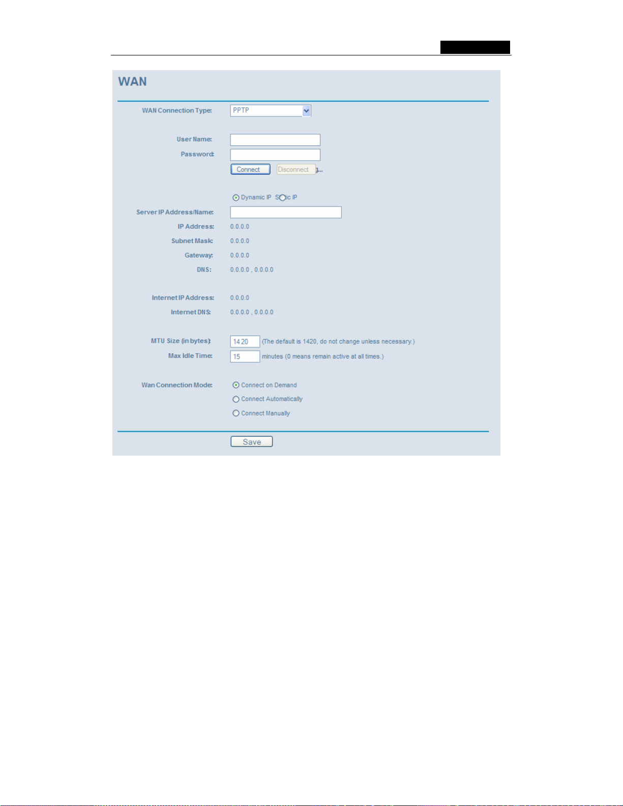
8. If you choose PPTP, you should enter the following parameters (figure 5-12):
- 25 -
Page 41
SMCWBR14-G3 User Guide
Figure 5-12: PPTP Settings
¾ User Name/Password - Enter the User Name and Password provided by your ISP.
These fields are case-sensitive.
¾ Dynamic IP / Static IP – Choose either as you are given by your ISP and enter the
ISP’s IP address or the domain name.
If you choose static IP and enter the domain name, you should also enter the DNS
assigned by your ISP. And click the Save button.
Click the Connect button to connect immediately, Click the Disconnect button to
disconnect immediately.
¾ Connect on Demand - You can configure the router to disconnect from your Internet
connection after a specified period of inactivity (Max Idle Time). If your Internet
connection has been terminated due to inactivity, Connect on D emand enables the
router to automatically re-establish your connection as soon as you attempt to
access the Internet again. If you wish to activate Connect on Demand, click the
radio button. If you want your Internet connection to remain active at all times, enter
0 in the Max Idle Time field. Otherwise, enter the number of minutes you want to
- 26 -
Page 42

SMCWBR14-G3 User Guide
have elapsed before your Internet connection terminates.
Caution: Sometimes the connection cannot be disconnected although you specify a
time to Max Idle Time, since some applications are visiting the Internet continually in
the background.
¾ Connect Automatically - Connect automatically after the router is disconnected. To
use this option, click the radio button.
¾ Connect Manually - You can configure the router to make it connect or disconnect
manually. After a specified period of inactivity (Max Idle Time), the router will
disconnect from your Internet connection, and you will not be able to re-establish
your connection automatically as soon as you attempt to access the Internet again.
To use this option, click the radio button. If you want your Internet connection to
remain active at all times, enter "0" in the Max Idle Time field. Otherwise, enter the
number in minutes that you wish to have the Internet connecting last unless a new
link is requested.
Caution: Sometimes the connection cannot be disconnected although you specify a
time to Max Idle Time, since some applications are visiting the Internet continually in
the background.
5.4.3 MAC Clone
You can configure the MAC address of the WAN port on this page, figure 5-13:
Figure 5-13: MAC Address Clone
Some ISPs require that you register the MAC Address of your adapter, which is
connected to your cable, DSL modem or Ethernet during installation. Changes are rarely
needed here.
¾ WAN MAC Address - This field displays the current MAC address of the WAN port,
which is used for the WAN port. If your ISP requires that you register the MAC
address, please enter the registered MAC address into this field. The format for the
MAC Address is XX-XX-XX-XX-XX-XX (X is any hexadecimal digit).
¾ Your PC's MAC Address - This field displays the MAC address of the PC that is
managing the router. If the MAC address is required, you can click the Clone MAC
Address button and this MAC address will fill in the WAN MAC Address field.
- 27 -
Page 43

SMCWBR14-G3 User Guide
Click Restore Factory MAC to restore the MAC address of WAN port to the factory
default value.
Click the Save button to save your settings.
Note:
1) Only the PC on your LAN can use the MAC Address Clone feature.
2) If you click the Save button, the router will prompt you to reboot.
5.5 Wireless
Figure 5-14: Wireless menu
There are three submenus under the Wireless menu (shown in figure 5-14): Wireless
Settings, MAC Filtering and Wireles s Statistics. Click any of them, and you will be
able to configure the corresponding function. The detailed explanations for each
submenu are provided below.
5.5.1 Wireless Settings
The basic settings for the wireless network are set on this page, figure 5-15:
- 28 -
Page 44
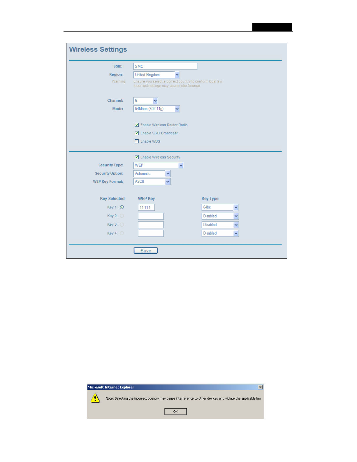
SMCWBR14-G3 User Guide
Figure 5-15: Wireless Settings
¾ SSID - Enter a value of up to 32 characters. The same name (SSID) must be
assigned to all wireless devices in your network. The default SSID is SMC, but it is
recommended strongly that you change your networks name (SSID) to a different
value. This value is case-sensitive. For example, SMC is NOT the same as smc.
¾ Region - Select your region from the pull-down list. This field specifies the region
where the wireless function of the router can be used. It may be illegal to use the
wireless function of the router in a region other than one of those specified in this
field. If your country or region is not listed, please contact your local government
agency for assistance.
When you select your local region from the pull-down list, click the Save button,
then the Note Dialog appears. Click OK.
- 29 -
Page 45

SMCWBR14-G3 User Guide
Note: Limited by local law regulations, version for North America does not have
region selection option.
¾ Channel - This field determines which operating frequency will be used. It is not
necessary to change the wireless channel unless you notice interference problems
with another nearby access point.
¾ Mode - Select the desired wireless mode. The options are:
• 54Mbps (802.11g) - Both 802.11g and 802.11b wireless stations can connect
to the router.
• 11Mbps (802.11b) - Only 802.11b wireless stations can connect to the router.
Note: The default is "54Mbps (802.11g)", which allows both 802.11g and 802.11b
wireless stations to connect to the router.
¾ Enable Wireless Router Radio - The wireless radio of this Router can be enabled
or disabled to allow wireless stations access. If enabled, wireless stations will be
able to access the router, otherwise, wireless stations will not be able to access.
¾ Enable SSID Broadcast - If you select the Enable SSID Broadcast checkbox, the
Wireless Router SSID will broadcast its name (SSID) on the air.
¾ Enable Wireless Security – The wireless security function can be enabled or
disabled. If disabled, the wireless stations will be able to connect the router without
encryption. It is recommended strongly that you choose this option to encrypt your
wireless network. The encryption settings described below.
¾ Authentication Type - You can select one of the following authentication types:
• WEP - Select WEP authentication type based on 802.11 authentications.
• WPA-PSK/WPA2-PSK - Select WPA/WPA2 authentication type based on
pre-shared passphrase.
• WPA /WPA2 - Select WPA/WPA2 authentication type based on Radius Server.
¾ Authentication Options - You can select one of the following authentication
options:
• When you select WEP for authentication type you can select the following
• Automatic - Select Shared Key or Open System authentication type
• Shared Key - Select 802.11 Shared Key authentication.
• Open System - Select 802.11 Open System authentication.
• When you select WPA-PSK/WPA2-PSK for authentication type you can select
• When you select WPA/WPA2 as an authentication type you can select
¾ WEP Key Format - You can select ASCII or Hexadecimal format. ASCII Code
Format stands for any combination of keyboard characters in the specified length.
Hexadecimal format stands for any combination of hexadecimal digits (0-9, a-f, A-F)
in the specified length.
authentication options:
automatically based on the wireless station request.
Automatic, WPA –PSK or WPA2-PSK as authentication options.
Automatic WPA or WPA2 as authentication option.
- 30 -
Page 46

SMCWBR14-G3 User Guide
¾ WEP Key settings - Select which of the four keys will be used and enter the
matching WEP key information for your network in the selected key radio button.
These values must be identical on all wireless stations in your network.
¾ Key Type - You can select the WEP key length (64-bit, or 128-bit, or 152-bit) for
encryption. "Disabled" means the WEP key entry is invalid.
• For 64-bit encryption - You can enter 10 hexadecimal digits (any combination
of 0-9, a-f, A-F, zero key is not permitted) or 5 ASCII characters.
• For 128-bit encryption - You can enter 26 hexadecimal digits (any combination
of 0-9, a-f, A-F, zero key is not permitted) or 13 ASCII characters.
• For 152-bit encryption - You can enter 32 hexadecimal digits (any combination
of 0-9, a-f, A-F, zero key is not permitted) or 16 ASCII characters.
¾ Encryption - When you select WPA-PSK/WPA2-PSK or WPA/WPA2 for
Authentication Type you can select either Automatic, TKIP or AES as
Encryptions.
Figure 5-15a: WPA-PSK/WPA2-PSK
¾ WPA-PSK/WPA2-PSK Passphrase - You can enter a WPA or WPA2 passphrase
between 8 and 63 characters long.
¾ Group Key Update Period - Specify the group key update interval in seconds. The
value can be either 0 seconds or from 30 seconds and up, 1-29 seconds are not
usable figures. Enter 0 to disable the update.
Figure 5-15b: WPA/WPA2
- 31 -
Page 47

SMCWBR14-G3 User Guide
¾ Radius Server IP - Enter the IP address of the Radius Server
¾ Radius Port - Enter the port number that the radius service used.
¾ Radius Password - Enter the password for the Radius Server.
Be sure to click the Save button to save your settings on this page.
Note: The router will reboot automatically after you click save.
5.5.2 MAC Filtering
The Wireless MAC Filtering for wireless networks are set on this page, figure 5-16:
Figure 5-16: Wireless MAC address Filtering
The Wireless MAC Address Filtering feature allows you to control wireless stations
accessing the router, which depend on the station's MAC addresses.
¾ MAC Address - The wireless station's MAC address that you want to access.
¾ Status - The status of this entry either Enabled or Disabled.
¾ Privilege - Select the privileges for this entry. You may select one of the following
Allow / Deny / 64-bit / 128-bit / 152-bit.
¾ Description - A simple description of the wireless station.
¾ WEP Key - Specify a unique WEP key (in Hexadecimal format) to access the router.
To set up an entry, follow these instructions:
First, you must decide whether the unspecified wireless stations can access the router or
not. If you desire that the unspecified wireless stations can access the router, please
select the radio button Allow the stations not specified by any enabled e ntries in the
list to access, otherwise, select the radio button Deny the stations not specified by
any enabled entries in the list to access.
To Add a Wireless MAC Address filtering entry, click the Add New… button. The "Add
or Modify Wireless MAC Address Filtering entry" page will appear, shown in figure
5-17:
- 32 -
Page 48
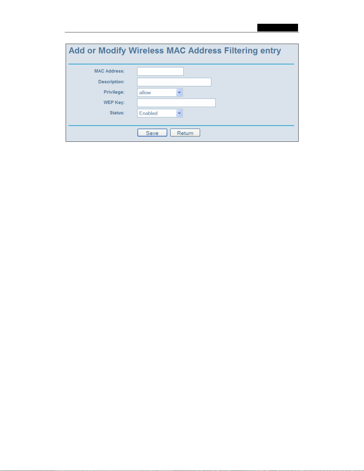
SMCWBR14-G3 User Guide
Figure 5-17: Add or Modify Wireless MAC Address Filtering entry
To add or modify a MAC Address Filtering entry, follow these instructions:
1. Enter the appropriate MAC Address into the MAC Address field. The format of the
MAC Address is XX-XX-XX-XX-XX-XX (X is any hexadecimal digit). For example:
00-0A-EB-B0-00-0B.
2. Enter a simple description of the wireless station in the Description field. For
example: Wireless station A.
3. Privilege - Select the privileges for this entry, one of Allow / Deny / 64-bit / 128-bit /
152-bit.
4. WEP Key - If you select 64-bit, 128-bit or 152-bit in the Privilege field, enter any
combination of hexadecimal digits (0-9, a-f, A-F) in the specified length. For
example: 2F34D20BE2.
5. Status - Select Enabled or Disabled for this entry on the Status pull-down list.
6. Click the Save button to save this entry.
To add additional entries, repeat steps 1-6.
Note: When 64-bit, or 128-bit, or 152-bit is selected, WEP Key will be enabled.
To modify or delete an existing entry:
1. Click the Modify in the entry you want to modify. If you want to delete the entry, click
the Delete.
2. Modify the information.
3. Click the Save button.
Click the Enable All button to make all entries enabled
Click the Disabled All button to make all entries disabled.
Click the Delete All button to delete all entries
Click the Next button to go to the next page and click the Previous button to return to the
previous page.
For example: If you desire that the wireless station A with MAC address 00-0A-EB-0007-BE be able to access the router. The wireless station B with MAC address 00-0A-EB-
- 33 -
Page 49

SMCWBR14-G3 User Guide
00-07-5F not be able to access the router, and the wireless station C with MAC address
00-0A-EB-00-07-8A be able to access the router when its WEP key is 2F34D20BE2E
54B326C5476586A, while all other wireless stations cannot access the router, you should
configure the Wireless MAC Address Filtering list by following these steps:
1. Click the Enable button to enable this function.
2. Select the radio button: Deny th e stations not spe cified by any enabled entries in
the list to access for Filtering Rules.
3. Delete all or disable all entries if there are any entries already.
4. Click the Add New... button and enter the MAC address 00-0A-EB-00-07-BE in the
MAC Address field, enter wireless station A in the Description field, select Allow in
the Privilege pull-down list and select Enabled in the Status pull-down list. Click the
Save and the Return button.
5. Click the Add New... button and enter the MAC address 00-0A-EB-00-07-5F in the
MAC Address field, enter wireless station B in the Description field, select Deny in
the Privilege pull-down list and select Enabled in the Status pull-down list. Click the
Save and the Return button.
6. Click the Add New... button and enter the MAC address 00-0A-EB-00-07-8A in the
MAC Address field, enter wireless station C in the Description field, select 128-bit
in the Privilege pull-down list, enter 2F34D20BE2E54B326C5476586A in the WEP
Key field and select Enabled in the Status pull-down list. Click the Save and the
Return button.
The filtering rules that configured should be similar to the following list:
Note:
a) If you select the radio button Al low the stations not spe cified by any enabled
entries in the list to access for Filtering Rules, the wireless station B will still
not be able to access the router, however, other wireless stations that are not in
the list will be able to access the router.
b) If you enable the function and select the Deny the stations not specified by
any enabled entries in the list to access for Filtering Rules, and there are
not any enable entries in the list, thus, no wireless stations can access the
router.
5.5.3 Wireless St ati sti cs
This page shows MAC Address, Cu r rent S tatus, Received P ack ets and Sent Packet s
for each connected wireless station.
- 34 -
Page 50

SMCWBR14-G3 User Guide
Figure 5-18: The router attached wireless stations
¾ MAC Address - The connected wireless station's MAC address
¾ Current Status - The connected wireless station's running status, one of
STA-AUTH / STA-ASSOC / AP-UP / WPA / WPA-PSK /WPA2/WPA2-PSK/None
¾ Received Packets - Packets received by the station
¾ Sent Packets - Packets sent by the station
You cannot change any of the values on this page. To update this page and to show the
current connected wireless stations, click on the Refresh button.
If the numbers of connected wireless stations go beyond one page, click the Next
button to go to the next page and click the Previous button to return the previous page.
Note: This page will be refreshed automatically every 5 seconds.
5.6 DHCP
Figure 5-19: The DHCP menu
There are three submenus under the DHCP menu (shown in figure 5-19): DHCP
Settings, DHCP Clients List and Address Reservation. Click any of them, and you will
be able to configure the corresponding function. The detailed explanations for each
submenu are provided below.
5.6.1 DHCP Settings
The router is set up by default as a DHCP (Dynamic Host Configuration Protocol) server,
which provides the TCP/IP configuration for all the PCs that are connected to the router
on the LAN. The DHCP Server can be configured on the page (shown in figure 5-20):
- 35 -
Page 51

SMCWBR14-G3 User Guide
Figure 5-20: DHCP Settings
¾ DHCP Server - Enable or Disable the DHCP server. If you disable the Server, you
must have another DHCP server within your network or else you must manually
configure the computer.
¾ Start IP Address - This field specifies the first of the addresses in the IP address
pool. 192.168.2.100 is the default start address.
¾ End IP Address - This field specifies the last of the addresses in the IP address
pool. 192.168.2.199 is the default end address.
¾ Address Lease Time - The Address Lea s e Tim e is the amount of time in which a
network user will be allowed connection to the router with their current dynamic IP
Address. Enter the amount of time, in minutes. The user will be "leased" this
dynamic IP Address. The range of the time is 1 ~ 2880 minutes. The default value
is 120 minutes.
¾ Default Gateway - (Optional.) Suggest to input the IP address of the LAN port of
the router, default value is 192.168.2.1
¾ Default Domain - (Optional.) Input the domain name of your network.
¾ Primary DNS - (Optional.) Input the DNS IP address provided by your ISP. Or
consult your ISP.
¾ Secondary DNS - (Optional.) Input the IP address of another DNS server if your
ISP provides two DNS servers.
Note: To use the DHCP server function of the router, you must configure all computers
on the LAN as "Obtain an IP Address automatically" mode. This function will take effect
until the router reboots.
5.6.2 DHCP Clients List
This page shows Client Name, MAC Address, Assigned IP and Lease Time for each
DHCP Client attached to the router (figure 5-21):
- 36 -
Page 52

SMCWBR14-G3 User Guide
Figure 5-21: DHCP Clients List
¾ Index - The index of the DHCP Client
¾ Client Name - The name of the DHCP client
¾ MAC Address - The MAC address of the DHCP client
¾ Assigned IP - The IP address that the router has allocated to the DHCP client.
¾ Lease Time - The time of the DHCP client leased. Before the time is up, DHCP
client will request to renew the lease automatically.
You cannot change any of the values on this page. To update this page and to show the
current attached devices, click on the Refresh button.
5.6.3 Address Reservation
When you specify a reserved IP address for a PC on the LAN, that PC will always
receive the same IP address each time when it accesses the DHCP server. Reserved
IP addresses should be assigned to servers that require permanent IP settings. This
page is used for address reservation (shown in figure 5-22).
Figure 5-22: Address Reservation
¾ MAC Address - The MAC address of the PC of which you want to reserve IP
address.
¾ Assigned IP Addr ess - The IP address of the router reserved.
¾ Status - The status of this entry either Enabled or Disabled.
To Reserve IP addresses:
1. Click the Add New button. (Pop-up figure 5-23)
2. Enter the MAC address (The format for the MAC Address is XX-XX-XX-XX-XX-XX.)
and IP address in dotted-decimal notation of the computer you wish to add.
- 37 -
Page 53

SMCWBR14-G3 User Guide
3. Click the Save button when finished.
Figure 5-23: Add or Modify a Address Reservation Entry
To modify or delete an existing entry:
1. Click the Modify in the entry you want to modify. If you want to delete the entry, click
the Delete.
2. Modify the information.
3. Click the Save button.
Click the Enable All button to make all entries enabled
Click the Disabled All button to make all entries disabled.
Click the Delete All button to delete all entries
Click the Next button to go to the next page and Click the Previous button to return the
previous page.
Note: The function won't take effect until the router reboots.
5.7 Forwarding
Figure 5-24: The Forwarding menu
There are four submenus under the Forwarding menu (shown in figure 5-24): Virtual
Servers, Port Triggering, DMZ and UPnP. Click any of them, and you will be able to
configure the corresponding function. The detailed explanations for each submenu are
provided below.
5.7.1 Virtual Servers
Virtual servers can be used for setting up public services on your LAN, such as DNS,
Email and FTP. A virtual server is defined as a service port, and all requests from the
Internet to this service port will be redirected to the computer specified by the server IP.
Any PC that was used for a virtual server must have a static or reserved IP Address
- 38 -
Page 54
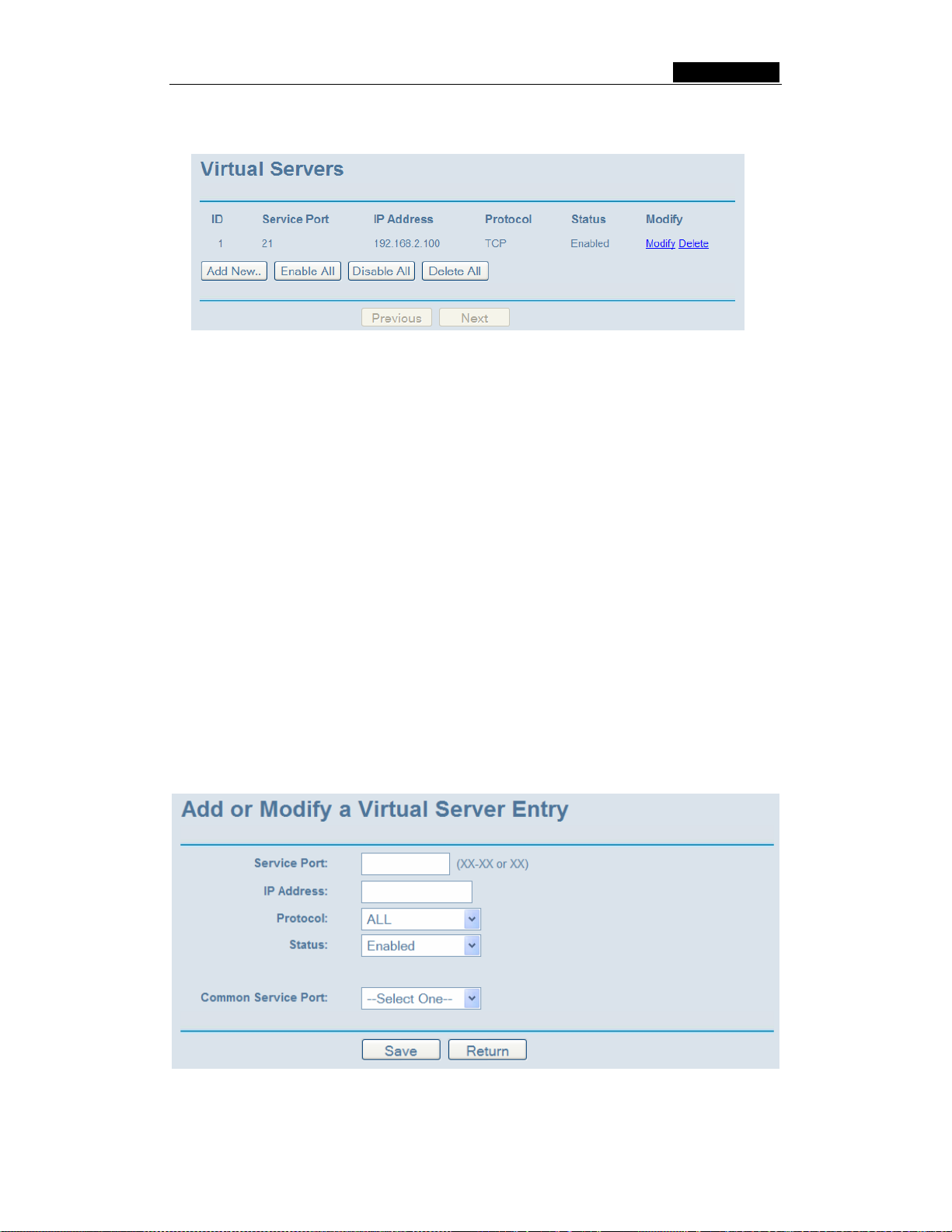
SMCWBR14-G3 User Guide
because its IP Address may change when using the DHCP function. You can set up
virtual servers on this page, shown in figure 5-25:
Figure 5-25:
¾ Service Port - The numbers of External Ports. You can type a service port or a
range of service ports (the format is XXX – YYY, XXX is Start port, YYY is End
port).
¾ IP Address - The IP Address of the PC providing the service application.
¾ Protocol - The protocol used for this application, either TCP, UDP, or All (all
protocols supported by the router).
¾ Status - The status of this entry either Enabled or Disabled.
Virtual Servers
To setup a virtual server entry:
1. Click the Add New button. (pop-up figure 5-26)
2. Select the service you want to use from the Common Service Port list. If the
Common Service Port list does not have the service that you want to use, type the
number of the service port or service port range in the Service Port box.
3. Type the IP Address of the computer in the Server IP Address box.
4. Select the protocol used for this application, either TCP or UDP, or All.
5. Select the Enable checkbox to enable the virtual server.
6. Click the Save button.
Figure 5-26: Add or Modify a Virtual Server Entry
- 39 -
Page 55
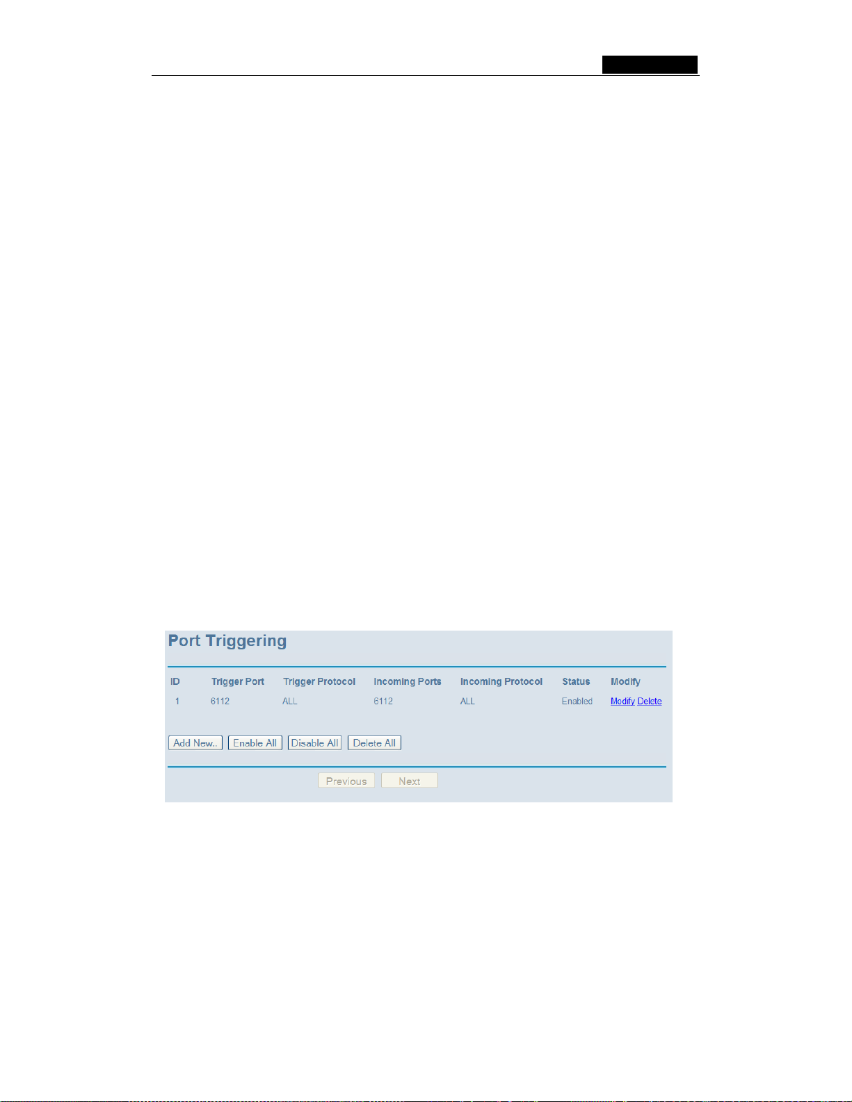
SMCWBR14-G3 User Guide
Note: It is possible that you have a computer or server that has more than one type of
available service. If so, select another service, and enter the same IP Address for that
computer or server.
To modify or delete an existing entry:
1. Click the Modify in the entry you want to modify. If you want to delete the entry, click
the Delete.
2. Modify the information.
3. Click the Save button.
Click the Enable All button to make all entries enabled
Click the Disabled All button to make all entries disabled.
Click the Delete All button to delete all entries
Click the Next button to go to the next page and Click the Previous button to return the
previous page.
Note: If you set the virtual server of service port as 80, you must set the web
management port on Security –> Remote Management page to be any value except
80 such as 8080. Or else there will be a conflict to disable the virtual server.
5.7.2 Port Triggering
Some applications require multiple connections, like Internet games, video
conferencing, Internet calling and so on. These applications cannot work with a pure
NAT router. Port Triggering is used for some of these applications that can work with an
NAT router. You can set up Port Triggering on this page shown in figure 5-27:
Figure 5-27:
Port Triggering
Once configured, operation is as follows:
1. A local host makes an outgoing connection using a destination port number
defined in the Trigger Port field.
2. The router records this connection, opens the incoming port or ports associated
with this entry in the Port Triggering table, and associates them with the local host.
3. When necessary the external host will be able to connect to the local host using
one of the ports defined in the Incoming Ports field.
- 40 -
Page 56

SMCWBR14-G3 User Guide
¾ Trigger Port - The port for outgoing traffic. An outgoing connection using this port
will "Trigger" this rule.
¾ Trigg er Protocol - The protocol used for Trigger Ports, either TCP, UDP, or All (all
protocols supported by the router).
¾ Incoming Ports Range - The port or port range used by the remote system when it
responds to the outgoing request. A response using one of these ports will be
forwarded to the PC that triggered this rule. You can input at most 5 groups of ports
(or port section). Every group of ports must be set apart with ",". For example,
2000-2038, 2050-2051, 2085, 3010-3030.
¾ Incoming Protocol - The protocol used for Incoming Ports Range, either TCP or
UDP, or ALL (all protocols supported by the router).
¾ Status - The status of this entry either Enabled or Disabled.
To add a new rule, enter the following data on the Port Triggering screen.
1. Click the Add New button. (pop-up figure 5-28)
2. Enter a port number used by the application when it generates an outgoing
request.
3. Select the protocol used for Trigger Port from the pull-down list, either TCP, UDP,
or All.
4. Enter the range of port numbers used by the remote system when it responds to
the PC's request.
5. Select the protocol used for Incoming Ports Range from the pull-down list, either
TCP or UDP, or All.
6. Select the Enable checkbox to enable.
7. Click the Save button to save the new rule.
Figure 5-28: Add or Modify a Triggering Entry
There are many popular applications in the Popular Application list. You can select it,
and the application will fill in the Trigger Port, incoming Ports Range boxes and
select the Enable checkbox. It has the same effect as adding a new rule.
To modify or delete an existing entry:
- 41 -
Page 57

SMCWBR14-G3 User Guide
1. Click the Modify in the entry you want to modify. If you want to delete the entry, click
the Delete.
2. Modify the information.
3. Click the Save button.
Click the Enable All button to make all entries enabled
Click the Disabled All button to make all entries disabled.
Click the Delete All button to delete all entries
Note:
1. When the trigger connection is released, the according opening ports will be closed.
2. Each rule allowed to be used only by one host on LAN synchronously. The trigger
connection of other hosts on LAN will be refused.
3. Incoming Port Range cannot overlap each other.
5.7.3 DMZ
The DMZ host feature allows one local host to be exposed to the Internet for a
special-purpose service such as Internet gaming or videoconferencing. DMZ host
forwards all the ports at the same time. Any PC whose port is being forwarded must have
its DHCP client function disabled and should have a new static IP Address assigned to it
because its IP Address may change when using the DHCP function. You can set up DMZ
host on this page shown in figure 5-29:
Figure 5-29: DMZ
To assign a computer or server to be a DMZ server:
1. Click the Enable radio button
2. Enter the local host IP Address in the DMZ Host IP Address field
3. Click the Save button.
Note: After you set the DMZ host, the firewall related to the host will not work.
5.7.4 UPnP
The Universal Plug and Play (UPnP) feature allows the devices, such as Internet
computers, to access the local host resources or devices as needed. UPnP devices can
be automatically discovered by the UPnP service application on the LAN. You can
configure UPnP on this page that shown in figure 5-30:
- 42 -
Page 58

SMCWBR14-G3 User Guide
Figure 5-30: UPnP Settings
¾ Current UPnP Status - UPnP can be enabled or disabled by clicking the Enable or
Disable button. As allowing this may present a risk to security, this feature is
disabled by default.
¾ Current UPnP Settings List - This table displays the current UPnP information.
• App Description – The description provided by the application in the UPnP
request
• External Port - External port, which the router opened for the application.
• Protocol - Which type of protocol is opened.
• Internal Port - Internal port, which the router opened for local host.
• IP Address - The UPnP device that is currently accessing the router.
• Status - Either Enabled or Disabled, “Enabled” means that port is still active,
otherwise, the port is inactive.
Click Refresh to update the Current UPnP Settings List.
5.8 Security
Figure 5-31: The Security menu
There are six submenus under the Security menu (shown in figure 5-31): Firewall, IP
Address Filtering, Domain Filtering, MAC Filtering, Remote Management and
Advanced Security. Click any of them, and you will be able to configure the
corresponding function. The detailed explanations for each submenu are provided
below.
5.8.1 Firewall
Using the Firewall page (shown in figure 5-32), you can turn the general firewall switch
- 43 -
Page 59

SMCWBR14-G3 User Guide
on or off. The default setting for the switch is ON. If the general firewall switch is off, even
if IP Address Filtering, DNS Filtering and MAC Filtering are enabled, their settings are
ineffective.
Figure 5-32: Firewall Settings
¾ Enable Firewall - the general firewall switch is on or off.
¾ Enable IP Address Filtering - set IP Address Filtering is enabled or disabled.
There are two default filtering rules of IP Address Filtering, either Allow or Deny
passing through the router.
¾ Enable Domain Filtering - set Domain Filtering is enabled or disabled.
¾ Enable MAC Filtering - set MAC Address Filtering is enabled or disabled. You can
select the default filtering rules of MAC Address Filtering, either Allow or Deny
accessing the router.
5.8.2 IP Address Filtering
The IP address Filtering feature allows you to control Internet Access by specific users
on your LAN based on their IP addresses. The IP address filtering are set on this page,
figure 5-33:
- 44 -
Page 60

SMCWBR14-G3 User Guide
Figure 5-33: IP address Filtering
To disable the IP Address Filtering feature, keep the default setting, Disabled. To set up
an IP Address Filtering entry, click Enable Firewall and Enable IP Address Filtering on
the Firewall page, and click the Add New… button. The page "Add or Modify an IP
Address Filtering entry" will appear shown in figure 5-34:
Figure 5-34: Add or Modify an IP Address Filtering Entry
To create or modify an IP Address Filtering entry, please follow these instructions:
1. Effective Time - Enter a range of time in HHMM format, which point to the range
time for the entry to take effect. For example, 0803 - 1705, the entry will take effect
from 08:03 to 17:05.
2. LAN IP Address - Enter a LAN IP Address or a range of LAN IP addresses in the
field, in dotted-decimal notation format. For example, 192.168.1.20 - 192.168.1.30.
Keep the field open, which means all LAN IP Addresses have been put into the field.
3. LAN Port - Enter a LAN Port or a range of LAN ports in the field. For example, 1030
- 2000. Keep the field open, which means all LAN ports have been put into the field.
4. WAN IP Address - Enter a WAN IP Address or a range of WAN IP Addresses in the
- 45 -
Page 61

SMCWBR14-G3 User Guide
field, in dotted-decimal notation format. For example, 61.145.238.6 – 61.145.238.47.
Keep the field open, which means all WAN IP Addresses have been put into the
field.
5. WAN Port - Enter a WAN Port or a range of WAN Ports in the field. For example, 25
– 110. Keep the field open, which means all WAN Ports have been put into the field.
6. Protocol - Select which protocol is to be used, either TCP, UDP, or All (all protocols
supported by the router).
7. Pass - Select either Allow or Deny through the router.
8. Status - Select Enabled or Disabled for this entry on the Status pull-down list.
9. Click the Save button to save this entry.
To modify or delete an existing entry:
1. Click the Modify in the entry you want to modify. If you want to delete the entry, click
the Delete.
2. Modify the information.
3. Click the Save button.
Click the Enable All button to make all entries enabled
Click the Disabled All button to make all entries disabled.
Click the Delete All button to delete all entries
You can change the entry’s order as desired. Fore entries are before hind entries. Enter
the ID number in the first box you want to move and another ID number in second box
you want to move to, and then click the Move button to change the entry’s order.
Click the Next button to the next page and click the Previous button to return to the
previous page.
For example: If you desire to block E-mail received and sent by the IP Address
192.168.1.7 on your local network, and to make the PC with IP Address 192.168.1.8
unable to visit the website of IP Address 202.96.134.12, while other PCs have no limit
you should specify the following IP address filtering list:
5.8.3 Domain Filtering
The Domain Filtering page (shown in figure 5-35) allows you to control access to certain
websites on the Internet by specifying their domains or key words.
- 46 -
Page 62

SMCWBR14-G3 User Guide
Figure 5-35: Domain Filtering
Before adding a Domain Filtering entry, you must ensure that Enable Firewall and
Enable Domain Filtering have been selected on the Firewall page. To Add a Domain
filtering entry, click the Add New… button. The page "Add or Modify a Domain
Filtering entry " will appear, shown in figure 5-36:
Figure 5-36 Add or Modify a Domain Filtering entry
To add or modify a Domain Filtering entry, follow these instructions:
1. Effective Time - Enter a range of time in HHMM format specifying the time for the
entry to take effect. For example, if you enter: 0803 - 1705, than the entry will take
effect from 08:03 to 17:05.
2. Domain Name - Type the domain or key word as desired in the field. A blank in the
domain field means all websites on the Internet. For example:
www.xxyy.com.cn
, .net.
3. Status - Select Enabled or Disabled for this entry on the Status pull-down list.
4. Click the Save button to save this entry.
To modify or delete an existing entry:
1. Click the Modify in the entry you want to modify. If you want to delete the entry, click
the Delete.
2. Modify the information.
3. Click the Save button.
- 47 -
Page 63

SMCWBR14-G3 User Guide
Click the Enabled All button to make all entries
Click the Disabled All button to make all entries disabled.
Click the Delete All button to delete all entries
Click the Next button to go to the next page and the Previous button to return to the
previous page.
For example, if you want to block the PCs on your LAN to access websites
www.xxyy.com.cn
, www.aabbcc.com and websites with .net in the end on the Internet
while no limit for other websites, you should specify the following Domain filtering list:
5.8.4 MAC Filtering
enabled.
Like the IP Address Filtering page, the MAC Address Filtering page (shown in figure 5-37)
allows you to control access to the Internet by users on your local network based on their
MAC Address.
Figure 5-37: MAC address Filtering
Before setting up MAC Filtering entries, you must ensure that Enable Firewall and
Enable MAC Filtering have been selected on the Firewall page. To Add a MAC Address
filtering entry, clicking the Add New… button. The page "Add or Modify a MAC
Address Filtering entry" will appear, shown in figure 5-38:
- 48 -
Page 64

SMCWBR14-G3 User Guide
Figure 5-38: Add or Modify a MAC Address Filtering entry
To add or modify a MAC Address Filtering entry, follow these instructions:
1. Enter the appropriate MAC Address into the MAC Address field. The format of the
MAC Address is XX-XX-XX-XX-XX-XX (X is any hexadecimal digit). For example:
00-0E-AE-B0-00-0B.
2. Type the description of the PC in the Description field. Fox example: John’s PC.
3. Status - Select Enabled or Disabled for this entry on the Status pull-down list.
4. Click the Save button to save this entry.
To add additional entries, repeat steps 1-4.
When finished, click the Return button to return to the MAC Address Filtering page.
To modify or delete an existing entry:
1. Click the Modify in the entry you want to modify. If you want to delete the entry, click
the Delete.
2. Modify the information.
3. Click the Save button.
Click the Enable All button to make all entries enabled.
Click the Disabled All button to make all entries disabled.
Click the Delete All button to delete all entries
Click the Next button to go to the next page and click the Previous button to return to the
previous page.
Fox example: If you want to block the PC with MAC addresses 00-0A-EB-00-07-BE and
00-0A-EB-00-07-5F to access the Internet, first, enable the Firewall and MAC Address
Filtering on the Firewall page, then, you should specify the Default MAC Address
Filtering Rule "Deny these PCs with effective rules to access the Internet" on the
Firewall page and the following MAC address filtering list on this page:
5.8.5 Remote Management
You can configure the Remote Management function on this page shown in figure 5-39.
- 49 -
Page 65

SMCWBR14-G3 User Guide
This feature allows you to manage your Router from a remote location, via the Internet.
Figure 5-39: Remote Management
¾ Web Management Port - Web browser access normally uses the standard HTTP
service port 80. This router’s default remote management web port number is 80.
For greater security, you can change the remote management web interface to a
custom port by entering that number in this box provided. Choose a number
between 1024 and 65534, but do not use the number of any common service port.
¾ Remote Management IP Address - This is the current address you will use when
accessing your router from the Internet. The default IP Address is 0.0.0.0. It means
this function is disabled. To enable this function, change the default IP Address to
another IP Address as desired.
To access the router, you will type your router's WAN IP Address into your browser's
Address (in IE) or Location (in Navigator) box, followed by a colon and the custom port
number. For example, if your Router's WAN address is 202.96.12.8 and you use port
number 8080, enter in your browser: http://202.96.12.8:8080
. You will be asked for the
router's password. After successfully entering the password, you will be able to access
the router's web-based utility.
Note: Be sure to change the router's default password to a very secure password.
5.8.6 Adv anc ed Secur it y
Using Advanced Security page (shown in figure 5-40), you can protect the router from
being attacked by TCP-SYN Flood, UDP Flood and ICMP-Flood from LAN.
- 50 -
Page 66
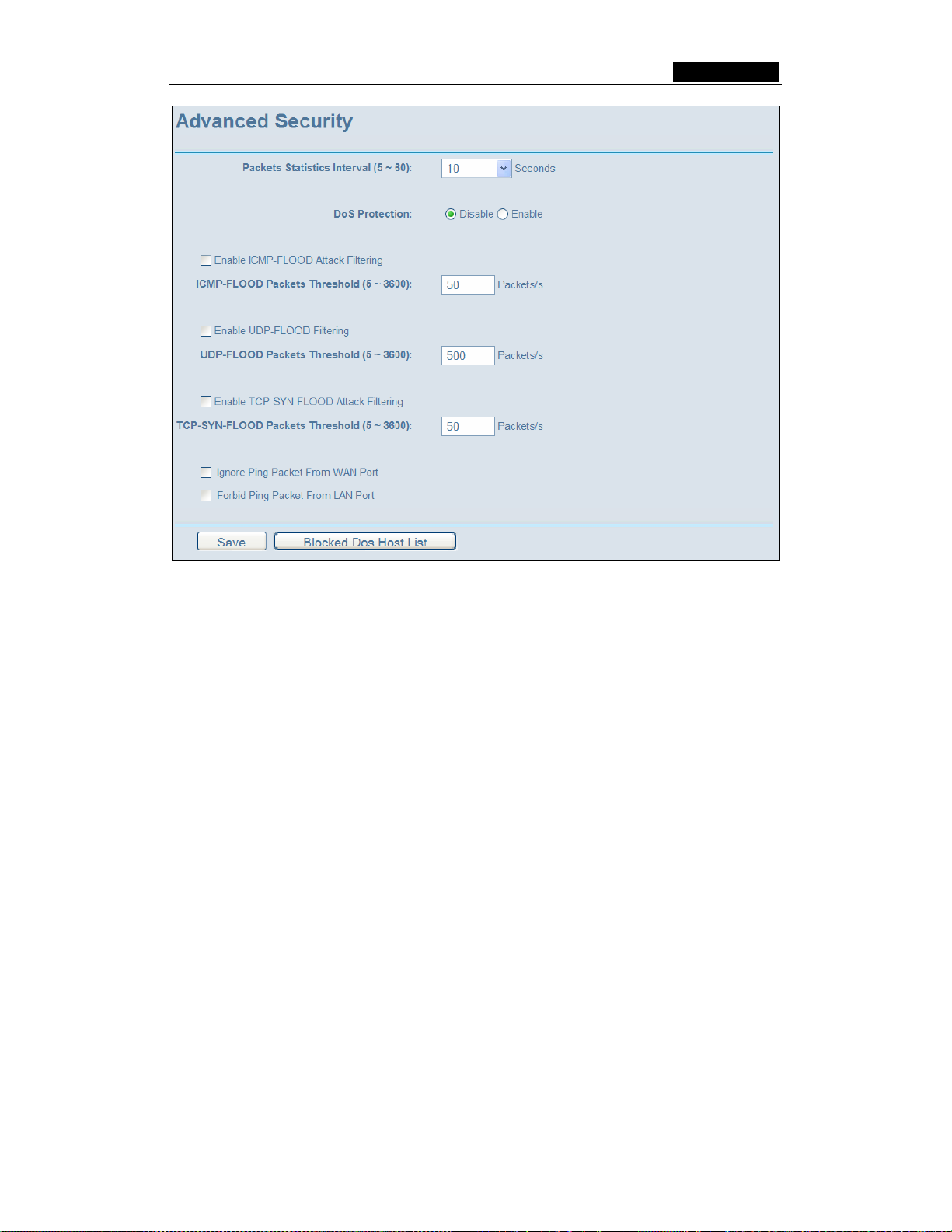
SMCWBR14-G3 User Guide
Figure 5-40: Advanced Security settings
¾ Packets Statistic interval (5 ~ 60) - The default value is 10. Select a value
between 5 and 60 seconds in the pull-down list. The Packets Statistic interval
value indicates the time section of the packets statistic. The result of the statistic
used for analysis by SYN Flood, UDP Flood and ICMP-Flood.
¾ DoS protection - Enable or Disable the DoS protection function. Only when it is
enabled, will the flood filters be effective.
¾ Enable ICMP-FLOOD Attack Filtering - Enable or Disable the ICMP-FLOOD
Attack Filtering.
¾ ICMP-FLOOD Packets threshold: (5 ~ 3600) - The default value is 50. Enter a
value between 5 ~ 3600 packets. When the current ICMP-FLOOD Packets
numbers is beyond the set value, the router will start up the blocking function
immediately.
¾ Enable UDP-FLOOD Filtering - Enable or Disable the UDP-FLOOD Filtering.
¾ UDP-FLOOD Packets threshold: (5 ~ 3600) - The default value is 50. Enter a
value between 5 ~ 3600 packets. When the current UPD-FLOOD Packets numbers
is beyond the set value, the router will start up the blocking function immediately.
¾ Enable TCP-SYN-FLOOD Attack Filtering - Enable or Disable the TCP-SYN-
FLOOD Attack Filtering.
¾ TCP-SYN-FLOOD Packets threshold: (5 ~ 3600) - The default value is 50. Enter
a value between 5 ~ 3600 packets. When the current TCP-SYN-FLOOD Packets
numbers is beyond the set value, the router will start up the blocking function
immediately.
- 51 -
Page 67

SMCWBR14-G3 User Guide
¾ Ignore Ping Packet from WAN Port - Enable or Disable ignore ping packet from
WAN port. The default is disabled. If enabled, the ping packet from the Internet
cannot access the router.
¾ Forbid Ping Packet from LAN Port - Enable or Disable forbidding Ping Packet to
access the router from the LAN port. The default value is disabled. If enabled, the
ping packet from the LAN port cannot access the router. (Defends against some
viruses)
Click the Save button to save the settings.
Click the Blocked DoS Host Table button to display the DoS host table by blocking. The
page will appear that shown in figure 5-41:
Figure 5-41: Thwarted DoS Host Table
This page shows Host IP Address and Host MAC Address for each host blocked by
the router.
¾ Host IP Address- The IP address that blocked by DoS are displayed here.
¾ Host MAC Address - The MAC address that blocked by DoS are displayed here.
To update this page and to show the current blocked host, click on the Refresh button.
Click the Clear All button to clear all displayed entries. After the table is empty the
blocked host will regain the capability to access Internet.
Click the Return button to return to the Advanced Security page
5.9 Static Routing
A static route is a pre-determined path that network information must travel to reach a
specific host or network. To add or delete a route, work in the area under the Static
Routing page (shown in figure 5-42).
Figure 5-42: Static Routing
To add static routing entries:
1. Click the Add New button. (pop-up figure 5-43)
- 52 -
Page 68

SMCWBR14-G3 User Guide
2. Enter the following data:
¾ Destination IP Address - The Destination IP Address is the address of the
network or host that you want to assign to a static route.
¾ Subnet Mask - The Subnet Mask determines which portion of an IP Address is the
network portion, and which portion is the host portion.
¾ Gateway - This is the IP Address of the gateway device that allows for contact
between the router and the network or host.
3. Select Enabled or Disabled for this entry on the Status pull-down list..
4. Click the Save button to save it.
Figure 5-43: Add or Modify a Static Route Entry
To modify or delete an existing entry:
1. Click the Modify in the entry you want to modify. If you want to delete the entry, click
the Delete.
2. Modify the information.
Click the Save button.
3.
Click the Enable All button to make all entries enabled.
Click the Disabled All button to make all entries disabled.
Click the Delete All button to delete all entries
5.10 DDNS
The router offers a Dynamic Domain Name System (DDNS) feature. DDNS lets you
assign a fixed host and domain name to a dynamic Internet IP Address. It is useful when
you are hosting your own website, FTP server, or other server behind the router. Before
using this feature, you need to sign up for DDNS service providers such as
www.dyndns.org
provider will give you a password or key.
To set up for DDNS, follow these instructions:
5.10.1Dyndns.org DDNS
, www.oray.net or www.comexe.cn. The Dynamic DNS client service
If your selected dynamic DNS Service Provider is www.dyndns.org
appear as shown in figure 5-44:
- 53 -
, the page will
Page 69

SMCWBR14-G3 User Guide
Figure 5-44 Dyndns.org DDNS Settings
To set up for DDNS, follow these instructions:
1. Type the domain names your dynamic DNS service provider gave.
2. Type the User Name for your DDNS account.
3. Type the Password for your DDNS account.
4. Click the Login button to login to the DDNS service.
¾ Connection Status -The status of the DDNS service connection is displayed here.
Click Logout to logout of the DDNS service.
5.10.2 Oray.net DDNS
If your selected dynamic DNS Service Provider is www.oray.net
as shown in figure 5-45:
Figure 5-45: Oray.net DDNS Settings
, the page will appear
To set up for DDNS, follow these instructions:
- 54 -
Page 70

SMCWBR14-G3 User Guide
1. Type the User Name for your DDNS account.
2. Type the Password for your DDNS account.
3. Click the Login button to login the DDNS service.
¾ Connection Status - The status of the DDNS service connection is displayed
here.
¾ Domain Name - The domain names are displayed here.
Click Logout to logout the DDNS service.
5.10.3 Comexe.cn DDNS
If your selected dynamic DNS Service Provider is www.comexe.cn
, the page will
appear as shown in figure 5-46:
Figure 5-46: Comexe.cn DDNS Settings
To set up for DDNS, follow these instructions:
1. Type the domain names your dynamic DNS service provider gave.
2. Type the User Name for your DDNS account.
3. Type the Password for your DDNS account.
4. Click the Login button to login to the DDNS service.
¾ Connection Status -The status of the DDNS service connection is displayed here.
Click Logout to logout of the DDNS service.
- 55 -
Page 71

SMCWBR14-G3 User Guide
5.11 System Tools
Figure 5-47: The System Tools menu
There are eight submenus under the System Tools menu (shown in figure 5-47): Time,
Firmware, Factory Defaults, Backup and Restore, Reboot, Password, Log and
Statistics. Click any of them, and you will be able to configure the corresponding
function. The detailed explanations for each submenu are provided below.
5.11.1 Time
You can set time manually or get GMT from the Internet for the router on this page
(shown in figure 5-48):
Figure 5-48: Time settings
¾ Time Zone - Select your local time zone from this pull down list.
¾ Date - Enter your local date in MM/DD/YY into the right blanks.
¾ Time - Enter your local time in HH/MM/SS into the right blanks.
Time setting follows these steps below:
1. Select your local time zone.
2. Enter date and time in the right blanks
- 56 -
Page 72

SMCWBR14-G3 User Guide
3. Click Save.
Click the Get GMT button to get GMT time from Internet if you have connected to
Internet.
If you’re using Daylight saving time, please follow the steps below.
1. Select using daylight saving time.
2. Enter daylight saving beginning time and end time in the right blanks.
3. Click Save.
Note:
1. This setting will be used for some time-based functions such as firewall. You
must specify your time zone once you login to the router successfully, if not, the
time limited on these functions will not take effect.
2. The time will be lost if the router is turned off.
3. The router will obtain GMT automatically from Internet if it has already connected
to Internet.
5.11.2 Firmware
The page (shown in figure 5-49) allows you to upgrade the latest version firmware to
keep your router up-to-date.
Figure 5-49: Firmware Upgrade
New firmware is posted at www.smc.com and can be downloaded for free. If the router is
not experiencing difficulties, there is no need to upgrade firmware, unless the new
firmware supports a new feature you need.
Note: When you upgrade the router's firmware, you will lose current configuration
settings, so make sure you backup the router’s settings before you upgrade its
firmware.
To upgrade the router's firmware, follow these instructions:
1. Download the latest firmware upgrade file from the SMC website (www.smc.com
).
2. Click Browse to view the folders and select the downloaded file.
3. Click the Upgrade button.
¾ Firmware Version - Displays the current firmware version.
¾ Hardware Version - Displays the current hardware version. The hardware version of
the upgrade file must accord with the current hardware version.
Note:
- 57 -
Page 73

SMCWBR14-G3 User Guide
1. Do not turn off the router or press the Reset button while the firmware is
being upgraded.
2. The router will reboot after the Upgrading has been finished.
5.11.3 Factory Defaults
This page (shown in figure 5-50) allows you to restore the factory default settings for the
router.
Figure 5-50: Restore Factory Default
Click the Restore button to reset all configuration settings to their default values.
• The default User Name: Admin
• The default Password: smcadmin
• The default IP Address: 192.168.2.1
• The default Subnet Mask: 255.255.255.0
Note: Any settings you have saved will be lost when the default settings are restored.
5.11.4 Backup and Restore
This page (shown in figure 5-51) allows you to save current configuration of router as
backup or restore the configuration file you saved before.
Figure 5-51: Backup & Restore Configuration
¾ Click the Backup button to save all configuration settings as a backup file in your
local computer.
¾ To restore the router's configuration, follow these instructions:
• click the Browse button to select the backup file which you want to restore.
• Click the Restore button.
Note: The current configuration will be covered with the uploading configuration file. The
restoration process lasts for 20 seconds and the router will restart automatically. Keep
the router on during the restoring process, to prevent any damage.
- 58 -
Page 74

SMCWBR14-G3 User Guide
5.11.5 Reboot
This page (shown in figure 5-52) allows you to reboot the router.
Figure 5-52: Reboot the router
Click the Reboot button to reboot the router.
Some settings of the router will take effect only after rebooting, which include:
• Change LAN IP Address. (System will reboot automatically)
• MAC Clone (system will reboot automatically)
• DHCP service function.
• Static address assignment of DHCP server.
• Web Service Port of the router.
• Upgrade the firmware of the router (system will reboot automatically).
• Restore the router's settings to factory default (system will reboot
automatically).
5.11.6 Password
This page (shown in figure 5-53) allows you to change the factory default user name and
password of the router.
Figure 5-53: Password
It is recommended strongly that you change the factory default user name and password
of the router. All users who try to access the router's web-based utility or Quick Setup will
be prompted for the router's user name and password.
Note: The new user name and password must not exceed 14 characters in length and
must not include any spaces. Enter the new Password twice to confirm it.
Click the Save button when finished.
Click the Clear All button to clear all.
- 59 -
Page 75

SMCWBR14-G3 User Guide
5.11.7 Log
This page (shown in figure 5-54) allows you to query the logs of the router.
Figure 5-54: System Log
The router can keep logs of all traffic. You can query the logs to find what happened to
the router.
Click the Refresh button to refresh the logs.
Click the Clear Log button to clear all the logs.
5.11.8 Statistics
The Statistics page (shown in figure 5-55) displays the network traffic of each PC in LAN,
including total traffic and traffic of the last Packets Statistic interval seconds.
Figure 5-55: Statistics
¾ Current Statistics Status - Enable or Disable. The default value is disabled. To
enable, click the Enable button. If disabled, the function of DoS protection in
Security settings will be ineffective.
¾ Packets Statistics Interval - The default value is 10. Select a value between 5 and
60 seconds in the pull-down list. The Packets Statistic interval indicates the time
section of the packets statistic.
- 60 -
Page 76

SMCWBR14-G3 User Guide
¾ Sorted Rules - Select sorted rule of statistics results as your desired.
Statistics Table:
IP Address
Total
Current
Packets
Bytes
Packets
Bytes
ICMP Tx
UDP Tx
TCP
SYN Tx
The IP Address displayed with statistics
The total amount of packets received and transmitted by the router.
The total amount of bytes received and transmitted by the router.
The total amount of packets received and transmitted in the last Packets
Statistic interval seconds.
The total amount of bytes received and transmitted in the last Packets
Statistic interval seconds.
The total amount of the ICMP packets transmitted to WAN in the last
Packets Statistic interval seconds.
The total amount of the UDP packets transmitted to WAN in the last
Packets Statistic interval seconds.
The total amount of the TCP SYN packets transmitted to WAN in the last
Packets Statistic interval seconds.
Click the Save button to save the Packets Statistic interval value.
Click the Auto-refresh checkbox to refresh automatically.
Click the Refresh button to refresh immediately.
- 61 -
Page 77

SMCWBR14-G3 User Guide
Appendix A: FAQ
1. How do I configure the router to access Internet by ADSL users?
1) First, configure the ADSL modem configured in RFC1483 bridge mode.
2) Connect the Ethernet cable from your ADSL modem to the WAN port on the
router. The telephone cord plugs into the Line port of the ADSL modem.
3) Login to the router, click the “Network” menu on the left of your browser, and
click "WAN" submenu. On the WAN page, select “PPPoE” for WAN Connection
Type. Type user name in the “User Name” field and password in the “Password”
field, finish by clicking “Connect”.
Figure A-1: PPPoE Connection Type
4) If your ADSL lease is in “pay-according-time” mode, select “Connect on
Demand” or “Connect Manually” for Internet connection mode. Type an
appropriate number for “Max Idle Time” to avoid wasting paid time. Otherwise,
you can select “Auto-connecting” for Internet connection mode.
Figure A-2 : PPPoE Connection Mode
Note:
i. Sometimes the connection cannot be disconnected although you specify a
time to Max Idle Time, since some applications is visiting the Internet
continually in the background.
ii. If you are a Cable user, please configure the router following the above
steps.
2. How do I configure the router to access Internet by Ethernet users?
1) Login to the router, click the “Network” menu on the left of your browser, and
click "WAN" submenu. On the WAN page, select “Dynamic IP” for "WAN
- 62 -
Page 78

SMCWBR14-G3 User Guide
Connection Type", finish by clicking “Save”.
2) Some ISPs require that you register the MAC Address of your adapter, which is
connected to your cable or DSL modem during installation. If your ISP requires
MAC register, login to the router and click the "Network" menu link on the left of
your browser, and then click "MAC Clone" submenu link. On the "MAC Clone"
page, if your PC’s MAC address is proper MAC address, click the "Clone MAC
Address" button and your PC’s MAC address will fill in the "WAN MAC Address"
field. Or else, type the MAC Address into the "WAN MAC Address" field. The
format for the MAC Address is XX-XX-XX-XX-XX-XX. Then click the "Save"
button. It will take effect after rebooting.
Figure A-3: MAC Clone
3. I want to use Netmeeting, what do I need to do?
1) If you start Netmeeting as a sponsor, you don’t need to do anything with the
router.
2) If you start as a responsor, you need configure Virtual Server or DMZ Host.
3) How to configure Virtual Server: Login to the router, click the “Forwarding” menu
on the left of your browser, and click "Virtual Servers" submenu. On the "Virtual
Server" page, click Add New, then on the “Add or Modify a Virtual Server” page,
enter “1720” into the blank behind the “Service Port”, and your IP address
behind the IP Address, assuming 192.168.2.169 for an example, remember to
“Enable” and “Save”.
Figure A-4: Virtual Servers
- 63 -
Page 79

SMCWBR14-G3 User Guide
Figure A-5: Add or Modify a Virtual server Entry
Note: Your opposite side should call your WAN IP, which is displayed on the
“Status” page.
4) How to enable DMZ Host: Login to the router, click the “Forwarding” menu on
the left of your browser, and click "DMZ" submenu. On the "DMZ" page, click
“Enable” radio and type your IP address into the “DMZ Host IP Address” field,
using 192.168.2.169 as an example, remember to click the "Save” button.
Figure A-6: DMZ
4. I want to build a WEB Server on the LAN, what should I do?
1) Because the WEB Server port 80 will interfere with the WEB management port
80 on the router, you must change the WEB management port number to avoid
interference.
2) To change the WEB management port number: Login to the router, click the
“Security” menu on the left of your browser, and click "Remote Management"
submenu. On the "Remote Management" page, type a port number except 80,
such as 88, into the "Web Management Port" field. Click “Save” and reboot the
router.
Figure A-7: Remote Management
- 64 -
Page 80

SMCWBR14-G3 User Guide
Note: If the above configuration takes effect, to configure to the router by typing
http://192.168.2.1:88
the address field of the web browser.
3) Login to the router, click the “Forwarding” menu on the left of your browser, and
click the "Virtual Servers" submenu. On the "Virtual Server" page, click Add
New, then on the “Add or Modify a Virtual Server” page, enter “80” into the
blank behind the “Service Port”, and your IP address behind the IP Address,
assuming 192.168.2.188 for an example, remember to “Enable” and “Save”.
(the router’s LAN IP address: Web Management Port) in
Figure A-8: Virtual Servers
Figure A-9: Add or Modify a Virtual server Entry
5. The wireless stations cannot connect to the router.
1) Make sure the "Wireless Router Radio" is enabled.
2) Make sure that the wireless stations' SSID accord with the router's SSID.
3) Make sure the wireless stations have right KEY for encryption when the router
is encrypted.
4) If the wireless connection is ready, but you can’t access the router, check the IP
Address of your wireless stations.
- 65 -
Page 81
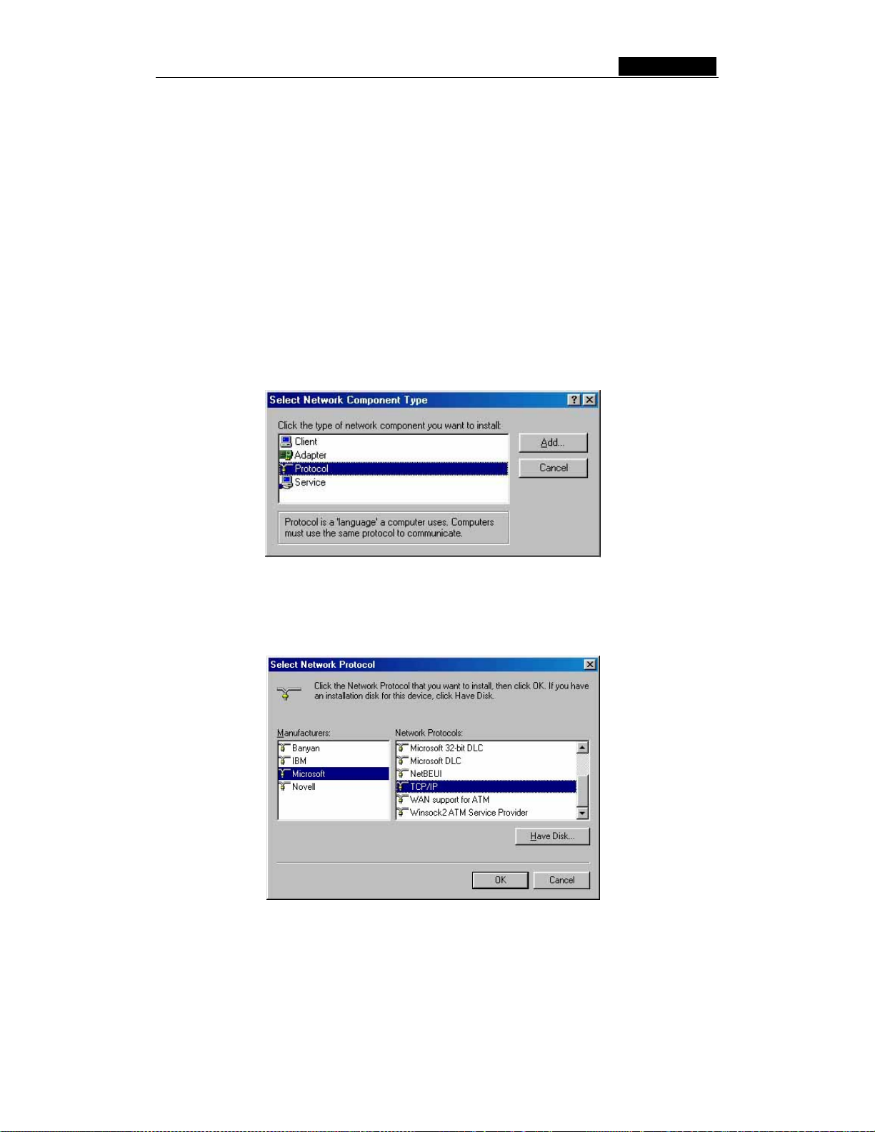
SMCWBR14-G3 User Guide
Appendix B: Configuring the PC
In this section, we’ll introduce how to install and configure the TCP/IP correctly in
Windows 95/98. First make sure your Ethernet Adapter is working, refer to the adapter’s
manual if needed.
1. Install TCP/IP component (If you use Windows 2000 or later, you can skip this
step.)
1) On the Windows taskbar, click the Start button, point to Settings, and then click
Control Panel.
2) Double-click the Network icon, click on the Configuration tab in the appearing
Network window.
3) Click on the Add button. Select Protocol, and then click Add.
Figure B-1: Add Network Protocol
4) Under Manufacturers on Select Network Pro tocol page, highlight Microsoft.
Under Network Protocols, highlight TCP/IP. Click OK. TCP/IP protocol will
take effect after reboot.
Figure B-2: Select Network Protocol
2. Configure TCP/IP for your computer
1) On the Windows taskbar, click the Start button, point to Settings, and then click
Control Panel.
2) Double-click the Network icon, highlight the bound TCP/IP tab in the appearing
- 66 -
Page 82
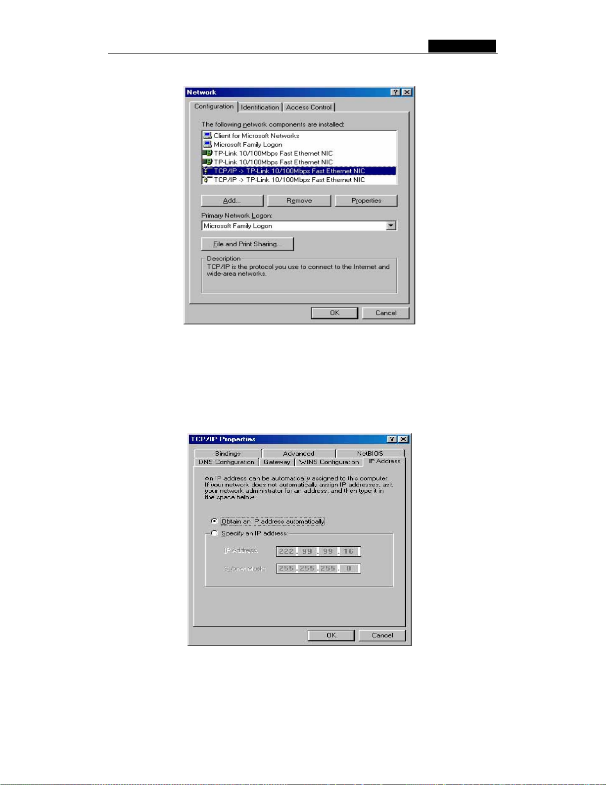
SMCWBR14-G3 User Guide
Network window that appears. An example is shown in the following figure:
Figure B-3: Configuration tab
3) Click on Properties. The following TCP/IP Properties window will display and
the IP Address tab is open on this window by default.
4) Now you have two ways to configure the TCP/IP protocol below:
• Assigned by DHCP Sever
a. Select Obtain an IP address automatically, as shown in the figure below:
Figure B-4: IP Address tab
b. Do not type anything into the New gateway field on the Gateway tab.
- 67 -
Page 83

SMCWBR14-G3 User Guide
Figure B-5: Gateway tab
c. Choose Disable DNS on the DNS configuration tab, as shown in the
following figure:
Figure B-6: DNS Configuration tab
• Setting IP address manually
a. Select Specify an IP address on IP Address tab, as shown in the following
figure. If the router's LAN IP address is 192.168.2.1, type IP address is
192.168.2.x (x is from 2 to 254), and subnet mask is 255.255.255.0.
- 68 -
Page 84

SMCWBR14-G3 User Guide
Figure B-7: IP Address tab
b. Type the router’s LAN IP address (the default IP is 192.168.2.1) into the
New gateway field on the Gateway tab, and click on the Add button, as
shown in the figure:
Figure B-8: Gateway tab
c. On the DNS Configuration tab, click Enable DNS radio, and type your
computer name in to the Host field and a Domain (such as szonline.com)
into the Domain field. In the DNS Server Search Order field you can type
the DNS server IP address, which has been provided by your ISP, and click
- 69 -
Page 85

Add button. Shown below:
Figure B-9: DNS Configuration tab
SMCWBR14-G3 User Guide
Now, all the configurations are finished, it will take effect after reboot.
- 70 -
Page 86

SMCWBR14-G3 User Guide
Appendix C: Specifications
General
Standards IEEE 802.3, 802.3u, 802.11b and 802.11g
Protocols TCP/IP, PPPoE, DHCP, ICMP, NAT, SNTP
Ports One 10/100M Auto-Negotiation WAN RJ45 port, Four 10/100M
Auto-Negotiation LAN RJ45 ports supporting Auto MDI/MDIX
Cabling Type 10BASE-T: UTP category 3, 4, 5 cable (maximum 100m)
EIA/TIA-568 100Ω STP (maximum 100m)
100BASE-TX: UTP category 5, 5e cable (maximum 100m)
EIA/TIA-568 100Ω STP (maximum 100m)
Radio Data Rate 54/48/36/24/18/12/9/6Mbps or 11/5.5/3/2/1Mbps
Power Supply 9V~ 0.8A
LEDs Power, SYS, WLAN, WAN, 1-4
Safety & Emissions FCC, CE
Environmental and Physica l
Operating Temp. 0~40 degrees C (32~104 degrees F)
Operating Humidity 10% - 95% RH, Non-condensing
Dimensions (W×D×H)
7.3×5.7×1.7 in. (186×146×44 mm) (without antenna)
- 71 -
Page 87

SMCWBR14-G3 User Guide
Appendix D: Glossary
¾ 802.11b - The 802.11b standard specifies a wireless networking at 11 Mbps using
direct-sequence spread-spectrum (DSSS) technology and operating in the
unlicensed radio spectrum at 2.4GHz, and WEP encryption for security. 802.11b
networks are also referred to as Wi-Fi networks.
¾ 802.11g - specification for wireless networking at 54 Mbps using direct-sequence
spread-spectrum (DSSS) technology, using OFDM modulation and operating in the
unlicensed radio spectrum at 2.4GHz, and backward compatibility with IEEE 802.11b
devices, and WEP encryption for security.
¾ DDNS (Dynamic Domain Name System) - The capability of assigning a fixed host
and domain name to a dynamic Internet IP Address.
¾ DHCP (Dynamic Host Configuration Protocol) - A protocol that automatically
configure the TCP/IP parameters for the all the PCs that are connected to a DHCP
server.
¾ DMZ (Demilitarized Zone) - A Demilitarized Zone allows one local host to be exposed
to the Internet for a special-purpose service such as Internet gaming or
videoconferencing.
¾ DNS (Domain Name System) – An Internet Service that translates the names of
websites into IP addresses.
¾ Domain Name - A descriptive name for an address or group of addresses on the
Internet.
¾ DoS (Denial of Service) - A hacker attack designed to prevent your computer or
network from operating or communicating.
¾ DSL (Digital Subscriber Line) - A technology that allows data to be sent or received
over existing traditional phone lines.
¾ ISP (Internet Service Provider) - A company that provides access to the Internet.
¾ MTU (Maximum Transmission Unit) - The size in bytes of the largest packet that
can be transmitted.
¾ NAT (Network Address Translation) - NAT technology translates IP addresses of a
local area network to a different IP address for the Internet.
¾ PPPoE (Point to Point Protocol over Ethernet) - PPPoE is a protocol for connecting
remote hosts to the Internet over an always-on connection by simulating a dial-up
connection.
¾ SSID - A Service Set Identification is a thirty-two character (maximum) alphanumeric
key identifying a wireless local area network. For the wireless devices in a network to
communicate with each other, all devices must be configured with the same SSID.
- 72 -
Page 88

SMCWBR14-G3 User Guide
This is typically the configuration parameter for a wireless PC card. It corresponds to
the ESSID in the wireless Access Point and to the wireless network name.
¾ WEP (Wired Equivalent Privacy) - A data privacy mechanism based on a 64-bit or
128-bit or 152-bit shared key algorithm, as described in the IEEE 802.11 standard.
¾ Wi-Fi - A trade name for the 802.11b wireless networking standard, given by the
Wireless Ethernet Compatibility Alliance (WECA, see http://www.wi-fi.net), an
industry standards group promoting interoperability among 802.11b devices.
¾ WLAN (Wireless Local Area Network) - A group of computers and associated
devices communicate with each other wirelessly, which network serving users are
limited in a local area.
- 73 -
Page 89

SMCWBR14-G3
SMCWBR11-G
 Loading...