

Page 1
Page 2

Page 3

Page 4

Page 5

C
OMPLIANCES
Federal Communication Commission Interference
Statement
This equipment has been tested and found to comply with the limits for a Class B digital
device, pursuant to Part 15 of the FCC Rules. These limits are designed to provide reasonable
protection against harmful interference in a residential installation. This equipment generates,
uses and can radiate radio frequency energy and, if not installed and used in accordance with
the instructions, may cause harmful interference to radio communications. However, there is
no guarantee that interference will not occur in a particular installation. If this equipment
does cause harmful interference to radio or television reception, which can be determined by
turning the equipment off and on, the user is encouraged to try to correct the interference by
one or more of the following measures:
• Reorient or relocate the receiving antenna.
• Increase the distance between the equipment and receiver.
• Connect the equipment into an outlet on a circuit different from that to which the receiver
is connected.
• Consult the dealer or an experienced radio/TV technician for help.
This device complies with Part 15 of the FCC Rules. Operation is subject to the following
two conditions: (1) This device may not cause harmful interference, and (2) this device must
accept any interference received, including interference that may cause undesired operation.
FCC Caution: Any changes or modifications not expressly approved by the party
responsible for compliance could void the user's authority to operate this equipment.
FCC Radiation Exposure Statement:
This equipment complies with FCC radiation exposure limits set forth for an uncontrolled
environment. This equipment should be installed and operated with a minimum distance of
20 cm between the radiator and your body.
This transmitter must not be co-located or operating in conjunction with any other antenna
or transmitter.
IMPORTANT NOTE:
IEEE 802.11b or 802.11g operation of this product in the U.S.A. is firmware-limited to
channels 1 through 11.
iii
Page 6

C
OMPLIANCES
Industry Canada Statement
Operation is subject to the following two conditions:
1. this device may not cause interference and
2. this device must accept any interference, including interference that may cause undesired
operation of the device
To prevent radio interference to the licensed service, this device is intended to be operated
indoors and away from windows to provide maximum shielding. Equipment (or its transmit
antenna) that is installed outdoors is subject to licensing.
This device has been designed to operate with an antenna having a maximum gain of 1.5 dBi.
Any antenna having a higher gain is strictly prohibited per regulations of Industry Canada.
The required antenna impedance is 50 ohms.
To reduce potential radio interference to other users, the antenna type and its gain should be
so chosen that the EIRP is not more than required for successful communication.
To prevent radio interference to the licensed service, this device is intended to be operated
indoors and away from windows to provide maximum shielding. Equipment (or its transmit
antenna) that is installed outdoors is subject to licensing.
EC Declaration of Conformity
SMC contact for these products in Europe is:
SMC Networks Europe,
Edificio Conata II,
Calle Fructuos Gelabert 6-8, 2o, 4a,
08970 - Sant Joan Despi,
Barcelona, Spain.
Marking by the above symbol indicates compliance with the Essential Requirements of the
R&TTE Directive of the European Union (1999/5/EC). This equipment meets the
following conformance standards:
EN 300 328-1 December 2001 V1.3.1
EN 300 328-2 December 2001 V1.2.1
EN 301 489-1 September 2001 V1.4.1
EN 301 489-17 September 2000 V1.2.1
EN 60950 January 2000
iv
Page 7

C
OMPLIANCES
Countries of Operation & Conditions of Use in the
European Community
This device is intended to be operated in all countries of the European Community.
Requirements for indoor vs. outdoor operation, license requirements and allowed channels of
operation apply in some countries as described below:
Note: The user must use the configuration utility provided with this product to ensure the
channels of operation are in conformance with the spectrum usage rules for European
Community countries as described below.
• This device requires that the user or installer properly enter the current country of
operation in the command line interface as described in the user guide, before operating
this device.
• This device will automatically limit the allowable channels determined by the current
country of operation. Incorrectly entering the country of operation may result in illegal
operation and may cause harmful interference to other system. The user is obligated to
ensure the device is operating according to the channel limitations, indoor/outdoor
restrictions and license requirements for each European Community country as described
in this document.
• This device may be operated indoors or outdoors in all countries of the European Community
using the 2.4 GHz band: Channels 1 - 13.
Declaration of Conformity in Languages of the
European Community
English Hereby, SMC Networks, declares that this Radio LAN device is in
compliance with the essential requirements and other relevant provisions
of Directive 1999/5/EC.
Finnish Valmistaja SMC Networks vakuuttaa täten että Radio LAN device
tyyppinen laite on direktiivin 1999/5/EY oleellisten vaatimusten ja sitä
koskevien direktiivin muiden ehtojen mukainen.
Dutch Hierbij verklaart SMC Networks dat het toestel Radio LAN device in
overeenstemming is met de essentiële eisen en de andere relevante
bepalingen van richtlijn 1999/5/EG
Bij deze SMC Networks dat deze Radio LAN device voldoet aan de
essentiële eisen en aan de overige relevante bepalingen van Richtlijn
1999/5/EC.
French Par la présente SMC Networks déclare que l'appareil Radio LAN device est
conforme aux exigences essentielles et aux autres dispositions pertinentes
de la directive 1999/5/CE
v
Page 8
C
OMPLIANCES
Swedish Härmed intygar SMC Networks att denna Radio LAN device står I
Danish Undertegnede SMC Networks erklærer herved, at følgende udstyr Radio
German Hiermit erklärt SMC Networks, dass sich dieser/diese/dieses Radio LAN
Greek
överensstämmelse med de väsentliga egenskapskrav och övriga relevanta
bestämmelser som framgår av direktiv 1999/5/EG.
LAN device overholder de væsentlige krav og øvrige relevante krav i
direktiv 1999/5/EF
device in Übereinstimmung mit den grundlegenden Anforderungen und
den anderen relevanten Vorschriften der Richtlinie 1999/5/EG befindet".
(BMWi)
Hiermit erklärt SMC Networks die Übereinstimmung des Gerätes Radio
LAN device mit den grundlegenden Anforderungen und den anderen
relevanten Festlegungen der Richtlinie 1999/5/EG. (Wien)
vi
Italian Con la presente SMC Networks dichiara che questo Radio LAN device è
conforme ai requisiti essenziali ed alle altre disposizioni pertinenti stabilite
dalla direttiva 1999/5/CE.
Spanish Por medio de la presente SMC Networks declara que el Radio LAN device
cumple con los requisitos esenciales y cualesquiera otras disposiciones
aplicables o exigibles de la Directiva 1999/5/CE
Portuguese SMC Networks declara que este Radio LAN device está conforme com os
requisitos essenciais e outras disposições da Directiva 1999/5/CE.
Page 9

C
OMPLIANCES
Safety Compliance
Underwriters Laboratories Compliance Statement
Important! Before making connections, make sure you have the correct cord set. Check it
(read the label on the cable) against the following:
Operating Voltage Cord Set Specifications
120 Volts UL Listed/CSA Certified Cord Set
Minimum 18 AWG
Type SVT or SJT three conductor cord
Maximum length of 15 feet
Parallel blade, grounding type attachment plug rated
15 A, 125 V
240 Volts (Europe only) Cord Set with H05VV-F cord having three conductors
The unit automatically matches the connected input voltage. Therefore, no additional
adjustments are necessary when connecting it to any input voltage within the range marked
on the power adapter.
with minimum diameter of 0.75 mm2
IEC-320 receptacle
Male plug rated 10 A, 250 V
Information for Power Source
This unit is to be used with a class 2 or level 3 external power adapter, approved suitable for
use in North American equipment installation, having an output voltage rating of 9 V DC,
and output current rating of 1.0 A or equivalent. The external AC adapter must be complied
with the requirements of LPS (Limited Power Sources).
N11846
vii
Page 10

C
OMPLIANCES
Wichtige Sicherheitshinweise (Germany)
1. Bitte lesen Sie diese Hinweise sorgfältig durch.
2. Heben Sie diese Anleitung für den späteren Gebrauch auf.
3. Vor jedem Reinigen ist das Gerät vom Stromnetz zu trennen. Verwenden Sie keine Flüssigoder Aerosolreiniger. Am besten eignet sich ein angefeuchtetes Tuch zur Reinigung.
4. Die Netzanschlu ßsteckdose soll nahe dem Gerät angebracht und leicht zugänglich sein.
5. Das Gerät ist vor Feuchtigkeit zu schützen.
6. Bei der Aufstellung des Gerätes ist auf sicheren Stand zu achten. Ein Kippen oder
Fallen könnte Beschädigungen hervorrufen.
7. Die Belüftungsöffnungen dienen der Luftzirkulation, die das Gerät vor Überhitzung
schützt. Sorgen Sie dafür, daß diese Öffnungen nicht abgedeckt werden.
8. Beachten Sie beim Anschluß an das Stromnetz die Anschlußwerte.
9. Verlegen Sie die Netzanschlußleitung so, daß niemand darüber fallen kann. Es sollte
auch nichts auf der Leitung abgestellt werden.
10. Alle Hinweise und Warnungen, die sich am Gerät befinden, sind zu beachten.
11. Wird das Gerät über einen längeren Zeitraum nicht benutzt, sollten Sie es vom Stromnetz trennen. Somit wird im Falle einer Überspannung eine Beschädigung vermieden.
12. Durch die Lüftungsöffnungen dürfen niemals Gegenstände oder Flüssigkeiten in das
Gerät gelangen. Dies könnte einen Brand bzw. elektrischen Schlag auslösen.
13. Öffnen sie niemals das Gerät. Das Gerät darf aus Gründen der elektrischen Sicherheit
nur von authorisiertem Servicepersonal geöffnet werden.
14. Wenn folgende Situationen auftreten ist das Gerät vom Stromnetz zu trennen und von
einer qualifizierten Servicestelle zu überprüfen:
a. Netzkabel oder Netzstecker sind beschädigt.
b. Flüssigkeit ist in das Gerät eingedrungen.
c. Das Gerät war Feuchtigkeit ausgesetzt.
d. Wenn das Gerät nicht der Bedienungsanleitung entsprechend funktioniert oder Sie mit
Hilfe dieser Anleitung keine Verbesserung erzielen.
e. Das Gerät ist gefallen und/oder das Gehäuse ist beschädigt.
f. Wenn das Gerät deutliche Anzeichen eines Defektes aufweist.
15. Stellen Sie sicher, daß die Stromversorgung dieses Gerätes nach der EN 60950 geprüft
ist. Ausgangswerte der Stromversorgung sollten die Werte von AC 7,5-8 V, 50-60 Hz
nicht über oder unterschreiten sowie den minimalen Strom von 1 A nicht unterschreiten.
Der arbeitsplatzbezogene Schalldruckpegel nach DIN 45 635 Teil 1000 beträgt 70 dB(A)
oder weniger.
viii
Page 11

T
ABLE OF
C
ONTENTS
1 Introduction . . . . . . . . . . . . . . . . . . . . . . . . . . . . . . . . . .1-1
About the BARRICADE . . . . . . . . . . . . . . . . . . . . . . . . . . . . . . . . . . . . . 1-1
Features and Benefits . . . . . . . . . . . . . . . . . . . . . . . . . . . . . . . . . . . . . . . . 1-2
Applications . . . . . . . . . . . . . . . . . . . . . . . . . . . . . . . . . . . . . . . . . . . . . . . 1-3
2 Installation . . . . . . . . . . . . . . . . . . . . . . . . . . . . . . . . . . 2-1
Package Contents . . . . . . . . . . . . . . . . . . . . . . . . . . . . . . . . . . . . . . . . . . . 2-1
System Requirements . . . . . . . . . . . . . . . . . . . . . . . . . . . . . . . . . . . . . . . . 2-2
Hardware Description . . . . . . . . . . . . . . . . . . . . . . . . . . . . . . . . . . . . . . . 2-2
ISP Settings . . . . . . . . . . . . . . . . . . . . . . . . . . . . . . . . . . . . . . . . . . . . . . . . 2-5
Connect the System . . . . . . . . . . . . . . . . . . . . . . . . . . . . . . . . . . . . . . . . . 2-5
Desktop Installation . . . . . . . . . . . . . . . . . . . . . . . . . . . . . . . . . . . 2-5
Wall-Mount Installation . . . . . . . . . . . . . . . . . . . . . . . . . . . . . . . . 2-6
Connecting the BARRICADE to your LAN . . . . . . . . . . . . . . . 2-7
Connect the Power Adapter . . . . . . . . . . . . . . . . . . . . . . . . . . . . . 2-7
Application Example . . . . . . . . . . . . . . . . . . . . . . . . . . . . . . . . . . . . . . . . 2-8
3 Configuring The Client PC . . . . . . . . . . . . . . . . . . . . . 3-1
TCP/IP Configuration . . . . . . . . . . . . . . . . . . . . . . . . . . . . . . . . . . . . . . . 3-2
Windows 2000 . . . . . . . . . . . . . . . . . . . . . . . . . . . . . . . . . . . . . . . 3-3
Obtain IP Settings From Your BARRICADE . . . . . . . . . . . . . . 3-5
Manual IP Configuration . . . . . . . . . . . . . . . . . . . . . . . . . . . . . . . 3-7
Windows XP . . . . . . . . . . . . . . . . . . . . . . . . . . . . . . . . . . . . . . . . . 3-9
Disable HTTP Proxy . . . . . . . . . . . . . . . . . . . . . . . . . . . . . . . . . 3-14
Configuring Your Macintosh Computer . . . . . . . . . . . . . . . . . . . . . . . . 3-15
Disable HTTP Proxy . . . . . . . . . . . . . . . . . . . . . . . . . . . . . . . . . 3-17
4 Configuring the BARRICADE . . . . . . . . . . . . . . . . . . 4-1
Navigating the Web Browser Interface . . . . . . . . . . . . . . . . . . . . . . . . . . 4-2
Making Configuration Changes . . . . . . . . . . . . . . . . . . . . . . . . . . 4-3
Login Screen . . . . . . . . . . . . . . . . . . . . . . . . . . . . . . . . . . . . . . . . . . . . . . . 4-4
Setup Wizard . . . . . . . . . . . . . . . . . . . . . . . . . . . . . . . . . . . . . . . . . . . . . . 4-5
Getting Started . . . . . . . . . . . . . . . . . . . . . . . . . . . . . . . . . . . . . . . 4-5
Wireless Settings . . . . . . . . . . . . . . . . . . . . . . . . . . . . . . . . . . . . . . 4-6
Internet Settings . . . . . . . . . . . . . . . . . . . . . . . . . . . . . . . . . . . . . . 4-8
ix
Page 12

T
ABLE OF CONTENTS
Home Network Settings . . . . . . . . . . . . . . . . . . . . . . . . . . . . . . . . . . . . 4-14
Status . . . . . . . . . . . . . . . . . . . . . . . . . . . . . . . . . . . . . . . . . . . . . . 4-15
LAN Settings . . . . . . . . . . . . . . . . . . . . . . . . . . . . . . . . . . . . . . . 4-17
WAN Settings . . . . . . . . . . . . . . . . . . . . . . . . . . . . . . . . . . . . . . . 4-19
Wireless . . . . . . . . . . . . . . . . . . . . . . . . . . . . . . . . . . . . . . . . . . . . 4-25
Security . . . . . . . . . . . . . . . . . . . . . . . . . . . . . . . . . . . . . . . . . . . . . . . . . . 4-29
Firewall . . . . . . . . . . . . . . . . . . . . . . . . . . . . . . . . . . . . . . . . . . . . 4-30
Wireless . . . . . . . . . . . . . . . . . . . . . . . . . . . . . . . . . . . . . . . . . . . . 4-44
Advanced Settings . . . . . . . . . . . . . . . . . . . . . . . . . . . . . . . . . . . . . . . . . 4-53
NAT . . . . . . . . . . . . . . . . . . . . . . . . . . . . . . . . . . . . . . . . . . . . . . 4-54
Maintenance . . . . . . . . . . . . . . . . . . . . . . . . . . . . . . . . . . . . . . . . 4-60
System . . . . . . . . . . . . . . . . . . . . . . . . . . . . . . . . . . . . . . . . . . . . . 4-63
UPnP . . . . . . . . . . . . . . . . . . . . . . . . . . . . . . . . . . . . . . . . . . . . . . 4-68
DNS (Domain Name Server) . . . . . . . . . . . . . . . . . . . . . . . . . . . 4-69
DDNS (Dynamic DNS) . . . . . . . . . . . . . . . . . . . . . . . . . . . . . . . 4-70
Routing . . . . . . . . . . . . . . . . . . . . . . . . . . . . . . . . . . . . . . . . . . . . 4-71
A Troubleshooting . . . . . . . . . . . . . . . . . . . . . . . . . . . . . .A-1
B Cables . . . . . . . . . . . . . . . . . . . . . . . . . . . . . . . . . . . . . .B-1
Ethernet Cable . . . . . . . . . . . . . . . . . . . . . . . . . . . . . . . . . . . . . . . . . . . . . B-1
Specifications . . . . . . . . . . . . . . . . . . . . . . . . . . . . . . . . . . . . . . . . B-1
Wiring Conventions . . . . . . . . . . . . . . . . . . . . . . . . . . . . . . . . . . . B-1
RJ-45 Port Ethernet Connection . . . . . . . . . . . . . . . . . . . . . . . . . . . . . . . B-2
Pin Assignments . . . . . . . . . . . . . . . . . . . . . . . . . . . . . . . . . . . . . . B-3
C Specifications . . . . . . . . . . . . . . . . . . . . . . . . . . . . . . . .C-1
x
Page 13

C
HAPTER
I
NTRODUCTION
Congratulations on your purchase of the BARRICADE 54Mbps g
Wireless Broadband Router (SMCWBR14-G2). We are proud to provide
you with a powerful yet simple communication device for connecting your
local area network (LAN) to the Internet. For those who want to surf the
Internet in the most secure way, this router provides a convenient and
powerful solution.
About the BARRICADE
The BARRICADE provides Internet access to multiple users by sharing a
single-user account. This new technology provides many secure and
cost-effective functions. It is simple to configure and can be up and
running in minutes.
1
1-1
Page 14

F
EATURES AND BENEFITS
Features and Benefits
• Local network connection via a 10/100 Mbps Ethernet port
• DHCP for dynamic IP configuration, and DNS for domain name
mapping
• Firewall with Stateful Packet Inspection, client privileges, intrusion
detection, and NAT
• NAT also enables multi-user Internet access via a single user account,
and virtual server functionality (providing protected access to Internet
services such as web, FTP, email, and Telnet)
• VPN pass-through (IPSec-ESP Tunnel mode, L2TP, PPTP)
• User-definable application sensing tunnel supports applications
requiring multiple connections
• Easy setup through a web browser on any operating system that
supports TCP/IP
• Compatible with all popular Internet applications
1-2
Page 15

Applications
Many advanced networking features are provided by this BARRICADE:
• Wired and Wireless LAN
The BARRICADE provides connectivity to 10/100 Mbps devices,
and wireless IEEE 802.11g compatible devices, making it easy to
create a network in small offices or homes.
• Internet Access
This device supports Internet access through an ADSL connection.
Since many ADSL providers use PPPoE or PPPoA to establish
communications with end users, the BARRICADE includes built-in
clients for these protocols, eliminating the need to install these
services on your computer.
• Shared IP Address
The BARRICADE provides Internet access for up to 253 users via a
single shared IP address. Using only one ISP account, multiple users
on your network can browse the web at the same time.
I
NTRODUCTION
•Virtual Server
If you have a fixed IP address, you can set the BARRICADE to act as
a virtual host for network address translation. Remote users access
various services at your site using a constant IP address. Then,
depending on the requested service (or port number), the
BARRICADE can route the request to the appropriate server (at
another internal IP address). This secures your network from direct
attack by hackers, and provides more flexible management by allowing
you to change internal IP addresses without affecting outside access
to your network.
1-3
Page 16

A
PPLICATIONS
• DMZ Host Support
Allows a networked computer to be fully exposed to the Internet.
This function is used when NAT and firewall security prevent an
Internet application from functioning correctly.
• Security
The BARRICADE supports security features that deny Internet
access to specified users, or filter all requests for specific services that
the administrator does not want to serve. The BARRICADE’s firewall
also blocks common hacker attacks, including IP Spoofing, Land
Attack, Ping of Death, IP with zero length, Smurf Attack, UDP port
loopback, Snork Attack, TCP null scan, and TCP SYN flooding.
WPA/WPA2, WEP, SSID, and MAC filtering provide security over
the wireless network.
• Virtual Private Network (VPN Pass-through)
The BARRICADE supports three of the most commonly used VPN
protocols – PPTP, L2TP, and IPSec. The VPN protocols supported
by the BARRICADE are briefly described below.
1-4
• Point-to-Point Tunneling Protocol – Provides a secure tunnel for
remote client access to a PPTP security gateway. PPTP includes
provisions for call origination and flow control required by ISPs.
• L2TP merges the best features of PPTP and L2F – Like PPTP,
L2TP requires that the ISP’s routers support the protocol.
• IP Security – Provides IP network-layer encryption. IPSec can
support large encryption networks (such as the Internet) by using
digital certificates for device authentication.
Page 17

C
HAPTER
I
NSTALLATION
Before installing the BARRICADE, verify that you have all the items listed
under “Package Contents.” If any of the items are missing or damaged,
contact your local distributor. Also be sure that you have all the necessary
cabling before installing the BARRICADE. After installing the
BARRICADE, refer to “Configuring the BARRICADE” on page 4-1.
Package Contents
After unpacking the BARRICADE, check the contents of the box to be
sure you have received the following components:
• BARRICADE 54Mbps g Wireless Broadband Router
(SMCWBR14-G2)
• Power adapter
2
• One CAT-5 Ethernet cable (RJ-45)
• One documentation CD
•Quick Install Guide
Immediately inform your dealer in the event of any incorrect, missing, or
damaged parts. If possible, please retain the carton and original packing
materials in case there is a need to return the product.
2-1
Page 18

I
NSTALLATION
System Requirements
You must meet the following minimum requirements:
• Internet access from your local telephone company or Internet Service
Provider (ISP) using a DSL modem or cable modem.
• A computer with a CD-ROM drive
• Windows (98 or later), MacOS (9.x)
• An up to date web browser:
• Internet Explorer 5.5 or later
• Mozilla 1.7/Firefox 1.0 or later
Hardware Description
The BARRICADE connects to the Internet or to a remote site using its
WAN RJ-45 port linked to a modem. It also can be connected directly to
your PC or to a local area network using the Fast Ethernet LAN port.
Access speed to the Internet depends on your service type. Full-rate ADSL
provides up to 8 Mbps downstream and 1 Mbps upstream. G.lite (or
splitterless) ADSL provides up to 1.5 Mbps downstream and 512 kbps
upstream. However, you should note that the actual rate provided by
specific service providers may vary dramatically from these upper limits.
Data passing between devices connected to your local area network can
run at up to 100 Mbps over the Fast Ethernet port and 54 Mbps over the
built-in wireless network adapter.
The BARRICADE includes an LED display on the front panel for system
power and port indications that simplifies installation and network
troubleshooting.
2-2
Page 19
H
ARDWARE DESCRIPTION
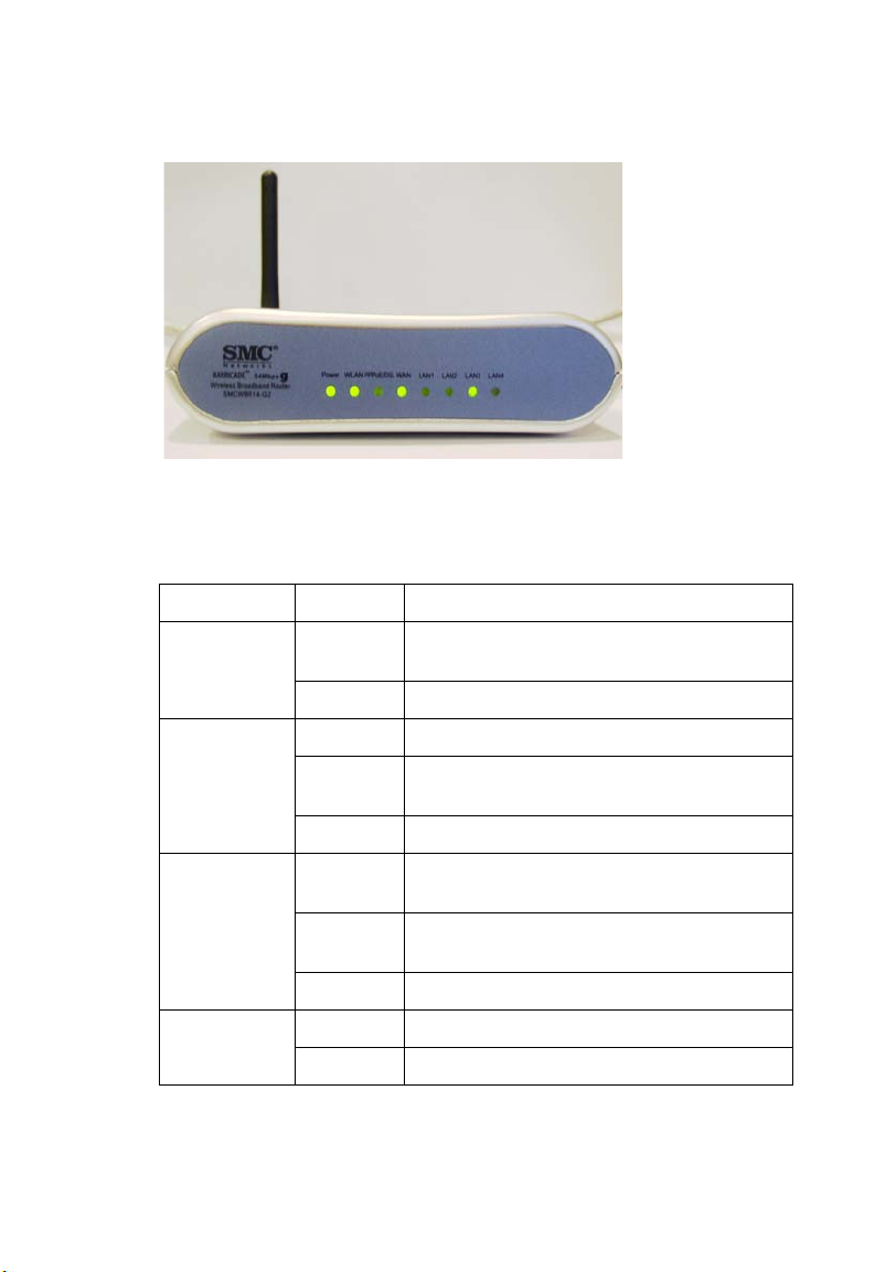
Figure 2-1. Front LED indicators
The power and port LED indicators on the front panel are illustrated by
the following table.
LED Status Description
Power On The BARRICADE is receiving power. Normal
operation.
Off Power off or failure.
WLAN On WLAN link.
Flashing The BARRICADE is sending or receiving data
via WLAN.
Off No WLAN link.
PPPoE/DSL On PPPoE/DSL connection is functioning
correctly.
Flashing The BARRICADE is sending or receiving data
via PPPoE/DSL link.
Off PPPoE/DSL connection is not established.
WAN On WAN link.
Off No WAN link.
2-3
Page 20
I
NSTALLATION
LED Status Description
LAN 1~4 On Ethernet link.
Flashing The LAN port is sending or receiving data.
Off No Ethernet link.
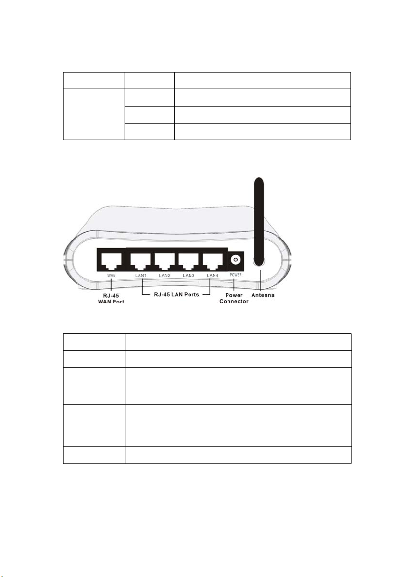
The following figure and table shows the rear panel of the BARRICADE.
Figure 2-2. Rear Panel
2-4
Item Description
WAN Port Connect your WAN line to this port. (RJ-45)
LAN Ports Fast Ethernet ports (RJ-45). Connect devices on your local
area network to these ports (i.e., a PC, hub, switch or IP set
top box).
Power Inlet Connect the included power adapter to this inlet.
Warning: Using the wrong type of power adapter may cause
damage.
Antenna Antenna is connected here.
Page 21

ISP Settings
Please collect the following information from your ISP before setting up
the BARRICADE:
• ISP account user name and password
• Protocol, encapsulation and VPI/VCI circuit numbers
•DNS server address
• IP address, subnet mask and default gateway (for fixed IP users only)
Connect the System
Desktop Installation
The BARRICADE can be positioned on any convenient flat surface in
your office or home. No special wiring or cooling requirements are
needed. You should, however, comply with the following guidelines:
• Keep the BARRICADE away from any heating devices.
ISP S
ETTINGS
• Do not place the BARRICADE in a dusty or wet environment.
You should also remember to turn off the power, remove the power cord
from the outlet, and keep your hands dry when you install the
BARRICADE.
2-5
Page 22
I
NSTALLATION
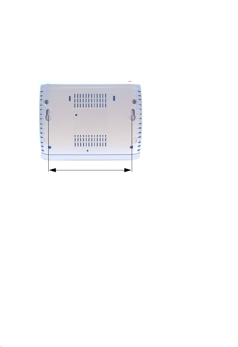
Wall-Mount Installation
There are two wall-mount holes at the bottom of the BARRICADE.
Before drilling two holes into the wall, make sure the holes are 87 mm
apart.
87 mm
1. Choose a suitable location for the BARRICADE.
Note: It should be accessible for installing, cabling and maintaining the
device.
2. Measure the distance of the two wall-mount holes.
3. Drill two holes into the wall.
4. Insert a screw into each hole.
Note: Leave 5 mm exposed of the screw head.
5. Attach the BARRICADE to the wall with two wall-mount slots, and
then slide the device down until the screws fit firmly into the slots of
the device.
2-6
Page 23

C
ONNECT THE SYSTEM
Connecting the BARRICADE to your LAN
The four LAN ports on the BARRICADE auto-negotiate the connection
speed to 10 Mbps Ethernet or 100 Mbps Fast Ethernet, as well as the
transmission mode to half duplex or full duplex.
Use RJ-45 cables to connect any of the four LAN ports on the
BARRICADE to an Ethernet adapter on your PC. Otherwise, cascade any
of the LAN ports on the BARRICADE to an Ethernet hub or switch, and
then connect your PC or other network equipment to the hub or switch.
When inserting an RJ-45 connector, be sure the tab on the connector
clicks into position to ensure that it is properly seated.
Warning: Do not plug a phone jack connector into an RJ-45 port. This
may damage the BARRICADE. Instead, use only twisted-pair
cables with RJ-45 connectors that conform with FCC
standards.
Notes: 1. Use 100-ohm shielded or unshielded twisted-pair cable with RJ-
45 connectors for all Ethernet ports. Use Category 3, 4, or 5 for
connections that operate at 10 Mbps, and Category 5 for
connections that operate at 100 Mbps.
2. Make sure each twisted-pair cable length does not exceed
100 meters (328 feet).
Connect the Power Adapter
Plug the power adapter into the power socket on the side panel of the
BARRICADE, and the other end into a power outlet.
Check the power indicator on the front panel is lit. If the power i
not lit, refer to
In case of a power input failure, the BARRICADE will automatically
restart and begin to operate once the input power is restored.
If the
BARRICADE
establish a connection with the ADSL service provider after powering up.
“Troubleshooting” on page A-1.
is properly configured, it will take about 30 seconds to
ndicator is
2-7
Page 24
I
NSTALLATION
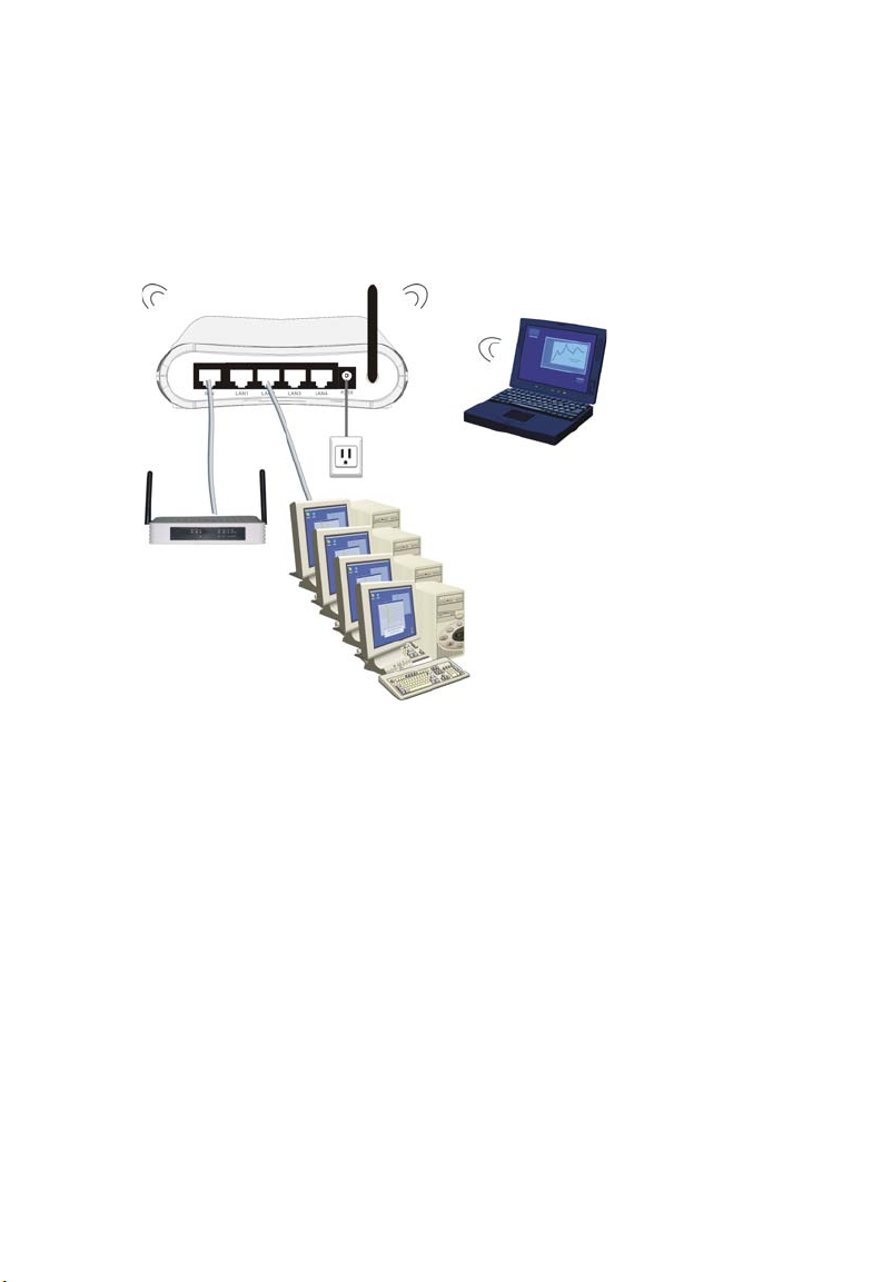
Application Example
The following diagram shows a typical network application.
2-8
Page 25

C
HAPTER
C
ONFIGURING
C
LIENT
After completing hardware setup by connecting all your network devices,
you need to configure your computer to connect to the BARRICADE.
You can either configure your computer to automatically obtain IP settings
(DHCP) or manually configure IP address settings (Static IP).
Depending on your operating system see:
“Windows 2000” on page 3-3,
“Windows XP” on page 3-9,
or
“Configuring Your Macintosh Computer” on page 3-15.
T
3
HE
PC
3-1
Page 26

TCP/IP C
ONFIGURATION
TCP/IP Configuration
To access the Internet through the BARRICADE, you must configure the
network settings of the computers on your LAN to use the same IP subnet
as the BARRICADE. The default network settings for the BARRICADE
are:
IP Address: 192.168.2.1
Subnet Mask: 255.255.255.0
Note: These settings can be changed to fit your network requirements,
but you must first configure at least one computer to access the
BARRICADE’s web configuration interface in order to make the
required changes. (See “Configuring the BARRICADE” on page
4-1 for instructions on configuring the BARRICADE.)
3-2
Page 27
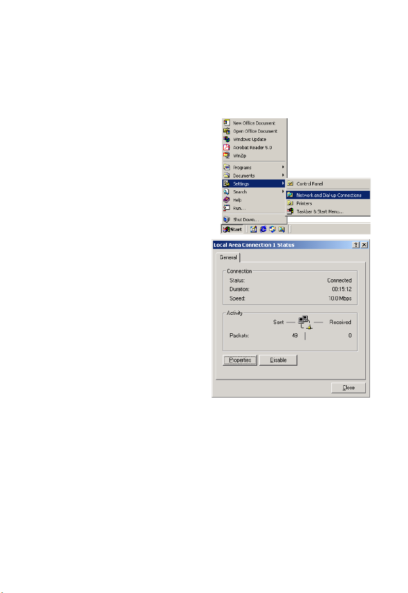
Windows 2000
DHCP IP Configuration
1. On the Windows desktop,
click Start/Settings/
Network and Dial-Up
Connections.
2. Click the icon that
corresponds to the
connection to your
BARRICADE.
3. The connection status
screen will open. Click
Properties.
C
ONFIGURING THE CLIENT
PC
3-3
Page 28
TCP/IP C
ONFIGURATION
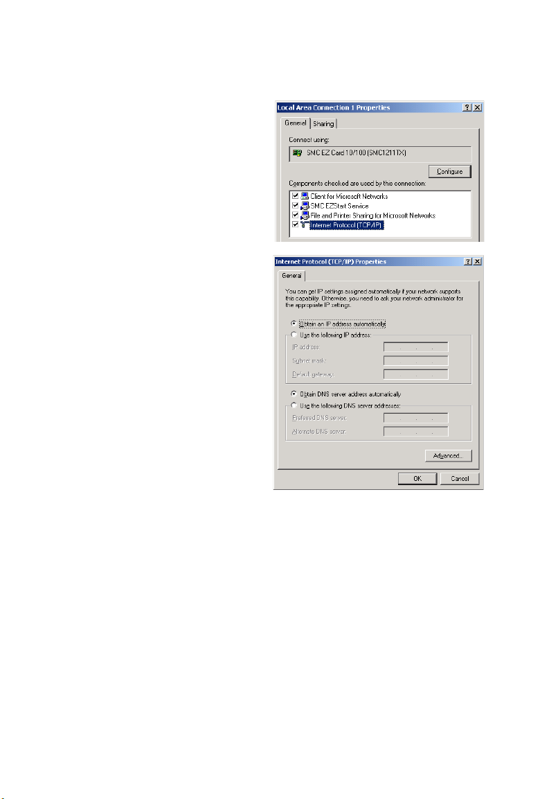
4. Double-click Internet
Protocol (TCP/IP).
5. If Obtain an IP address
automatically and Obtain
DNS server address
automatically are already
selected, your computer is
already configured for
DHCP. If not, select these
options now and click OK.
3-4
Page 29
C
ONFIGURING THE CLIENT
Obtain IP Settings From Your BARRICADE
Now that you have configured your computer to connect to your
BARRICADE, it needs to obtain new network settings. By releasing old
DHCP IP settings and renewing them with settings from your
BARRICADE, you can verify that you have configured your computer
correctly.
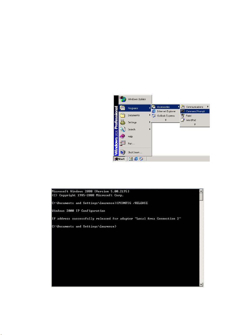
1. On the Windows desktop,
click Start/Programs/
Accessories/Command
Prompt.
2. In the Command Prompt window, type “IPCONFIG /RELEASE”
and press the Enter key.
PC
3-5
Page 30
TCP/IP C
ONFIGURATION
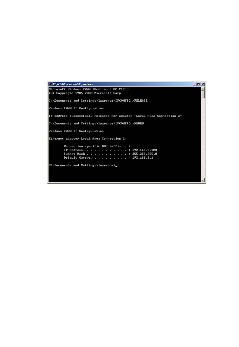
3. Type “IPCONFIG /RENEW” and press the Enter key. Verify that
your IP Address is now 192.168.2.xxx, your Subnet Mask is
255.255.255.0 and your Default Gateway is 192.168.2.1. These values
confirm that your BARRICADE is functioning correctly.
4. Type “EXIT” and press the Enter key to close the Command Prompt
window.
3-6
Page 31

C
ONFIGURING THE CLIENT
Manual IP Configuration
1. Follow steps 1-4 in “DHCP IP Configuration” on page 3-3.
2. Select Use the
following IP address.
Enter an IP address
based on the default
network 192.168.2.x
(where x is
and 254), and use
255.255.255.0
subnet mask. Use
192.168.2.1 for the
Default gateway field.
3. Select Use the
following DNS server
addresses.
4.
Enter the IP address for the
field
provided by your ISP. Otherwise, add a specific
Alternate DNS Server field and click
between 2
for the
BARRICADE
. This automatically relays DNS requests to the DNS server(s)
in the Preferred DNS server
OK
to close the dialog boxes
PC
DNS server into the
.
5. Record the configured information in the following table.
TCP/IP Configuration Setting
IP Address ____.____.____.____
Subnet Mask ____.____.____.____
Preferred DNS Server ____.____.____.____
Alternate DNS Server ____.____.____.____
Default Gateway ____.____.____.____
3-7
Page 32

TCP/IP C
ONFIGURATION
Disable HTTP Proxy
You need to verify that the “HTTP Proxy” feature of your web browser is
disabled. This is so that your browser can view the BARRICADE’s HTML
configuration pages.
1. To disable the proxy in
Internet Explorer, click
To ol s. Click Internet
Options... and then
the Connections tab,
shown on the right.
the Local Area Network
(LAN) settings section,
click
LAN Settings...
to display the Local
Area Network (LAN)
Settings pop-up window
below.
In
2. In the Proxy server
section, ensure the Use
a proxy server for
your LAN (These
settings will not apply
to dial-up or VPN
connections) check
box is not ticked.
3. Click OK.
3-8
Page 33

Windows XP
DHCP IP Configuration
1. On the Windows desktop,
click Start/Control Panel.
2. In the Control Panel window,
click Network and Internet
Connections.
3. The Network Connections
window will open. Locate and
double-click the Local Area
Connection icon for the
Ethernet adapter that is
connected to the BARRICADE.
C
ONFIGURING THE CLIENT
PC
4. In the connection status screen,
click Properties.
3-9
Page 34

TCP/IP C
ONFIGURATION
5. Double-click Internet
Protocol (TCP/IP).
6. If Obtain an IP address
automatically and Obtain
DNS server address
automatically are already
selected, your computer is
already configured for DHCP.
If not, select these options
now and click OK.
3-10
Page 35

C
ONFIGURING THE CLIENT
Obtain IP Settings From Your BARRICADE
Now that you have configured your computer to connect to your
BARRICADE, it needs to obtain new network settings. By releasing old
DHCP IP settings and renewing them with settings from your
BARRICADE, you can verify that you have configured your computer
correctly.
1. On the Windows desktop, click Start/Programs/Accessories/
Command Prompt.
PC
2. In the Command Prompt window, type “IPCONFIG /RELEASE”
and press the Enter key.
3-11
Page 36

TCP/IP C
ONFIGURATION
3. Type “IPCONFIG /RENEW” and press the Enter key. Verify that
your IP Address is now 192.168.2.xxx, your Subnet Mask is
255.255.255.0 and your Default Gateway is 192.168.2.1. These values
confirm that your BARRICADE is functioning correctly.
4. Type “EXIT” and press the Enter key to close the Command Prompt
window.
Your computer is now configured to connect to the BARRICADE.
3-12
Page 37

C
ONFIGURING THE CLIENT
Manual IP Configuration
1. Follow steps 1-5 in “DHCP IP Configuration” on page 3-9.
2. Select Use the following IP
Address.
3. Enter an IP address based on
the default network
192.168.2.x (where x is
between 2 and 254), and use
255.255.255.0
mask. Use
for the subnet
192.168.2.1 for the
Default gateway field.
4. Select Use the following
DNS server addresses.
5. Enter the IP address for the BARRICADE in the Preferred DNS
server field. This automatically relays DNS requests to the DNS
server(s) provided by your ISP. Otherwise, add a specific DNS server
into the Alternate DNS Server field and click OK to close the dialog
boxes.
PC
6. Record the configured information in the following table.
TCP/IP Configuration Setting
IP Address ____.____.____.____
Subnet Mask ____.____.____.____
Preferred DNS Server ____.____.____.____
Alternate DNS Server ____.____.____.____
Default Gateway ____.____.____.____
3-13
Page 38

TCP/IP C
ONFIGURATION
Disable HTTP Proxy
You need to verify that the “HTTP Proxy” feature of your web browser is
disabled. This is so that your browser can view the BARRICADE’s HTML
configuration pages.
1. To disable the proxy in
Internet Explorer, click
To ol s. Click Internet
Options... and then
the Connections tab,
shown on the right.
the Local Area Network
(LAN) settings section,
click
LAN Settings...
to display the Local
Area Network (LAN)
Settings pop-up window
below.
In
2. In the Proxy server
section, ensure the Use
a proxy server for
your LAN (These
settings will not apply
to dial-up or VPN
connections) check
box is not ticked.
3. Click OK.
3-14
Page 39

C
ONFIGURING THE CLIENT
Configuring Your Macintosh Computer
You may find that the instructions here do not exactly match your
operating system. This is because these steps and screen shots were created
using Mac OS 10.2. Mac OS 7.x and above are similar, but may not be
identical to Mac OS 10.2.
Follow these instructions:
1. Pull down the Apple Menu . Click
System Preferences.
2. Double-click the Network icon in the
Systems Preferences window.
PC
3-15
Page 40

C
ONFIGURING YOUR MACINTOSH COMPUTER
3. If Using DHCP Server is
already selected in the
Configure field, your
computer is already
configured for DHCP. If
not, select this option.
4. Your new settings are shown in the TCP/IP tab. Verify that your IP
Address is now 192.168.2.xxx, your Subnet Mask is 255.255.255.0 and
your Default Gateway is 192.168.2.1. These values confirm that your
BARRICADE is functioning.
5. Close the Network window.
Now your computer is configured to connect to the BARRICADE.
3-16
Page 41

C
ONFIGURING THE CLIENT
Disable HTTP Proxy
You need to verify that the “HTTP Proxy” feature of your web browser is
disabled. This is so that your browser can view the BARRICADE’s HTML
configuration pages. The following steps are for Internet Explorer.
Internet Explorer
1. Open Internet Explorer and click the Stop
button. Click Explorer/Preferences.
2. In the Internet Explorer Preferences window,
under Network, select Proxies.
3. Uncheck all check boxes and click OK.
PC
3-17
Page 42

C
ONFIGURING YOUR MACINTOSH COMPUTER
3-18
Page 43

C
HAPTER
C
ONFIGURING THE
4
BARRICADE
After you have configured TCP/IP on a client computer, use a web
browser to configure the BARRICADE. The BARRICADE can be
configured by any Java-supported browser such as Internet Explorer 5.5 or
above. Using the web management interface, you can configure the
BARRICADE and view statistics to monitor network activity.
To access the BARRICADE’s management interface, enter the IP address
of the BARRICADE in your web browser:
http://192.168.2.1
(The BARRICADE automatically switches to Port 80 for management
access.)
4-1
Page 44

C
ONFIGURING THE
BARRICADE
Navigating the Web Browser Interface
The BARRICADE’s management interface consists of a Setup Wizard,
a Home Network Settings section, a Security section and an Advanced
Settings section.
Setup Wizard: Use the Setup Wizard for quick and easy configuration of
your Internet connection and basic LAN settings. Go to “Setup Wizard”
on page 4-5.
Home Network Settings: Use the Home Network Settings section to
configure your LAN, WAN and wireless settings. Go to “Home Network
Settings” on page 4-14.
Security: In this section, you can easily configure your wireless security
settings. Go to “Security” on page 4-29.
Advanced Settings: Advanced Settings supports more advanced
functions like NAT, system maintenance and UPnP. Go to “Advanced
Settings” on page 4-53.
4-2
Page 45

N
AVIGATING THE WEB BROWSER INTERFACE
Making Configuration Changes
Configurable parameters have a dialog box or a drop-down list. Once
a configuration change has been made on a page, be sure to click the
Apply or Save Settings or NEXT button at the bottom of the page to
enable the new setting.
Note: To ensure proper screen refresh after a command entry, be sure
that Internet Explorer 5.5 is configured as follows: Under the
menu Tools/Internet Options.../General/Temporary Internet
Files/Settings..., the setting for Check for newer versions of
stored pages should be Every visit to the page.
4-3
Page 46

C
ONFIGURING THE
BARRICADE
Login Screen
The Login screen automatically appears first.
Enter the default password “smcadmin” and then click LOGIN.
Note: Your password is case sensitive.
4-4
Page 47

S
Setup Wizard
Getting Started
The Setup Wizard automatically appears by clicking on the Setup Wizard
button of the left-hand menu. The first item in the Setup Wizard is Getting
Started.
ETUP WIZARD
Simply click NEXT to proceed to the following screen and configure your
Wireless Settings.
4-5
Page 48

C
ONFIGURING THE
BARRICADE
Wireless Settings
Enter your wireless network settings on this page. You must specify
a common radio channel and SSID (Service Set ID) to be used by the
BARRICADE and all of its wireless clients. Be sure you configure all of its
clients to the same value. For security purposes, you should change the
default SSID immediately.
Parameter Description
Wireless Network
Name (SSID)
Broadcast Wireless
Network Name
Wireless Mode This device supports the following modes: 11g only, 11b
The Service Set ID (SSID) is the name of your wireless
network. The SSID must be the same on the
BARRICADE and all of its wireless clients.
(Default: SMC)
Enable or disable the broadcasting of the SSID. If you
disable broadcast of the SSID, only devices that have the
correct SSID can connect. This nullifies the wireless
network “discovery” feature of some products such as
Windows XP. (Default: Enable)
only, and 11b/g mixed mode.
(Default: 11b/g Mixed mode)
4-6
Page 49

S
Parameter Description
Wi-Fi Channel
Number
Extend Range Increases the range of the BARRICADE.
The radio channel used by the BARRICADE and its
clients to communicate with each other. This channel
must be the same on the BARRICADE and all of its
wireless clients.
The BARRICADE will automatically assign itself a radio
channel, or you may select one manually.
(Default channel: 6)
(Default: Disable)
ETUP WIZARD
4-7
Page 50

C
ONFIGURING THE
BARRICADE
Internet Settings
Specify the WAN connection type required by your Internet Service
Provider. Specify Cable modem, Fixed-IP xDSL, PPPoE xDSL, PPTP or
BigPond.
Select your connection type to proceed. Click BACK to go back and
change your settings.
4-8
Page 51

S
ETUP WIZARD
Cable Modem Settings
If the ISP requires you to input a Host Name, type it in the Host Name
field. The MAC Address field will be filled automatically.
Click NEXT to proceed, or BACK to change your settings.
4-9
Page 52

C
ONFIGURING THE
ADSL Settings - Fixed-IP xDSL
Enter the IP address, Subnet Mask, and Gateway IP address provided to
you by your ISP in the appropriate fields below.
Click NEXT to proceed, or BACK to change your settings.
BARRICADE
4-10
Page 53

S
ETUP WIZARD
ADSL Settings - PPPoE
Enter the User Name and Password required by your ISP in the
appropriate fields. If your ISP has provided you with a Service Name enter
it in the Service Name field, otherwise, leave it blank. Leave the Maximum
Transmission Unit (MTU) at the default value (1454) unless you have
a particular reason to change it. Enter the maximum idle time for the
Internet connection. After this time has been exceeded the connection will
be terminated. Check Keep session to keep the session alive. Check the
Auto-connect check box to automatically re-establish the connection as
soon as you attempt to access the Internet again. Check the Manual-
connect check box to manually re-establish the connection.
Click NEXT to proceed, or BACK to change your settings.
Note: Clicking NEXT will not automatically connect the BARRICADE
to the Internet. The BARRICADE will only connect when you
explicitly request it to, for example, by launching your web
browser.
4-11
Page 54

C
ONFIGURING THE
ADSL Settings - PPTP
Enter the User ID and Password required by your ISP in the appropriate
fields. Enter the Idle Time Out for the Internet connection. This is the
period of time for which the connection to the Internet is maintained
during inactivity. The default setting is 10 minutes. If your ISP charges you
by the minute, you should change the Idle Time Out to one minute. After
the Idle Time Out has expired, set the action you wish the BARRICADE
to take. You can tell the device to connect manually or automatically as
soon as you try to access the Internet again, or to keep the session alive.
BARRICADE
Click NEXT to proceed, or BACK to change your settings.
4-12
Page 55

S
ETUP WIZARD
ADSL Settings - BigPond
If you use the BigPond Internet Service which is available in Australia,
enter the the User Name, Password and Authentication Service Name for
BigPond authentication.
Click NEXT to proceed, or BACK to change your settings.
4-13
Page 56

C
ONFIGURING THE
BARRICADE
Home Network Settings
Clicking the Home icon at any time, returns you to this home page. The
Main Menu links are used to navigate to other menus that display
configuration parameters and statistics.
The BARRICADE’s Home Network Settings interface contains four
main menu items as described in the following table.
Menu Description
Status Provides WAN connection type and status, firmware and hardware
LAN
Settings
WAN
Settings
Wireless Configures the radio frequency, SSID, and security for wireless
version numbers, system IP settings, as well as DHCP, NAT, and firewall
information.
Displays the number of attached clients, the firmware versions, the
physical MAC address for each media interface, and the hardware version
and serial number.
Shows the security and DHCP client log.
Sets the TCP/IP configuration for the BARRICADE LAN interface and
DHCP clients.
Specifies the Internet connection settings.
communications.
4-14
Page 57

H
OME NETWORK SETTINGS
Status
The Status screen displays WAN/LAN connection status, firmware and
hardware version numbers, as well as information on DHCP clients
connected to your network. You can also view the Security Log.
4-15
Page 58

C
ONFIGURING THE
BARRICADE
The security file, SMCWBR14G2_logfile.log, may be saved by clicking
Save and choosing a location.
The following items are included on the Status screen:
Parameter Description
Current Time Displays the current time.
INTERNET Displays WAN connection status.
Renew Click on this button to establish a connection to the WAN.
Home Network
(LAN)
INFORMATION Displays the number of attached clients, the firmware versions,
DHCP Client Log Displays information on DHCP clients on your network.
Security Log Displays illegal attempts to access your network.
Save Click on this button to save the security log file.
Clear Click on this button to delete the access log.
Refresh Click on this button to refresh the screen.
Displays system IP settings, as well as DHCP Server, Firewall,
UPnP and Wireless status.
the physical MAC address for each media interface and for the
BARRICADE, as well as the hardware version and serial
number.
4-16
Page 59

H
OME NETWORK SETTINGS
LAN Settings
You can enable DHCP to dynamically allocate IP addresses to your client
PCs, or configure filtering functions based on specific clients or protocols.
The BARRICADE must have an IP address for the local network.
The LAN Settings parameters are listed below.
Parameter Description
Wireless Router IP
Address
IP Address The IP address of the BARRICADE.
IP Subnet Mask The IP subnet mask.
DHCP Server
DHCP Server DHCP allows individual computers to obtain the TCP/IP
configuration at startup from a centralized DHCP server. To
dynamically assign an IP address to a client PC, enable the
DHCP (Dynamic Host Configuration Protocol) function.
DHCP Server ID Enter the DHCP Server ID here.
4-17
Page 60

C
ONFIGURING THE
Parameter Description
DHCP IP Address
Pool
Start IP This field indicates the first of the contiguous IP addresses in
End IP This field indicates the last of the contiguous IP addresses in
Domain Name The domain name is the name you assign to your network.
Lease Time The length of time the DHCP server will reserve the IP
BARRICADE
The DHCP IP Address Pool is the range of IP addresses set
aside for dynamic assignment to the computers on your
network.
the IP address pool.
the IP address pool.
address for each computer. Setting lease times for shorter
intervals such as one day or one hour frees IP addresses after
the specified period of time. This also means that a particular
computer’s IP address may change over time. If you have set
any advanced features such as DMZ, this is dependent on the
IP address. For this reason, you will not want the IP address
to change.
4-18
Page 61

H
OME NETWORK SETTINGS
WAN Settings
Specify the WAN connection type required by your Internet Service
Provider. Specify Dynamic IP Address, PPPoE, PPTP, Static IP
Address or BigPond.
Select the connection type and click More Configuration.
4-19
Page 62

C
ONFIGURING THE
Dynamic IP
The Host name is optional, but may be required by some Service
Provider’s. The default MAC address is set to the WAN’s physical interface
on the BARRICADE.
If required by your Service Provider, you can use the Clone MAC
Address button to copy the MAC address of the Network Interface Card
(NIC) installed in your PC to replace the WAN MAC address.
If necessary, you can use the Renew button on the Status page to renew
the WAN IP address.
BARRICADE
Note: Make sure you record the MAC address that you clone, so that if
you lose your settings you will be able to re-connect to the
Internet.
Click Save Settings to proceed, or Cancel to change your settings.
4-20
Page 63

H
OME NETWORK SETTINGS
PPPoE
Enter the PPPoE user name and password assigned by your Service
Provider. The Service Name is normally optional, but may be required by
some service providers. Enter a Maximum Idle Time (in minutes) to define
a maximum period of time for which the Internet connection is
maintained during inactivity. If the connection is inactive for longer than
the Maximum Idle Time, then it will be dropped. You can enable the
Auto-reconnect option to automatically re-establish the connection as
soon as you attempt to access the Internet again.
Click Save Settings to proceed, or Cancel to change your settings.
4-21
Page 64

C
ONFIGURING THE
PPTP
The PPTP screen displays the IP Address, Subnet Mask and Default
Gateway of your BARRICADE. Enter the User ID and Password assigned
by your ISP in the appropriate fields. Enter the Idle Time Out for the
Internet connection. This is the period of time for which the connection to
the Internet is maintained during inactivity. The default setting is 10
minutes. If your ISP charges you by the minute, you should change the Idle
Time Out to one minute. After the Idle Time Out has expired, set the
action you wish the BARRICADE to take. You can tell the device to
connect manually or automatically as soon as you try to access the Internet
again, or to keep the session alive.
BARRICADE
Click Save Settings to proceed, or Cancel to change your settings.
4-22
Page 65

H
OME NETWORK SETTINGS
Static IP
If your Service Provider has assigned a fixed IP address, enter the assigned
IP address, subnet mask and the gateway address on this screen.
Click Save Settings to proceed, or Cancel to change your settings.
4-23
Page 66

C
ONFIGURING THE
BigPond
BigPond is a service provider in Australia that uses a heartbeat system to
maintain the Internet connection. Configure the built-in client with your
user name, password and service name to get on line.
Click Save Settings to proceed, or Cancel to change your settings.
BARRICADE
4-24
Page 67

H
OME NETWORK SETTINGS
Wireless
The BARRICADE can be quickly configured for roaming clients by
setting the Service Set Identifier (SSID) and channel number. It supports
data encryption and client filtering.
To use the wireless feature, check the Enable check box and click Save
Settings. After clicking Save Settings, you will be asked to log in again.
See “Security” on page 4-29 for details on how to configure wireless
security.
4-25
Page 68

C
ONFIGURING THE
BARRICADE
Channel and SSID
Enter your wireless network settings on this screen. You must specify
a common radio channel and SSID (Service Set ID) to be used by the
BARRICADE and all of its wireless clients. Be sure you configure all of its
clients to the same value. For security purposes, you should change the
default SSID immediately.
Parameter Description
Wireless Network
Name (SSID)
Broadcast Wireless
Network Name
Wireless Mode This device supports the following modes; 11g only, 11b
The Service Set ID (SSID) is the name of your wireless
network. The SSID must be the same on the BARRICADE
and all of its wireless clients. (Default: SMC)
Enable or disable the broadcasting of the SSID. If you
disable broadcast of the SSID, only devices that have the
correct SSID can connect. This nullifies the wireless
network “discovery” feature of some products such as
Windows XP. (Default: Enable)
only, and 11b/g mixed mode. (Default: 11b/g mixed mode)
4-26
Page 69

H
OME NETWORK SETTINGS
Parameter Description
Wi-Fi Channel
Number
Extend Range Extends the range of the BARRICADE. (Default: Disable)
The radio channel used by the BARRICADE and its clients
to communicate with each other. This channel must be the
same on the BARRICADE and all of its wireless clients.
The BARRICADE will automatically assign itself a radio
channel, or you may select one manually. (Default: 6)
4-27
Page 70

C
ONFIGURING THE
BARRICADE
WDS
The Wireless Distribution System (WDS) provides a means to extend the
range of a Wireless Local Area Network (WLAN). WDS allows the
BARRICADE to establish a direct link to other wireless base stations and
allows clients to roam freely within the area covered by the WDS. To carry
out a site survey of available wireless base stations, click Scan.
Parameter Description
SSID The Service Set ID (SSID) is the name of your
wireless network. The SSID must be the same on
the BARRICADE and all of its wireless clients.
Channel This device supports the following modes 11g only,
MAC Address The media access control address (MAC address) is
Security Displays the security mechanism in use.
Enable WDS Enables the WDS feature. When enabled, up to 4
11b only, and 11b/g mixed mode.
a unique identifier attached to each wireless base
station.
WDS links can be set by specifying their Wireless
MAC addresses in the MAC address table. Make
sure the same channel is in use on all devices.
(Default: Disable)
4-28
Page 71

Security
The first menu item in the Security section is Firewall. The BARRICADE
provides a stateful inspection firewall which is designed to protect against
Denial of Service (DoS) attacks when activated. Its purpose is to allow a
private local area network (LAN) to be securely connected to the Internet.
The second menu item is Wireless. This section allows you to configure
wireless security settings according to your environment and the privacy
level required.
S
ECURITY
To configure your firewall settings, click Firewall in the left-hand menu.
4-29
Page 72

C
ONFIGURING THE
BARRICADE
Firewall
The BARRICADE’s firewall inspects packets at the application layer,
maintains TCP and UDP session information including time-outs and the
number of active sessions, and provides the ability to detect and prevent
certain types of network attacks.
Network attacks that deny access to a network device are called Denial-ofService (DoS) attacks. DoS attacks are aimed at devices and networks with
a connection to the Internet. Their goal is not to steal information, but to
disable a device or network so users no longer have access to network
resources.
The BARRICADE protects against the following DoS attacks: IP
Spoofing, Land Attack, Ping of Death, IP with zero length, Smurf Attack,
UDP port loopback, Snork Attack, TCP null scan, and TCP SYN flooding.
(See “Intrusion Detection” on page 4-37 for details.)
The firewall does not significantly affect system performance, so we advise
leaving it enabled to protect your network.
Enable the firewall feature, and click Save Settings to proceed.
4-30
Page 73

S
ECURITY
Schedule Rule
The first item listed in the Firewall section is Schedule Rule. You may filter
Internet access for local clients based on rules.
You may filter Internet access for local clients based on rules.
Each access control rule may be activated at a scheduled time. First, define
the schedule on the Schedule Rule page, then apply the rule on the Access
Control page.
To add a new rule, click Add Schedule Rule. Proceed to the following
page.
4-31
Page 74

C
ONFIGURING THE
Edit Schedule Rule
1. Define the appropriate settings for a schedule rule (as shown on the
following screen).
2. Upon completion, click OK to save your schedule rules, and then click
Save Settings to make your settings to take effect.
BARRICADE
4-32
Page 75

S
ECURITY
Access Control
Used in conjunction with the Schedule Rule screen, the Access Control
screen allows users to define the outgoing traffic permitted or
not-permitted. The default is to permit all outgoing traffic.
The BARRICADE can also limit the access of hosts within the local area
network (LAN). The MAC Filtering Table allows the BARRICADE to
enter up to 32 MAC addresses that are not allowed access to the WAN port.
1. Click Add PC on the Access Control screen.
2. Define the appropriate settings for client PC services (as shown on the
following screen).
3. Click OK and then click Apply to save your settings.
The following items are displayed on the Access Control screen:
Parameter Description
Enable Filtering Function Enables or disables the filtering function.
Normal Filtering Table
(up to 10 computers)
Displays the IP address (or an IP address range)
filtering table.
4-33
Page 76

C
ONFIGURING THE
Access Control Add PC
Define the access control list in this page. The settings in the screen shot
below will block all email sending and receiving during weekdays (except
Friday). See “Schedule Rule” on page 4-31.
Define the appropriate settings for
client PC services (as shown above).
At the bottom of this screen, you can
set the scheduling function. You can set this function to Always Blocking
or to whatever schedule you have defined in the Schedule Rule screen.
Click OK to save your settings. The added PC will now appear in the
Access Control page.
BARRICADE
For the URL/keyword blocking function, you will need to configure the
URL address or blocked keyword on the Parental Control page first. Click
Parental Control to add to the list of disallowed URL’s and keywords.
To enable scheduling, you also need to configure the schedule rule first.
Click Schedule Rule in the left-hand menu to set the times for which you
wish to enforce the rule.
4-34
Page 77

S
ECURITY
MAC Filter
Use this page to block access to your network using MAC addresses.
The BARRICADE can also limit the access of hosts within the local area
network (LAN). The MAC Filtering Table allows the BARRICADE to
enter up to 32 MAC addresses that are allowed access to the WAN port.
All other devices will be denied access. By default, this feature is disabled.
Click Save Settings to proceed, or Cancel to change your settings.
4-35
Page 78

C
ONFIGURING THE
Parental Control
The BARRICADE allows the user to block access to web sites from a
particular PC by entering either a full URL address or just a keyword. This
feature can be used to protect children from accessing violent or
pornographic web sites.
BARRICADE
You can define up to 30 sites or keywords here. To configure the Parental
Control feature, use the table to specify the web sites (www.somesite.com)
and/or keywords you want to block on your network.
To complete this configuration, you will need to create or modify an access
rule in “Access Control Add PC” on page 4-34. To modify an existing rule,
click the Edit option next to the rule you want to modify. To create a new
rule, click on the Add PC option.
From the Access Control, Add PC section, check the option for WWW
with Parental Control in the Client PC Service table to filter out the web
sites and keywords selected below, on a specific PC.
Click Save Settings to proceed, or Cancel to change your settings.
4-36
Page 79

S
ECURITY
Intrusion Detection
The BARRICADE’s firewall inspects packets at the application layer,
maintains TCP and UDP session information including timeouts and
number of active sessions, and provides the ability to detect and prevent
certain types of network attacks such as Denial-of-Service (DoS) attacks.
4-37
Page 80

C
ONFIGURING THE
Network attacks that deny access to a network device are called DoS
attacks. DoS attacks are aimed at devices and networks with a connection
to the Internet. Their goal is not to steal information, but to disable a
device or network so users no longer have access to network resources.
The BARRICADE protects against DoS attacks including: Ping of Death
(Ping flood) attack, SYN flood attack, IP fragment attack (Teardrop
Attack), Brute-force attack, Land Attack, IP Spoofing attack, IP with zero
length, TCP null scan (Port Scan Attack), UDP port loopback, Snork
Attack.
BARRICADE
Note: The firewall does not significantly affect system performance, so
we advise enabling the prevention features to protect your
network.
4-38
Page 81

S
ECURITY
The table below lists the Intrusion Detection parameters and their
descriptions.
Parameter Defaults Description
Intrusion Detection
Feature
SPI and Anti-DoS
firewall protection
RIP Defect Disabled If the router does not reply to an IPX RIP request
Discard Ping to
WAN
No The Intrusion Detection feature of the
Don’t
discard
BARRICADE limits the access of incoming traffic
at the WAN port. When the Stateful Packet
Inspection (SPI) feature is turned on, all incoming
packets are blocked except those types marked
with a check in the SPI section at the top of the
screen.
packet, it will stay in the input queue and not be
released. Accumulated packets could cause the
input queue to fill, causing severe problems for all
protocols. Enabling this feature prevents the
packets accumulating.
Prevents a ping on the router’s WAN port from
being routed to the network.
4-39
Page 82

C
ONFIGURING THE
Parameter Defaults Description
Stateful Packet
Inspection
When hackers
attempt to enter
your network,
we can alert you
by email
Your E-mail
Address
SMTP Server
Address
POP3 Server
Address
User Name Enter your email account user name.
BARRICADE
Enabled This option allows you to select different
application types that are using dynamic port
numbers. If you wish to use Stateful Packet
Inspection (SPI) for blocking packets, click on the
Yes radio button in the “Enable SPI and Anti-DoS
firewall protection” field and then check the
inspection type that you need, such as Packet
Fragmentation, TCP Connection, UDP Session,
FTP Service and TFTP Service.
It is called a “stateful” packet inspection because it
examines the contents of the packet to determine
the state of the communication; i.e., it ensures that
the stated destination computer has previously
requested the current communication. This is a
way of ensuring that all communications are
initiated by the recipient computer and are taking
place only with sources that are known and trusted
from previous interactions. In addition to being
more rigorous in their inspection of packets,
stateful inspection firewalls also close off ports
until a connection to the specific port is requested.
When particular types of traffic are checked, only
the particular type of traffic initiated from the
internal LAN will be allowed. For example, if the
user only checks FTP Service in the Stateful Packet
Inspection section, all incoming traffic will be
blocked except for FTP connections initiated from
the local LAN.
Enter your email address.
Enter your SMTP server address (usually the part
of the email address following the “@” sign).
Enter your POP3 server address (usually the part
of the email address following the “@” sign).
4-40
Page 83

S
ECURITY
Parameter Defaults Description
Password Enter your email account password.
Connection Policy
Fragmentation
half-open wait
TCP SYN wait 30 secs Defines how long the software will wait for a TCP
TCP FIN wait 5 secs Specifies how long a TCP session will be managed
TCP connection
idle timeout
UDP session idle
timeout
DoS Detect Criteria
Total incomplete
TCP/UDP
sessions HIGH
Total incomplete
TCP/UDP
sessions LOW
Incomplete
TCP/UDP
sessions (per min.)
HIGH
Incomplete
TCP/UDP
sessions (per min.)
LOW
Maximum
incomplete
TCP/UDP
sessions number
from same host
10 secs Configures the number of seconds that a packet
state structure remains active. When the timeout
value expires, the router drops the unassembled
packet, freeing that structure for use by another
packet.
session to reach an established state before
dropping the session.
after the firewall detects a FIN-exchange.
3600 secs
(1 hour)
30 secs The length of time for which a UDP session will
300
sessions
250
sessions
250
sessions
200
sessions
10
sessions
The length of time for which a TCP session will be
managed if there is no activity.
be managed if there is no activity.
Defines the rate of new unestablished sessions that
will cause the software to start deleting half-open
sessions.
Defines the rate of new unestablished sessions that
will cause the software to stop deleting half-open
sessions.
Maximum number of allowed incomplete
TCP/UDP sessions per minute.
Minimum number of allowed incomplete
TCP/UDP sessions per minute.
Maximum number of incomplete TCP/UDP
sessions from the same host.
4-41
Page 84

C
ONFIGURING THE
Parameter Defaults Description
Incomplete
TCP/UDP
sessions detect
sensitive time
period
Maximum
half-open
fragmentation
packet
number from
same host
Half-open
fragmentation
detect sensitive
time period
Flooding cracker
block time
BARRICADE
300 msecs Length of time before an incomplete TCP/UDP
session is detected as incomplete.
30
sessions
1 sec Length of time before a half-open fragmentation
300 secs Length of time from detecting a flood attack to
Maximum number of half-open fragmentation
packets from the same host.
session is detected as half-open.
blocking the attack.
Note: We do not recommend modifying the default parameters shown
above.
Click Save Settings to proceed, or Cancel to change your settings.
4-42
Page 85

S
ECURITY
DMZ
If you have a client PC that cannot run an Internet application properly
from behind the firewall, you can open the client up to unrestricted
two-way Internet access. Enter the IP address of a DMZ (Demilitarized
Zone) host on this screen. Adding a client to the DMZ may expose
your local network to a variety of security risks, so only use this option
as a last resort.
4-43
Page 86

C
ONFIGURING THE
BARRICADE
Wireless
The BARRICADE can be quickly configured for roaming clients by
setting the Service Set Identifier (SSID) and channel number. It supports
data encryption and client filtering.
To use the wireless feature, check the Enable check box and click Save
Settings.
To begin configuring your wireless security settings, click Wireless
Encryption.
4-44
Page 87

S
ECURITY
Wireless Encryption
The BARRICADE can transmit your data securely over a wireless
network. Matching security mechanisms must be set up on your
BARRICADE and your wireless client devices. Select the most suitable
security mechanism from the drop-down list on this screen.
Parameter Description
No WEP, No WPA/WPA2 Disables all wireless security. To make it easier to
set up your wireless network, we recommend
enabling this setting initially. By default, wireless
security is disabled.
WEP Only Once you have your wireless network in place, the
minimum security we recommend is to enable the
legacy security standard, Wired Equivalent Privacy
(WEP). See “WEP” on page 4-47.
WPA/WPA2 Only For maximum wireless security, you should enable
the WPA/WPA2 option. See “WPA/WPA2” on
page 4-49.
Click Save Settings to proceed, or Cancel to change your settings.
4-45
Page 88

C
ONFIGURING THE
Access Control
For a more secure wireless network you can specify that only certain
wireless clients can connect to the BARRICADE. Up to 32 MAC
addresses can be added to the MAC Filtering Table. When enabled, all
registered MAC addresses are controlled by the Access Rule.
BARRICADE
By default, this MAC filtering feature is disabled.
4-46
Page 89

S
ECURITY
WEP
WEP is the basic mechanism to transmit your data securely over a wireless
network. Matching encryption keys must be set up on your BARRICADE
and and each of your wireless client devices.
Parameter Description
WEP Mode Select 64-bit or 128-bit key to use for encryption.
Key Entry Method Select hexadecimal (Hex) or ASCII for the key entry
method.
Key Provisioning Select Static if there is only one fixed key for encryption. If
you want to select Dynamic, you need to enable 802.1X
function first.
Default Key ID Choose which key to use as default.
Passphrase Check the Passphrase check box to generate a key
automatically.
Key 1~4 The BARRICADE supports up to 4 keys. You select the
default key.
4-47
Page 90

C
ONFIGURING THE
You may automatically generate encryption keys or manually enter the
keys. To generate the key automatically with passphrase, check the
Passphrase box, and enter a string of characters. Select the default key
from the drop-down menu. Click APPLY.
Note: The passphrase can consist of up to 63 alphanumeric characters.
Hexadecimal Keys
A hexadecimal key is a mixture of numbers and letters from A-F and 0-9.
64-bit keys are 10 digits long and can be divided into five two-digit
numbers. 128-bit keys are 26 digits long and can be divided into 13
two-digit numbers.
ASCII Keys
There are 95 printable ASCII characters:
!"#$%&'()*+,-./0123456789:;<=>?
@ABCDEFGHIJKLMNOPQRSTUVWXYZ[\]^_
`abcdefghijklmnopqrstuvwxyz{|}~
BARRICADE
Having selected and recorded your key, click Save Settings to proceed, or
Cancel to go back.
4-48
Page 91

S
ECURITY
WPA/WPA2
WPA/WPA2 is a security enhancement that strongly increases the level of
data protection and access control for existing wireless LAN. Matching
authentication and encryption methods must be set up on your
BARRICADE and wireless client devices to use WPA/WPA2. To use
WPA, your wireless network cards must be equipped with software that
supports WPA. A security patch from Microsoft is available for free
download (for XP only).
Parameter Description
Cipher Suite The security mechanism used in WPA for encryption.
Authentication Select 802.1X or Pre-shared Key for the authentication
Pre-shared key type Select the key type to be used in the Pre-shared Key.
Pre-shared Key Type the key here.
Group Key Re_Keying The period of renewing the broadcast/multicast key.
Select TKIP+AES (WPA/WPA2) or AES WPA2 Only.
method.
- 802.1X: for the enterprise network with a RADIUS
server.
- Pre-shared key: for the SOHO network environment
without an authentication server.
4-49
Page 92

C
ONFIGURING THE
BARRICADE
WPA
WPA addresses all known vulnerabilities in WEP, the original, less secure
40 or 104-bit encryption scheme in the IEEE 802.11 standard. WPA also
provides user authentication, since WEP lacks any means of
authentication. Designed to secure present and future versions of IEEE
802.11 devices, WPA is a subset of the IEEE 802.11i specification.
WPA replaces WEP with a strong new encryption technology called
Temporal Key Integrity Protocol (TKIP) with Message Integrity Check
(MIC). It also provides a scheme of mutual authentication using either
IEEE 802.1X/Extensible Authentication Protocol (EAP) authentication
or pre-shared key (PSK) technology. The passphrase can consist of up to
32 alphanumeric characters.
WPA2
Launched in September 2004 by the Wi-Fi Alliance, WPA2 is the certified
interoperable version of the full IEEE 802.11i specification which was
ratified in June 2004. Like WPA, WPA2 supports IEEE 802.1X/EAP
authentication or PSK technology. It also includes a new advanced
encryption mechanism using the Counter-Mode/CBC-MAC Protocol
(CCMP) called the Advanced Encryption Standard (AES).
WPA and WPA2 Mode Types
WPA WPA2
Enterprise Mode Authentication:
IEEE 802.1X/EAP
Encryption:
TKIP/MIC
SOHO Mode Authentication:
PSK
Encryption:
TKIP/MIC
Authentication:
IEEE 802.1X/EAP
Encryption:
AES-CCMP
Authentication:
PSK
Encryption:
AES-CCMP
Click Save Settings to proceed, or Cancel to change your settings.
4-50
Page 93

S
ECURITY
802.1X
If 802.1X is used in your network, then you should enable this function for
the BARRICADE. This screen allows you to set the 802.1X parameters.
802.1X is a method of authenticating a client wireless connection. Enter
the parameters below to connect the BARRICADE to the Authentication
Server.
Parameter Description
802.1X Authentication Enable or disable the authentication function.
Session Idle Timeout This is the time (in seconds) that a session will sit inactive
before terminating. Set to 0 if you do not want the session
to timeout. (Default: 300 seconds)
Re-Authentication
Period
Quiet Period This is the interval time (in seconds) for which the
Server Type Sets the authentication server type.
Server IP Set the IP address of your RADIUS server.
The interval time (in seconds) after which the client will
be asked to re-authenticate. For example, if you set this to
30 seconds, the client will have to re-authenticate every 30
seconds. Set to 0 for no re-authentication.
(Default: 3600 seconds)
BARRICADE will wait between failed authentications.
(Default: 60 seconds)
4-51
Page 94

C
ONFIGURING THE
Parameter Description
Server Port Set the connection port that is configured on the radius
Secret Key The 802.1X secret key used to configure the
NAS-ID Defines the request identifier of the Network Access
BARRICADE
server.
BARRICADE.
Server.
The use of IEEE 802.1X offers an effective framework for authenticating
and controlling user traffic to a protected network, as well as dynamically
varying encryption keys. 802.1X ties EAP (Extensible Authentication
Protocol) to both the wired and wireless LAN media and supports
multiple authentication methods, such as token cards, Kerberos, one-time
passwords, certificates, and public key authentication.
Click Save Settings to proceed, or Cancel to change your settings.
4-52
Page 95

A
DVANCED SETTINGS
Advanced Settings
To configure the advanced settings such as NAT, Maintenance, System
settings and UPnP, click Advanced Settings.
Note: Changing some of the device settings in the Advanced Settings
mode may cause the BARRICADE to become unresponsive.
The BARRICADE’s advanced management interface contains 6 main
menu items as described in the following table.
Menu Description
NAT Shares a single ISP account with multiple users, sets up virtual
servers.
Maintenance Allows you to backup, restore, reset, and upgrade the
BARRICADE’s firmware.
System Sets the local time zone, the password for administrator access, the
IP address of a PC that will be allowed to manage the BARRICADE
remotely, and the IP address of a Syslog Server.
UPnP Universal Plug and Play (UPnP) allows for simple and robust
DNS Sets the IP address of a Domain Name Server.
DDNS Dynamic DNS provides users on the Internet with a method to tie
Routing Sets routing parameters and displays the current routing table.
connectivity between external devices and your PC.
their domain name to a computer or server.
4-53
Page 96

C
ONFIGURING THE
BARRICADE
NAT
The first menu item in the Advanced Settings section is Network Address
Translation (NAT). This process allows all of the computers on your home
network to use one IP address. Using the NAT capability of the
BARRICADE, you can access the Internet from any computer on your
home network without having to purchase more IP addresses from your
ISP.
To use the NAT feature, check the Enable radio button and click Save
Settings.
4-54
Page 97

A
DVANCED SETTINGS
Address Mapping
Network Address Translation (NAT) allows IP addresses used in a private
local network to be mapped to one or more addresses used in the public,
global Internet. This feature limits the number of public IP addresses
required from the ISP and also maintains the privacy and security of the
local network. We allow one public IP address to be mapped to a pool of
local addresses.
Click Save Settings to proceed, or Cancel to change your settings.
4-55
Page 98

C
ONFIGURING THE
Virtual Server
Using this feature, you can put PCs with public IPs and PCs with private
IPs in the same LAN area.
If you configure the BARRICADE as a virtual server, remote users
accessing services such as web or FTP at your local site via public IP
addresses can be automatically redirected to local servers configured with
private IP addresses. In other words, depending on the requested service
(TCP/UDP port number), the BARRICADE redirects the external service
request to the appropriate server (located at another internal IP address).
BARRICADE
For example, if you set Type/Public Port to TCP/80 (HTTP or web) and
the Private IP/Port to 192.168.2.2/80, then all HTTP requests from
outside users will be transferred to 192.168.2.2 on port 80. Therefore, by
just entering the IP address provided by the ISP, Internet users can access
the service they need at the local address to which you redirect them.
The more common TCP service ports include: HTTP: 80, FTP: 21,
Telnet: 23, and POP3: 110. Click All known port number for more
information about public service ports.
4-56
Page 99

A
DVANCED SETTINGS
Special Applications
Some applications, such as Internet gaming, videoconferencing, Internet
telephony and others, require multiple connections. These applications
cannot work with Network Address Translation (NAT) enabled. If you
need to run applications that require multiple connections, use the
following screen to specify the additional public ports to be opened for
each application.
Click the List of well known special applications link for more
information.
Specify the public port number normally associated with an application in
the Trigger Port field. Set the protocol type to TCP or UDP, then enter
the ports that the application requires. The ports may be in the format of a
single port, or in a range, e.g., 72-96, or a combination of both.
4-57
Page 100

C
ONFIGURING THE
Popular applications requiring multiple ports are listed in the Popular
Applications field. From the drop-down list, choose the application and
then choose a row number to copy this data into.
Note: Choosing a row that already contains data will overwrite the
BARRICADE
current settings.
For a full list of ports and the services that run on them, see
www.iana.org/assignments/port-numbers
4-58
 Loading...