


EZ Switch 10/100/1000
Manual de instrucciones
De la gama EZ de soluciones LAN de bajo coste para grupos
de trabajo de SMC
Septiembre de 2003
Nº de publicación: 150000005200H R01

Í
NDICE
Introducción . . . . . . . . . . . . . . . . . . . . . . . . . . . . . . . . . . 1
Prestaciones y ventajas . . . . . . . . . . . . . . . . . . . . . . . . . . . . . . . . . . . . . . . 1
Puertos RJ-45 en el panel frontal . . . . . . . . . . . . . . . . . . . . . . . . . . . . . . .2
Indicadores LED en el panel frontal . . . . . . . . . . . . . . . . . . . . . . . . . . . .2
SMC8505T . . . . . . . . . . . . . . . . . . . . . . . . . . . . . . . . . . . . . . . . . . 3
SMC8508T . . . . . . . . . . . . . . . . . . . . . . . . . . . . . . . . . . . . . . . . . . 3
Panel trasero . . . . . . . . . . . . . . . . . . . . . . . . . . . . . . . . . . . . . . . . . . . . . .3
Instalación del switch . . . . . . . . . . . . . . . . . . . . . . . . . . . 5
Contenido del paquete . . . . . . . . . . . . . . . . . . . . . . . . . . . . . . . . . . . . . .5
Selección del emplazamiento . . . . . . . . . . . . . . . . . . . . . . . . . . . . . . . . . . 5
Instrucciones . . . . . . . . . . . . . . . . . . . . . . . . . . . . . . . . . . . . . . . . . . . . . . 6
Problemas y soluciones . . . . . . . . . . . . . . . . . . . . . . . . . . 9
Diagnóstico de los indicadores del switch . . . . . . . . . . . . . . . . . . . . . . . . 9
Cables . . . . . . . . . . . . . . . . . . . . . . . . . . . . . . . . . . . . . . 11
Especificaciones de los cables . . . . . . . . . . . . . . . . . . . . . . . . . . . . . . . . 11
Asignaciones de terminales 10BASE-T/100BASE-TX . . . . . . . . . . . . . . 11
Asignaciones de terminales 1000BASE-T . . . . . . . . . . . . . . . . . . . . . . . . 12
Requisitos de los cables para 1000BASE-T . . . . . . . . . . . . . . . . . . . . . . 13
Prueba para el cable de la categoría 5 existente . . . . . . . . . . . . . 14
Ajuste del cable de la categoría 5 existente . . . . . . . . . . . . . . . . . 14
Product Specifications . . . . . . . . . . . . . . . . . . . . . . . . . 15
EZ Switch 10/100/1000 . . . . . . . . . . . . . . . . . . . . . . . . . . . . . . . . . . . . . 15
EMC/Safety Compliances . . . . . . . . . . . . . . . . . . . . . . . . . . . . . 16
Compliances . . . . . . . . . . . . . . . . . . . . . . . . . . . . . . . . . . .i
Legal Information and Contacts . . . . . . . . . . . . . . . . . . v
i

I
NTRODUCCIÓN
Los EZ Switch 10/100/1000 SMC8505T y SMC8508T son switches Gigabit
Ethernet de alto rendimiento diseñados para aportar conectividad
Gigabit a los sistemas de sobremesa. Proporcionan 5/8 puertos
1000BASE-T bidireccionales que mejoran notablemente el rendimiento
de la red y que permiten una tasa de transferencia elevada en aplicaciones
de banda ancha. Gracias a su ancho de banda adicional de 10/16 Gigabits,
estos switches le ofrecen la solución más rápida para satisfacer la creciente
demanda de los recursos limitados de la red.
Prestaciones y ventajas
• Negociación automática disponible en todos los puertos.
• Funcionamiento MDI/MDI-X automático.
• La conformidad con IEEE 802.3ab, 802.3u y 802.3 garantiza su
compatibilidad con hubs, switches y tarjetas de tipo estándar de
cualquier proveedor.
• Conmutación store-and-forward para transmisiones sin errores.
• El control de flujo unidireccional/bidireccional evita la pérdida
de paquetes en condiciones de carga elevada.
• Plug&Play, no es preciso configurarlo.
• Indicadores LED “a simple vista” para el control de estado
del sistema y los puertos.
• Instalación en sobremesa o en rack.
1

NTRODUCCIÓN
I
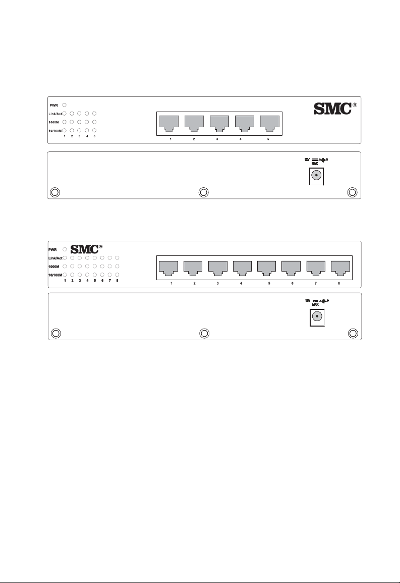
Puertos RJ-45 en el panel frontal
Los modelos EZ Switch 10/100 disponen de 5/8 puertos 1000BASE-T con
conectores RJ-45 ubicados en el panel frontal del switch. Dado que todos
los puertos admiten el funcionamiento MDI/MDI-X automático, puede
utilizar cables directos para todas las conexiones de red de los PC
o servidores, o bien de otros switches o hubs.
Indicadores LED en el panel frontal
El panel frontal del switch dispone de indicadores LED de estado para
controlar el sistema a simple vista. En la tabla que sigue se detallan las
funciones de los diversos indicadores:
LED de estado del sistema y de los puertos
LED Condición Estado
Alimentación Encendido El switch recibe corriente.
Apagado El switch no recibe corriente.
Puertos
Link/Act Encendido El puerto ha establecido una conexión
de red válida.
Apagado El puerto no ha establecido una conexión
de red.
Intermitente Tráfico pasando por el puerto.
1000M Encendido Indica que el puerto funciona a 1000 Mbps.
Apagado Indica que el puerto no funciona
10/100M Encendido Indica que el puerto funciona a 100 Mbps.
Apagado Indica que el puerto funciona a 10 Mbps.
a 1000 Mbps.
2
SMC8505T
EZSwitch 10/100/1000
8505T
EZSwitch 10/100/1000
8508T
ANEL TRASERO
P
EZSwitch 10/100/1000
SMC8508T
EZSwitch 10/100/1000
8508T
Panel trasero
La toma de alimentación CC se encuentra en la parte trasera del switch.
8505T
1A
1.25A
3

I
NSTALACIÓN DEL SWITCH
Antes de instalar el switch, compruebe si tiene todos los componentes
mencionados en el apartado “Contenido del paquete”. Recuerde que
puede instalar el switch en cualquier superficie adecuada, siempre
que sea amplia y plana, o bien en un rack estándar EIA de 48,26 cm.
Contenido del paquete
El EZ Switch 10/100/1000 incluye:
• EZ Switch 10/100/1000 (SMC8505T o SMC8508T).
• Cuatro puntos adhesivos de goma.
• Kit de fijación para montaje en rack.
• Adaptador de alimentación CC adecuado.
Selección del emplazamiento
Siga estas recomendaciones para elegir el emplazamiento de la instalación:
• Seleccione una ubicación idónea para el switch:
• Debe ser accesible para la instalación, el cableado y el
mantenimiento del dispositivo.
• La temperatura y la humedad deben estar dentro de los
intervalos indicados en las especificaciones.
• Los LED de estado deben ser fácilmente visibles.
• Debe haber espacio suficiente (aproximadamente cinco
centímetros) en ambos lados para una correcta circulación
del aire.
5

NSTALACIÓN DEL SWITCH
I
• Asegúrese de que el cable de par trenzado siempre está alejado de las
líneas de alimentación, los dispositivos de iluminación fluorescente y
otras fuentes de interferencia eléctrica como radios, transmisores, etc.
• Asegúrese de que dispone de una toma de alimentación de tierra
a 2,44 metros como máximo del switch y que está alimentada a partir
de un cortacircuitos independiente. Al igual que cualquier otro
equipo, se recomienda el uso de un filtro o supresor de sobretensión.
Instrucciones
1. Posición del switch: Tanto si lo monta sobre un escritorio como
en un rack, pegue los cuatro puntos adhesivos en la base del switch.
En el caso del rack, instálelo en un rack EIA estándar EIA de 48,26 cm
utilizando las piezas de fijación incluidas.
2. Alimentación eléctrica: Conecte un extremo del adaptador de
alimentación en el panel trasero del switch y el otro extremo en
un enchufe eléctrico adecuado. Verifique el LED de alimentación
para asegurarse de que el equipo recibe alimentación.
Nota: No hace falta apagar el switch antes de conectar o desconectar
los cables UTP, puesto que estas acciones no interrumpirán el
funcionamiento de otros dispositivos conectados al switch.
3. Conexión de PC: Conecte cada PC a un puerto RJ-45 del switch
utilizando un cable de par trenzado (UTP o STP), blindado o no,
de las categorías 5, 5e o 6, y con una longitud máxima de 100 metros.
El EZ Switch 10/100/1000 admite un máximo de 5/8 PC. Todos
los puertos del switch permiten el funcionamiento MDI/MDI-X
automático, por lo que puede utilizar cables directos para todas las
conexiones de red de los PC o servidores, o bien de otros switches
o hubs.
Nota: Si un dispositivo conectado no admite la negociación
automática, la velocidad de datos se detectará automáticamente
y el modo de comunicación predeterminado será unidireccional.
6

NSTRUCCIONES
I
4. Conmutadores en cascada y otros dispositivos de red:
Todos los puertos del switch admiten la configuración MIDI/MDI-X
automática para las conexiones de cables. Esto le permite utilizar
cable directo para conectarse con otros switches o hubs desde
cualquier puerto del switch. No son necesarios cables de cruce ni
otra configuración de dispositivos. Consulte “Especificaciones de los
cables” en la página 11 en esta guía para obtener más información.
Precaución: No enchufe conectores telefónicos en los puertos RJ-45.
Podría averiar el switch. Use solamente cables de par
trenzado con conectores RJ-45 que se adecuen a las
normativas FCC.
7

NSTALACIÓN DEL SWITCH
E
Z
S
w
i
t
c
h
10
/
10
0
/
10
0
0
8
50
8T
I
Ejemplo de aplicación
A continuación figura una aplicación típica del SMC8505T/SMC8508T.
EZ Switch 10/100/1000
Servidor
SMC-EZ109DT
Estaciones de trabajo
Estaciones de trabajo
con tarjetas PCI Gigabit
SMC9452TX
SMC8508T
0
0
0
1
/
0
0
1
/
0
1
h
itc
w
S
Z
E
8T
0
85
Portátil
Router de banda ancha
inalámbrico SMC2804WBR
Portátil con tarjeta
PC Card inalámbrica
SMC2835W
Internet
3
2
ink
L
1
N
A
L
ty
i
v
i
ct
A
N
A
W
N
A
L
W
R
PW
8

P
ROBLEMAS Y SOLUCIONES
Diagnóstico de los indicadores del switch
1. Síntoma
El LED de alimentación no se ilumina tras el encendido.
Causas posibles
• El adaptador de alimentación CC es defectuoso.
Soluciones posibles
• Compruebe que todo esté conectado.
• Compruebe la toma de alimentación con otro dispositivo.
• Sustituya el adaptador de alimentación CC.
2. Síntoma
El LED de enlace no se ilumina después de realizar la conexión.
Causas posibles
• El puerto del switch, la tarjeta de red o el cable son defectuosos.
Soluciones posibles
• Compruebe que el switch y el dispositivo conectado estén encendidos.
• Asegúrese de que el cable de red esté conectado a ambos dispositivos.
• Verifique que está utilizando un cable de la categoría 5 o superior
para las conexiones de 10/100 Mbps, uno de la categoría 5, 5e o 6
para las conexiones de 1000 Mbps, y que la longitud de los cables
no supera los 100 metros.
• Compruebe si la tarjeta de red y las conexiones de cable tienen
defectos.
• Sustituya la tarjeta o el cable defectuosos.
9
C
Especificaciones de los cables
Especificaciones y tipos de cables
Cable Tipo Extensión
10BASE-T Cableado Cat. 3 o superior,
100 ohmios UTP
100BASE-TX Cableado Cat. 3 o superior,
100 ohmios UTP
1000BASE-T Cableado Cat. 3, 5e o 6,
100 ohmios UTP
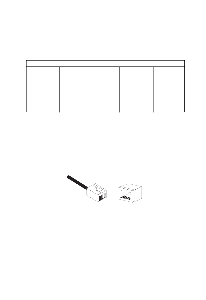
Asignaciones de terminales 10BASE-T/ 100BASE-TX
Precaución: NO enchufe conectores telefónicos en los puertos RJ-45.
Use solamente cables de par trenzado con conectores RJ-45
que se adecuen a las normativas FCC.
máx.
100 m RJ-45
100 m RJ-45
100 m RJ-45
ABLES
Conector
8
1
Use cables de par trenzado, blindados (STP) o no (UTP), para las
conexiones RJ-45: un cable de 100 ohmios de la categoría 3 o superior
para las conexiones de 10 Mbps o un cable de 100 ohmios de la
categoría 5 o superior para las conexiones de 100 Mbps. Asegúrese
también de
supere los 100 metros.
que la longitud de cualquier conexión de par trenzado no
8
1
11

ABLES
C
Dado que todos los puertos de este switch admiten el funcionamiento
MDI/MDI-X automático, puede utilizar cables directos para todas las
conexiones de red de los PC o servidores, o bien de otros switches o
hubs. En los cables directos, los terminales 1, 2, 3 y 6 de un extremo
del cable se conectan directamente con los terminales 1, 2, 3 y 6 del
otro extremo.
La siguiente tabla muestra los terminales del puerto MDI
y 10BASE-T/100BASE-TX MDI-X.
Terminal Nombre de la señal MDI-X Nombre de la señal MDI
1 Recibir datos más (RD+) Transmitir datos más (TD+)
2 Recibir datos menos (RD-) Transmitir datos menos (TD-)
3 Transmitir datos más (TD+) Recibir datos más (RD+)
6 Transmitir datos menos (TD-) Recibir datos menos (RD-)
4,5,7,8 No se utiliza a 10/100 Mbps No se utiliza a 10/100 Mbps
Asignaciones de terminales 1000BASE-T
La siguiente tabla muestra los terminales del puerto MDI-X y
100BASE-T MDI. Estos puertos necesitan que estén conectados
los cuatro pares de cables. Recuerde que para el funcionamiento
de 1000BASE-T, los cuatros pares se utilizan tanto para transmitir
como para recibir.
Use un cable de par trenzado de 100 ohmios, blindado (STP) o no (UTP),
de la categoría 5, 5e o 6 para las conexiones de 1000BASE-T. Asegúrese
también de que la longitud de cualquier conexión de par trenzado no
supere los 100 metros.
12

EQUISITOS DE LOS CABLES PARA
R
1000BASE- T
Terminal MDI MDI-X
1
2
3
4
5
6
7
8
Datos bidireccionales uno más
(BI_D1+)
Datos bidireccionales uno menos
(BI_D1-)
Datos bidireccionales dos más
(BI_D2+)
Datos bidireccionales tres más
(BI_D3+)
Datos bidireccionales tres menos
(BI_D3-)
Datos bidireccionales dos menos
(BI_D2-)
Datos bidireccionales cuatro más
(BI_D4+)
Datos bidireccionales cuatro menos
(BI_D4-)
Datos bidireccionales dos más
(BI_D2+)
Datos bidireccionales dos
menos (BI_D2-)
Datos bidireccionales uno más
(BI_D1+)
Datos bidireccionales cuatro
más (BI_D4+)
Datos bidireccionales cuatro
menos (BI_D4-)
Datos bidireccionales uno
menos (
BI_D1-)
Datos bidireccionales tres más
(BI_D3+)
Datos bidireccionales tres menos
(BI_D3-)
Requisitos de los cables para 1000BASE-T
Todos los cables UTP de la categoría 5 que se utilizan para las conexiones
de 100BASE-TX también deben servir para 1000BASE-T, siempre y
cuando estén conectados los cuatros pares de cables. No obstante, para
las conexiones importantes o para la instalación de cualquier cable
nuevo, se recomienda el empleo de cables de la categoría 5e (categoría 5
mejorada) o 6. Las especificaciones de la categoría 5e y 6 incluyen
parámetros de prueba que sólo son simples recomendaciones en el caso de
la categoría 5. Por consiguiente, el primer paso al preparar los cables de la
categoría 5 para su funcionamiento con 1000BASE-T consiste en realizar
una simple prueba de la instalación del cable que garantice su
compatibilidad con los estándares IEEE 802.3ab.
13

ABLES
C
Prueba para el cable de la categoría 5 existente
El cable instalado de la categoría 5 debe superar pruebas de atenuación,
paradiafonía (Near-End Crosstalk, NEXT) y telediafonía (Far-End
Crosstalk, FEXT). La información de estas pruebas está especificada
en el estándar ANSI/TIA/EIA-TSB-67. Adicionalmente, los cables también
deben superar los parámetros de prueba de pérdida de retorno
y telediafonía de igual nivel (Equal-Level Far-End Crosstalk, ELFEXT).
Estas pruebas figuran en el boletín ANSI/TIA/EIA-TSB-95, bajo el
apartado “The Additional Transmission Performance Guidelines for
100 Ohm 4-Pair Category 5 Cabling” (“Directrices para incrementar el
rendimiento de la transmisión con cuatro pares de cables de 100 ohmios
de la categoría 5”).
Al comprobar la instalación de los cables, asegúrese de incluir todos los
cables flexibles entre los switches y los dispositivos finales.
Ajuste del cable de la categoría 5 existente
Si su actual instalación de la categoría 5 no cumple alguno de los
parámetros de prueba para 1000BASE-T, existen básicamente tres
medidas que pueden adoptarse para intentar solventar este problema:
1. Sustituya todos los cables flexibles de la categoría 5 por cables
de alto rendimiento de la categoría 5e o 6.
2. Reduzca el número de conectores empleados en el enlace.
3. Vuelva a conectar algunos conectores del enlace.
14

P
RODUCT
S
PECIFICATIONS
EZ Switch 10/100/1000
Standards Conformance
IEEE 802.3
IEEE 802.3u
IEEE 802.3x
IEEE 802.3ab
Communication Rate
10, 100, and 1000 Mbps
Communication Mode
Full or half duplex at 10/100 Mbps
Full duplex at 1000 Mbps
Media Supported
10BASE-T: 100-ohm Category 3 or better twisted-pair
100BASE-TX: 100-ohm Category 5 or better twisted pair
1000BASE-T: 100-ohm Category 5, 5e, or 6 twisted-pair
Number of Ports
SMC8505T: 5 RJ-45 1000BASE-T ports
SMC8508T: 8 RJ-45 1000BASE-T ports
Indicator Panel
Power
Ports: Link/Act, 1000M, 10/100M
Dimensions
19.64 x 11.65 x 3.66 cm, (7.76 x 4.6 x 1.44 in)
Wei gh t
SMC8505T: 0.59 kg (1.309 lbs)
SMC8508T: 0.62 kg (1.378 lbs)
MAC Address Table
8 K entries
15

RODUCT SPECIFICATIONS
P
Memory Buffer
768 Kbits per unit
Power Consumption
SMC8505T: 12 Watts
SMC8508T: 15 Watts
Power Requirement
DC input
SMC8505T: 12 V, 1 A
SMC8508T: 12 V, 1.25 A
Tem pe ratu re
Operating: 0 ~ 40 ºC / 32 ~ 98 ºF
Storage: -40 ~ 70 ºC / -40 ~ 158 ºF
Humidity
10% to 90% non-condensing
EMC/Safety Compliances
CE Mark
Immunity
EN 61000-4-2/3/4/5/6/8/11
Emissions
FCC Class B, CISPR Class B, EN 61000-3-2/3
Safety
CSA (UL1950, CSA 22.2.950), TUV/GS (EN60950)
16

C
OMPLIANCES
FCC - Class B
This equipment has been tested and found to comply with the limits for a Class B digital device,
pursuant to Part 15 of the FCC Rules. These limits are designed to provide reasonable protection
against harmful interference in a residential installation. This equipment generates, uses and can
radiate radio frequency energy and, if not installed and used in accordance with instructions,
may cause harmful interference to radio communications. However, there is no guarantee that
the interference will not occur in a particular installation. If this equipment does cause harmful
interference to radio or television reception, which can be determined by turning the equipment
off and on, the user is encouraged to try to correct the interference by one or more of the following measures:
• Reorient the receiving antenna
• Increase the separation between the equipment and receiver
• Connect the equipment into an outlet on a circuit different from that to which the receiver is
connected
• Consult the dealer or an experienced radio/TV technician for help
EC Conformance Declaration - Class B
SMC contact for these products in Europe is:
SMC Networks Europe,
Edificio Conata II,
Calle Fructuós Gelabert 6-8, 2
08970 - Sant Joan Despí,
Barcelona, Spain.
This information technology equipment complies with the requirements of the Council
Directive 89/336/EEC on the Approximation of the laws of the Member States relating to
Electromagnetic Compatibility and 73/23/EEC for electrical equipment used within certain
voltage limits and the Amendment Directive 93/68/EEC. For the evaluation of the
compliance with these Directives, the following standards were applied:
RFI Emission: • Limit class B according to EN 55022:1998, IEC 60601-1-2 (EMC,
medical)
• Limit class A for harmonic current emission according to
EN 61000-3-2/1995
• Limitation of voltage fluctuation and flicker in low-voltage supply
system according to EN 61000-3-3/1995
Immunity: • Product family standard according to EN 55024:1998
• Electrostatic Discharge according to EN 61000-4-2:1995
(Contact Discharge: ±4 kV, Air Discharge: ±8 kV)
o
, 4a,
i

OMPLIANCES
C
• Radio-frequency electromagnetic field according to EN 61000-4-3:1996
(80 - 1000 MHz with 1 kHz AM 80% Modulation: 3 V/m)
• Electrical fast transient/burst according to EN 61000-4-4:1995 (AC/DC
power supply: ±1 kV, Data/Signal lines: ±0.5 kV)
• Surge immunity test according to EN 61000-4-5:1995
(AC/DC Line to Line: ±1 kV, AC/DC Line to Earth: ±2 kV)
• Immunity to conducted disturbances, Induced by radio-frequency
fields: EN 61000-4-6:1996 (0.15 - 80 MHz with
1 kHz AM 80% Modulation: 3 V/m)
• Power frequency magnetic field immunity test according to
EN 61000-4-8:1993 (1 A/m at frequency 50 Hz)
• Voltage dips, short interruptions and voltage variations immunity test
according to EN 61000-4-11:1994 (>95% Reduction @10 ms, 30%
Reduction @500 ms, >95% Reduction @5000 ms)
LV D:
MDD:
• EN 60950 (A1/1992; A2/1993; A3/1993; A4/1995; A11/1997)
• IEC 60601-1
Industry Canada - Class B
This digital apparatus does not exceed the Class B limits for radio noise emissions from digital
apparatus as set out in the interference-causing equipment standard entitled “Digital Apparatus”
ICES-003 of the Department of Communications.
Cet appareil numérique respecte les limites de bruits radioélectriques applicables aux appareils
numériques de Classe B prescrites dans la norme sur le matériel brouilleur: « Appareils
Numériques » NMB-003 édictée par le ministère des Communications.
Safety Compliance
CSA/NRTL (C22.2.950, UL 1950)
EN60950, (IEC 950)
ii

OMPLIANCES
C
Wichtige Sicherheitshinweise (Germany)
1. Bitte lesen Sie diese Hinweise sorgfältig durch.
2. Heben Sie diese Anleitung für den späteren Gebrauch auf.
3. Vor jedem Reinigen ist das Gerät vom Stromnetz zu trennen. Verwenden Sie keine Flüssigoder
Aerosolreiniger. Am besten eignet sich ein angefeuchtetes Tuch zur Reinigung.
4. Die Netzanschlu ßsteckdose soll nahe dem Gerät angebracht und leicht zugänglich sein.
5. Das Gerät ist vor Feuchtigkeit zu schützen.
6. Bei der Aufstellung des Gerätes ist auf sicheren Stand zu achten. Ein Kippen oder Fallen
könnte Beschädigungen hervorrufen.
7. Die Belüftungsöffnungen dienen der Luftzirkulation, die das Gerät vor Überhitzung schützt.
Sorgen Sie dafür, daß diese Öffnungen nicht abgedeckt werden.
8. Beachten Sie beim Anschluß an das Stromnetz die Anschlußwerte.
9. Verlegen Sie die Netzanschlußleitung so, daß niemand darüber fallen kann. Es sollte auch
nichts auf der Leitung abgestellt werden.
10. Alle Hinweise und Warnungen, die sich am Gerät befinden, sind zu beachten.
11. Wird das Gerät über einen längeren Zeitraum nicht benutzt, sollten Sie es vom Stromnetz
trennen. Somit wird im Falle einer Überspannung eine Beschädigung vermieden.
12. Durch die Lüftungsöffnungen dürfen niemals Gegenstände oder Flüssigkeiten in das Gerät
gelangen. Dies könnte einen Brand bzw. elektrischen Schlag auslösen.
13. Öffnen sie niemals das Gerät. Das Gerät darf aus Gründen der elektrischen Sicherheit nur
von authorisiertem Servicepersonal geöffnet werden.
14. Wenn folgende Situationen auftreten ist das Gerät vom Stromnetz zu trennen und von einer
qualifizierten Servicestelle zu überprüfen:
a. Netzkabel oder Netzstecker sind beschädigt.
b. Flüssigkeit ist in das Gerät eingedrungen.
c. Das Gerät war Feuchtigkeit ausgesetzt.
d. Wenn das Gerät nicht der Bedienungsanleitung entsprechend funktioniert oder Sie mit
Hilfe dieser Anleitung keine Verbesserung erzielen.
e. Das Gerät ist gefallen und/oder das Gehäuse ist beschädigt.
f. Wenn das Gerät deutliche Anzeichen eines Defektes aufweist.
15. Stellen Sie sicher, daß die Stromversorgung dieses Gerätes nach der EN 60950 geprüft ist.
Ausgangswerte der Stromversorgung sollten die Werte von AC 7.5-8 V, 50-60 Hz nicht über
oder unterschreiten sowie den minimalen Strom von 1 A nicht unterschreiten.
Der arbeitsplatzbezogene Schalldruckpegel nach DIN 45 635 Teil 1000 beträgt 70dB(A)
oder weniger.
iii

L
EGAL INFORMATION
AND
C
ONTACTS
SMC's Limited Warranty Statement
SMC Networks Europe ("SMC") warrants its products to be free from defects in
workmanship and materials, under normal use and service, for the applicable warranty
term. All SMC products carry a standard 2 year limited warranty from the date of purchase
from SMC or its Authorized Reseller. SMC may, at its own discretion, repair or replace any
product not operating as warranted with a similar or functionally equivalent product,
during the applicable warranty term. SMC will endeavour to repair or replace any product
returned under warranty within 30 days of receipt of the product. As new technologies
emerge, older technologies become obsolete and SMC will, at its discretion, replace an older
product in its product line with one that incorporates these newer technologies
The standard limited warranty can be upgraded to a 5 year Limited Lifetime * warranty by
registering new products within 30 days of purchase from SMC or its Authorized Reseller.
Registration can be accomplished via the enclosed product registration card or online via
the SMC web site. Failure to register will not affect the standard limited warranty. The
Limited Lifetime warranty covers a product during the Life of that Product, which is
defined as a period of 5 years from the date of purchase of the product from SMC or its
authorized reseller.
All products that are replaced become the property of SMC. Replacement products may be
either new or reconditioned. Any replaced or repaired product carries, either a 30-day
limited warranty or the remainder of the initial warranty, whichever is longer. SMC is not
responsible for any custom software or firmware, configuration information, or memory
data of Customer contained in, stored on, or integrated with any products returned to SMC
pursuant to any warranty. Products returned to SMC should have any customer-installed
accessory or add-on components, such as expansion modules, removed prior to returning
the product for replacement. SMC is not responsible for these items if they are returned
with the product.
Customers must contact SMC for a Return Material Authorization number prior to
returning any product to SMC. Proof of purchase may be required. Any product returned
to SMC without a valid Return Material Authorization (RMA) number clearly marked on
the outside of the package will be returned to customer at customer's expense. Customers
are responsible for all shipping charges from their facility to SMC. SMC is responsible for
return shipping charges from SMC to customer.
WARRANTIES EXCLUSIVE: IF A SMC PRODUCT DOES NOT OPERATE AS
WARRANTED ABOVE, CUSTOMER'S SOLE REMEDY SHALL BE REPAIR OR
REPLACEMENT OF THE PRODUCT IN QUESTION, AT SMC'S OPTION. THE
FOREGOING WARRANTIES AND REMEDIES ARE EXCLUSIVE AND ARE IN LIEU
v

EGAL INFORMATION AND CONTACTS
L
OF ALL OTHER WARRANTIES OR CONDITIONS, EXPRESSED OR IMPLIED,
EITHER IN FACT OR BY OPERATION OF LAW, STATUTORY
OR OTHERWISE, INCLUDING WARRANTIES OR CONDITIONS OF
MERCHANTABILITY AND FITNESS FOR A PARTICULAR PURPOSE. SMC NEITHER
ASSUMES NOR AUTHORIZES ANY OTHER PERSON TO ASSUME FOR IT ANY
OTHER LIABILITY IN CONNECTION WITH THE SALE, INSTALLATION,
MAINTENANCE OR USE OF ITS PRODUCTS. SMC SHALL NOT BE LIABLE UNDER
THIS WARRANTY IF ITS TESTING AND EXAMINATION DISCLOSE THE ALLEGED
DEFECT IN THE PRODUCT DOES NOT EXIST OR WAS CAUSED BY CUSTOMER'S
OR ANY THIRD PERSON'S MISUSE, NEGLECT, IMPROPER INSTALLATION OR
TESTING, UNAUTHORIZED ATTEMPTS TO REPAIR, OR ANY OTHER CAUSE
BEYOND THE RANGE OF THE INTENDED USE, OR BY ACCIDENT, FIRE,
LIGHTNING, OR OTHER HAZARD.
LIMITATION OF LIABILITY: IN NO EVENT, WHETHER BASED IN
CONTRACT OR TORT (INCLUDING NEGLIGENCE), SHALL SMC BE LIABLE FOR
INCIDENTAL, CONSEQUENTIAL, INDIRECT, SPECIAL, OR PUNITIVE DAMAGES
OF ANY KIND, OR FOR LOSS OF REVENUE, LOSS OF BUSINESS,
OR OTHER FINANCIAL LOSS ARISING OUT OF OR IN CONNECTION WITH THE
SALE, INSTALLATION, MAINTENANCE, USE, PERFORMANCE, FAILURE, OR
INTERRUPTION OF ITS PRODUCTS, EVEN IF SMC OR ITS AUTHORIZED
RESELLER HAS BEEN ADVISED OF THE POSSIBILITY OF SUCH DAMAGES.
SOME COUNTRIES DO NOT ALLOW THE EXCLUSION OF IMPLIED
WARRANTIES OR THE LIMITATION OF INCIDENTAL OR CONSEQUENTIAL
DAMAGES FOR CONSUMER PRODUCTS, SO THE ABOVE LIMITATIONS AND
EXCLUSIONS MAY NOT APPLY TO YOU. THIS WARRANTY GIVES YOU SPECIFIC
LEGAL RIGHTS, WHICH MAY VARY FROM COUNTRY TO COUNTRY. NOTHING
IN THIS WARRANTY SHALL BE TAKEN TO AFFECT YOUR STATUTORY RIGHTS.
* Under the limited lifetime warranty, internal and external power supplies,
fans and cables are covered by a standard one-year warranty from date of purchase.
Full Installation Manual
Full installation manuals are provided on the Installation CD-Rom. Manuals in other
languages than those included on the CD-Rom are provided on www.smc-europe.com
(section support).
Firmware and Drivers
For latest driver, technical information and bug-fixes please visit www.smc-europe.com
(section support).
vi

EGAL INFORMATION AND CONTACTS
L
Contact SMC
Contact details for your relevant countries are available on www.smc-europe.com and
www.smc.com
.
Statement of Conditions
In line with our continued efforts to improve internal design, operational function, and/or
reliability, SMC reserves the right to make changes to the product(s) described in this
document without notice. SMC does not assume any liability that may occur due to the
use or application of the product(s) described herein. In order to obtain the most accurate
knowledge of installation, bug-fixes and other product related information we advise to visit
the relevant product support page at www.smc-europe.com
equipment. All information is subject to change without notice.
before you start installing the
Limitation of Liability
In no event, whether based in contract or tort (including negligence), shall SMC be liable
for incidental, consequential, indirect, special or punitive damages of any kind, or for loss
of revenue, loss of business or other financial loss arising out of or in connection with the
sale, installation, maintenance, use, performance, failure or interruption of its products,
even if SMC or its authorized reseller has been adviced of the possiblity of such damages.
Copyright
Information furnished by SMC Networks, Inc. (SMC) is believed to be accurate and
reliable. However, no responsibility is assumed by SMC for its use, nor for any
infringements of patents or other rights of third parties which may result from its use. No
license is granted by implication or otherwise under any patent or patent rights of SMC.
SMC reserves the right to change specifications at any time without notice.
Trademarks
SMC is a registered trademark and EZ Connect is a trademark of SMC Networks, Inc.
Other product and company names are trademarks or registered trademarks of their
respective holders.
vii

Nº de modelo: SMC8505TX, SMC8508TX V.2
Nº de publicación: 150000005200H R01
 Loading...