

Page 1
Page 2

EZ Switch™ 10/100/1000
Manuale utente
Dalla linea SMC EZ di soluzioni LAN dal costo ridotto
per gruppi di lavoro
Settembre 2003
Numero pubblicazione # 150000005200H R01
Page 3

I
NDICE
Introduzione . . . . . . . . . . . . . . . . . . . . . . . . . . . . . . . . . . 1
Caratteristiche e vantaggi . . . . . . . . . . . . . . . . . . . . . . . . . . . . . . . . . . . . 1
Porte RJ-45 sul pannello frontale . . . . . . . . . . . . . . . . . . . . . . . . . . . . . . 2
LED sul pannello frontale . . . . . . . . . . . . . . . . . . . . . . . . . . . . . . . . . . . . 2
SMC8505T . . . . . . . . . . . . . . . . . . . . . . . . . . . . . . . . . . . . . . . . . . 3
SMC8508T . . . . . . . . . . . . . . . . . . . . . . . . . . . . . . . . . . . . . . . . . . 3
Pannello posteriore . . . . . . . . . . . . . . . . . . . . . . . . . . . . . . . . . . . . . . . . .3
Installazione dello switch . . . . . . . . . . . . . . . . . . . . . . . . 5
Contenuto della confezione . . . . . . . . . . . . . . . . . . . . . . . . . . . . . . . . . . 5
Selezione di un sito . . . . . . . . . . . . . . . . . . . . . . . . . . . . . . . . . . . . . . . . . 5
Istruzioni . . . . . . . . . . . . . . . . . . . . . . . . . . . . . . . . . . . . . . . . . . . . . . . . . 6
Risoluzione dei problemi . . . . . . . . . . . . . . . . . . . . . . . . 9
Diagnosi degli indicatori dello switch . . . . . . . . . . . . . . . . . . . . . . . . . . . 9
Cavi . . . . . . . . . . . . . . . . . . . . . . . . . . . . . . . . . . . . . . . . 11
Specifiche dei cavi . . . . . . . . . . . . . . . . . . . . . . . . . . . . . . . . . . . . . . . . . 11
Assegnazione dei pin per collegamenti 10BASE-T/100BASE-TX . . . . .11
Assegnazione dei pin per collegamenti 1000BASE-T . . . . . . . . . . . . . . . 12
Requisiti dei cavi per collegamenti 1000BASE-T . . . . . . . . . . . . . . . . . . 13
Test dei cavi per i cavi Categoria 5 esistenti . . . . . . . . . . . . . . . . 14
Taratura del cablaggio Categoria 5 esistente . . . . . . . . . . . . . . . . 14
Product Specifications . . . . . . . . . . . . . . . . . . . . . . . . . 15
EZ Switch 10/100/1000 . . . . . . . . . . . . . . . . . . . . . . . . . . . . . . . . . . . . . 15
EMC/Safety Compliances . . . . . . . . . . . . . . . . . . . . . . . . . . . . . 16
Compliances . . . . . . . . . . . . . . . . . . . . . . . . . . . . . . . . . . .i
Legal Information and Contacts . . . . . . . . . . . . . . . . . . v
i
Page 4

I
NTRODUZIONE
EZ Switch 10/100/1000, SMC8505T e SMC8508T sono switch
Gigabit a elevate prestazioni progettati per fornire la connettività Gigabit
per il desktop. Essi forniscono 5/8 porte 1000BASE-T full-duplex
migliorano significativamente le prestazioni di rete e incrementano il
throughput per applicazioni ad elevata larghezza di banda. Grazie ai
10/16 Gigabit di larghezza di banda aggregata questi switch forniscono
la soluzione più efficace per soddisfare la crescente domanda relativa
alle risorse di rete limitate.
Caratteristiche e vantaggi
• Negoziazione automatica supportata da tutte le porte.
• Operazione MDI/MDI-X automatica.
• La conformità IEEE 802.3ab, 802.3u e 802.3 garantisce la
compatibilità con gli hub, gli switch e le schede standard
di qualsiasi produttore.
• La commutazione Store-and-forward (archivia e inoltra) garantisce
una trasmissione priva di errori.
• Il controllo di flusso half duplex e full duplex evita che i pacchetti
siano eliminati in caso di caricamento eccessivo.
• Plug-and-Play, configurazione non necessaria.
•LED “a colpo d'occhio” per il monitoraggio delle porte e dello
stato del sistema.
• Montaggio su scrivania o in rack.
Ethernet
che
1
Page 5

NTRODUZIONE
I
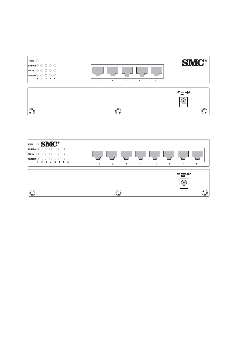
Porte RJ-45 sul pannello frontale
I modelli EZ Switch 10/100 possiedono 5/8 porte 1000BASE-T con
connettori RJ-45 collocati sul pannello frontale dello switch. Grazie al
supporto automatico dell'operazione MDI/MDI-X per tutte le porte,
è possibile usare i cavi diretti per tutte le connessioni di rete a PC,
server o ad altri switch o hub.
LED sul pannello frontale
Il pannello frontale dello switch possiede LED di stato per monitorare il
sistema con un “colpo d'occhio”. La tabella seguente illustra in dettaglio
le funzioni dei vari indicatori.
LED di stato delle porte e di sistema
LED Condizione Stato
Power
(Alimentazione)
Porte
Link/Act (Coll./
Att)
1000M Acceso Indica che la porta sta funzionando
10/100M Acceso Indica che la porta sta funzionando
Acceso Lo switch è alimentato.
Spento Lo switch non è alimentato.
Acceso La porta ha stabilito un collegamento
di rete valido.
Spento La porta non ha stabilito un
collegamento di rete valido.
Lampeggiante Passaggio di dati attraverso la porta.
a 1000 Mbps.
Spento Indica che la porta non sta funzionando
a 1000 Mbps.
a 100 Mbps.
Spento Indica che la porta sta funzionando
a 10 Mbps.
2
Page 6
SMC8505T
EZSwitch 10/100/1000
8505T
EZSwitch 10/100/1000
8508T
ANNELLO POSTERIORE
P
SMC8508T
EZSwitch 10/100/1000
8508T
Pannello posteriore
La presa dell'alimentazione CC è collocata sul pannello posteriore
dello switch.
EZSwitch 10/100/1000
1A
1.25A
8505T
3
Page 7

I
NSTALLAZIONE DELLO SWITCH
Prima di installare lo switch verificare di disporre di tutti gli elementi
elencati in “Contenuto della confezione”. Si noti che è possibile installare
lo switch solo su una superficie dalla larghezza idonea o in un rack EIA
standard da 19 pollici.
Contenuto della confezione
Lo EZ Switch™ 10/100/1000 include:
• EZ Switch™ 10/100/1000 (SMC8505T o SMC8508T).
• Quattro cuscinetti in gomma.
• Kit di staffe per montaggio in rack.
• Adattatore di alimentazione CC appropriato.
Selezione di un sito
Attenersi alle linee guida sulla selezione del sito descritte di
seguito prima di scegliere una postazione.
• Selezione di una postazione idonea per lo switch:
• Deve essere accessibile per l'installazione, il cablaggio
e la manutenzione.
• La temperatura e l'umidità devono essere comprese
nell'intervallo indicato nelle specifiche.
• Il LED di stato deve essere ben visibile.
• Ci deve essere spazio adeguato (circa 5 cm) su tutti
i lati per consentire una ventilazione appropriata.
5
Page 8

NSTALLAZIONE DELLO SWITCH
I
• Verificare che il cavo di tipo doppino sia sempre posato lontano dalle
linee di alimentazione, dagli impianti d'illuminazione fluorescente
o da altre sorgenti di interferenze elettriche come radio, trasmettitori
ecc.
• Verificare che vi sia una presa di alimentazione con messa a terra
appropriata entro 2,44 m (8 piedi) dallo switch e che sia alimentato
tramite un interruttore automatico indipendente. Come qualsiasi
altra apparecchiatura, è consigliabile l'uso di un filtro o di un
soppressore di transienti.
Istruzioni
1. Collocazione dello switch: per la scrivania o il montaggio
a scaffale, fissare i quattro cuscinetti in gomma adesivi sul fondo
dello switch. Per il montaggio in rack, installarlo in un rack EIA
standard da 19 pollici tramite le staffe in dotazione.
2. Collegamento dell'alimentazione: collegare un'estremità
dell'adattatore di alimentazione alla relativa presa sul pannello
posteriore dello switch e inserire l'altra estremità in una presa
elettrica appropriata. Per assicurarsi che l'alimentazione sia
collegata verificare che il LED relativo sia acceso.
Nota: Non è necessario spegnere lo switch prima di collegare o
scollegare i cavi UTP poiché tali azioni non interrompono
il funzionamento di altre periferiche collegate allo switch.
3. Connessione dei PC: collegare ciascun PC a una porta RJ-45
dello switch tramite un cavo di tipo doppino Categoria 5, 5e o 6
schermato o non schermato (UTP o STP) dalla lunghezza massima
di 100 m. Lo EZ Switch™ 10/100/1000 supporta fino a 5/8 PC.
le porte dello switch supportano l'operazione MDI/MDI-X
automatica, quindi è possibile usare cavi diretti per tutte le
connessioni di rete a PC, server o ad altri switch o hub.
6
Tu tt e
Page 9

STRUZIONI
I
Nota: Se un dispositivo collegato non supporta la negoziazione
automatica, la velocità di trasferimento dei dati viene rilevata
automaticamente e la modalità di comunicazione impostata
su half duplex.
4. Switch in cascata e altri dispositivi di rete: tutte le porte dello
switch supportano la configurazione automatica MDI/MDI-X
per il collegamento dei cavi. Pertanto è possibile utilizzare un cavo
diretto per collegare gli altri switch o hub da qualsiasi porta dello
switch. Non sono necessari cavi di tipo crossover o altre impostazioni
dei dispositivi. Per ulteriori informazioni consultare la sezione
“Specifiche dei cavi” a pagina 11 della presente guida.
Avvertenza: Non collegare prese telefoniche alle porte RJ-45. Lo switch
potrebbe danneggiarsi. Con i connettori RJ-45 utilizzare
solo cavi di tipo doppino conformi agli standard FCC.
7
Page 10
NSTALLAZIONE DELLO SWITCH
E
Z
S
w
i
t
c
h
10
/
10
0
/
10
0
0
8
50
8T
I
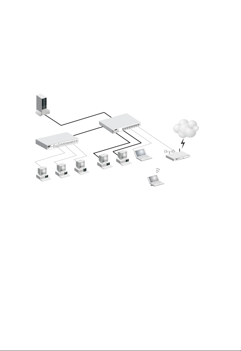
Esempio pratico
Un utilizzo tipico degli switch SMC8505T/SMC8508T è illustrato
di seguito.
EZ Switch 10/100/1000
Server
SMC-EZ109DT
Stazioni di lavoro
Stazioni di lavoro con
schede PCI Gigabit
SMC9452TX
SMC8508T
0
0
0
1
/
0
0
1
/
0
1
h
itc
w
S
Z
E
8T
0
85
Notebook
Notebook con
scheda PC wireless
SMC2835W
Internet
3
2
k
n
i
L
1
N
A
L
y
t
i
v
i
t
c
A
N
A
W
N
A
L
W
R
W
P
Router a banda larga
wireless SMC2804WBR
8
Page 11

R
ISOLUZIONE DEI PROBLEMI
Diagnosi degli indicatori dello switch
1. Sintomo
Il LED di alimentazione non si illumina all'accensione dello switch.
Cause possibili
• L'adattatore di alimentazione CC può essere guasto.
Soluzioni possibili
• Verificare le connessioni lasche.
• Verificare la presa di alimentazione usando un altro dispositivo.
• Sostituire l'adattatore di alimentazione CC.
2. Sintomo
Il LED di collegamento non si accende dopo aver effettuato
la connessione.
Cause possibili
• La porta dello switch, la scheda di rete o il cavo possono essere guasti.
Soluzioni possibili
• Controllare che lo switch e il dispositivo collegato siano entrambi
accesi.
• Assicurarsi che il cavo di rete sia connesso a entrambe le periferiche.
• Verificare che sia stato utilizzato un cavo Categoria 5 o superiore per
una velocità di 10/100 Mbps, Categoria 5, 5e, o 6 per una velocità di
1000 Mbps e che la lunghezza di qualsiasi cavo non superi i 100 m.
• Controllare che non vi siano difetti nelle connessioni della scheda
di rete e del cavo.
• Se necessario sostituire la scheda o il cavo difettosi.
9
Page 12
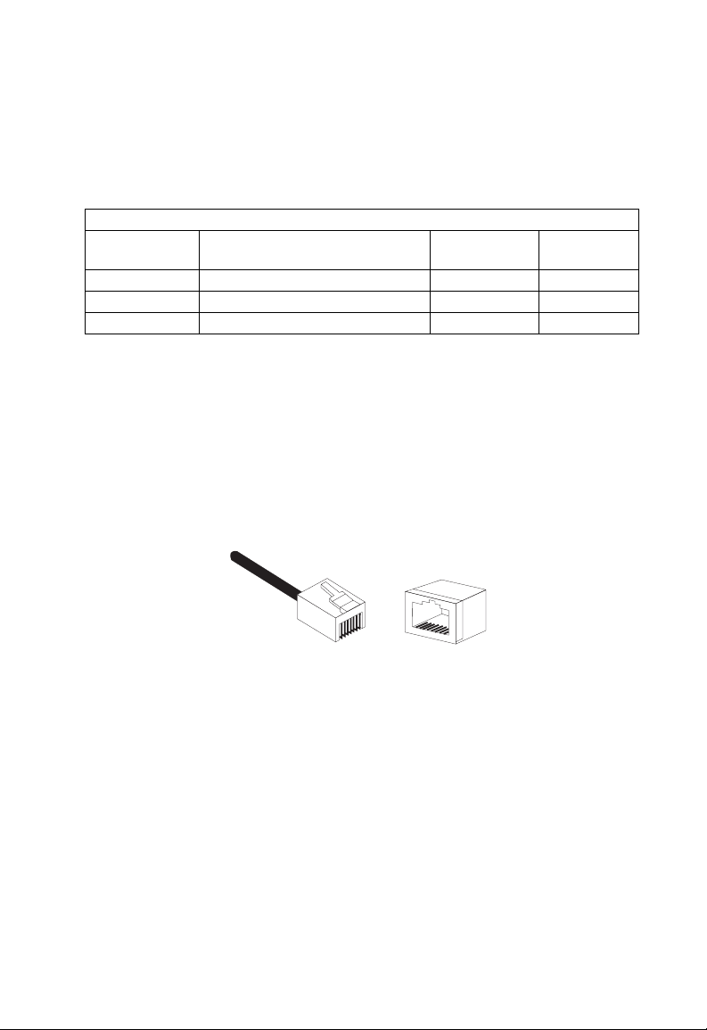
Specifiche dei cavi
Tipi di cavo e specifiche tecniche
Cavo Tipo Lunghezza
max
10BASE-T Cat. 3 o superiore, 100 Ohm UTP 100 m RJ-45
100BASE-TX Cat. 5 o superiore, 100 Ohm UTP 100 m RJ-45
1000BASE-T Cat. 5, 5e o 6, 100 Ohm UTP 100 m RJ-45
Assegnazione dei pin per collegamenti 10BASE-T/100BASE-TX
Avvertenza: NON collegare prese telefoniche alle porte RJ-45.
Con i connettori RJ-45 utilizzare solo cavi di tipo
doppino conformi agli standard FCC.
C
AVI
Connettore
8
1
Usare un cavo di tipo doppino non schermato (UTP) o schermato (STP)
per le connessioni RJ-45: cavo Categoria 3 o superiore da 100 Ohm per
connessioni a 10 Mbps o cavo Categoria 5 o superiore da 100 Ohm per
connessioni a 100 Mbps. Controllare inoltre
tipo doppino non superi i 100 metri (328 piedi).
8
1
che la lunghezza dei cavi di
11
Page 13

AVI
C
Grazie al supporto automatico dell'operazione MDI/MDI-X per tutte le
porte dello switch è possibile usare cavi diretti per tutte le connessioni di
rete a PC, server o ad altri switch o hub. Nei cavi diretti i pin 1, 2, 3 e 6,
di un'estremità del cavo, sono collegati direttamente ai pin 1, 2, 3 e 6
dell'altra estremità del cavo.
La tabella sottostante illustra gli schemi dei contatti per le porte
10BASE-T/100BASE-T X MDI-X e MDI.
Pin Denominazione segnale
MDI-X
1 Ricezione Dati Più (RD+) Trasmissione Dati Più (TD+)
2 Ricezione Dati Meno (RD-) Trasmissione Dati Meno (TD-)
3 Trasmissione Dati Più (TD+) Ricezione Dati Più (RD+)
6 Trasmissione Dati Meno (TD-) Ricezione Dati Meno (RD-)
4,5,7,8 Non usato a 10/100 Mbps Non usato a 10/100 Mbps
Denominazione segnale MDI
Assegnazione dei pin per collegamenti 1000BASE-T
La tabella sottostante illustra gli schemi dei contatti per le porte
1000BASE-T MDI e MDI-X. Queste porte richiedono che siano
collegate tutte e quattro le coppie di cavi. Si noti che per il
funzionamento a 1000BASE-T tutte e quattro le coppie di cavi
sono usate per la trasmissione e la ricezione.
Per le connessioni 1000BASE-T usare un cavo di tipo doppino
Categoria 5, 5e o 6 da 100 Ohm non schermato (UTP) o schermato
(STP). Controllare inoltre che la lunghezza dei cavi di tipo doppino
non superi i 100 metri (328 piedi).
12
Page 14

EQUISITI DEI CAVI PER COLLEGAMENTI
R
1000 BA SE- T
Pin MDI MDI-X
Dati Uno Più (BI_D1+)
1
bidirezionale
Dati Uno Meno (BI_D1-)
2
bidirezionale
Dati Due Più (BI_D2+)
3
bidirezionale
Dati Tre Più (BI_D3+)
4
bidirezionale
Dati Tre Meno (BI_D3-)
5
bidirezionale
Dati Due Meno (BI_D2-)
6
bidirezionale
Dati Quattro Più (BI_D4+)
7
bidirezionale
Dati Quattro Meno (BI_D4-)
8
bidirezionale
Dati Due Più (BI_D2+)
bidirezionale
Dati Due Meno (BI_D2-)
bidirezionale
Dati Uno Più (BI_D1+)
bidirezionale
Dati Quattro Più (BI_D4+)
bidirezionale
Dati Quattro Meno (BI_D4-)
bidirezionale
Dati Uno Meno (
bidirezionale
Dati Tre Più (BI_D3+)
bidirezionale
Dati Tre Meno (BI_D3-)
bidirezionale
BI_D1-)
Requisiti dei cavi per collegamenti 1000BASE-T
Tutti i cavi Categoria 5 UTP usati per i collegamenti 100BASE-TX
dovrebbero anche funzionare per i collegamenti 1000BASE-T, purché
siano connesse tutte e quattro le coppie di fili. Tuttavia, per tutte le
connessioni critiche o le nuove pose dei cavi, si consiglia di usare cavi
Categoria 5e (Categoria 5 avanzata) o 6. Le specifiche della Categoria
5e e 6 includono i parametri dei test che sono solo consigliati per la
Categoria 5. Pertanto la prima fase di preparazione per i cablaggi
Categoria 5 esistenti per collegamenti 1000BASE-T consiste in un
semplice test della posa dei cavi per verificare la conformità allo
standard IEEE 802.3ab.
13
Page 15

AVI
C
Test dei cavi per i cavi Categoria 5 esistenti
I cablaggi Categoria 5 esistenti devono superare i test di attenuazione,
paradiafonia (NEXT, Near-End Crosstalk) e telediafonia (FEXT,
Far-End Crosstalk). Le informazioni sull'esecuzione dei test dei cavi
sono specificate nello standard ANSI/TIA/EIA-TSB-67. Inoltre i cavi
devono anche superare i parametri dei test di telediafonia per attenuazione
di riflessione e livello di equalizzazione (ELFEXT, Return Loss and
Equal-Level Far-End Crosstalk). Questi test sono specificati nel bollettino
ANSI/TIA/EIA-TSB-95, “The Additional Transmission Performance
Guidelines for 100 Ohm 4-Pair Category 5 Cabling” (Addendum linee
guida relative alle prestazioni di trasmissione per cablaggi Categoria 5,
a 4 coppie, da 100 Ohm).
Si noti che, durante il test della posa dei cavi, è necessario comprendere
tutti i cavi dei collegamenti tra gli switch e i dispositivi terminali.
Taratura del cablaggio Categoria 5 esistente
Se la posa dei cavi Categoria 5 esistente non soddisfa uno dei parametri
dei test per il collegamento 1000BASE-T vi sono tre misure fondamentali
che è possibile applicare per provare a risolvere il problema:
1. Sostituire tutti i cavi di collegamento Categoria 5 con cavi
ad alte prestazioni Categoria 5e o 6.
2. Ridurre il numero di connettori usati nel collegamento.
3. Ricollegare qualcuno dei connettori del collegamento.
14
Page 16

P
RODUCT
S
PECIFICATIONS
EZ Switch 10/100/1000
Standards Conformance
IEEE 802.3
IEEE 802.3u
IEEE 802.3x
IEEE 802.3ab
Communication Rate
10, 100, and 1000 Mbps
Communication Mode
Full or half duplex at 10/100 Mbps
Full duplex at 1000 Mbps
Media Supported
10BASE-T: 100-ohm Category 3 or better twisted-pair
100BASE-TX: 100-ohm Category 5 or better twisted pair
1000BASE-T: 100-ohm Category 5, 5e, or 6 twisted-pair
Number of Ports
SMC8505T: 5 RJ-45 1000BASE-T ports
SMC8508T: 8 RJ-45 1000BASE-T ports
Indicator Panel
Power
Ports: Link/Act, 1000M, 10/100M
Dimensions
19.64 x 11.65 x 3.66 cm, (7.76 x 4.6 x 1.44 in)
15
Page 17

RODUCT SPECIFICATIONS
P
Wei ght
SMC8505T: 0.59 kg (1.309 lbs)
SMC8508T: 0.62 kg (1.378 lbs)
MAC Address Table
8 K entries
Memory Buffer
768 Kbits per unit
Power Consumpt ion
SMC8505T: 12 Watts
SMC8508T: 15 Watts
Power Requirement
DC input
SMC8505T: 12 V, 1 A
SMC8508T: 12 V, 1.25 A
Tem pe ra tu re
Operating: 0 ~ 40 ºC / 32 ~ 98 ºF
Storage: -40 ~ 70 ºC / -40 ~ 158 ºF
Humidity
10% to 90% non-condensing
EMC/Safety Compliances
CE Mark
Immunity
EN 61000-4-2/3/4/5/6/8/11
Emissions
FCC Class B, CISPR Class B, EN 61000-3-2/3
Safety
CSA (UL1950, CSA 22.2.950), TUV/GS (EN60950)
16
Page 18

C
OMPLIANCES
FCC - Class B
This equipment has been tested and found to comply with the limits for a Class B digital device,
pursuant to Part 15 of the FCC Rules. These limits are designed to provide reasonable protection
against harmful interference in a residential installation. This equipment generates, uses and can
radiate radio frequency energy and, if not installed and used in accordance with instructions,
may cause harmful interference to radio communications. However, there is no guarantee that
the interference will not occur in a particular installation. If this equipment does cause harmful
interference to radio or television reception, which can be determined by turning the equipment
off and on, the user is encouraged to try to correct the interference by one or more of the following measures:
• Reorient the receiving antenna
• Increase the separation between the equipment and receiver
• Connect the equipment into an outlet on a circuit different from that to which the receiver is
connected
• Consult the dealer or an experienced radio/TV technician for help
EC Conformance Declaration - Class B
SMC contact for these products in Europe is:
SMC Networks Europe,
Edificio Conata II,
Calle Fructuós Gelabert 6-8, 2
08970 - Sant Joan Despí,
Barcelona, Spain.
This information technology equipment complies with the requirements of the Council
Directive 89/336/EEC on the Approximation of the laws of the Member States relating to
Electromagnetic Compatibility and 73/23/EEC for electrical equipment used within certain
voltage limits and the Amendment Directive 93/68/EEC. For the evaluation of the
compliance with these Directives, the following standards were applied:
RFI Emission: • Limit class B according to EN 55022:1998, IEC 60601-1-2 (EMC,
medical)
• Limit class A for harmonic current emission according to
EN 61000-3-2/1995
• Limitation of voltage fluctuation and flicker in low-voltage supply
system according to EN 61000-3-3/1995
Immunity: • Product family standard according to EN 55024:1998
• Electrostatic Discharge according to EN 61000-4-2:1995
(Contact Discharge: ±4 kV, Air Discharge: ±8 kV)
o
, 4a,
i
Page 19

OMPLIANCES
C
• Radio-frequency electromagnetic field according to EN 61000-4-3:1996
(80 - 1000 MHz with 1 kHz AM 80% Modulation: 3 V/m)
• Electrical fast transient/burst according to EN 61000-4-4:1995 (AC/DC
power supply: ±1 kV, Data/Signal lines: ±0.5 kV)
• Surge immunity test according to EN 61000-4-5:1995
(AC/DC Line to Line: ±1 kV, AC/DC Line to Earth: ±2 kV)
• Immunity to conducted disturbances, Induced by radio-frequency
fields: EN 61000-4-6:1996 (0.15 - 80 MHz with
1 kHz AM 80% Modulation: 3 V/m)
• Power frequency magnetic field immunity test according to
EN 61000-4-8:1993 (1 A/m at frequency 50 Hz)
• Voltage dips, short interruptions and voltage variations immunity test
according to EN 61000-4-11:1994 (>95% Reduction @10 ms, 30%
Reduction @500 ms, >95% Reduction @5000 ms)
LV D:
MDD:
• EN 60950 (A1/1992; A2/1993; A3/1993; A4/1995; A11/1997)
• IEC 60601-1
Industry Canada - Class B
This digital apparatus does not exceed the Class B limits for radio noise emissions from digital
apparatus as set out in the interference-causing equipment standard entitled “Digital Apparatus”
ICES-003 of the Department of Communications.
Cet appareil numérique respecte les limites de bruits radioélectriques applicables aux appareils
numériques de Classe B prescrites dans la norme sur le matériel brouilleur: « Appareils
Numériques » NMB-003 édictée par le ministère des Communications.
Safety Compliance
CSA/NRTL (C22.2.950, UL 1950)
EN60950, (IEC 950)
ii
Page 20

OMPLIANCES
C
Wichtige Sicherheitshinweise (Germany)
1. Bitte lesen Sie diese Hinweise sorgfältig durch.
2. Heben Sie diese Anleitung für den späteren Gebrauch auf.
3. Vor jedem Reinigen ist das Gerät vom Stromnetz zu trennen. Verwenden Sie keine Flüssigoder
Aerosolreiniger. Am besten eignet sich ein angefeuchtetes Tuch zur Reinigung.
4. Die Netzanschlu ßsteckdose soll nahe dem Gerät angebracht und leicht zugänglich sein.
5. Das Gerät ist vor Feuchtigkeit zu schützen.
6. Bei der Aufstellung des Gerätes ist auf sicheren Stand zu achten. Ein Kippen oder Fallen
könnte Beschädigungen her vorrufen.
7. Die Belüftungsöffnungen dienen der Luftzirkulation, die das Gerät vor Überhitzung schützt.
Sorgen Sie dafür, daß diese Öffnungen nicht abgedeckt werden.
8. Beachten Sie beim Anschluß an das Stromnetz die Anschlußwerte.
9. Verlegen Sie die Netzanschlußleitung so, daß niemand darüber fallen kann. Es sollte auch
nichts auf der Leitung abgestellt werden.
10. Alle Hinweise und Warnungen, die sich am Gerät befinden, sind zu beachten.
11. Wird das Gerät über einen längeren Zeitraum nicht benutzt, sollten Sie es vom Stromnetz
trennen. Somit wird im Falle einer Überspannung eine Beschädigung vermieden.
12. Durch die Lüftungsöffnungen dürfen niemals Gegenstände oder Flüssigkeiten in das Gerät
gelangen. Dies könnte einen Brand bzw. elektrischen Schlag auslösen.
13. Öffnen sie niemals das Gerät. Das Gerät darf aus Gründen der elektrischen Sicherheit nur
von authorisiertem Servicepersonal geöffnet werden.
14. Wenn folgende Situationen auftreten ist das Gerät vom Stromnetz zu trennen und von einer
qualifizierten Servicestelle zu überprüfen:
a. Netzkabel oder Netzstecker sind beschädigt.
b. Flüssigkeit ist in das Gerät eingedrungen.
c. Das Gerät war Feuchtigkeit ausgesetzt.
d. Wenn das Gerät nicht der Bedienungsanleitung entsprechend funktioniert oder Sie mit
Hilfe dieser Anleitung keine Verbesserung erzielen.
e. Das Gerät ist gefallen und/oder das Gehäuse ist beschädigt.
f. Wenn das Gerät deutliche Anzeichen eines Defektes aufweist.
15. Stellen Sie sicher, daß die Stromversorgung dieses Gerätes nach der EN 60950 geprüft ist.
Ausgangswerte der Stromversorgung sollten die Werte von AC 7.5-8 V, 50-60 Hz nicht über
oder unterschreiten sowie den minimalen Strom von 1 A nicht unterschreiten.
Der arbeitsplatzbezogene Schalldruckpegel nach DIN 45 635 Teil 1000 beträgt 70dB(A) oder
weniger.
iii
Page 21

L
EGAL INFORMATION
AND
C
ONTACTS
SMC's Limited Warranty Statement
SMC Networks Europe ("SMC") warrants its products to be free from defects in
workmanship and materials, under normal use and service, for the applicable warranty
term. All SMC products carry a standard 2 year limited warranty from the date of purchase
from SMC or its Authorized Reseller. SMC may, at its own discretion, repair or replace any
product not operating as warranted with a similar or functionally equivalent product,
during the applicable warranty term. SMC will endeavour to repair or replace any product
returned under warranty within 30 days of receipt of the product. As new technologies
emerge, older technologies become obsolete and SMC will, at its discretion, replace an older
product in its product line with one that incorporates these newer technologies
The standard limited warranty can be upgraded to a 5 year Limited Lifetime * warranty by
registering new products within 30 days of purchase from SMC or its Authorized Reseller.
Registration can be accomplished via the enclosed product registration card or online via
the SMC web site. Failure to register will not affect the standard limited warranty. The
Limited Lifetime warranty covers a product during the Life of that Product, which is
defined as a period of 5 years from the date of purchase of the product from SMC or its
authorized reseller.
All products that are replaced become the property of SMC. Replacement products may be
either new or reconditioned. Any replaced or repaired product carries, either a 30-day
limited warranty or the remainder of the initial warranty, whichever is longer. SMC is not
responsible for any custom software or firmware, configuration information, or memory
data of Customer contained in, stored on, or integrated with any products returned to SMC
pursuant to any warranty. Products returned to SMC should have any customer-installed
accessory or add-on components, such as expansion modules, removed prior to returning
the product for replacement. SMC is not responsible for these items if they are returned
with the product.
Customers must contact SMC for a Return Material Authorization number prior to
returning any product to SMC. Proof of purchase may be required. Any product returned
to SMC without a valid Return Material Authorization (RMA) number clearly marked on
the outside of the package will be returned to customer at customer's expense. Customers
are responsible for all shipping charges from their facility to SMC. SMC is responsible for
return shipping charges from SMC to customer.
WARRANTIES EXCLUSIVE: IF A SMC PRODUCT DOES NOT OPERATE AS
WARRANTED ABOVE, CUSTOMER'S SOLE REMEDY SHALL BE REPAIR OR
REPLACEMENT OF THE PRODUCT IN QUESTION, AT SMC'S OPTION. THE
FOREGOING WARRANTIES AND REMEDIES ARE EXCLUSIVE AND ARE IN LIEU
v
Page 22

EGAL INFORMATION AND CONTACTS
L
OF ALL OTHER WARRANTIES OR CONDITIONS, EXPRESSED OR IMPLIED,
EITHER IN FACT OR BY OPERATION OF LAW, STATUTORY OR OTHERWISE,
INCLUDING WARRANTIES OR CONDITIONS OF MERCHANTABILITY AND
FITNESS FOR A PARTICULAR PURPOSE. SMC NEITHER ASSUMES NOR
AUTHORIZES ANY OTHER PERSON TO ASSUME FOR IT ANY OTHER LIABILITY
IN CONNECTION WITH THE SALE, INSTALLATION, MAINTENANCE OR USE OF
ITS PRODUCTS. SMC SHALL NOT BE LIABLE UNDER THIS WARRANTY IF ITS
TESTING AND EXAMINATION DISCLOSE THE ALLEGED DEFECT IN THE
PRODUCT DOES NOT EXIST OR WAS CAUSED BY CUSTOMER'S OR ANY THIRD
PERSON'S MISUSE, NEGLECT, IMPROPER INSTALLATION OR TESTING,
UNAUTHORIZED ATTEMPTS TO REPAIR, OR ANY OTHER CAUSE BEYOND THE
RANGE OF THE INTENDED USE, OR BY ACCIDENT, FIRE, LIGHTNING, OR
OTHER HAZARD.
LIMITATION OF LIABILITY: IN NO EVENT, WHETHER BASED IN CONTRACT OR
TORT (INCLUDING NEGLIGENCE), SHALL SMC BE LIABLE FOR INCIDENTAL,
CONSEQUENTIAL, INDIRECT, SPECIAL, OR PUNITIVE DAMAGES OF ANY KIND,
OR FOR LOSS OF REVENUE, LOSS OF BUSINESS, OR OTHER FINANCIAL LOSS
ARISING OUT OF OR IN CONNECTION WITH THE SALE, INSTALLATION,
MAINTENANCE, USE, PERFORMANCE, FAILURE, OR INTERRUPTION OF ITS
PRODUCTS, EVEN IF SMC OR ITS AUTHORIZED RESELLER HAS BEEN ADVISED
OF THE POSSIBILITY OF SUCH DAMAGES.
SOME COUNTRIES DO NOT ALLOW THE EXCLUSION OF IMPLIED
WARRANTIES OR THE LIMITATION OF INCIDENTAL OR CONSEQUENTIAL
DAMAGES FOR CONSUMER PRODUCTS, SO THE ABOVE LIMITATIONS
AND EXCLUSIONS MAY NOT APPLY TO YOU. THIS WARRANTY GIVES YOU
SPECIFIC LEGAL RIGHTS, WHICH MAY VARY FROM COUNTRY TO COUNTRY.
NOTHING IN THIS WARRANTY SHALL BE TAKEN TO AFFECT YOUR STATUTORY
RIGHTS.
* Under the limited lifetime warranty, internal and external power supplies, fans
and cables are covered by a standard one-year warranty from date of purchase.
Full Installation Manual
Full installation manuals are provided on the Installation CD-Rom. Manuals in other
languages than those included on the CD-Rom are provided on www.smc-europe.com
(section support).
Firmware and Drivers
For latest driver, technical information and bug-fixes please visit www.smc-europe.com
(section support).
vi
Page 23

EGAL INFORMATION AND CONTACTS
L
Contact SMC
Contact details for your relevant countries are available on www.smc-europe.com and
www.smc.com
.
Statement of Conditions
In line with our continued efforts to improve internal design, operational function, and/or
reliability, SMC reserves the right to make changes to the product(s) described in this
document without notice. SMC does not assume any liability that may occur due to the
use or application of the product(s) described herein. In order to obtain the most accurate
knowledge of installation, bug-fixes and other product related information we advise to visit
the relevant product support page at www.smc-europe.com
equipment. All information is subject to change without notice.
before you start installing the
Limitation of Liability
In no event, whether based in contract or tort (including negligence), shall SMC be liable
for incidental, consequential, indirect, special or punitive damages of any kind, or for loss
of revenue, loss of business or other financial loss arising out of or in connection with the
sale, installation, maintenance, use, performance, failure or interruption of its products,
even if SMC or its authorized reseller has been adviced of the possiblity of such damages.
Copyright
Information furnished by SMC Networks, Inc. (SMC) is believed to be accurate and
reliable. However, no responsibility is assumed by SMC for its use, nor for any
infringements of patents or other rights of third parties which may result from its use. No
license is granted by implication or otherwise under any patent or patent rights of SMC.
SMC reserves the right to change specifications at any time without notice.
Trademarks
SMC is a registered trademark and EZ Connect is a trademark of SMC Networks, Inc.
Other product and company names are trademarks or registered trademarks of their
respective holders.
vii
Page 24

Numero modello: SMC8505TX, SMC8508TX V.2
Numero pubblicazione # 150000005200H R01
 Loading...