

Page 1
Page 2

EZ Switch 10/100/1000
Gebruikershandleiding
Uit SMC’s EZ-gamma v an goedkope oplossingen voor
workgroup LAN’s
September 2003
Pub. # 150000005200H R01
Page 3

I
NHOUD
Inleiding . . . . . . . . . . . . . . . . . . . . . . . . . . . . . . . . . . . . . 1
Functies en voordelen . . . . . . . . . . . . . . . . . . . . . . . . . . . . . . . . . . . . . . .1
RJ-45-poorten op het frontpaneel . . . . . . . . . . . . . . . . . . . . . . . . . . . . . . 2
LED’s op het frontpaneel . . . . . . . . . . . . . . . . . . . . . . . . . . . . . . . . . . . .2
SMC8505T . . . . . . . . . . . . . . . . . . . . . . . . . . . . . . . . . . . . . . . . . .3
SMC8508T . . . . . . . . . . . . . . . . . . . . . . . . . . . . . . . . . . . . . . . . . .3
Achterpaneel . . . . . . . . . . . . . . . . . . . . . . . . . . . . . . . . . . . . . . . . . . . . . .3
De switch installeren . . . . . . . . . . . . . . . . . . . . . . . . . . . 5
Inhoud van de verpakking . . . . . . . . . . . . . . . . . . . . . . . . . . . . . . . . . . .5
Een geschikte plaats uitzoeken . . . . . . . . . . . . . . . . . . . . . . . . . . . . . . . . 5
Instructies . . . . . . . . . . . . . . . . . . . . . . . . . . . . . . . . . . . . . . . . . . . . . . . .6
Problemen oplossen . . . . . . . . . . . . . . . . . . . . . . . . . . . . 9
Een diagnose stellen van de indicatoren . . . . . . . . . . . . . . . . . . . . . . . . .9
Kabels . . . . . . . . . . . . . . . . . . . . . . . . . . . . . . . . . . . . . . 11
Kabelspecificaties . . . . . . . . . . . . . . . . . . . . . . . . . . . . . . . . . . . . . . . . . .11
10BASE-T/100BASE-TX pintoewijzingen . . . . . . . . . . . . . . . . . . . . . . .11
1000BASE-T pintoewijzingen . . . . . . . . . . . . . . . . . . . . . . . . . . . . . . . . 12
1000BASE-T kabelvereisten . . . . . . . . . . . . . . . . . . . . . . . . . . . . . . . . . .13
Het testen van bestaande kabels van categorie 5 . . . . . . . . . . . . .13
Bestaande bekabeling van categorie 5 aanpassen . . . . . . . . . . . . 14
Product Specifications . . . . . . . . . . . . . . . . . . . . . . . . . 15
EZ Switch 10/100/1000 . . . . . . . . . . . . . . . . . . . . . . . . . . . . . . . . . . . . .15
EMC/Safety Compliances . . . . . . . . . . . . . . . . . . . . . . . . . . . . . 16
Compliances . . . . . . . . . . . . . . . . . . . . . . . . . . . . . . . . . . .i
Legal Information and Contacts . . . . . . . . . . . . . . . . . . v
i
Page 4

I
NLEIDING
De EZ Switch 10/100/1000, SMC8505T en SMC8508T zijn hoogperformante Gigabit Ethernetswitches die ontworpen werden om
de desktopcomputer gigabitconnectiviteit te bezorgen. Zij bieden 5/8
full-duplex 1000BASE-T-poorten die de netwerkprestaties op beduidende
wijze verbeteren en de doorvoercapaciteit voor toepassingen met hoge
bandbreedte sterk verhogen. Met 10/16 gigabit totale bandbreedte bieden
deze switches de snelste oplossing om tegemoet te komen aan de steeds
groeiende eisen die gesteld worden aan de beperkte middelen van uw
netwerk.
Functies en voordelen
• Auto-negotiation ondersteund op alle poorten.
• Automatische MDI/MDI-X-werking.
• Het respecteren van IEEE 802.3ab, 802.3u, en 802.3 verzekert
de compatibiliteit met op de normen gebaseerde hubs, switches
en kaarten van gelijk welke constructeur.
• Store-and-forward switching staat garant voor een foutloze
transmissie.
• Half- en fullduplex flow control voorkomt dat pakketten bij hevige
belasting verloren gaan.
• Plug-and-play — moet niet geconfigureerd worden.
• Duidelijk afleesbare LED’s voor de opvolging van poort- en
systeemstatus.
• Desktop- of rackinstallatie.
1
Page 5

NLEIDING
I
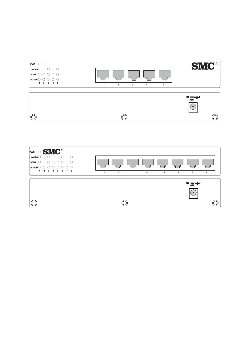
RJ-45-poorten op het frontpaneel
Deze EZ Switch 10/100-modellen beschikken over 5/8 1000BASE-Tpoorten met RJ-45-connectoren die zich op het frontpaneel van de switch
bevinden. Omdat alle poorten automatische MDI/MDI-X-werking
ondersteunen, kunt u straight-throughkabels gebruiken voor alle netwerkverbindingen met pc’s of naar andere switches of hubs.
LED’s op het frontpaneel
Het frontpaneel van de switch is uitgerust met statuslampjes (LED’s)
voor een snelle opvolging van het systeem. In de volgende tabel worden
de functies van de diverse indicatoren gedetailleerd beschreven.
LED’s voor poort- en systeemstatus
LED Staat Status
Spanning Aan De switch ontvangt stroom.
Uit De switch ontvangt geen stroom.
Poorten
Link/Act Aan De poort heeft een geldige netwerkverbinding tot
stand gebracht.
Uit De poort heeft geen geldige netwerkverbinding
tot stand gebracht.
Knipperend Er gaat verkeer door de poort.
1000M Aan Geeft aan dat de poort werkt op 1000Mbps.
Uit Geeft aan dat de poort niet werkt op 1000 Mbps.
10/100M Aan Geeft aan dat de poort werkt op 100 Mbps.
Uit Geeft aan dat de poort werkt op 10 Mbps.
2
Page 6
SMC8505T
EZSwitch 10/100/1000
8505T
EZSwitch 10/100/1000
8508T
CHTERPANEEL
A
SMC8508T
EZSwitch 10/100/1000
8508T
Achterpaneel
De aansluitbus voor gelijkstroomspanning bevindt zich op het
achterpaneel van de switch.
EZSwitch 10/100/1000
1A
1.25A
8505T
3
Page 7

DE
Controleer, voordat u de switch installeert, of alle items beschikbaar zijn
die worden aangegeven onder “Inhoud van de verpakking”. De switch kan
op elk voldoende groot vlak oppervlak of in een standaard EIA 19 inch
rack worden geïnstalleerd.
SWITCH INSTALLEREN
Inhoud van de verpakking
De EZ Switch 10/100/1000 bevat:
• EZ Switch 10/100/1000 (SMC8505T of SMC8508T).
• vier rubberen voetjes.
• kit voor montage in een rack.
• gepaste gelijkstroomadapter.
Een geschikte plaats uitzoeken
Volg zeker de volgende richtlijnen wanneer u een locatie zoekt:
• Vind een gepaste locatie voor de switch:
• Deze locatie moet toegankelijk zijn om de switch te installeren,
te bekabelen en te onderhouden.
• De temperatuur en de vochtigheid moeten zich bevinden
binnen de bereiken die in de specificaties worden opgegeven.
• De statuslampjes (LED’s) moeten duidelijk zichtbaar zijn.
• Er moet aan alle kanten voldoende ruimte zijn
(zowat 5 centimeter) voor de nodige luchtcirculatie.
5
Page 8

SWITCH INSTALLEREN
DE
• Vergewis u ervan dat de twisted-pairkabels zich niet in de nabijheid
bevinden van stroomkabels, apparaten voor neonverlichting en
andere
bronnen van elektrische interferentie zoals radio’s,
zendapparatuur enz.
• Voorzie een goed geaarde stroomaansluiting binnen 2,44 meter
van de switch. Deze aansluiting moet verbonden zijn met een
afzonderlijke zekering. Zoals voor alle apparatuur wordt een filter
of een spanningsbeveiliging aanbevolen.
Instructies
1. De switch plaatsen: voor plaatsing op een tafel of rek bevestigt
u de vier rubberen voetjes op de onderkant van de switch. Voor de
plaatsing op een rack gebruikt u een standaard EIA 19 inch rack
met de meegeleverde kit.
2. De spanning inschakelen: breng het ene einde van de stroomadapter
aan in het contactpunt op het achterpaneel van de switch; het andere
einde in een geschikt stopcontact. Controleer of het spanningslampje
brandt.
Opmerking: Het is niet nodig om de switch eerst uit te schakelen
wanneer u verbindingen met UTP-kabels legt of verbreekt.
Deze handelingen zullen de werking van andere aan de
switch aangesloten apparatuur niet verstoren.
3. Pc’s verbinden: Verbind elke pc met een RJ-45-poort op de switch.
Gebruik hiervoor afgeschermde of niet-afgeschermde twistedpairkabels (UTP of STP) van categorie 5, 5e of 6 van maximaal
100 meter lang. De EZ Switch 10/100/1000 ondersteunt 5/8 pc’s.
Omdat alle poorten automatische MDI/MDI-X-werking
ondersteunen, kunt u straight-throughkabels gebruiken voor alle
netwerkverbindingen met pc’s of naar andere switches of hubs.
6
Page 9

NSTRUCTIES
I
Opmerking: Wanneer een aangesloten toestel geen auto-negotiation
ondersteunt, zal de transmissiesnelheid automatisch
opgespoord worden. De communicatiemodus wordt
standaard op halfduplex ingesteld.
4. Doorverbinden naar switches en andere netwerkapparatuur:
Alle poorten op de switch ondersteunen automatische MDI/
MDI-X-configuratie voor kabelverbindingen. Dit stelt u in de
mogelijkheid om straight-throughkabels te gebruiken om door te
verbinden naar andere switches of hubs vanaf gelijk welke poort
op de switch. Hier zijn geen verdeelkabels of andere instellingen
vereist. Raadpleeg de “Kabelspecificaties” op pagina 11 van deze
gids voor meer informatie hierover.
Opgelet: Breng nooit een verbindingsstuk voor een telefoon aan in
een RJ-45-poort. Dit kan de switch beschadigen. Gebruik enkel
twisted-pairkabels met RJ-45-verbindingsklemmen
in overeenstemming met de FCC-normen.
7
Page 10

SWITCH INSTALLEREN
E
Z
S
w
i
t
c
h
10
/
1
0
0
/
1
0
00
8
50
8T
DE
Toepassingsvoorbeeld
Hieronder staat een typische toepassing van de SMC8505T/SMC8508T
afgebeeld.
EZ Switch 10/100/1000
Server
SMC-EZ109DT
Werkstations
Werkstations
met SMC9452TX
Gigabit PCI Cards
SMC8508T
0
0
0
1
/
0
0
1
/
0
1
h
tc
i
w
S
Z
E
8T
0
85
Notebook
Notebook met
SMC2835W
Wireless PC Card
SMC2804WBR Wireless
Broadband Router
Internet
23
k
n
i
L
1
N
A
L
y
t
i
v
i
t
c
A
N
A
W
N
A
L
W
R
W
P
8
Page 11

P
ROBLEMEN OPLOSSEN
Een diagnose stellen van de indicatoren
1. Symptoom
Het spanningslampje brandt niet wanneer u de stroom heeft
aangeschakeld
Mogelijke oorzaken
• De gelijkstroomadapter kan defect zijn.
Mogelijke oplossingen
• Controleer of alle verbindingen vast zitten.
• Controleer uw stopcontact door er een ander toestel op aan te sluiten.
• Vervang de gelijkstroomadapter.
2. Symptoom
Het verbindingslampje brandt niet wanneer u de verbinding hebt
gelegd.
Mogelijke oorzaken
• De poort van de switch, de netwerkkaart of de kabel zijn mogelijk
defect.
Mogelijke oplossingen
• Controleer of de switch en het verbonden apparaat beide zijn
ingeschakeld.
• Controleer of de netwerkkabel is aangesloten op beide apparaten.
9
Page 12

ROB LEMEN OPLOSSEN
P
• Controleer of een kabel van Categorie 5 of een betere kabel wordt
gebruikt voor verbindingen van 10/100 Mbps, een kabel van categorie
5, 5e of 6 voor verbindingen van 1000 Mbps, en dat de lengte van de
kabels niet meer dan 100 m bedraagt.
• Controleer of de netwerkkaart en de kabelverbindingen niet defect zijn.
• Vervang zonodig de defecte kaart of kabel.
10
Page 13
K
ABELS
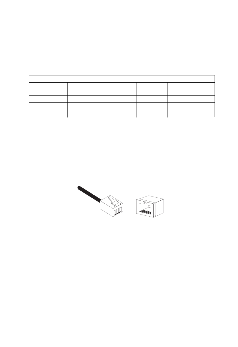
Kabelspecificaties
Kabeltypes en -specificaties
Kabel Type Maximale
lengte
10BASE-T Cat. 3 of beter 100 ohm UTP 100 m RJ-45
100BASE-TX Cat. 5 of beter 100 ohm UTP 100 m RJ-45
1000BASE-T Cat. 5, 5e of 6 100 ohm UTP 100 m RJ-45
Verbindingsklem
10BASE-T/100BASE-TX pintoewijzingen
Opgelet: Breng NOOIT een verbindingsstuk voor een telefoon
aan in een RJ45-poort. Gebruik enkel twisted-pairkabels
met RJ-45-verbindingsklemmen in overeenstemming
met de FCC-normen.
8
1
Gebruik niet-afgeschermde twisted-pairkabels (UTP) of afgeschermde
twisted-pairkabels (STP) voor RJ-45-verbindingen. 100 ohm-kabels van
categorie 3 of beter voor 10 Mbps-verbindingen of 100 ohm-kabels van
categorie 5 of beter voor 100 Mbps-verbindingen Vergewis u er ook van
dat de lengte van een twisted-pairverbinding niet langer is dan 100 meter.
Omdat alle poorten op deze switch automatische MDI/MDI-X-werking
ondersteunen, kunt u straight-throughkabels gebruiken voor alle netwerkverbindingen met pc’s of naar andere switches of hubs. In een straightthroughkabel worden de pinnen 1, 2, 3, en 6 aan het ene einde van de
kabel doorverbonden met pinnen 1, 2, 3, en 6 aan het andere eind van de
kabel.
8
1
11
Page 14

ABELS
K
De volgende tabel geeft een overzicht van de 10BASE-T/100BASE-TX
MDI-X- en MDI-poortpinnen.
Pin MDI-X-signaalnaam MDI-signaalnaam
1 Receive Data plus (RD+) Transmit Data plus (TD+)
2 Receive Data minus (RD-) Transmit Data minus (TD-)
3 Transmit Data plus (TD+) Receive Data plus (RD+)
6 Transmit Data minus (TD-) Receive Data minus (RD-)
4,5,7,8 Niet gebruikt voor 10/100 Mbps Niet gebruikt voor 10/100 Mbps
1000BASE-T pintoewijzingen
De volgende tabel geeft een overzicht van de 1000BASE-T MDI en MDI-X
poortpinnen. Voor deze poorten is het noodzakelijk dat alle
vier de draadparen verbonden zijn. Weet dat voor 1000BASE-T-werking,
alle vier de draadparen gebruikt worden voor zowel zenden als ontvangen.
Gebruik 100 ohm-kabels van categorie 5, 5e of 6, niet-afgeschermde
twisted-pairkabels (UTP) of afgeschermd twisted-pairkabels (STP),
voor 1000BASE-T-verbindingen. Vergewis u er ook van dat de lengte
van een twisted-pairverbinding niet langer is dan 100 meter.
12
Pin MDI MDI-X
Bidirectioneel Data One Plus
1
(BI_D1+)
Bidirectioneel Data One Minus
2
(BI_D1-)
Bidirectioneel Data Two Plus
3
(BI_D2+)
Bidirectioneel Data Three Plus
4
(BI_D3+)
Bidirectioneel Data Three Minus
5
(BI_D3-)
Bidirectioneel Data Two Plus
(BI_D2+)
Bidirectioneel Data Two Minus
(BI_D2-)
Bidirectioneel Data One Plus
(BI_D1+)
Bidirectioneel Data Four Plus
(BI_D4+)
Bidirectioneel Data Four Minus
(BI_D4-)
Page 15

1000B A SE-T
Pin MDI MDI-X
Bidirectioneel Data Two Minus
6
(BI_D2-)
Bidirectioneel Data Four Plus
7
(BI_D4+)
Bidirectioneel Data Four Minus
8
(BI_D4-)
Bidirectioneel Data One Minus
(
BI_D1-)
Bidirectioneel Data Three Plus
(BI_D3+)
Bidirectioneel Data Three Minus
(BI_D3-)
KABELVEREISTEN
1000BASE-T kabelvereisten
Alle UTP-kabels van categorie 5 die gebruikt worden voor 100BASE-TXverbindingen, moeten ook voldoen voor 1000BASE-T, op voorwaarde
dat alle vier de draadparen aangesloten zijn. Het wordt echter aanbevolen,
voor kritische verbindingen of voor nieuwe kabelinstallaties, kabels van
categorie 5e (categorie 5 verbeterd) of 6 te gebruiken. De specificaties
van categorie 5e en 6 houden testparameters in die voor categorie 5 enkel
aanbevelingen zijn. Daarom bestaat de eerste stap bij de voorbereiding
van bestaande bekabeling van categorie 5 voor het gebruik van
1000BASE-T uit een eenvoudige test of de kabelinstallatie beantwoordt
aan de
IEEE 802.3ab-normen.
Het testen van bestaande kabels van categorie 5
Bestaande bekabeling van categorie 5 moet worden getest op verzwakking,
nabij-overspreken (Near-End Crosstalk, NEXT), en veraf-overspreken
(Far-End Crosstalk, FEXT). Alle informatie over deze kabeltests wordt
gespecificeerd in de ANSI/TIA/EIA-TSB-67-norm. Daarnaast moeten
deze kabels ook getest worden op demping (Return Loss, RL) en EqualLevel Far-End Crosstalk (ELFEXT). Deze tests worden gespecificeerd
in het ANSI/TIA/EIA-TSB-95 Bulletin, “The Additional Transmission
Performance Guidelines for 100 Ohm 4-Pair Category 5 Cabling.”
Wanneer u uw bekabeling test, mag u niet vergeten alle verlengsnoeren
tussen switches en eindapparatuur mee in de test te betrekken.
13
Page 16

ABELS
K
Bestaande bekabeling van categorie 5 aanpassen
Wanneer uw bestaande categorie 5-installatie een van de testparameters
voor 1000BASE-T niet haalt, zijn er in principe drie maatregelen die u
kunt treffen om te trachten dit probleem op te lossen.
1. Vervang alle categorie 5-verlengkabels door hoogperformante
kabels van categorie 5e of 6.
2. Verminder het aantal gebruikte verbindingsklemmen.
3. Sluit een aantal gebruikte verbindingsklemmen opnieuw aan.
14
Page 17

P
RODUCT
S
PECIFICATIONS
EZ Switch 10/100/1000
Standards Conformance
IEEE 802.3
IEEE 802.3u
IEEE 802.3x
IEEE 802.3ab
Communication Rate
10, 100, and 1000 Mbps
Communication Mode
Full or half duplex at 10/100 Mbps
Full duplex at 1000 Mbps
Media Supported
10BASE-T: 100-ohm Category 3 or better twisted-pair
100BASE-TX: 100-ohm Category 5 or better twisted pair
1000BASE-T: 100-ohm Category 5, 5e, or 6 twisted-pair
Number of Ports
SMC8505T: 5 RJ-45 1000BASE-T ports
SMC8508T: 8 RJ-45 1000BASE-T ports
Indicator Panel
Power
Ports: Link/Act, 1000M, 10/100M
Dimensions
19.64 x 11.65 x 3.66 cm, (7.76 x 4.6 x 1.44 in)
15
Page 18

ROD UCT SPECIFICATIONS
P
Weigh t
SMC8505T: 0.59 kg (1.309 lbs)
SMC8508T: 0.62 kg (1.378 lbs)
MAC Address Table
8 K entries
Memory Buffer
768 Kbits per unit
Power Consumption
SMC8505T: 12 Watts
SMC8508T: 15 Watts
Power Requirement
DC input
SMC8505T: 12 V, 1 A
SMC8508T: 12 V, 1.25 A
Temper at ure
Operating: 0 ~ 40 ºC / 32 ~ 98 ºF
Storage: -40 ~ 70 ºC / -40 ~ 158 ºF
Humidity
10% to 90% non-condensing
EMC/Safety Compliances
CE Mark
Immunity
EN 61000-4-2/3/4/5/6/8/11
Emissions
FCC Class B, CISPR Class B, EN 61000-3-2/3
Safety
CSA (UL1950, CSA 22.2.950), TUV/GS (EN60950)
16
Page 19

C
OMPLIANCES
FCC - Class B
This equipment has been tested and found to comply with the limits for a Class B digital device,
pursuant to Part 15 of the FCC Rules. These limits are designed to provide reasonable protection
against harmful interference in a residential installation. This equipment generates, uses and can
radiate radio frequency energy and, if not installed and used in accordance with instructions,
may cause harmful interference to radio communications. However, there is no guarantee that
the interference will not occur in a particular installation. If this equipment does cause harmful
interference to radio or television reception, which can be determined by turning the equipment
off and on, the user is encouraged to try to correct the interference by one or more of the following measures:
• Reorient the receiving antenna
• Increase the separation between the equipment and receiver
• Connect the equipment into an outlet on a circuit different from that to which the receiver is
connected
• Consult the dealer or an experienced radio/TV technician for help
EC Conformance Declaration - Class B
SMC contact for these products in Europe is:
SMC Networks Europe,
Edificio Conata II,
Calle Fructuós Gelabert 6-8, 2
08970 - Sant Joan Despí,
Barcelona, Spain.
This information technology equipment complies with the requirements of the Council
Directive 89/336/EEC on the Approximation of the laws of the Member States relating to
Electromagnetic Compatibility and 73/23/EEC for electrical equipment used within certain
voltage limits and the Amendment Directive 93/68/EEC. For the evaluation of the
compliance with these Directives, the following standards were applied:
RFI Emission: • Limit class B according to EN 55022:1998, IEC 60601-1-2 (EMC,
medical)
• Limit class A for harmonic current emission according to
EN 61000-3-2/1995
• Limitation of voltage fluctuation and flicker in low-voltage supply
system according to EN 61000-3-3/1995
Immunity: • Product family standard according to EN 55024:1998
• Electrostatic Discharge according to EN 61000-4-2:1995
(Contact Discharge: ±4 kV, Air Discharge: ±8 kV)
o
, 4a,
i
Page 20

OMPLIANCES
C
• Radio-frequency electromagnetic field according to EN 61000-4-3:1996
(80 - 1000 MHz with 1 kHz AM 80% Modulation: 3 V/m)
• Electrical fast transient/burst according to EN 61000-4-4:1995 (AC/DC
power supply: ±1 kV, Data/Signal lines: ±0.5 kV)
• Surge immunity test according to EN 61000-4-5:1995
(AC/DC Line to Line: ±1 kV, AC/DC Line to Earth: ±2 kV)
• Immunity to conducted disturbances, Induced by radio-frequency
fields: EN 61000-4-6:1996 (0.15 - 80 MHz with
1 kHz AM 80% Modulation: 3 V/m)
• Power frequency magnetic field immunity test according to
EN 61000-4-8:1993 (1 A/m at frequency 50 Hz)
• Voltage dips, short interruptions and voltage variations immunity test
according to EN 61000-4-11:1994 (>95% Reduction @10 ms, 30%
Reduction @500 ms, >95% Reduction @5000 ms)
LV D:
MDD:
• EN 60950 (A1/1992; A2/1993; A3/1993; A4/1995; A11/1997)
• IEC 60601-1
Industry Canada - Class B
This digital apparatus does not exceed the Class B limits for radio noise emissions from digital
apparatus as set out in the interference-causing equipment standard entitled “Digital Apparatus”
ICES-003 of the Department of Communications.
Cet appareil numérique respecte les limites de bruits radioélectriques applicables aux appareils
numériques de Classe B prescrites dans la norme sur le matériel brouilleur: « Appareils
Numériques » NMB-003 édictée par le ministère des Communications.
Safety Compliance
CSA/NRTL (C22.2.950, UL 1950)
EN60950, (IEC 950)
ii
Page 21

OMPLIANCES
C
Wichtige Sicherheitshinweise (Germany)
1. Bitte lesen Sie diese Hinweise sorgfältig durch.
2. Heben Sie diese Anleitung für den späteren Gebrauch auf.
3. Vor jedem Reinigen ist das Gerät vom Stromnetz zu trennen. Verwenden Sie keine Flüssigoder
Aerosolreiniger. Am besten eignet sich ein angefeuchtetes Tuch zur Reinigung.
4. Die Netzanschlu ßsteckdose soll nahe dem Gerät angebracht und leicht zugänglich sein.
5. Das Gerät ist vor Feuchtigkeit zu schützen.
6. Bei der Aufstellung des Gerätes ist auf sicheren Stand zu achten. Ein Kippen oder Fallen
könnte Beschädigungen her vorrufen.
7. Die Belüftungsöffnungen dienen der Luftzirkulation, die das Gerät vor Überhitzung schützt.
Sorgen Sie dafür, daß diese Öffnungen nicht abgedeckt werden.
8. Beachten Sie beim Anschluß an das Stromnetz die Anschlußwerte.
9. Verlegen Sie die Netzanschlußleitung so, daß niemand darüber fallen kann. Es sollte auch
nichts auf der Leitung abgestellt werden.
10. Alle Hinweise und Warnungen, die sich am Gerät befinden, sind zu beachten.
11. Wird das Gerät über einen längeren Zeitraum nicht benutzt, sollten Sie es vom Stromnetz
trennen. Somit wird im Falle einer Überspannung eine Beschädigung vermieden.
12. Durch die Lüftungsöffnungen dürfen niemals Gegenstände oder Flüssigkeiten in das Gerät
gelangen. Dies könnte einen Brand bzw. elektrischen Schlag auslösen.
13. Öffnen sie niemals das Gerät. Das Gerät darf aus Gründen der elektrischen Sicherheit nur
von authorisiertem Servicepersonal geöffnet werden.
14. Wenn folgende Situationen auftreten ist das Gerät vom Stromnetz zu trennen und von einer
qualifizierten Servicestelle zu überprüfen:
a. Netzkabel oder Netzstecker sind beschädigt.
b. Flüssigkeit ist in das Gerät eingedrungen.
c. Das Gerät war Feuchtigkeit ausgesetzt.
d. Wenn das Gerät nicht der Bedienungsanleitung entsprechend funktioniert oder Sie mit
Hilfe dieser Anleitung keine Verbesserung erzielen.
e. Das Gerät ist gefallen und/oder das Gehäuse ist beschädigt.
f. Wenn das Gerät deutliche Anzeichen eines Defektes aufweist.
15. Stellen Sie sicher, daß die Stromversorgung dieses Gerätes nach der EN 60950 geprüft ist.
Ausgangswerte der Stromversorgung sollten die Werte von AC 7.5-8 V, 50-60 Hz nicht über
oder unterschreiten sowie den minimalen Strom von 1 A nicht unterschreiten.
Der arbeitsplatzbezogene Schalldruckpegel nach DIN 45 635 Teil 1000 beträgt 70dB(A) oder
weniger.
iii
Page 22

L
EGAL INFORMATION
AND
C
ONTACTS
SMC's Limited Warranty Statement
SMC Networks Europe ("SMC") warrants its products to be free from defects in
workmanship and materials, under normal use and service, for the applicable warranty
term. All SMC products carry a standard 2 year limited warranty from the date of purchase
from SMC or its Authorized Reseller. SMC may, at its own discretion, repair or replace any
product not operating as warranted with a similar or functionally equivalent product,
during the applicable warranty term. SMC will endeavour to repair or replace any product
returned under warranty within 30 days of receipt of the product. As new technologies
emerge, older technologies become obsolete and SMC will, at its discretion, replace an older
product in its product line with one that incorporates these newer technologies
The standard limited warranty can be upgraded to a 5 year Limited Lifetime * warranty by
registering new products within 30 days of purchase from SMC or its Authorized Reseller.
Registration can be accomplished via the enclosed product registration card or online via
the SMC web site. Failure to register will not affect the standard limited warranty. The
Limited Lifetime warranty covers a product during the Life of that Product, which is
defined as a period of 5 years from the date of purchase of the product from SMC or its
authorized reseller.
All products that are replaced become the property of SMC. Replacement products may be
either new or reconditioned. Any replaced or repaired product carries, either a 30-day
limited warranty or the remainder of the initial warranty, whichever is longer. SMC is not
responsible for any custom software or firmware, configuration information, or memory
data of Customer contained in, stored on, or integrated with any products returned to SMC
pursuant to any warranty. Products returned to SMC should have any customer-installed
accessory or add-on components, such as expansion modules, removed prior to returning
the product for replacement. SMC is not responsible for these items if they are returned
with the product.
Customers must contact SMC for a Return Material Authorization number prior to
returning any product to SMC. Proof of purchase may be required. Any product returned
to SMC without a valid Return Material Authorization (RMA) number clearly marked on
the outside of the package will be returned to customer at customer's expense. Customers
are responsible for all shipping charges from their facility to SMC. SMC is responsible for
return shipping charges from SMC to customer.
WARRANTIES EXCLUSIVE: IF A SMC PRODUCT DOES NOT OPERATE AS
WARRANTED ABOVE, CUSTOMER'S SOLE REMEDY SHALL BE REPAIR OR
REPLACEMENT OF THE PRODUCT IN QUESTION, AT SMC'S OPTION. THE
FOREGOING WARRANTIES AND REMEDIES ARE EXCLUSIVE AND ARE IN LIEU
v
Page 23

EGAL INFORMATION AND CONTACTS
L
OF ALL OTHER WARRANTIES OR CONDITIONS, EXPRESSED OR IMPLIED,
EITHER IN FACT OR BY OPERATION OF LAW, STATUTORY
OR OTHERWISE, INCLUDING WARRANTIES OR CONDITIONS OF
MERCHANTABILITY AND FITNESS FOR A PARTICULAR PURPOSE. SMC NEITHER
ASSUMES NOR AUTHORIZES ANY OTHER PERSON TO ASSUME FOR IT ANY
OTHER LIABILITY IN CONNECTION WITH THE SALE, INSTALLATION,
MAINTENANCE OR USE OF ITS PRODUCTS. SMC SHALL NOT BE LIABLE UNDER
THIS WARRANTY IF ITS TESTING AND EXAMINATION DISCLOSE THE ALLEGED
DEFECT IN THE PRODUCT DOES NOT EXIST OR WAS CAUSED BY CUSTOMER'S
OR ANY THIRD PERSON'S MISUSE, NEGLECT, IMPROPER INSTALLATION OR
TESTING, UNAUTHORIZED ATTEMPTS TO REPAIR, OR ANY OTHER CAUSE
BEYOND THE RANGE OF THE INTENDED USE, OR BY ACCIDENT, FIRE,
LIGHTNING, OR OTHER HAZARD.
LIMITATION OF LIABILITY: IN NO EVENT, WHETHER BASED IN
CONTRACT OR TORT (INCLUDING NEGLIGENCE), SHALL SMC BE LIABLE FOR
INCIDENTAL, CONSEQUENTIAL, INDIRECT, SPECIAL, OR PUNITIVE DAMAGES
OF ANY KIND, OR FOR LOSS OF REVENUE, LOSS OF BUSINESS,
OR OTHER FINANCIAL LOSS ARISING OUT OF OR IN CONNECTION WITH THE
SALE, INSTALLATION, MAINTENANCE, USE, PERFORMANCE, FAILURE, OR
INTERRUPTION OF ITS PRODUCTS, EVEN IF SMC OR ITS AUTHORIZED
RESELLER HAS BEEN ADVISED OF THE POSSIBILITY OF SUCH DAMAGES.
SOME COUNTRIES DO NOT ALLOW THE EXCLUSION OF IMPLIED
WARRANTIES OR THE LIMITATION OF INCIDENTAL OR CONSEQUENTIAL
DAMAGES FOR CONSUMER PRODUCTS, SO THE ABOVE LIMITATIONS AND
EXCLUSIONS MAY NOT APPLY TO YOU. THIS WARRANTY GIVES YOU SPECIFIC
LEGAL RIGHTS, WHICH MAY VARY FROM COUNTRY TO COUNTRY. NOTHING
IN THIS WARRANTY SHALL BE TAKEN TO AFFECT YOUR STATUTORY RIGHTS.
* Under the limited lifetime warranty, internal and external power supplies,
fans and cables are covered by a standard one-year warranty from date of purchase.
Full Installation Manual
Full installation manuals are provided on the Installation CD-Rom. Manuals in other
languages than those included on the CD-Rom are provided on www.smc-europe.com
(section support).
Firmware and Drivers
For latest driver, technical information and bug-fixes please visit www.smc-europe.com
(section support).
vi
Page 24

EGAL INFORMATION AND CONTACTS
L
Contact SMC
Contact details for your relevant countries are available on www.smc-europe.com and
www.smc.com
.
Statement of Conditions
In line with our continued efforts to improve internal design, operational function, and/or
reliability, SMC reserves the right to make changes to the product(s) described in this
document without notice. SMC does not assume any liability that may occur due to the
use or application of the product(s) described herein. In order to obtain the most accurate
knowledge of installation, bug-fixes and other product related information we advise to visit
the relevant product support page at www.smc-europe.com
equipment. All information is subject to change without notice.
before you start installing the
Limitation of Liability
In no event, whether based in contract or tort (including negligence), shall SMC be liable
for incidental, consequential, indirect, special or punitive damages of any kind, or for loss
of revenue, loss of business or other financial loss arising out of or in connection with the
sale, installation, maintenance, use, performance, failure or interruption of its products,
even if SMC or its authorized reseller has been adviced of the possiblity of such damages.
Copyright
Information furnished by SMC Networks, Inc. (SMC) is believed to be accurate and
reliable. However, no responsibility is assumed by SMC for its use, nor for any
infringements of patents or other rights of third parties which may result from its use. No
license is granted by implication or otherwise under any patent or patent rights of SMC.
SMC reserves the right to change specifications at any time without notice.
Trademarks
SMC is a registered trademark and EZ Connect is a trademark of SMC Networks, Inc.
Other product and company names are trademarks or registered trademarks of their
respective holders.
vii
Page 25

Typenummer: SMC8505TX, SMC8508TX V.2
Pub. # 150000005200H R01
 Loading...