

Page 1

1
BARRICADE
TM
ISDN Router
SMC7301TA
User’s Manual
Page 2

2
CHAPTER 1 INTRODUCTI ON........................................................................4
WHAT’S IN THE BOX?....................................................................................... 4
OVERVIEW OF SMC7301TA ISDN ROUTER ................................ ..................... 4
SMC7301TA APPLICATIONS................................ ............................................ 4
Accessing the Internet ..............................................................................5
Supporting Dial-in Access to Your Network .............................................. 5
Creating Your Own Private Wide Area Network ........................................6
SECURITY OVERVIEW ...................................................................................... 6
APHYSICAL LOOK AT THE SMC7301TA ................................ ........................... 7
Rear Panel:............................................................................................... 7
The LEDs on the front ................................ ................................ ...............7
CHAPTER 2 INSTALLING THE SMC7301TA................................ ................. 9
HARDWARE INSTALLATION ................................ ................................ ...............9
SETTING UP AWINDOWS PC FOR CONFIGURING SMC7301TA ........................ 10
CHAPTER 3 INTERNET A CCESS CONFIGURATION ................................ .13
USING DIFFERENT BROWSERS FOR SMC7301TA CONFIGURATION .................. 13
Netscape Navigator 4.x: ......................................................................... 13
Internet Explorer 4.x and 5.x: ................................ ................................ ..14
Logging On ................................ ............................................................. 14
CUSTOMIZING USER INTERFACE FOR YOUR SPECIFIC NEEDS ........................... 15
BASIC INTERNET ACCESS ................................ ................................ .............. 16
INTERNET ACCESS WITH ADVANCED CONFIGURATION.......................................16
Access to/from Remote Site (e.g., Branch Office) ..................................16
DIAL-IN ACCESS FOR OFF-SITE USERS................................ ........................... 17
OVERVIEW OF BROADBAND ROUTER MANAGER SCREEN ................................ .17
Menu Window ................................ ................................ ......................... 18
Configuration Window................................ ................................ .............18
Message Window ................................................................................... 18
System Status Monitoring Window ................................ ......................... 18
WHAT IS A CONNECTION PROFILE?.................................................................19
BASIC INTERNET ACCESS CONFIGURATION VIA WAN .......................................20
BASIC INTERNET ACCESS CONFIGURATION VIA ISDN....................................... 25
Advanced ISDN Configuration ................................................................ 27
IP CONFIGURATION FOR INTERNET ACCESS ................................ .................... 29
THE IP ROUTING TABLE................................ ................................................. 31
Page 3

3
IP ADDRESS TRANSLATION CONFIGURATION ................................ ........ 33
Add or Edit s Set of IP Address Translation ............................................ 34
Delete a Set of IP Address Translation ................................................... 35
STATIC DHCP CONFIGURATION ................................ ................................ .....35
Add or Edit a Set of static private IP address .......................................... 36
Delete a Set of static private IP address................................................. 37
CHAPTER 4 REMOTE OFF ICE ACCESS CONFIGURATION ..................... 38
REMOTE OFFICE ACCESS BY ISDN ................................ ................................ 38
ADVANCED OPTIONS FOR REMOTE OFFICE ACCESS PROFILES ......................... 40
DELETING REMOTE OFFICE ACCESS PROFILE ................................................. 43
CHAPTER 5 DIAL-IN USER ACCESS CONFI GURATION........................... 45
CONFIGURING A DIAL-IN USER PROFILE.......................................................... 45
DELETING DIAL-IN USER PROFILES ................................ ................................ 48
CHAPTER 6 PACKET FILTERING CONFIGURATION .................................49
AN IP PACKET FILTERING OVERVIEW ................................ .............................. 49
ADDING/EDITING/DELETING A PACKET RULE ................................................... 50
CHAPTER 7 MANAGING S MC7301TA ................................ ........................ 53
HOW TO VIEW THE CONNECTION LOG............................................................. 53
HOW TO UPGRADE THE SMC7301TA FIRMWARE ................................ ............54
HOW TO SAVE OR CLEAR CONFIGURATION CHANGES ......................................55
HOW TO RESET SMC7301TA ................................ ................................ .......56
HOW TO CHANGE BROADBAND ROUTER MANAGER PASSWORD ........................ 56
HOW TO CONFIGURE GENERAL SYSTEM SETTINGS.......................................... 58
USING THE COMMAND LINE INTERFACE........................................................... 59
Connecting to the CLI With Telnet ................................ .......................... 59
Connecting to the CLI through the Console Port ................................ ....59
Page 4

4
Chapter 1 Introduction
This chapter gives an introduction to the SMC7301TA ISDN Router.
What’s in the box?
• 1 SMC7301TA ISDN Router,
• 1 AC Adapter,
• 1 ISDN Connector Cable,
• 1 RS-232 Serial Cable (null modem cable for the console port),
• 1 Cat5 Cable,
• 1 CD-ROM containing the user manual,
• 1 Quick Install Guide,
• 1 Warranty and Registration Card.
Overview of the SMC7301TA ISDN
Router
The SMC7301TA ISDN Router is a small desktop router that sits between
your local Ethernet network and a remote network (For example, the Internet
or a remote office). The SMC7301TA contains an ISDN S/T interface, a
10Mbps WAN port, a 10/100Mbps LAN port, and a conso le port for
management capability.
Data comes into the SMC7301TA from the LAN and then is “routed” to
the remote network, and vice versa. In addition to its capability to route IP
traffic, the SMC7301TA also acts as a bridge for other network protocols , such
as Appletalk or SNA.
SMC7301TA Applications
The main functions of the SMC7301TA are to support devices on your
LAN to access the Internet, to support remote users to dial -in and access
resources on your LAN, and to support communications among branch
Page 5
5
offices.
Accessing the Internet
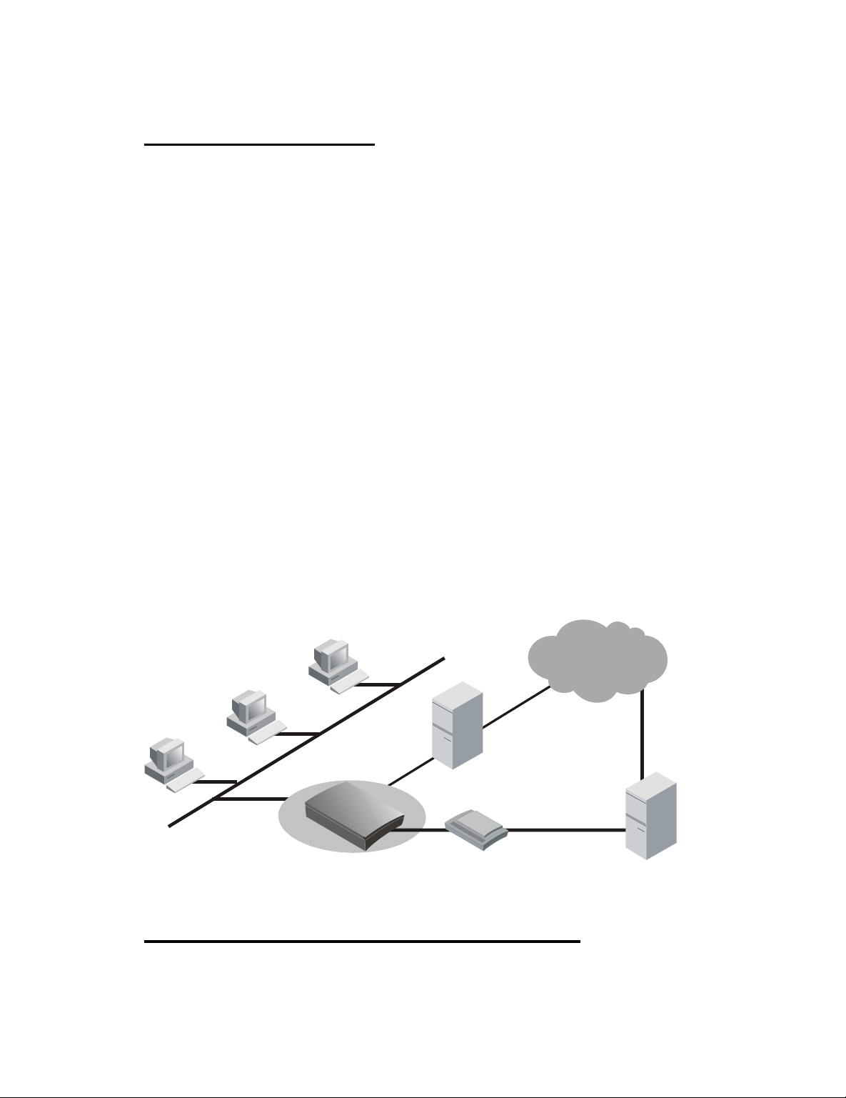
The most common use for the SMC7301TA is to provide Internet access,
so that everyone on your LAN can surf the web, send/receive e -mail, or share
files. The SMC7301TA automatically acquires the necessary IP addre ss when
the connection to the Internet is established. You don’t need to apply for or
assign an IP address to each PC or workstation on your network.
There are two alternatives in establishing the connection between the
LAN and the Internet: either thr ough ISDN or through an xDSL/cable modem.
With built-in PPPoE (Point-to-Point Protocol over Ethernet) support, the
SMC7301TA provides virtual dial -up environments and allows end users to
connect via an xDSL/cable modem to the Internet whenever they wan t.
Alternatively, end users can connect via an ISDN connection to the
Internet. In this situation, the SMC7301TA supports “bandwidth on demand”.
For example, any user’s initial intent to access the Internet will trigger a
B-channel connection to be se t up. As the traffic builds (for example, more
users try to access the Internet, or the same user generates a lot of traffic),
the SMC7301TA will establish the second connection through the other
B-channel. As traffic decreases, one B -channel will be taken down, until finally,
after a configurable period of inactivity, the remaining B -channel will also be
disconnected.
ISDN Router
ADSL /Cable
Modem
ISP
LAN
Internet
ISP
10 M Ethernet
ADSL / Cable
ISDN
Supporting Dial-in Access to Your Network
Under an ISDN connection you can set up your SMC7301TA to allow
users to connect to your ne twork and share resources from their homes while
Page 6
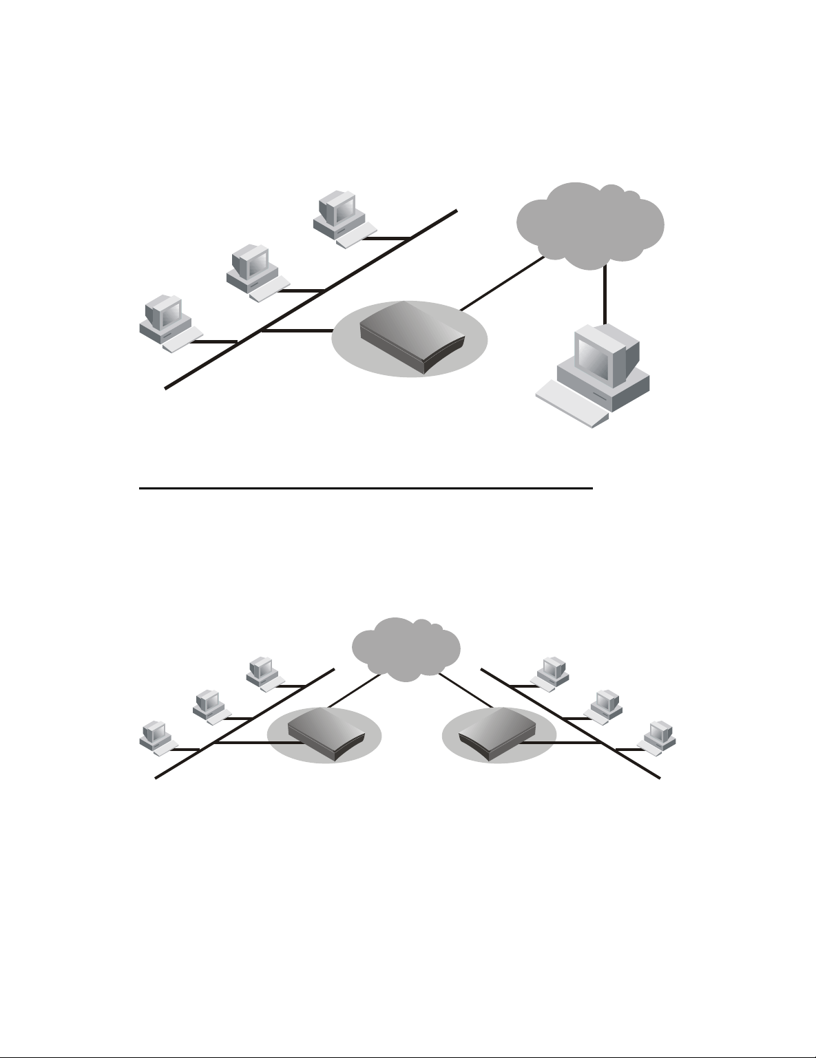
6
they are traveling. The SMC7301TA’s built -in “Broadband Router Manager”
makes the necessary setup a snap. As a security feature, after a user calls in,
the SMC7301TA will hang up and call that user back at a pre-configured
telephone number.
ISDN Router
LAN
Telephone
Network
Dial-in Users
ISDN
ISDN
Creating Your Own Private Wide Area Network
Under an ISDN Connection you can also create your own private wide
area network with the SMC7301TA and allow two or more remote networks to
connect to one another and share resources. The remote network can use an
ISDN router from a different vendor - as long as it also supports LAN -to-LAN
communication.
ISDN Router
Your LAN 1
ISDN
ISDN
Network
ISDN
ISDN Router
Your LAN 2
Security Overview
More and more people are concerned about security of their data in this
Internet era. The SMC7301 TA provides many ways to help make your network
and your data secure:
All dial-in users and LAN -to-LAN communications require
CHAP/PAP/MS-CHAP authentication (basically, user name and
Page 7
7
password).
SMC7301TA also supports call back for dial -in users so that remote
users are really who they say they are.
ISDN Caller ID may be used for incoming call authentication.
SMC7301TA uses a private IP addressing scheme to prevent devices
on your LAN from being accessed by users on the Internet.
Console and Telnet Configu ration provide password protection.
IP packet filtering may be used to enhance security requirements.
A Physical Look at the SMC7301TA
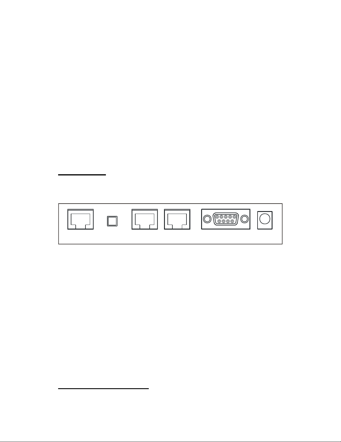
Rear Panel:
The following illustration shows the rear panel of the SMC7301TA:
ISDN S/T TERMINAL
SWITCH
WAN LAN CONSOLE AC 7.5V
One RJ-45 ISDN port for connectio n to your ISDN line.
One RJ-45 10/100 Mbps LAN port for connection to a workstation, or to
another switch or hub.
One RJ-45 10 Mbps WAN port for connection to an xDSL/cable
modem.
One RS-232 DB-9 port to enable console management capability.
One 7.5V AC power connector for connection to an AC power adapter
(included as part of the product).
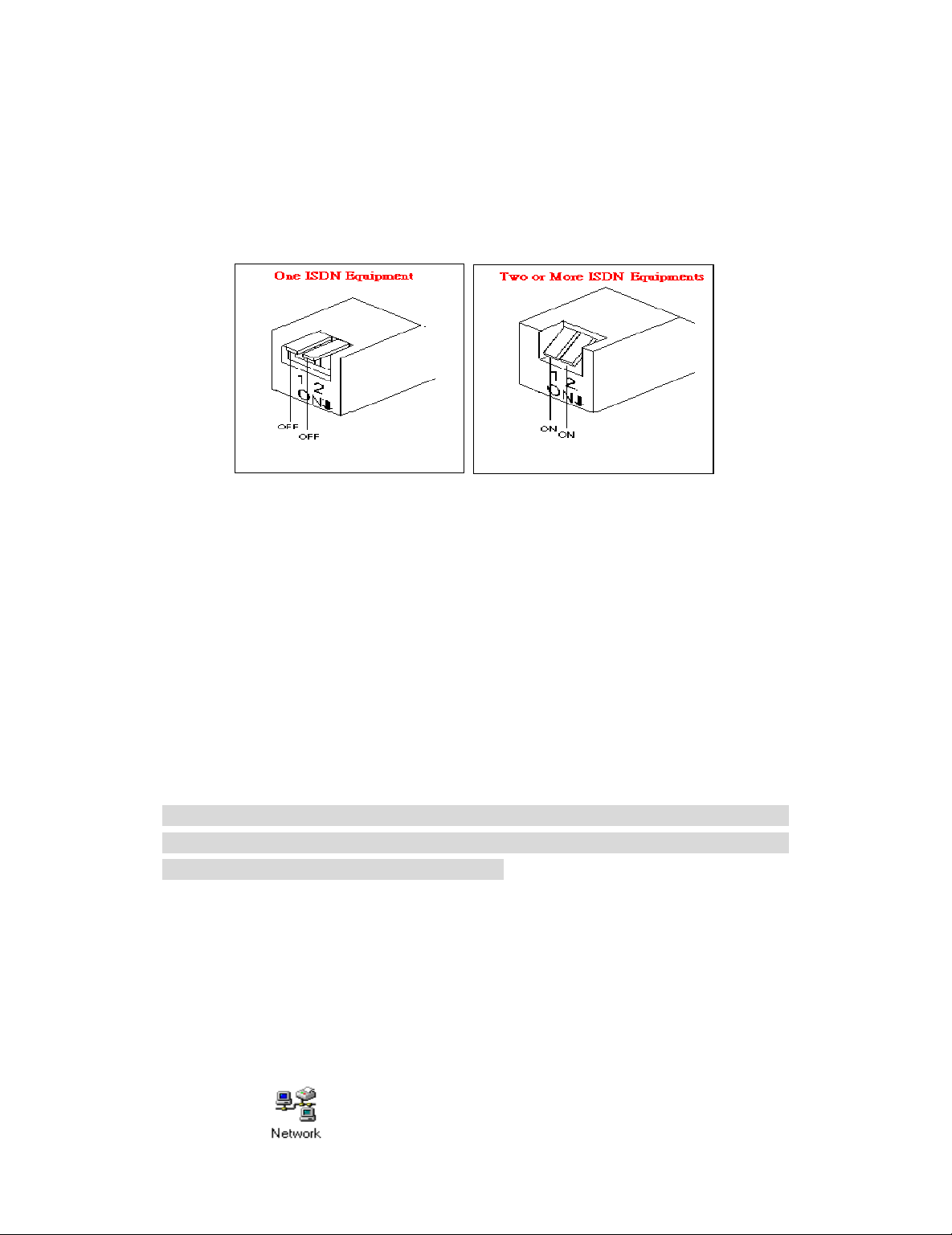
One DIP switch on the rear panel allows you to set the terminating
resistor conveniently if the single ISDN line supports more than one
ISDN terminal equipment at the sa me time.
The LEDs on the front
Page 8

8
There are seven LEDs on the front of the SMC7301TA that show the
status of Power, LAN activity, WAN activity, and ISDN activity. You can tell at a
glance if your SMC7301TA is functioning properly, and if there is any t raffic
passing through. Note that the second, the third, and the forth LED (left to
right when you are facing the front of the SMC7301TA) are dual -colored.
Please note that the third or the forth LED will flash with orange color when
collisions occur on th e LAN port or on the WAN port. The sixth or seventh
LED will flash with green color, respectively, when data is transmitted over the
corresponding B channel. The following table shows a brief description for
each LED.
LAN Interface WAN ISDN
Locatio
n
1234567
8
Functio
n
Powe
r
SPEED10
LAN port
SPEED10
0
LAN port
ACT
LAN port
ACT
WAN port
SYNCB1
B2
Color
GreenGreen
Green
Green
Green
Gree
n
Gree
n
Gree
n
Page 9
9
Chapter 2 Installing the
SMC7301TA
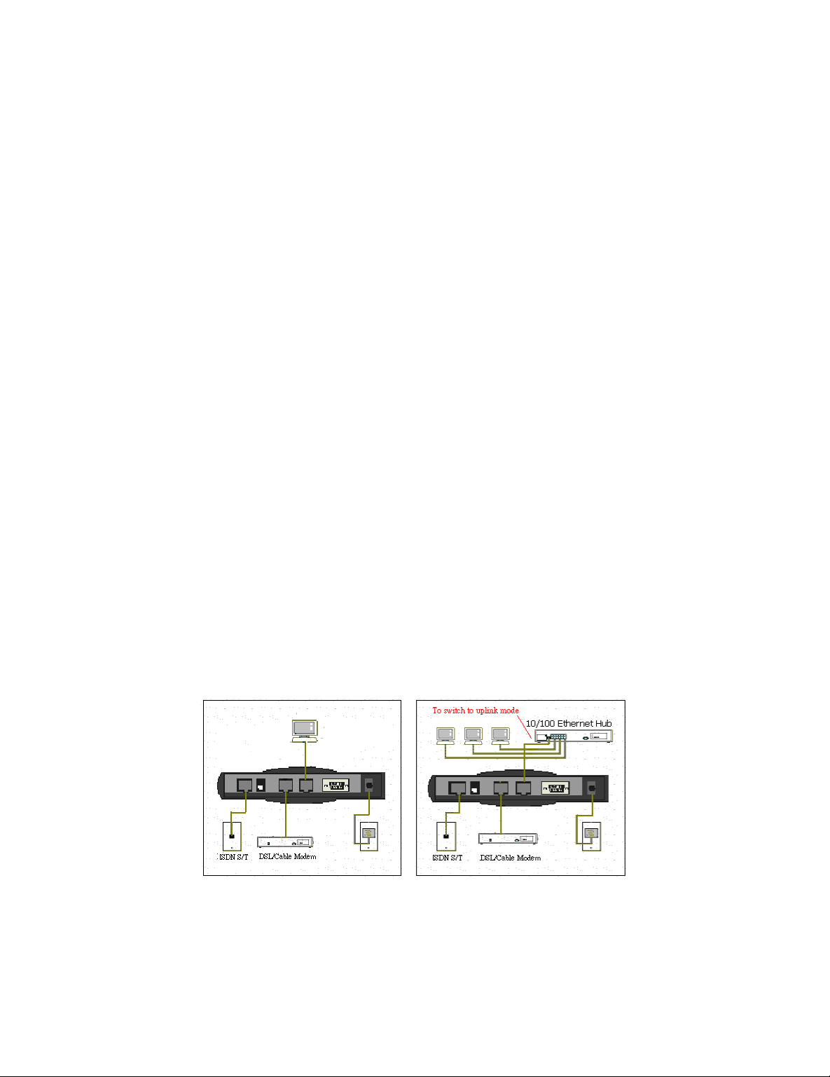
Hardware Installation
Follow these steps to complete the hardware installation for the
SMC7301TA:
Connect the SMC7301TA from the WAN port to an xDSL/cable modem,
or attach an ISDN line to the ISDN port (S/T interface).
Connect your PC to the RJ -45 LAN port. Two or more PCs can be
connected via a multi-port hub or switch which you can connect to the
RJ-45 LAN port of the SMC7301TA.
Plug the power adapter into a wall outlet and the AC connector on the
back of the SMC7301TA.
The RS-232 port is only used to connect a terminal to run the
Command Line Interface using the null modem cable. (This is an
Page 10
10
optional connection.)
There is a DIP switch located on the rear panel for setting the
terminating resistor.
You only need to adjust this switch if ther e are two or more external ISDN
equipment attached to the local telephone line.
Setting Up a Windows PC
This section describes the configuration required by LAN -attached PCs
which communicate with the SMC7301TA, either to configure the SMC7301TA,
or for network access. These PCs must have an Ethernet interface installed
properly, be connected to the SMC7301TA either directly or through an
external hub or switch, and have TCP/IP installed and configured to obtain an
IP address through a DHCP server.
Directly connect a Windows 95/98/2000 PC to the SMC7301TA. If TCP/IP
is not already installed, follow the steps below for its installation.
Note: Any TCP/IP capable workstation can be used to communicate with or
through the SMC7301TA. To configure oth er types of workstations, please
consult the manufacturer’s documentation.
Step 1: Connect your PC to the SMC7301TA’s LAN port or to a hub/switch
that is connected to the SMC7301TA as depicted above. .
Step 2: From the Win95/98 Start Button, select Settings, then Control Panel.
The Win95/98 Control Panel will display.
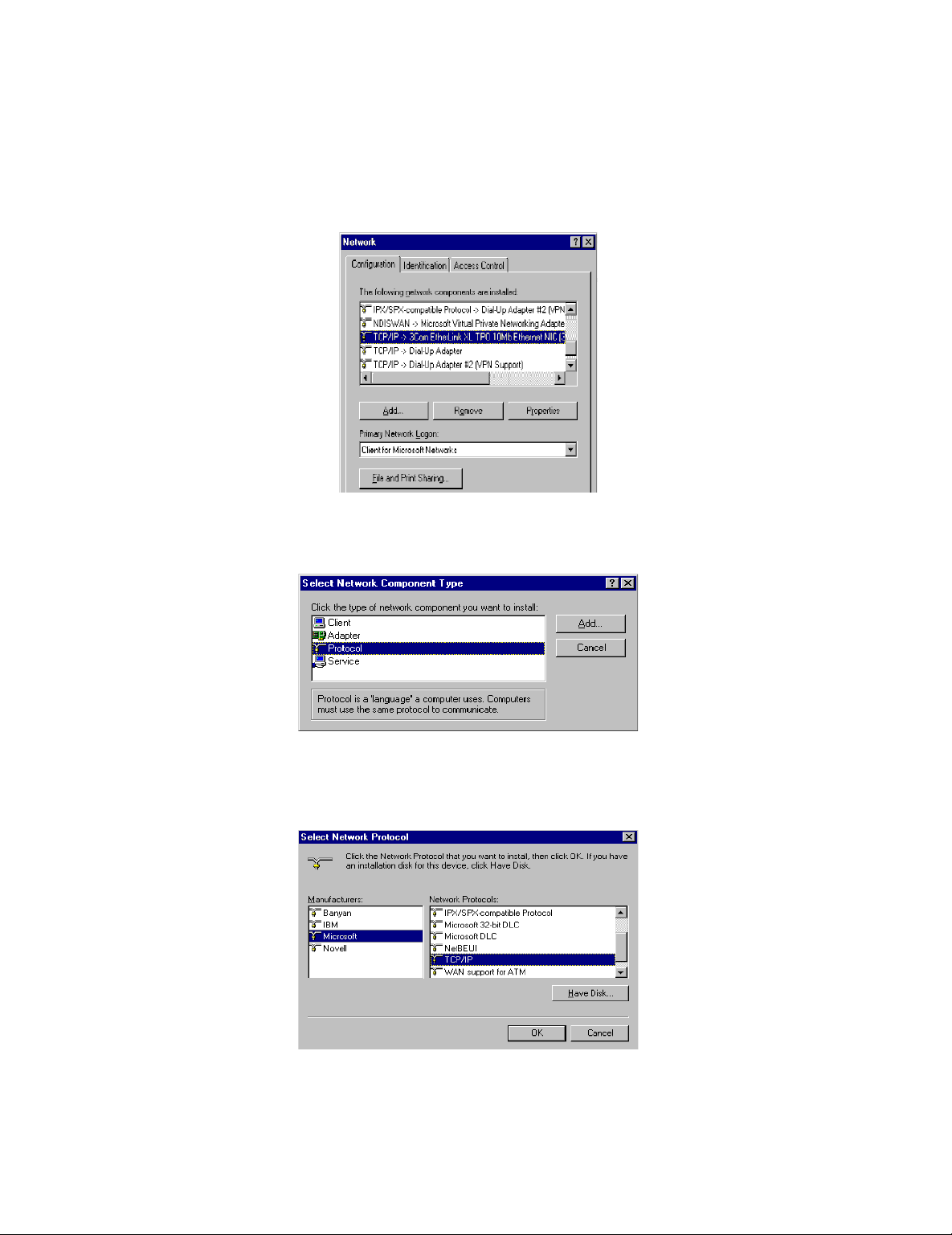
Step 3: Double-click on the Network icon.
Page 11
11
Step 4: Check your list of Network Components in the Network window
Configuration table. If TCP/IP has already been installed, go to Step 8.
Otherwise, select Add to install it now.
Step 5: In the new Network Component Type window, select Protocol.
Step 6: In the new Select Network Protocol window, select Microsoft in the
Manufacturers area.
Step 7: In the Network Protocols area of the same window, select TCP/IP,
then click OK. You may need your Win95/98 CD to complete the installation.
Page 12
12
After TCP/IP installation is complete, go back to the Network window shown
in Step 4.
Step 8: Select TCP/IP in the list of Network Components.
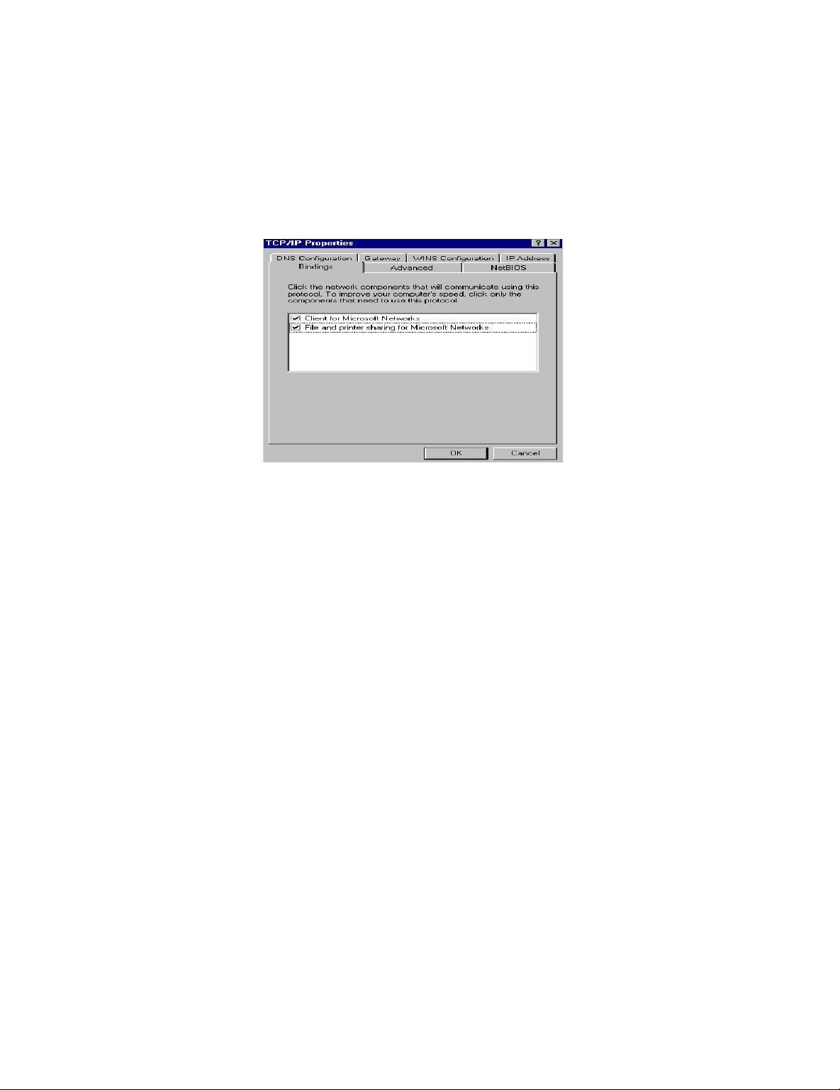
Step 9: Click Properties, and check the settings in each of the TCP/IP
Properties window:
Bindings Tab: both Client for Microsoft Networks and File and
printer sharing for Microsoft Networks should be selected.
Gateway Tab: All fields should be blank.
DNS Configuration Tab: Disable DNS should be selected
IP Address Tab: Obtain IP address automatically should be selected
Step 10: With the SMC7301TA powered on and connected to the LAN, reboot
the PC. After the PC is re -booted, you should be ready to configure the
SMC7301TA. See Chapter 3.
Page 13

13
Chapter 3 Internet Access
Configuration
Once you have completed the installation stage and have configured PCs
in the way described in chapter two, you are ready to configure the
SMC7301TA for actual applications. This chapter describes how to configure
you’re SMC7301TA for basic Internet access, as well as Internet access with
advanced features.
In the following sections you will be shown how to configure the
SMC7301TA for basic Internet acce ss in less than five minutes using the
web-based “Broadband Router Manager”.
Using Different Browsers to
Configure the SMC7301TA
To configure your SMC7301TA, you can use popular browsers such as
Netscape 4.x and Internet Explorer 4.x and 5.x. The fol lowing describes how
to access the “Broadband Router Manager” through IE or Netscape
Navigator.
Netscape Navigator 4.x:
In the Location box (where you normally enter the URL address), enter
Page 14
14
the default private IP address of SMC7301TA followed by hitt ing the return
key:
http://192.168.2.1
Internet Explorer 4.x and 5.x:
In the Address box (where you normally enter the URL address), enter
the default private IP address of SMC7301TA followed by hitting the return
key:
http://192.168.2.1
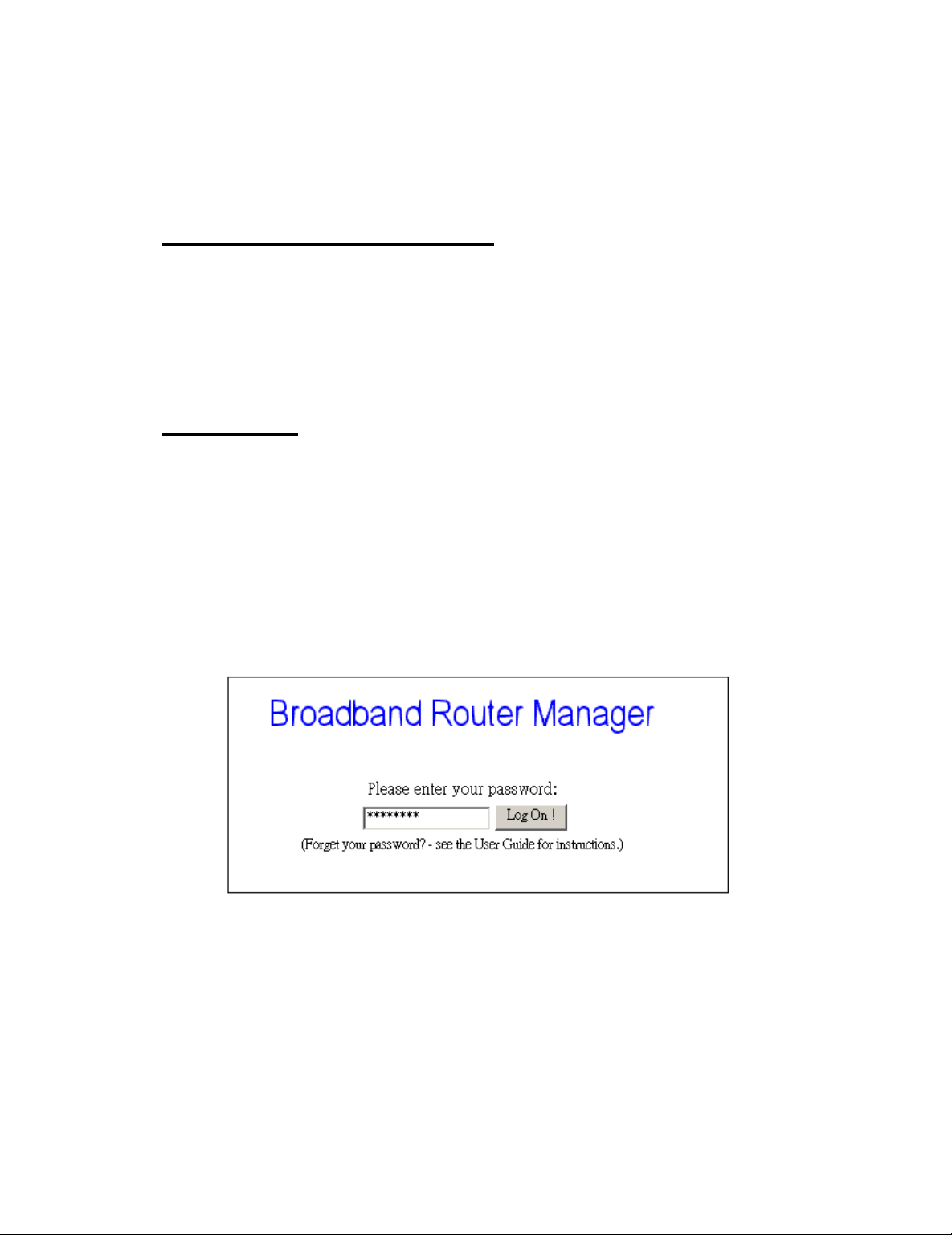
Logging On
A password screen will ask you to log on after you enter the default IP
address described above. If you are logging on for the first time, you should
accept the factory default password (which is “password”). The password is
always displayed as a string of asterisks (“*”). Clicking the Log On button will
begin the Configuration process for the SMC7301TA.
The next time you log in, even if you have modified the password, the
default password (“password”) will still be us ed as the default. You need to
change it to the correct password before you will be let in. No matter what
password you use, each character will always be displayed as a “*”. If you
forget the password, you need to follow the steps described later in the
chapter to be able to log on.
Page 15
15
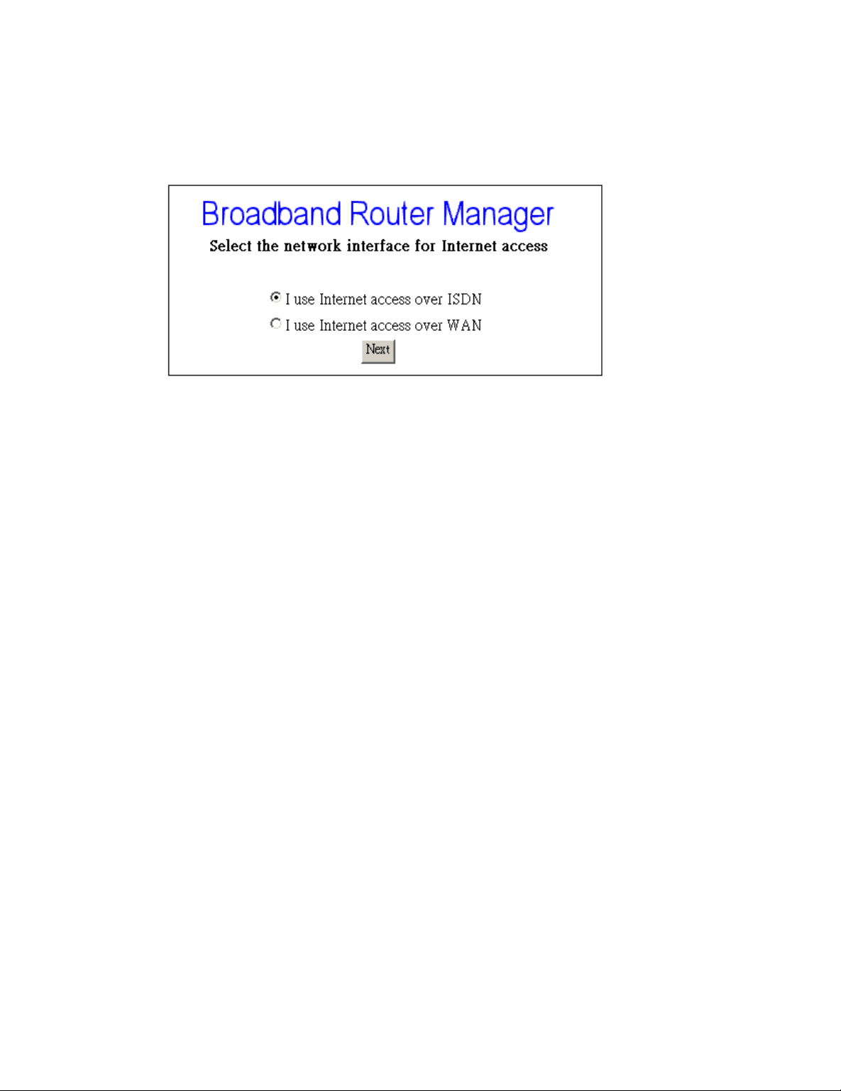
After clicking Log On, the following screen will display, and you must
select either ISDN or WAN as the interface for Internet Access. Click Next to
proceed in the configuration process. Please see the following text for de tails.
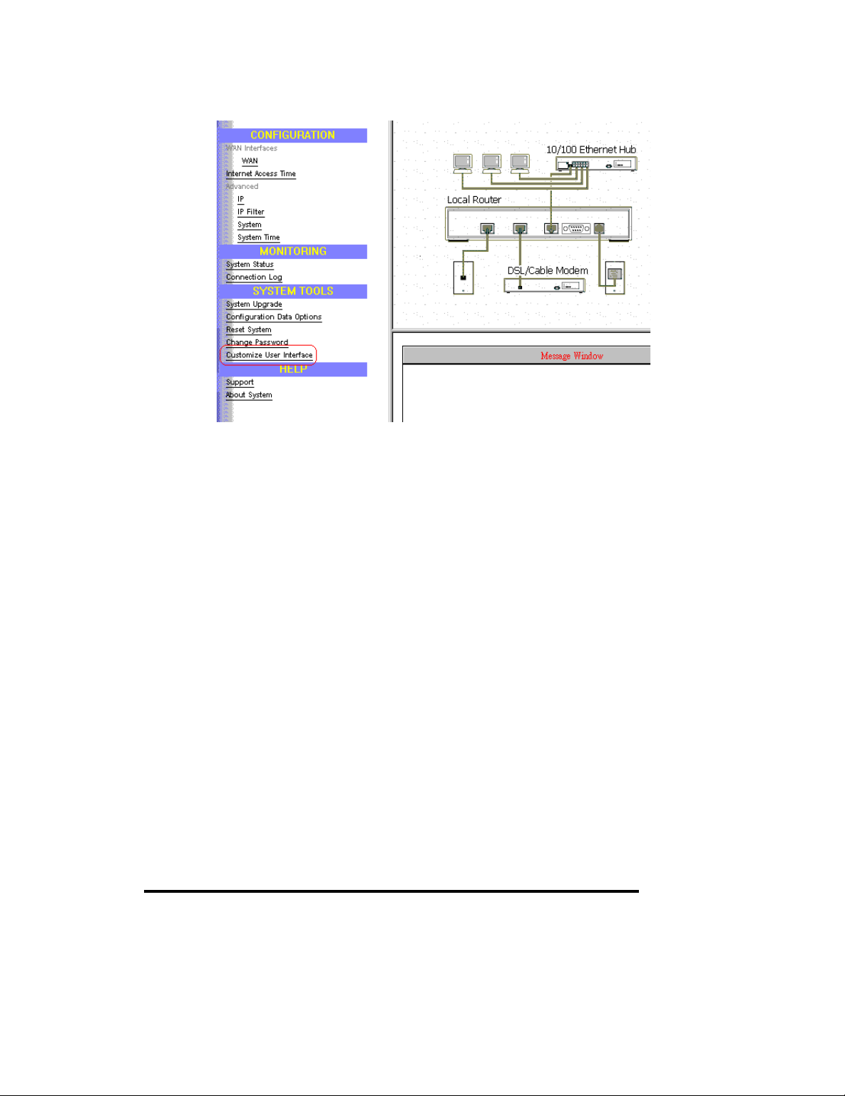
Customizing the User Interface to
Fit Your Specific Needs
When you enter into the main configuration window, click “ Customize
User Interface” in the SYSTEM TOOLS Menu on the left side of the screen,
this will allow you to customize the Broadband Router Manager to suit your
own specific needs. The selections you make determine what configuration
menus and buttons will appear in the screen. For example, if you select Basic
Internet Access only, the interface will only displa y buttons that you need for
basic Internet access.
If you subsequently use Broadband Router Manager to configure the
SMC7301TA for other applications, you can return to this screen to
“re-customize” your interface by selecting Customize User Interface from the
SYSTEM TOOLS Menu.
Page 16
16
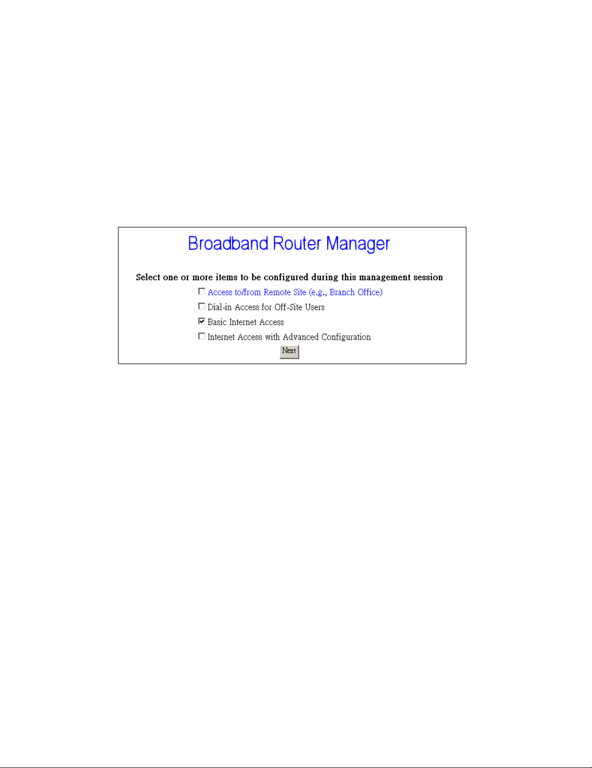
Basic Internet Access
Select this option if you need basic Internet access. This will enable you
to configure Internet Access for all of your LAN users. There are two Internet
access interface selections provided by the SMC7301TA: through ISDN or
through WAN.
Internet Access with Advanced
Configuration
Select this option if you want to configure advanced options, such as
changing the private IP address (for example, when you intend to create your
own private WAN between multiple SMC7301TA routers), or adding a public
IP address (e.g., when you want to install servers on the LAN which are
accessible from the Internet).
Access to/from Remote Site (e.g., Branch Office)
Select this option if you want to create connec tions to other LAN sites,
that is, users at each site can share resources. If you use Windows PCs, for
example, then from the Network Neighborhood facility, you can access files
from remote PCs directly. This feature is valid only when you select ISDN as
Page 17
17
the interface for Internet access.
Dial-in Access for Off-Site Users
Select this option if you want to allow users on a stand -alone computer to
dial in and access resources on your network. This feature is valid only when
you select ISDN as the interfa ce for Internet access.
Click Next when you have selected the options you want. The quantity of
selections is not limited but step -by-step configuration is recommended.
Overview of Broadband Router
Manager Screen
Before you begin the configuration process, take a moment to look at the
Broadband Router Manager screen. Look for these areas:
Menu Window (in the left side of the screen)
Configuration Window (in the right -upper side of the screen)
Message Window (in the right -lower side of the screen)
System Status Monitoring Window (the separate window)
Page 18

18
Menu Window
This part of the browser screen contains items you can click to display the
various screens for configuring your SMC7301TA.
Configuration Window
This is the window where the actual configuration screens appear.
Message Window
Whenever appropriate, the SMC7301TA will display system status or
error messages in this window. For example, when you try to connect to the
Internet, if you had configured your password incorrectly, the message
window will display an appropriate message.
System Status Monitoring Window
This section displays statistics and the status of all interfaces. This
window is invoked as a separate browser screen from the main Broadband
Router Manager browser screen and appears automatically each time you
start Broadband Router Manager . If you close this window, you can always
restart it by clicking System Status in the MONITORING Menu. It does not
contain any toolbars or browser menu buttons. Although the main Broadband
Router Manager screen will timeout, this screen will not, and will continue to
be operational as long as it is active.
Page 19

19
The following statistics are reported for each interface:
Device: lists all interfaces, including both the physical interface as well as
logical connections that have been activated (such as connections to the
Internet or to remote offices).
Status: indicates the current state of the interface: For the LAN, Up means
that the interface is up and functioning, Down means that this interface is not
connected. For WAN or ISDN B channels, if the interface is active, the profile
name is displayed. NoCall means an ISDN B1 or B2 channel is idle.
Xmt Pkts: indicates the number of packets th at have been transmitted
through the interface.
Rcv Pkts: indicates the number of packets that the interface has received.
Err Pkts: indicates the number of error (bad) packets that have been
received.
Disconnect: if an interface has been selected (highlig hted), clicking this
button will cause the connection to be taken down. The LAN interface and the
ISDN physical line are not affected by this operation.
Clear: resets the selected statistic values to zero.
What is a Connection Profile?
To access the I nternet via PPPoE, you need to apply for an account with
an ISP (Internet Service Provider), who will provide you a username and
password that the ISP will use for authentication purposes and will also
Page 20

20
provide all necessary information such as WAN IP Addr ess, Netmask, ISP
Gateway IP Address, DNS IP Address. Alternatively, the SMC7301TA users
can select to access the Internet via ISDN, which you need to apply for an
account with an ISP (Internet Service Provider). The ISP will provide you with
a username and password that the ISP will use for authentication purposes,
and will also provide telephone numbers for dialing -up.
You need to enter such information into a “connection profile” in the
SMC7301TA. Likewise, a connection profile needs to be created fo r each
dial-in user, or for each remote office.
Essentially, a connection profile contains all the information that the
SMC7301TA needs to access the Internet for LAN users, or to support a
remote dial-in user, or to set up a connection with a remote o ffice. Such
information includes dial -up phone numbers, authentication information (the
local user name and password, and possibly the remote site user name and
password), plus other information that may be required for the
communication.
Basic Internet Access Configuration
via WAN
This section describes the steps to set configuration for Basic Internet
Access via WAN.
You will find that the SMC7301TA is optimized for Basic Internet Access.
You don’t need to understand, to apply for or to assign an y IP addresses in
your entire network. The SMC7301TA does these things for you automatically.
You need to configure each device on your LAN in a uniform way as
described in Chapter 2.
What is Basic Internet Access? It means accessing the Internet, surf ing
the web, accessing a remote FTP server (to send or receive files), and
sending and receiving e -mail. These are the tasks that users perform most.
When you apply for an account with your Internet Service Provider (ISP),
you will be given the username, password, and other necessary information.
Follow the steps below.
Step 1: When you logon, select Customize User Interface in the SYSTEM
Page 21

21
TOOLS Menu. Accept the Basic Internet Access selection and click Next.
The following window will be displayed , and select “ I use Internet access
over WAN “. Click Next.
Step 2: Click WAN in the CONFIGURATION Menu.
First you need to make a decision about Obtain IP Address Automatically.
Available options are via PPP over Ethernet, via PPTP, via DHCP , or No. If
you choose No go to step 3. If you choose via DHCP go to step 4, and if you
choose via PPP over Ethernet go to step 5. If you choose via PPTP, go to
step 6.
Step 3: If you choose No for the selection of Obtain IP Address
Automatically. The following screen will be displayed. Enter the following
information and then Click Apply.
Page 22

22
Profile Name: the name that you will use to identify this Internet access
profile.
WAN IP Address: the IP address of your WAN.
WAN IP Netmask: the IP Netmask of your WAN.
ISP Gateway IP Address: the IP Address of your ISP Gateway
Primary DNS IP Address: the IP Address of your Primary DNS.
Secondary DNS IP Address: the IP Address of your Secondary DNS
Step 4: If you choose via DHCP for the selection of Obtain IP Address
Automatically. The following screen will be displayed. Enter the following
information and then Click Apply.
Profile Name: the name that you will use to identify this Internet acce ss
profile.
(Optional) Host Name (System Name): the Host Name provided by your
Page 23

23
system.
Step 5: If you choose via PPP over Ethernet for the selection of Obtain IP
Address Automatically. The following screen will be displayed. Enter the
following information and then Click Apply and Test.
Profile Name: the name that you will use to identify this Internet access
profile.
Obtain IP Addresses Automatically: get the IP Address via PPP over
Ethernet. Some DSL -based ISPs use PPPoE to establis h communications
with an end-user. If you are connected to the Internet through a DSL line,
check with your ISP to see if they use PPPoE
ISP Account Name: the username of your ISP account
ISP Account Password: the password of your ISP account
(Optional) Service Name: Enter the Service Name provided by your ISP if it
is required.
(Optional) Access Concentrator Name: Enter the Access Concentrator
Name provided by your ISP if it is required.
Idle Timeout (0-3600 seconds): The default value of the idle timeout is 120
seconds. It represents the number of seconds of inactivity over the connection:
when this value is reached, the SMC7301TA will disconnect the connection.
You can change the idle timeout value to anything between 0 to 3600 seconds.
But if you select 0, the connection will never be timed out.
Page 24

24
Step 6: If you choose via PPTP for the selection of Obtain IP Address
Automatically. The following screen will be displayed. Enter the following
information and then click Apply and Test.
Profile Name: The name that you will use to identify this Internet accesses
profile.
Obtain IP Addresses Automatically: Obtain the IP address from ISP using
PPTP connection to the local cable modem or ADSL modem. Some
DSL-based ISPs use cable modem/ADSL m odem as PPTP server to
establish communications with an end -user. Check with your ISP to see if
PPTP is used.
PPTP Local IP Address: IP address of SMC7301TA router for the PPTP
connection. Consult your ISP for this information.
PPTP IP Netmask: IP network mask for the PPTP Tunnel. Consult your ISP
for this information.
PPTP Remote IP Address: IP address of the broadband modem for the
PPTP Tunnel. Consult your ISP for this information.
ISP Account Name: the username of your ISP account
ISP Account Passw ord: the password of your ISP account
Idle Timeout (0-3600 seconds): The default value of the idle timeout is 120
seconds. It represents the number of seconds of inactivity over the connection:
when this value is reached, the SMC7301TA will disconnect the connection.
You can change the idle timeout value to anything between 0 to 3600 seconds.
But if you select 0, the connection will never be timed out.
Page 25

25
Note 1: When you click Apply or Apply and Test, the SMC7301TA connects to
your Internet Service Provider. Watch the Message Window for any messages.
If the test is successful, your users will be ready to access the Internet. If
not,the SMC7301TA will try to give you enough information to let you know
why the connection is not successful.
Note 2: If you are using Alcatel’s ANT (ADSL Network Termination) in the
French market as your broadband router, please select “via PPTP” in the
Obtain IP Address Automatically field.
Basic Internet Access Configuration
via ISDN
This section describes the steps require d for Basic Internet Access via
ISDN. When you apply for an account with your Internet Service Provider
(ISP), you will be given the necessary information, including your account
name, account password, and the ISP’s local access ISDN telephone number.
Have these available and then follow the steps below.
Step 1: When you logon, select Customize User Interface in the SYSTEM
TOOLS Menu. Accept the Basic Internet Access selection and click Next.
The configuration window will be displayed,
Step 2: Select I use Internet Access over ISDN and then click Next.
Page 26

26
Step 3: Select ISDN in the Configuration Menu and the following screen will
appear.
Step 4: Select the ISDN switch type that your ISP has p rovided you.
Step 5: Select the number of the directory phone numbers and enter the
directory phone numbers in the corresponding blanks.
Step 6: Enter the following information:
Remote Phone Number: the ISDN telephone number of your ISP.
ISP Account Name: the username of your ISP account.
ISP Account Password: the password of your ISP account.
Step 7: Click Apply and Test.
Note: When you click Apply and Test, the SMC7301TA attempts to place a
call to your Internet Service Provider. Watch the Message window for any
messages. If the test is successful, your users will be ready to access the
Internet. If not, the SMC7301TA will try to give you enough information to let
you know why the connection was not successful.
After the successful Apply and Test, any users in the LAN should restart
Page 27

27
their PCs. Now you can surf in the Web, receive E -mails, or transmit files. For
more advanced configurations, refer to the following text.
Advanced ISDN Configuration
After completing basic Internet access configur ations via ISDN, now you
can set advanced ISDN Configuration if you go back to the Broadband
Router Manager screen and select Internet Access with Advanced
Configuration
Step 1: After entering the following parameters as the way descr ibed in the
previous section, click Advanced.
Step 2: The following configuration window will appear.
Page 28

28
Step 3: Set Multilink Usage parameters. This determines how the
SMC7301TA utilizes the two B channels for your Internet connection.
Available options are:
One B Channel Only: SMC7301TA will only use one B channel.
Two B Channels Only When Needed: SMC7301TA will initiate a connection
with one B channel, and bring up the other B channel only if the traffic
increases to a point when more bandwidth is n eeded.
Always two B Channels: SMC7301TA will always establish both B Channels
to access the Internet.
Step 4: Select Data Service. Available options are Data Over Voice Channel ,
64K, 56K, and Auto. Recommended selection is Auto.
Step 5: Enter Remote Sub Address Number if necessary.
Step 6: Select STAC compression option.
Step 7: Set Idle Timeout number. The range is from 0 to 3600 seconds.
Step 8: Select Advice of Charge Support option and enter the Unit Price
and Currency in the corresponding blanks if th e selection is Yes.
Step 9: Click OK to return to the main configuration screen and skip to next
step. Otherwise click Alternative Number if there is one or more alternative
remote phone numbers. Enter the alternative remote phone number in the
corresponding blanks. Then press OK to return to the previous screen. Again
press OK to return to the main configuration screen.
Step 10: Click Apply and Test
Page 29

29
Note: When you click Apply and Test, the SMC7301TA attempts to place a
call to your Internet Servi ce Provider and log in. Watch the Message Window
for any messages. After the test is successful, the SMC7301TA will disconnect
from your ISP. If it is not successful, make any necessary changes based on
progress messages that appear in the message window, and try again.
After Apply and Test is successful, any users on your LAN who want to
access the Internet should configure their PCs or workstations in the way
described in Chapter 2. Then, they must reboot their workstations in order to
update them with information that the SMC7301TA learned from the ISP
during the Apply and Test operation.
IP Configuration for Internet Access
Using the IP option in the Menu Window, you can assign a public IP
address to the SMC7301TA, modify the private IP addre ss of the SMC7301TA,
modify DNS addresses, and enable or disable DHCP.
Step 1: Select Internet Access with Advanced Configuration from
Broadband Router Manager . Then click IP from the Menu Window.
Step 2: The System IP Configuration screen appears:
Page 30

30
Note: To install public servers on your network (For Example, Web or ftp
servers), you need to apply for an IP address for each server plus one for the
LAN port of the SMC7301TA. All these public IP addresses have to belong to
the same IP network.
Set the following parameters:
Public IP Address: the public IP address for the LAN interface on the
SMC7301TA.
Public IP Netmask: the network mask for the public network address on your
LAN.
Private IP Address: the private IP address for the LAN interface on the
SMC7301TA. The default private IP address is 192.168.2.1. If you want to
create your own private network through other SMC7301TA with remote
offices, you need to make sure that each SMC7301TA on each LAN is
assigned a unique private IP net work address. However, please note that
once you change the private IP address (such as from the default of
192.168.2.1 to 192.168.1.1) either from the browser or through a telnet
session (which is based on the IP address), the device from which you
operate will no longer be able to communicate with your SMC7301TA. To
reconnect, you need to restart your device to allow it to acquire the new
private IP address from the SMC7301TA, and then your device can again
communicate with your SMC7301TA. For the same re ason, all devices on the
Page 31

31
LAN need to be restarted before they can access the Internet again.
Private IP Netmask: the network mask for your private network. Its value is
255.255.255.0, and cannot be changed.
Primary DNS IP Address: the IP address of the pri mary Domain Name
Server (DNS). If properly configured, when a device reboots and acquires the
IP address from the SMC7301TA, the IP addresses of both the primary and
the secondary DNS server will be provided for client workstations or PCs.
Secondary DNS IP Address: the IP address of the secondary domain name
server.
Note: When an SMC7301TA connects to the ISP, it will automatically be
assigned the IP address for a primary Domain Name Server (DNS) , as well
as the IP address for a secondary DNS. Alternative ly, the user can decide to
assign their own DNS IP addresses.
DHCP: enables or disables the SMC7301TA’s Dynamic Host Configuration
Protocol (DHCP) feature. If you want the SMC7301TA to act as a DHCP
server and assigns private IP addresses to any requestin g DHCP client, make
sure DHCP is enabled. When enabled, the SMC7301TA will provide an IP
address, network mask, gateway address (SMC7301TA’s private IP address),
and DNS addresses to any workstations on the local area network that are
configured as a DHCP client. Devices on your network that are configured
with public IP addresses are not DHCP clients. Therefore, you need to assign
their IP addresses, network mask, default gateway IP address, primary and
secondary DNS IP addresses manually.
IP Address Assignment-High & Low: the maximum and minimum private IP
address which can assigned to each client PC or workstation in the LAN. The
range is from 1 to 254.
Step 3: Click Routing, Address Translation or Static DHCP if it is necessary
to set these configurations. Otherwise click Apply to confirm the configuration
and return to the main configuration screen.
The IP Routing Table
The IP Routing Table contains all the information that the SMC7301TA
needs to route an IP data packet. You can view the IP Routi ng Table by
Page 32

32
clicking on the Routing button at the bottom of the Advanced Internet Access
Setup screen (described in the previous section). From this screen, you can
also add new routing entries to the table. The following screen shows an
example of the IP Routing Table.
When an IP packet arrives in the SMC7301TA, IP tries to determine if the
destination IP address contained in the packet is within the network defined by
the “Dest IP” and “Netmask” pair of an entry in the routing tab le. If a match is
found, the packet is forwarded to the interface or profile specified in the
“IfName” field. The “Hops” field is the number of routers the packet must travel
through in order to reach its final destination. If this value is zero, the
destination is in a network directly attached to this router, such as a LAN.
If no match is found with a destination network, then a special entry
called the “Default IP Route” is used. This normally is set to a path where
another router can be reached that has additional information about other
networks not known to the Broadband Router, such as the interface to the
Internet. If no match is found and a default IP route is not defined, the IP
packet is discarded and will go nowhere.
An entry for a specif ic host or network may be added manually. This
“Static Route” is indicated by an “S” in the Flag’s field. Other flag field entries
are “H” for host, and “G” for gateway.
Note: To delete a static route, select it in the routing table and click the Delete
button. You cannot delete Host or Gateway routes.
Page 33

33
Follow the steps to add or to change the default route or add a static
route:
Step 1: Click the Add button in the IP Routing Table screen to display the
following screen:
Step 2: Enter the following information:
Default Route: select if you want to specify a new default route. Note that the
Remote IP Address and Remote IP netmask fields do not appear if you select
this option.
CAUTION: Misconfiguring the default route may result in abnormal system
behavior and/or unnecessary telephone charges.
Static Route: select if you want to add a static route.
Remote IP Address: the remote IP address of the new route.
Remote IP Netmask: the IP netmask of the new route.
Gateway: identifies if the gateway is an IP address or interface.
Hop Count: the maximum number of hops for this route.
Step 3 Click APPLY.
IP Address Translation
Configuration
Page 34

34
For security and economic purposes, the SMC7301TA supports Single
User Account feature (SUA). Multiple users in the LAN can share a public IP
address from an ISP, and the whole LAN will be viewed as a big “device” by
Internet users. However, servers in the LAN are allowed to provide services to
the Internet users if you properly configure the server’s p rivate IP address
“translated” to the corresponding service port number. For example, you can
set the FTP server’s private IP address mapped to port 21. Follow the steps
and the SMC7301TA will automatically complete the mapping procedure.
Note: Remember to set a fixed private IP address for each server providing
services to the Internet users, i.e., these servers can’t be DHCP clients.
Add or Edit an IP Address Translation
Step 1: Click Address Translation button in the Advanced Internet Access
Setup screen. The following IP Address Translation Configuration screen
will appear.
Step 2: Click Add for adding an IP address translation, or click Edit for editing
an existing IP address translation after selecting the IP address translation
that you want to edit. The Following screen will appear.
Page 35

35
Step 3: Enter the following parameters.
Add Address Translation: Available options are Default Enter and Static
Entry.
Public Port Number: The public port number corresponding to the service
that the specific server provides.
Private IP Address: The private IP address that you want to assign to the
server.
Private Port Number: The private port number corresponding to the service
that the specific server provides. Public Port Number and Private Port Number
should be the same.
Step 4: Click Apply.
Delete an IP Address Translation
Step 1: Select the IP address translation that you want to delete from the IP
Address Translation Configuration screen.
Step 2: Click Edit.
Static DHCP Configuration
By the built-in DHCP feature, the SMC7301TA can automatically assign a
private IP address to each PC or workstation in the LAN. But under some
situations, you need to set a static private IP address for certain PCs or
workstations. Follow the steps to as sign a static private IP address to a PC or
a workstation.
Page 36

36
Note: Remember to properly set network configurations from the operating
systems on the PCs or workstations to whom you want the SMC7301TA to
assign a static private IP address.
Add or Edit a Static Private IP address
Step 1: Click Static DHCP from Advanced Internet Access Setup Screen. The
following screen will appear.
Step 2: Click Add for adding a static private IP address, or click Edit for
editing an existing static private IP address afte r selecting a new static private
IP address. The following screen will appear.
Name: A name is assigned for router manager identification purpose.
IP Address: The static private IP address that you want to assign.
MAC Address: The MAC address of the physical interface between the
SMC7301TA and the PC or workstation.
Page 37

37
Step 3: Click Apply.
Delete a Static Private IP address
Step 1: Select a static private IP address that you want to delete form the
DHCP Configuration window.
Step 2: Click Delete.
Page 38

38
Chapter 4 Remote Office
Access Configuration
In order for the local LAN users to access a remote LAN, you need to
configure a connection profile for the router on each site (the remote router
and the Broadband Router). Note that the remote site does not have to have a
SMC7301TA router, and may not be configurable by the local administrator. In
either case , make sure the configuration of SMC7301TA matches the
requirements of the remote site.
Remote Office Access by ISDN
To configuring the ISDN interface for Remote Office connectivity, follow
these steps:
Step 1: Select Access to/from Remote Site in the Broadband Router
Manager screen and click Next:
Step 2: If you have already conf igured your ISDN interface, skip to Step 3.
Otherwise, configure your ISDN interface in the way described in the chapter
3.
Step 3: Click Connection Profiles in the Menu Window. The Connection
Profile Summary window will appear if there was connection prof ile
configured previously.
Page 39

39
Step 4: Select New and Click Next , the Connection Profile Configuration
window should appear as follows,
Step 5: Enter the following information :
Profile Name: a name associated with this profile.
Call Direction: if the remote site will be dialing in, select Incoming. If the
SMC7301TA will dial out to the remote site, select Outgoing. Select Both if
either side can initiate the connection. The default setting is Both.
Note: If you set Call Direction to Incoming, the Remote Phone Number,
My System Name, and My System Password fields will not display unless
Call Back is Yes. If only incoming calls are allowed with this profile, the
APPLY and TEST button will not display. If you set Call Direction to
Outgoing, the Call Back fields will not display.
Call Back: if Call Back is enabled ( Yes is selected), the SMC7301TA checks
the Remote System Name and Remote Password. If a call is received and
authentication succeeds, the SMC7301TA disconnects the incoming call, and
calls the number in the Call Back field. If Call Back is not enabled (No), the
Call Back Number field will not display. If the Call Direction is Outgoing only,
Call Back options will not display.
Remote Phone Number: the ISDN phone number of the remote router
Page 40

40
connected to the remote LAN.
My System Name: the name that the remote system will use to recognize
your network. This field is case sensitive.
My System Password: the password the remote system will use to
authenticate your system. This field is case sensitive.
Note: Make sure the remote site is configured with the same values you
specify in My System Name and My System Password .
Remote System Name: the name of the remote network that will dial in. This
field is case sensitive.
Remote System Password: the password that your SMC7301TA will expect
to see from the remote system. Note that authentication is CHAP, PAP, or
MS-CHAP, meaning that CHAP will be used to authenticate the incoming call
first. If CHAP fails, then PAP will be used. If PAP fails again, then MS -CHAP
will be used.
Step 6: If you selected Outgoing or Both as your Call Direction, click
APPLY and TEST, or select ADVANCED for more options. You must still click
Apply and Test even if the other end of the connection has not been
configured. In this case the test will fail, but that can be considered normal.
Note: When you click APPLY and TEST, the SMC7301TA attempts to place a
call to your remote site and log in. Watch the Message Window for any
progress messages. After the test is successful, the SMC730 1TA will
disconnect from your remote site. If it is not successful, you can make any
necessary changes based on progress messages that appear in the message
window, and try again.
Advanced Options for Remote
Office Access Profiles
If you press the Advanced button from the above Connection Profile
Configuration , the following screen appears.
Page 41

41
Step 1: Set any of the following parameters:
Data Service: choose 64K, 56K, or Auto. Select Auto unless you know the
speed required by the other end of the con nection requiring either 64K or 56K.
Remote Sub-Address: Enter sub-address number in the remote site if
necessary.
Caller ID Authentication: select Yes if you want the SMC7301TA to check
the caller ID before accepting the call. This service may require a special
agreement with your ISDN service provider.
Caller ID Number: if you enabled Caller ID Authentication, enter the expected
Caller ID Number in this field.
STAC Compression: allows outgoing data to be compressed to achieve
higher throughput, and compr essed incoming data to be recognized. The
ability to use compression depends on the capabilities of the ISP.
Idle Timeout: the number of seconds of inactivity over the connection. When
this value is reached, SMC7301TA will disconnect the call. You can set the
idle timeout from 0 to 3600 seconds. The default setting is 120 seconds. If you
select 0, the connection will never be timed out.
Enable IP: select Yes to allow IP routing over a connection using this profile.
IP RIP: enable or disable IP Routing Infor mation Protocol. Available RIP
options are RIP1 and RIP2
Remote IP Address: the IP address of a destination computer on a network
reachable through this connection.
Remote IP Netmask: the IP subnet mask of the Remote IP Address.
Enable Bridging: select Enable to bridge other protocols, for example, SNA,
Page 42

42
Appletalk, and NetBEUI.
Step 2: If advanced configuration is required for the operation of ISDN, and its
load sharing capabilities, then click Multilink. Alternatively skip to step 4.
Step 3: Click OK after completing the parameters in the following windows.
Multilink Usage: determines how the SMC7301TA utilizes the two B channels
in your ISDN connection. Options are:
One B Channel Only: SMC7301TA will only use one B channel, regardless of
the traffic.
Two B Channels Only When Needed: SMC7301TA will initiate a connection
with one B channel, and only bring up the other B channel if the traffic
increases beyond the capacity of the first B channel.
Always two B Channels: SMC7301TA will always use both B chan nels,
regardless of traffic.
Depending on the selection of the ISDN link usage, the following options may
be offered.
Upper utilization threshold: determines when the SMC7301TA will activate
the second ‘ B’ channel.
Lower utilization threshold: determines when the SMC7301TA will drop the
second “B” channel call.
Optional 2nd Remote Phone Number: required if the remote site requires
two separate numbers for dial in access.
Step 4: Skip to step 6 or click Alternative Numbers if it is required to set
more than one choice of remote phone numbers. The screen will appears as
follows,
Page 43

43
Step 5: Select the Number of the Alternative Remote Phone Numbers and
then enter the remote phone numbers in the corresponding blanks. Click OK
to go back to the previous screen.
Step 6: Click OK to go back to the main configuration screen and click Apply
and Test.
Note: When you click APPLY and TEST, the SMC7301TA attempts to place a
call to your remote site and log in. Watch the Message Window for any
progress messages. After the test is successful, the SMC7301TA will
disconnect from your remote site. If it is not successful, you can make any
necessary changes based on progress messages that appear in the message
window, and try again.
Deleting Remote Office Access
Profile
Follow the steps to delete a Connection Profile:
Step 1: Select Connection Profiles in the Menu Window. The following
screen appears.
Page 44

44
Step 2: Highlight the entry in the list you want to delete, and click Delete.
Page 45

45
Chapter 5 Dial-in User Access
Configuration
If you have selected Dial-in Access for Off -Site Users from the
Broadband Router Manager screen, follow the steps in this chapter to set up
the SMC7301TA to allow dial -in access for remote users.
Configuring a Dial-in User Profile
Step 1: Select Dial-in Access for Off-Site Users in the Broadband Router
Manager screen.
Step 2: Select Connection Profiles from the Menu Window. Information
about each dial-in user who is allowed to access is stored in a “ connection
profile.” When you select Connection Profiles , the Connection Profile
Summary screen appears only if there is any existing Connection Profile.
Select New from the pull-down menu.
Page 46

46
Step 3: Click Next to continue and display the Connection Profile
Configuration screen. The following screen will appear.
Step 4: Enter the following information:
Profile Name: a name used to identify this profile.
Call Back: if you select No, the Call Back Phone Number box will not
display. If you select Yes, enter the Call Back Phone Number . If Call Back is
selected, the SMC7301TA will disconnect the dial -in call after authenticating
the dial-in user, and dial the remote user’s call back number to reconnect.
User Name: the name of the remote system’s user name th at will dial in. This
field is case sensitive.
User Password: the password associated with the user name above. This
field is case sensitive.
Note: Authentication means that CHAP will be used first to authenticate the
incoming call. If CHAP fails, then PAP will be used to authenticate the
incoming call. If PAP fails also, then MS -CHAP will be used to authenticate the
incoming call.
Step 5: Select APPLY to add the connection profile to the SMC7301TA’s
database, or select ADVANCED for more options and proceed to the following
steps.
Page 47

47
Step 6: Enter the following information:
Caller ID Authentication: select Yes if you want the SMC7301TA to check
the caller ID before accepting the call. This service may require a special
agreement with your ISDN service provid er.
Caller ID Number: if you enabled Caller ID Authentication, enter the expected
Caller ID Number in this field.
STAC Compression: allows outgoing data to be compressed to achieve
higher throughput, and compressed incoming data to be recognized. The
ability to use compression depends on the capabilities of the ISP.
Idle Timeout: the number of seconds of inactivity over the connection. When
this value is reached, the SMC7301TA will disconnect the call. You can set the
idle timeout from 0 to 3600 seconds. Th e default setting is 120 seconds. If you
select 0, the connection will never time out.
Enable IP: select Yes to enable IP routing over a connection using this
profile.
Step 7: Click OK to return to the previous screen and click APPLY to add the
connection profile to the SMC7301TA’s database. Otherwise click Multilink if
advanced configuration is required for the operation of ISDN, and its load
sharing capabilities. Then enter the following parameters.
Multilink Usage: Determines how the SMC7301TA util izes the two B
channels in your ISDN connection. Options are:
One B Channel Only: SMC7301TA will only use one B channel , regardless
of the traffic.
Two B Channels Only When Needed: SMC7301TA will initiate a connection
with one B channel, and only bring up the other B channel if the traffic
increases beyond the capacity of the first B channel.
Page 48

48
Always two B Channels: SMC7301TA will always use both B channels,
regardless of traffic.
Depending on the selection of the ISDN link usage, the following options may
be offered.
Upper utilization threshold: determines when the SMC7301TA will activate
the second ‘ B’ channel.
Lower utilization threshold: determines when the SMC7301TA will drop the
second “B” channel call.
Optional 2nd Call Back Number: Enter another cal l back number if
necessary.
Step 8 : Click OK to return to the previous screen and click OK again to return
to the Connection Profile Configuration screen. Click Apply to add the
connection profile to SMC7301TA’s database.
Deleting Dial-in User Profiles
Follow the steps to delete a Dial -in User Connection Profile.
Step 1: Select Connection Profiles from the Menu Window. Then the
Connection Profile Summary screen appears.
Step 2: Highlight the entry in the list you want to delete, and click Delete.
Page 49

49
Chapter 6 Packet Filtering
Configuration
This chapter covers IP packet filtering configuration of the SMC7301TA.
Note: Packet filtering is a sophisticated feature that can substantially impact
your SMC7301TA operation. Therefore be sure that you fully understand the
descriptions in this chapter before you start to configure and use this feature.
This is because if you make any mistakes, it may produce drastic and
potentially undesired results.
IP Packet Filtering Overview
The SMC7301TA already provides you with many different ways to
ensure the security of your data in your local environment. For example, the
concept of single IP address and private networking means devices on your
network can access the Internet, but not vice versa. This feature has proven
to be useful and effective to most users. However, for some users, additional
security requirements may exist, which can be satisfied by this packet filtering
feature.
Packet filtering is a security feature that allows you to s electively pass or
throw away data traffic between your local LAN and the wide area network
(For example, the Internet). Specifically, it allows you to define:
each and every IP packet to be inspected to determine if it should be
allowed to be transmitted over a WAN interface, or alternatively,
each and every IP packet to be inspected to determine if it should be
disallowed from being transmitted over a WAN interface.
Due to the conflicting nature of allow and disallow, only one of the above
two choices can be made for each WAN interface. After the choice is made,
you can define selection rules to “select” which packets will be allowed (or
disallowed). Each selection rule consists of:
Page 50

50
a set of local IP addresses/ports, plus
a set of remote IP addresses/ports,
Note: IP addresses can be a single IP address, a range of IP addresses, a
network address, or any IP address. Port numbers can be a single port
number, a range of port numbers, or any port number.
Therefore packet filtering simply defines specific sets of rules of what to
allow or disallow through a set of parameters as highlighted below:
remote devices with IP addresses/port numbers are allowed (or
disallowed) to communicate with local devices with IP addresses/port
numbers over a WAN connection.
Examples of packet filtering requirements are:
1. “I want to block any outside user from being able to telnet into
my web server”.
2. “I want to disallow people in the manufacturing department to
access the Internet“.
The corresponding “transla ted” packet rules are:
1. Remote devices with ANY IP address/port number are disallowed to
communicate with the local web server (identified by its IP address
and the HTTP port number ) over my Internet connection .
2. Remote devices with the range of IP addresse s in the
manufacturing department and any port number are disallowed to
communicate with any IP address/port number over my Internet
connection.
Adding/Editing/Deleting a Packet
Rule
To add a new packet rule or to edit an existing one, select IP Filter from
the Configuration Menu. Then IP Filtering Configuration window will appear.
Page 51

51
Step 1: From the IP Filtering Configuration screen, select the WAN profile
of interest from the pull down menu. For example, if your only need is to
access the Internet, you should only select the Internet access profile.
Step 2: Select send or discarded as desired, which is equivalent to allow and
disallow, respectively.
Step 3: If you are just starting, click Add to add a new selection rule. If you
have previously defined rules, you will see those rules shown as entries in the
rule table, and you can edit the rule by first highlighting the desired entry in
the rule table followed by clicking the Edit button.
Step 4: In case of adding a new selection rule, the foll owing screen shows.
Page 52

52
Enter the following information:
Rule No.: a number used for identification purposes.
Rule Name: a name by which you will refer to this rule.
Interface: the specific WAN interface this new selection rule will apply to.
IP Protocol: The IP protocol that this new selection rule will apply to.
Available options are Any, TCP, UDP, ICMP, and IGMP.
Local IP Address: the IP address(es) of the local devices this new rule will
apply to. You can select a single IP address, a range of IP addresses, a
network, or any IP addresses. The screen may change to show fields you
need to fill out accordingly. For example, if you select a range, you will also
see (From) and (To) fields where you need to fill out the starting IP address
and the ending IP address.
Local Port: the port number(s) of the local devices this new rule will apply to.
Remote IP Address: the IP address(es) of the remote devices this new rule
will apply to. You can select a single IP address, a range of IP addresses, a
network, or any IP addresses. The screen may change to show fields you
need to fill out accordingly. For example, if you select range, you will also see
(From) and (To) fields where you need to fill out the starting IP address and
the ending IP address.
Remote Port: the port number(s) of the remote devices this new rule will
apply to.
A
If you highlighted an existing entry in the IP Filtering Configuration
window and clicked Edit instead, a similar screen will display, with all fields
already filled out previously. Then you can make changes if necessary. If you
highlighted an existing entry and clicked Delete instead, the corresponding
entry in the rule table will be removed.
Page 53

53
Chapter 7 Managing the
SMC7301TA
This Chapter contains the following sections which cover management of
the SMC7301TA:
How to view the connection log?
How to upgrade my SMC7301TA firmware?
How to save or clear my configuration changes?
How to reset my system?
How to change my Broadband Router Manager password?
What if I forget the Broadband Router Manager password?
How to configure general system settings?
How to use Command Line Interface?
How to View the Connection Log
The SMC7301TA provides a connection log that you can use to track the
telephone connections in and out of your SMC7301TA. Connect and
disconnect messages can be useful in determining your telephone costs, and
trigger messages are useful in determining which applications and tasks
trigger a connection. These messages contain the IP address of th e PC,
which caused the connection to be established, as well as the port number or
Page 54

54
application name.
To view the Connection Log, select Connection Log from the
Monitoring Menu. The Connection Log Window will appear.
There are three types of mess ages that appear in the Connection Log:
Connect and Disconnect messages: Shows the date, time, and port
(channel) when a connection is completed or disconnected.
Trigger messages: Shows the date, time, channel, duration, and details of an
event that triggers a connection.
How to Upgrade the SMC7301TA
Firmware
You can also upgrade your SMC7301TA firmware (the software that
controls the router’s operations). Normally, this is done when you discover a
problem which is resolved in a different version o f firmware, or when SMC
produces a new software version that contains new features that you need.
Otherwise, if you are happy with your current unit, you may not want to
upgrade even if a new version is available. A firmware upgrade can be
performed through the Broadband Router Manager as follows:
Step 1: Select System Upgrade from the Menu Window. The following
screen is displayed:
Page 55

55
Step 2: To update the SMC7301TA firmware, download the firmware from
SMC’s web site and install the firmware in your local environment first, then
from the above screen enter a path or filename, or click Browse to select a
path to the firmware. Next, Click the Upgrade button below the file name and
follow the onscreen instructions. The new firmware will begin loading across
the network. After the operation is complete, be sure to reset the system to
have the new firmware take effect.
How to Save or Clear Configuration
Changes
Every 30 minutes, the SMC7301TA automatically saves configuration
changes that are unsaved. You can use the Configuration Data Options
from System Tools Menu to manually save changes or clear the configuration
completely. You should do this after every configuration action.
Step 1: Select Configuration Data Options from the System Tools Menu.
The following screen displays:
Step 2: Select Save to save, or Clear and Reset to erase your entire
configuration database and reset the system.
Step 3: When you click Clear and Reset, you will be asked to confirm your
choice.
Page 56

56
Click Yes to clear the configuration and reset the system, or click No to
cancel.
How to Reset SMC7301TA
You can reset the system from the System Tools Menu or by unplugging
and plugging back in the power connector to the SMC7301TA. Follow the
steps to reset the system:
Step 1: Select Reset System from the System Tools Menu. The following
screen displays.
Step 2: Click YES to reset the SMC7301TA.
Note: Resetting the SMC7301TA will disconnect any active calls, and may
disrupt current user operations. You may also lose recen t configuration
changes (those that have been made within the last 30 minutes) unless you
manually save the configuration (see the previous section). All saved
configuration changes are restored after the system re -initializes.
How to Change the Broadband
Router Manager Password
After you start using the SMC7301TA, you should change the factory
default password. Follow the steps to change the password.
Page 57

57
Step 1: Select Change Password from the System Tools Menu: The
following screen displays:
Step 2: Enter the following information:
Current Password: the current password for theSMC7301TA.
New Password: the new password for the SMC7301TA
Confirm Password: the new password for the SMC7301TA, entered again
for confirmation.
Note: If you are changing the password for the first time, the Current
Password is “password”.
Step 3 Click Submit.
What if I Forget the Password
If you forget the Broadband Router Manager password, the only way to
recover it is to clear the entire configuration and return the u nit to its original
state as shipped from the factory. Unfortunately, this means that you have to
re-enter all of your configuration data.
To clear the configuration and restore the password to the default, follow
these steps:
Step 1: Using the supplied Null Modem Cable, connect a console (or a PC
running a terminal emulation program such as HyperTerminal) to the
SMC7301TA Console port. The default port settings are 19200, N, 8, 1, no
flow control.
Step 2: Turn off the SMC7301TA, then turn it on again. In the console window,
Page 58

58
you’ll see the message “Loading firmware...”.
Step 3: When you see the message "Ready", immediately (within one
second) press Ctrl+C.
Step 4: The SMC7301TA resets. When this is complete, the SMC7301TA will
return to its factory defa ult settings. The password will once again be
“password”.
Note: Keep in mind that anyone can perform this procedure and seriously
compromise security in your network. Make sure physical access to the
SMC7301TA is consistent with your security requirements .
How to Configure General System
Settings
To view or change general system settings, select System from the
Configuration Menu. The following screen displays:
Step 1: Enter the following information:
System Uptime: the elapsed time since the SMC7 301TA was powered on.
System Name: a unique name that you assign to the SMC7301TA.
System Contact: the network administrator responsible for maintaining the
network.
System Location: where the SMC7301TA is physically located.
Step 2: Click Apply.
Page 59

59
Using the Command Line Interface
If you prefer, you can configure the SMC7301TA using a command line
interface (CLI). There are two ways to connect to the SMC7301TA’s CLI:
• telnet,
• direct PC connection running terminal emulation software.
Connecting to the CLI With Telnet
If you are on the network, you can use Telnet to connect to the CLI. Use
any telnet program (or from Windows 95/98, select Run for the Start menu,
and enter “telnet” followed by the IP address), and connect to 192.168.2.1 (or
the new private address if you have changed it). You will see the following
prompt:
Manager Console Version: <revision number, build date and time>
Please enter your password:
Enter the current pa ssword (which is the same as the browser password)
and the command prompt displays:
Command>
Connecting to the CLI through the Console Port
Another way to invoke the command line interface is to connect the
console port on the SMC7301TA to a PC running the terminal software. In the
box, you’ll find a null modem cable that you can use to connect your PC
(usually the COM2 port) to the SMC7301TA console port.
Connect to the CLI with a termina l program such as Hypercritical or
Proclaim. Set your COM port parameters to 19200, N, 8, 1, with hardware
flow control disabled. If your program does not allow you to set flow control
options, set it in the Device Manager area of the Windows System settin gs
(accessible from the Control Panel). Note that after configuring these settings,
some programs require that you close the application and re -open it.
Enter a carriage return to start your session, and you’ll see the following
prompt:
Manager Console Version: <revision number, build date and time>
Please enter your password:
Enter the current password (which is the same as the browser password)
and the command prompt displays.
Page 60

60
Command>
 Loading...