

Page 1

Page 2

Scheda Cardbus wireless
2,4 GHz 11 Mbps
EZ Connect
TM
Manuale utente
Il metodo semplice per effettuare le connessioni di rete
Giugno 2004
Page 3

SOMMARIO
Scheda Cardbus wireless EZ Connect™ . . . . . . . 1
Caratteristiche . . . . . . . . . . . . . . . . . . . . . . . . . . . . . . . . . . . . . .1
Applicazioni . . . . . . . . . . . . . . . . . . . . . . . . . . . . . . . . . . . . . . . .2
Requisiti di sistema . . . . . . . . . . . . . . . . . . . . . . . . . . . . . . . . . . .3
Elenco degli elementi presenti nella confezione . . . . . . . . . . . . .4
Descrizione hardware . . . . . . . . . . . . . . . . . . . . . . . 5
Indicatore LED . . . . . . . . . . . . . . . . . . . . . . . . . . . . . . . . . . . . . .5
Installazione di driver e utility . . . . . . . . . . . . . . . . 7
Installazione hardware . . . . . . . . . . . . . . . . . . . . . 11
Configurazione dell'utility . . . . . . . . . . . . . . . . . . 13
Gestione scheda wireless SMC . . . . . . . . . . . . . . . . . . . . . . . .13
Configuration (Configurazione) . . . . . . . . . . . . . . . . . . . .14
Link Information (Informazioni sul collegamento) . . . . . .19
IP Information (Informazioni IP) . . . . . . . . . . . . . . . . . . .20
Site Survey (Verifica sito) . . . . . . . . . . . . . . . . . . . . . . . .22
Version Information (Informazioni sulla versione) . . . . . . 23
Configurazione e pianificazione della rete . . . . . 25
Topologie della rete . . . . . . . . . . . . . . . . . . . . . . . . . . . . . . . . . 25
LAN wireless Ad Hoc . . . . . . . . . . . . . . . . . . . . . . . . . . .25
LAN wireless infrastruttura . . . . . . . . . . . . . . . . . . . . . . . 26
Impostazione del dominio di comunicazione . . . . . . . . . . . . . .2 7
PC wireless fissi . . . . . . . . . . . . . . . . . . . . . . . . . . . . . . .27
PC Wireless in roaming . . . . . . . . . . . . . . . . . . . . . . . . . 27
i
Page 4

S
OMMARIO
Risoluzione dei problemi . . . . . . . . . . . . . . . . . . .29
Problemi di installazione della scheda . . . . . . . . . . . . . . . . . . . 29
Problemi di connessione di rete . . . . . . . . . . . . . . . . . . . . . . . . 30
Tabella distanze massime prodotti wireless 802.11b
Technical Specifications . . . . . . . . . . . . . . . . . . . .33
General Specifications . . . . . . . . . . . . . . . . . . . . . . . . . . . . . . . 33
Software Drivers . . . . . . . . . . . . . . . . . . . . . . . . . . . . . . . . . . . 34
Compliances . . . . . . . . . . . . . . . . . . . . . . . . . . . . . . i
Legal Information and Contacts . . . . . . . . . . . . . . .v
. . . . 31
ii
Page 5

S
CHEDA
C
ARDBUS WIRELESS
EZ C
La scheda Cardbus wireless EZ Connect™ (SMC2635W)
di SMC è una scheda di rete wireless a 11 Mbps che si integra
senza problemi con le reti Ethernet esistenti per supportare
applicazioni come quelle utilizzate dagli utenti mobili o per
conferenze temporanee. Questa soluzione offre elevata velocità
di trasmissione dei dati e connettività wireless affidabile con
considerevole risparmio sui costi rispetto alle LAN tradizionali
(che prevedono un sovraccarico di manutenzione a lungo termine
a causa del cablaggio). Installare punti di accesso wireless a
sufficienza per coprire tutta l'area della rete, inserire le schede
wireless nei notebook e tutto è pronto per utilizzare la rete.
Utilizzando questa scheda unitamente agli access point wireless
11b/11g SMC, è possibile creare una rete istantanea che si integra
senza problemi con le LAN Ethernet. Inoltre, spostare o espandere
la rete è facile quanto spostare o installare access point aggiuntivi –
senza alcun cavo!
ONNECT
™
Caratteristiche
• Velocità trasmissione dati fino a 11 Mbps.
• Connessione wireless senza il fastidio e i costi del cablaggio.
• Maggiore flessibilità per posizionare o spostare PC collegati
alla rete.
Integra o sostituisce le LAN tradizionali con costi notevolmente
•
inferiori rispetto alle alternative che prevedono l'utilizzo di ca vi.
1
Page 6

APPLICAZIONI
•
La connettività senza problemi alle LAN Ethernet cablate
consente di ampliare le reti esistenti in modo rapido e
semplice.
La tecnologia DSSS (Direct Sequence Spread Spectrum)
•
garantisce una connessione wireless stabile.
• Supporta un'ampia gamma di sistemi.
• Interfaccia di configurazione di semplice utilizzo.
• Migliora la protezione della rete con la crittografia
WEP a 64/128 bit.
Applicazioni
I prodotti wireless EZ Connect™ offrono un accesso alla
rete veloce, affidabile e conveniente per i client wireless
in applicazioni quali:
• Accesso remoto alle informazioni della rete aziendale
Posta elettronica, trasferimento file ed emulazione terminale.
• Ambienti difficili da cablare
Palazzi storici o di vecchia costruzione, installazioni
con presenza di amianto e aree aperte in cui il cablaggio
è difficile da effettuare.
• Accesso ai database per lavoratori mobili
Medici, infermieri, rivenditori, impiegati che devono poter
accedere ai database mentre si spostano in ospedale,
in negozio, in ufficio, in un campus, ecc.
2
Page 7

SCHEDA CARDBUS WIRELESS EZ CONNECT™
• LAN temporanee per progetti speciali o traffico intenso
Fiere, mostre e cantieri che richiedono un'installazione per
un periodo di tempo limitato. Rivenditori, compagnie aeree
e società di spedizioni che necessitano di workstation
aggiuntive
che richiedono
• Frequenti cambi di ambiente
Rivenditori, produttori e banche che riorganizzano gli spazi
di lavoro e cambiano sede di frequente.
•Utenti SOHO
Gli utenti SOHO (Small Office Home Office) che necessitano
di una piccola rete di computer di facile e rapida installazione.
per periodi di traffico intenso. Revisori contabili
gruppi di lavoro presso le sedi dei clienti.
Requisiti di sistema
Prima di installare la scheda Cardbus wireless EZ Connect™,
controllare che siano soddisfatti i seguenti requisisti di sistema:
• Un laptop dotato di uno slot CardBus.
• Almeno 1,5 Mbyte di spazio libero su disco per l'installazione
del driver e del programma di utility.
• Un'altra periferica compatibile con IEEE 802.11b installata
sulla rete, quale il router a banda larga wireless Barricade™
SMC7004VWBR o un altro PC dotato di scheda USB wireless
SMC2662W.
3
Page 8

ELENCO DEGLI ELEMENTI PRESENTI NELLA CONFEZIONE
Elenco degli elementi presenti nella confezione
La confezione della scheda Cardbus wireless EZ Connect™
comprende:
• Una scheda Cardbus wireless SMC2635W.
• Un CD d'installazione guidata EZ e di documentazione.
• Guida rapida all'installazione.
Registrare il prodotto e aggiornarne la garanzia sul sito Web
www.smc.com
In caso di componenti errati, mancanti o danneggiati, informare il
rivenditore. Se possibile, conservare la scatola, incluso il materiale
di imballaggio originale. Utilizzarli per riconfezionare il prodotto in
caso si renda necessario restituirlo.
o www.smc-europe.com.
4
Page 9
D
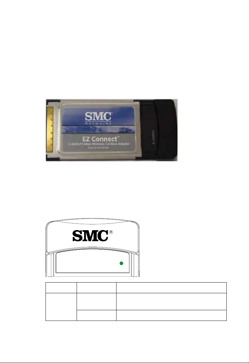
ESCRIZIONE HARDWARE
La scheda Cardbus wireless EZ Connect™ fornisce connessioni
a 11 Mbps. È pienamente conforme alle specifiche dello standard
IEEE 802.11b. La scheda può essere installata su qualsiasi
notebook dotato di uno slot CardBus tipo II o tipo III.
Indicatore LED
La scheda Cardbus wireless EZ Connect™ presenta un indicatore
di stato LED , come illustrato nella figura e nella tabella riportate di
seguito.
Link/Act
LED Stato Descrizione
Link/Act
(Coll./Att)
Acceso
(verde)
Lampeggiante
La scheda è associata alla LAN wireless.
La scheda sta trasmettendo/ricevendo dati.
5
Page 10

I
NSTALLAZIONE
DRIVER E UTILITY
DI
Il CD di installazione incluso nella confezione contiene
tutti i software disponibili per la scheda Cardbus wireless
EZ Connect™. Tutti i driver nuovi o aggiornati possono
essere scaricati dal sito Web di SMC all'indirizzo Internet:
www.smc.com
È possibile che le informazioni fornite in questa sezione
non corrispondano perfettamente alla versione di Windows
in uso. Infatti i passaggi e le schermate di esempio riportati
sono stati creati con Windows XP. Windows 98SE, Windows
Millennium Edition e Windows 2000 sono simili, ma non
identici a Windows XP
Note: 1. Per gli utenti di Windows 98, i processi di installazione
o www.smc-europe.com.
.
potrebbero richiedere l'utilizzo della copia originale del
sistema operativo Windows. Tenere il CD del sistema
operativo Windows a portata di mano prima di procedere
all'installazione.
2. Prima di inserire la scheda nel laptop, si consiglia di
installare innanzitutto il software dell'utility e del driver.
7
Page 11
INSTALLAZIONE DI DRIVER E UTILITY
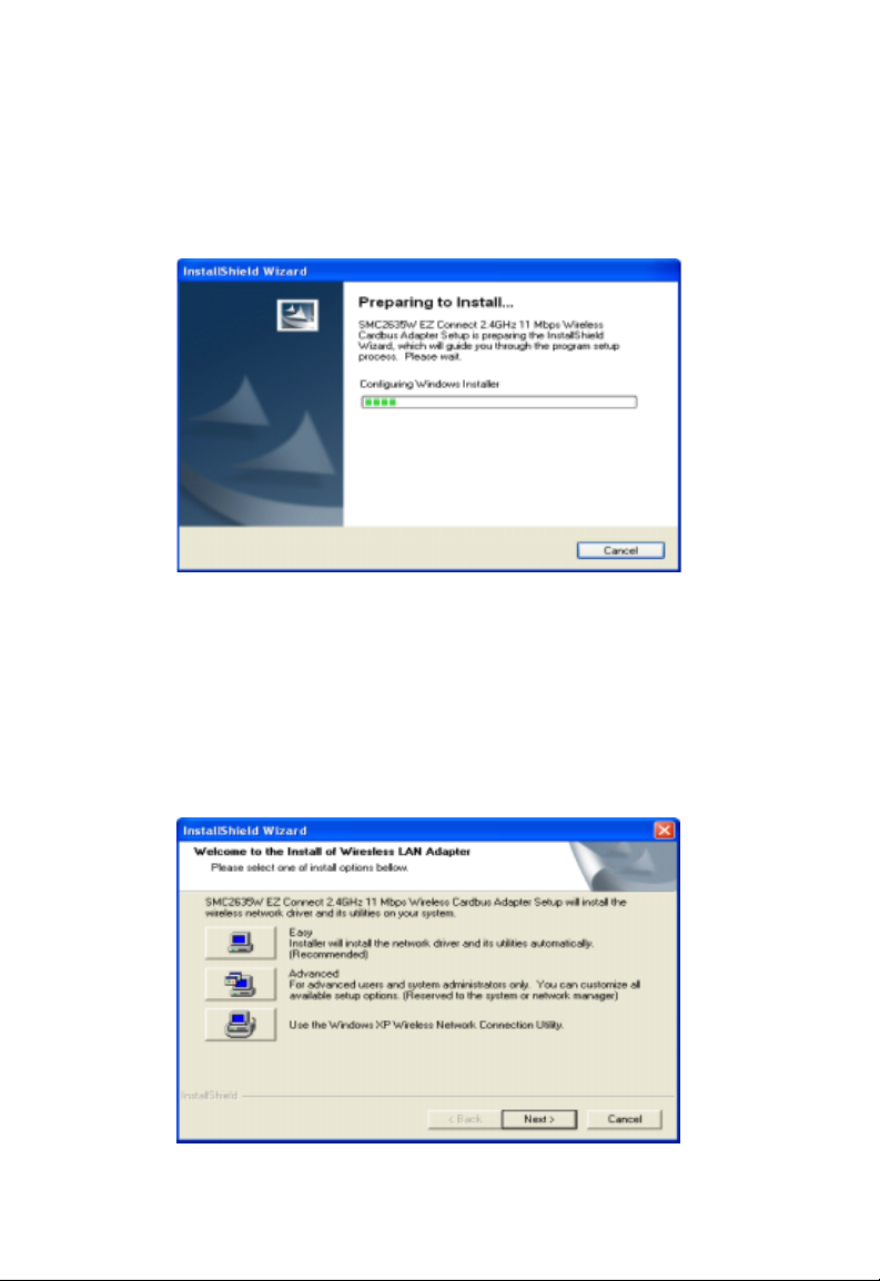
1. Inserire il CD nell'unità CD-ROM. Il programma si avvierà
automaticamente. La finestra [InstallShield Wizard] (Installazione
guidata InstallShield) verrà visualizzata automaticamente.
2. Per l'installazione del software sono disponibili tre opzioni.
Selezionare [Easy] (Semplice) per l'installazione facile. Per
gli utenti che desiderano utilizzare la Configurazione Wireless
Zero di Windows XP per la gestione della sched, selezionare
l'opzione [Use the Windows XP Wireless Network Connection
Utility] (Utilizza l'utility di connessione alla rete wireless di
Windows XP).
8
Page 12
INSTALLAZIONE DI DRIVER E UTILITY
3.
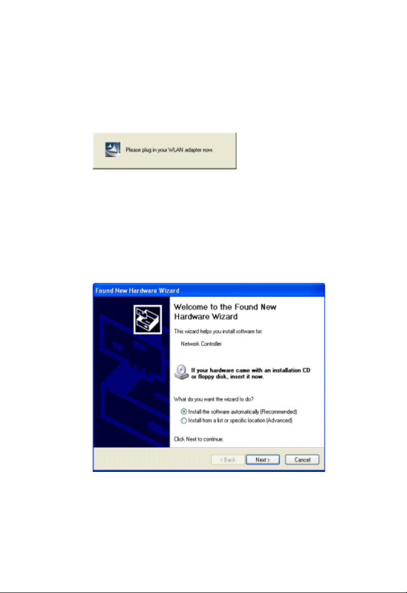
Il sistema avvierà l'installazione dei file. Il processo potrebbe
richiedere alcuni minuti. A questo punto verrà visualizzato
questo messaggio con la richiesta di inserire la scheda nel
laptop.
4. Il sistema rileverà automaticamente la scheda al suo
inserimento nel laptop. Dopo di che verrà visualizzata
la finestra [Found New Hardware Wizard] (Installazione
guidata nuovo hardware). Selezionare [Install the
software automatically (Recommended)] (Installa il
software automaticamente (scelta consigliata)) e fare
clic su [Next] (Avanti).
9
Page 13
INSTALLAZIONE DI DRIVER E UTILITY
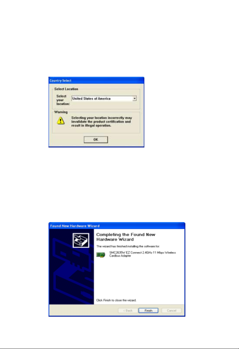
5.
Per gli utenti che utilizzano questa scheda fuori dagli Stati
Uniti
o dal Canada, sarà visualizzata la finestra [Country
Select] (Selezione Paese). Selezionare il Paese in cui si
utilizza la scheda.
Nota: Questa configurazione di dominio riguarda solo gli
utenti fuori dal dominio regolatore FCC. Se si utilizza
questa scheda negli Stati Uniti o in Canada, saltare
questo passaggio.
6. Sarà quindi visualizzata questa finestra che indica l'avvenuta
installazione del driver nel sistema. Fare clic su [Finish] (Fine)
per completare l'installazione. A questo punto la scheda è
pronta per l'uso.
10
Page 14

INSTALLAZIONE HARDWARE
Le schede di rete sono sensibili all'elettricità statica.
Per proteggere la scheda, evitare il contatto con i connettori
e toccare spesso la messa a terra per equalizzare le cariche
statiche prima di maneggiarla. Per inserire la scheda:
1. Individuare uno slot CardBus tipo II o tipo III disponibile
sul laptop.
2. Con il connettore CardBus a 68 pin della scheda rivolto
verso lo slot Cardbus e l'etichetta [EZ Connect™ Wireless
Cardbus Adapter] (Scheda Cardbus wireless EZ Connect™)
rivolta verso l'alto, introdurre la scheda nello slot come
illustrato di seguito.
Nota:
Prima di inserire la scheda nel laptop, installare
il software
dell'utility e del driver.
11
Page 15

C
ONFIGURAZIONE DELL'UTILITY
Gestione scheda wireless SMC
Per comunicare con altre periferiche 802.11b o 802.11g,
è necessario configurare innanzitutto la scheda SMC2635W.
Fare doppio clic sull'icona presente sul desktop per avviare
l'utility di configurazione. In alternativa è anche possibile
accedervi dal menu [Start].
Le schermate di esempio sono state create con Windows XP
e non saranno esattamente uguali in tutti i sistemi operativi.
Tuttavia le funzioni sono identiche.
L'utility di configurazione include le 5 schede seguenti:
[Configuration] (Configurazione)
Questa scheda consente di impostare i parametri della scheda.
[Link Information] (Informazioni sul collegamento)
Questa scheda consente di visualizzare lo stato della rete.
[IP Information] (Informazioni IP)
Questa scheda visualizza i dati TCP/IP.
[Site Survey] (Verifica sito)
Questa scheda ricerca/visualizza tutte le periferiche wireless
all'interno della portata del segnale della scheda.
[Version information] (Informazioni sulla versione)
Questa scheda mostra le informazioni sulla versione di driver e utility
13
.
Page 16

GESTIONE SCHEDA WIRELESS SMC
Nella parte inferiore di ciascuna schermata si trovano due caselle
che è possibile selezionare:
• [Radio On/Radio Off] (Radio accesa/spenta)
Questa casella consente di attivare/disattivare la trasmissione/
ricezione della scheda.
•[Help] (Guida)
Fare clic su questa casella per visualizzare il file della Guida.
Configuration (Configurazione)
Andare alla scheda [Configuration] (Configurazione) per impostare
i parametri della scheda SMC2635W.
[Select Profile:] (Seleziona profilo)
È possibile specificare un nome di profilo per una configurazione
di parametri specifica.
[New] (Nuovo)
Per configurare un nuovo profilo, fare clic su [New] (Nuovo).
14
Page 17

CONFIGURAZIONE DELL'UTILITY
[Save] (Salva)
Per salvare un nuovo profilo dopo averne configurato
le impostazioni, fare clic su [Save] (Salva).
[Delete] (Elimina)
Per eliminare un profilo, selezionare il profilo dal menu
a discesa nel campo [Select Profile] (Seleziona profilo),
quindi fare clic su [Delete] (Elimina).
[SSID:]
Immettere un SSID per la rete wireless a cui si desidera
eseguire il collegamento. Per eseguire il roaming tra più access
point, impostare il [SSID:] su [ANY] (Qualsiasi) per consentire
il collegamento a qualunque access point presente all'interno
della portata del segnale.
[Channel:] (Canale)
Se si sta configurando una rete wireless ad hoc, impostare
il numero del canale sullo stesso canale radio utilizzato dagli
altri client wireless del gruppo. Tuttavia, se si sta effettuando
un collegamento a una rete attraverso un access point, il canale
verrà automaticamente impostato sul canale utilizzato dall'access
point. (Vedere la sezione "Topologie della rete" a pagina 25.)
È necessario impostare manualmente il canale solo quando
l'opzione [Operating Mode:] (Modalità di esecuzione) è
[802.11 AdHoc].
Nota: Le impostazioni dei canali disponibili sono regolamentate
dalle normative locali che determinano il numero di canali
disponibili.
[Transmit Rate:] (Velocità di trasmissione)
Questo campo indica la velocità di trasmissione dei dati.
Selezionare la velocità di trasmissione appropriata.
Velocità
(Impostazione predefinita: [Auto] (Automatico).)
più basse consentono un miglior raggio d'azione.
15
Page 18

GESTIONE SCHEDA WIRELESS SMC
[Operating Mode:] (Modalità di esecuzione)
Impostare la modalità di esecuzione della scheda su [802.11
AdHoc] per un ambiente di rete che non presenta access point,
o su [Infrastructure] (Infrastruttura) per le connessioni con un
access point
[Tx Power] (Potenza Tr)
Spostare il dispositivo di scorrimento verso l'alto o verso il basso
all'interno del campo [Tx Power] (Potenza Tr) per aumentare o
diminuire la potenza di trasmissione.
[Encryption:] (Crittografia)
Per abilitare la funzione WEP (Wired Equivalent Privacy),
impostare questa opzione su [128-bit] o [64-bit].
La WEP implementata nella scheda Cardbus wireless
EZ Connect™ di SMC si basa sull'algoritmo di crittografia RC4.
Le chiavi di crittografia fornite garantiscono la riservatezza dei
dati. La protezione WEP protegge la LAN wireless contro gli
accessi non autorizzati e lo spionaggio da parte di intrusi. Se si
utilizza WEP, tutti i client sulla stessa rete devono utilizzare le
stesse impostazioni della chiave WEP per comunicare tra loro.
[Key Type:] (Tipo chiave)
Selzionare [Hex] (Esadecimale) o [ASCII].
[Default Key:] (Chiave predefinita)
Scegliere una chiave per la crittografia.
[Passphrase:] (Frase password)
Selezionare questa casella per generare automaticamente le
chiavi per la crittografia. Innanzitutto selezionare questa casella,
quindi inserire una stringa di caratteri nello spazio. Le chiavi di
codifica saranno create automaticamente. Quando la crittografia
è impostata su [128-bit], sarà creata solo la chiave [Key 1]
(Chiave 1).
16
Page 19

CONFIGURAZIONE DELL'UTILITY
Se la crittografia è impostata su [64-bit], saranno create
quattro chiavi. Ricordarsi di utilizzare le stesse impostazioni
per [Passphrase:] (Frase password) e [Def ault Key:] (Chiave
predefinita) su tutti gli altri client presenti nella rete.
Nota: Una stringa frase password può essere composta
da un massimo di 32 caratteri alfanumerici.
Impostazione della WEP
Impostazione automatica
Per configurare la funzione WEP, attenersi alla seguente
procedura:
1. Selezionare [128-bit] o [64-bit] nel campo [Encryption:]
(Crittografia).
Per creare automaticamente le chiavi, selezionare la casella
2.
[Passphrase:] (Frase password) e digitare una stringa di
caratteri in questo campo.
3. Nel campo [Default Key:] (Chiave predefinita) selezionare
una chiave predefinita da utilizzare per la crittografia.
Fare clic su [Apply changes] (Applica modifiche) per rendere
4.
effettive le modifiche.
17
Page 20

GESTIONE SCHEDA WIRELESS SMC
Impostazione manuale
1. Selezionare [128-bit] o [64-bit] nel campo [Encryption:]
(Crittografia).
2. Nel campo [Key Type:] (Tipo chiave:) selezionare [ASCII]
o [Hex] (Esadecimale).
3. Nel campo [Default Key:] (Chiave predefinita:) selezionare
una chiave predefinita da utilizzare per la crittografia.
4. Digitare manualmente una stringa di caratteri nel campo del
numero di chiave corrispondente selezionato nel passaggio 3.
5. Fare clic su [Apply changes] (Applica modifiche) per rendere
effettive le modifiche.
Nota: Impostando la WEP senza utilizzare la funzione
[Passphrase:] (Frase password), se il campo [Key Type:]
(Tipo chiave) è impostato su [Hex] (Esadecimale) è
possibile utilizzare solo caratteri esadecimali (intervallo:
0~9 e A~F). Quando l'opzione [Encryption:] (Crittografia)
è impostata su [64-bit], è possibile immettere un massimo
di 10 caratteri esadecimali nel campo della chiave. Quando
l'opzione [Encryption:] (Crittografia) è impostata su
[128-bit], è possibile utilizzare un massimo di 26 caratteri
esadecimali. Se [Key Type:] (Tipo chiave) è impostato su
[ASCII] e [Encryption:] (Crittografia) su [64-bit], è possibile
immettere 5 caratteri ASCII nel campo della chiave. Per
la crittografia a 128 bit, è possibile utilizzare 13 caratteri
ASCII.
18
Page 21

CONFIGURAZIONE DELL'UTILITY
Link Information (Informazioni sul collegamento)
La schermata [Link information] (Informazioni sul collegamento)
visualizza le informazioni relative all'access point wireless a cui
si è correntemente collegati.
[Associated BSS ID:] (ID BSS associato)
Corrisponde all'indirizzo MAC dell'access point al quale è collegata
la scheda Cardbus in una rete infrastruttura. In una rete ad hoc,
l'ID BSS è un numero casuale generato dalla prima stazione che
comunica con altre stazioni presenti nella rete. L'ID BSS delle altre
stazioni sarà quindi impostato sullo stesso valore.
[Channel] (Canale)
Indica il canale utilizzato per il collegamento alla periferica wireless.
[Current Tx Rate] (Velocità Tr corrente)
Indica la velocità di trasmissione dei dati.
19
Page 22

GESTIONE SCHEDA WIRELESS SMC
[SSID]
Indica l'SSID (service set identification) dell'access point
al quale è collegata la scheda Cardbus.
[Rx Fragments] (Frammenti Ri)
Indica il numero dei messaggi o dei relativi frammenti ricevuti.
La velocità di progressione di questo contatore fornisce
un'indicazione generale del livello di attività.
[Tx Fragments] (Frammenti Tr)
Indica il numero dei messaggi o dei relativi frammenti trasmessi
dalla scheda. La velocità di progressione di questo contatore
fornisce un'indicazione generale del livello di attività.
[Link Quality:] (Qualità del collegamento)
Questo campo indica la qualità del collegamento della
connessione wireless.
[Signal Strength:] (Intensità del segnale)
Questo campo mostra l'intensità della connessione tra
la scheda e l'access point.
IP Information (Informazioni IP)
Questa schermata visualizza le informazioni IP del laptop.
A questo punto, dopo aver configurato la scheda Cardbus
wireless per il collegamento alle reti wireless, è necessario che
la scheda ottenga nuove impostazioni di rete. Rilasciando tutte
le precedenti impostazioni IP e rinnovandole con le impostazioni
dell'access point, è anche possibile verificare che la scheda sia
stata configurata correttamente. Per rilasciare le impostazioni IP
correnti, fare clic su [Release] (Rilascia), quindi su [Renew]
(Rinnova) per ottenere nuove impostazioni IP.
20
Page 23

CONFIGURAZIONE DELL'UTILITY
[IP Address:] (Indirizzo IP)
Questo campo visualizza l'indirizzo Internet del laptop.
[Subnet]
Questo campo visualizza una maschera utilizzata per
determinare la subnet al quale appartiene un indirizzo IP.
[Host Name:] (Nome host)
Questo campo visualizza il nome del computer sulla rete.
[Gateway:]
Questo campo visualizza l'indirizzo IP del gateway di rete.
21
Page 24

GESTIONE SCHEDA WIRELESS SMC
Site Survey (Verifica sito)
[Site Survey] analizza e visualizza tutte le periferiche wireless
nell'area. È possibile scegliere uno di essi ai cui effettuare il
collegamento facendo doppio clic su una voce.
[SSID]
È il Service Set ID (vedere "Configuration (Configurazione)"
a pagina 14 per ulteriori informazioni).
[BSSID]
È il Basic Service Set ID (vedere "Link Information (Informazioni
sul collegamento)" a pagina 19
[Channel] (Canale)
Indica il canale radio su cui funziona l'access point. (Vedere
"Link Information (Informazioni sul collegamento)" a pagina 19
per ulteriori informazioni).
per ulteriori informazioni).
22
Page 25

CONFIGURAZIONE DELL'UTILITY
[Encryption] (Crittografia)
L'icona di una chiave indica che la crittografia WEP
è stata abilitata.
[Signal] (Segnale)
Indica l'intensità del segnale dalla scheda alle periferiche
wireless elencate.
[Network Type] (Tipo di rete)
Questo campo indica la modalità di esecuzione delle periferiche
wireless elencate.
Version Information (Informazioni sulla versione)
Questa schermata mostra le informazioni sulla versione corrente
del driver e dell'utility. È possibile scaricare il firmware più recente
dal sito Web SMC all'indirizzo www.smc.com
.
23
Page 26

C
ONFIGURAZIONE E
PIANIFICAZIONE
La soluzione wireless EZ Connect di SMC supporta una
configurazione di rete wireless autonoma e una configurazione
integrata con LAN Ethernet.
SMC2635W può essere configurata come:
• Ad Hoc: per i piccoli gruppi che comunicano tra di loro,
senza access point.
• Infrastruttura: per le LAN wireless.
DELLA RETE
Topologie della rete
LAN wireless Ad Hoc
Una LAN wireless Ad Hoc
è composta da un gruppo
di computer, ciascuno dotato
di una scheda wireless,
collegato attraverso segnali
radio come una LAN
wireless indipendente.
Pertanto, i computer in
una specifica LAN wireless
Ad Hoc devono essere
configurati sullo stesso
canale radio. Una LAN wireless Ad Hoc può essere utilizzata
in un SOHO o un ambiente temporaneo.
PC con scheda
PCI wireless
LAN wireless ad hoc
Notebook con
scheda USB wireless
Notebook con
PC Card wireless
25
Page 27

TOPOLOGIE DELLA RETE
LAN wireless infrastruttura
Gli access point SMC (S802.11b/11g) consentono di fornire l'accesso
a una LAN cablata anche alle workstation wireless. Una LAN
integrata cablata e wireless è definita configurazione a infrastruttura.
Un BSS (Basic Service Set) è composto da un gruppo di utenti PC
wireless e un access point direttamente collegato alla LAN cablata.
Ogni PC wireless in questo BSS può comunicare con qualsiasi
computer nel gruppo wireless attraverso un collegamento radio o
accedere agli altri computer o alle risorse di rete nell'infrastruttura
LAN cablata attraverso l'access point.
La configurazione a infrastruttura non solo estende le capacità
di accesso dei PC wireless alla LAN cablata, ma estende inoltre
l'area effettiva di trasmissione per i PC wireless trasmettendo il
loro segnale attraverso uno o più access point.
È possibile utilizzare un'infrastruttura wireless per accedere a un
database centrale o per effettuare un collegamento tra lavoratori
mobili, come illustrato nella seguente figura.
Estensione di una LAN
cablata a schede wireless
Server
di file
PC desktop
Switch
Access point
PC con scheda
PCI wireless
Notebook con scheda
PC Card wireless
26
Page 28

CONFIGURAZIONE E PIANIFICAZIONE DELLA RETE
Impostazione del dominio di comunicazione
PC wireless fissi
Il BSS (Basic Service Set) è il dominio di comunicazione per
ciascun access point. Per i PC wireless che non necessitano
del supporto roaming, impostare l'SSID, l'ID di dominio per la
scheda wireless sull'SSID dell'access point a cui si desidera
eseguire il collegamento. Controllare con l'amministratore l'SSID
dell'access point al quale si sta eseguendo il collegamento.
PC Wireless in roaming
Un'infrastruttura wireless consente anche di supportare il
roaming per i lavoratori mobili. È possibile configurare più access
point per creare un ESS (Extended Service Set). Posizionando gli
access point in modo che venga creata un'area di copertura senza
interruzioni, gli utenti wireless all'interno di questo ESS possono
effettuare il roaming liberamente.
È possibile configurare il client wireless a una rete wireless
specifica o alla prima rete wireless disponibile.
Se si configura il client perché si connetta a una rete wireless
•
specifica, il client stabilisce una connessione radio all'AP
presente all'interno della rete wireless specificata che fonisce
la migliore qualità di comunicazione. Gli AP presenti in un'altra
rete wireless vengono ignorati.
• Se si configura il client perché si connetta alla prima rete
wireless disponibile (ossia con l'SSID impostato su [ANY]
(Qualsiasi)) il client stabilisce una connessione radio all'AP
che fornisce la migliore qualità di comunicazione. È bene
prestare attenzione poiché in presenza di più reti wireless,
27
Page 29

IMPOSTAZIONE DEL DOMINIO DI COMUNICAZIONE
il client potrebbe non riuscire a collegarsi a un AP che non
si trovi all'interno della rete alla quale si desidera eseguire
il collegamento.
• In una qualsiasi di queste configurazioni, il client eseguirà
la corrispondenza con il canale radio utilizzato dall'AP.
Server
di file
PC desktop
Area di copertura
cellula wireless
Switch
Notebook con scheda
PC Card wireless
<BSS1>
PC con scheda
PCI wireless
Notebook con schede
PC Card wireless
Access point
<ESS>
Roaming senza problemi
Access point
PC con scheda
PCI wireless
Prima di impostare un ESS per il roaming, è necessario scegliere
un canale radio libero e una posizione adatta per gli access point
in modo da ottimizzare le prestazioni (vedere "Risoluzione dei
problemi" a pagina 29 per maggiori informazioni su installazione
e utilizzo).
28
<BSS2>
Page 30

RISOLUZIONE DEI PROBLEMI
Effettuare i seguenti controlli per la risoluzione dei problemi prima
di contattare l'assistenza tecnica di SMC.
Problemi di installazione della scheda
Se il computer non rileva la scheda Cardbus EZ Connect™
o i driver della rete non sono stati installati correttamente,
eseguire i seguenti controlli:
• Accertarsi che la scheda sia posizionata correttamente nello
slot Cardbus. Quando si inserisce la scheda wireless nello slot
del notebook, viene emesso un bip se la scheda è inserita
correttamente. Controllare se sussistono problemi hardware,
ad esempio danni fisici al connettore della scheda.
• Provare la scheda in un altro slot Cardbus . Se anche in questo
caso si verifica un errore, provare sul computer un'altr a scheda
Cardbus wireless SMC2635W il cui corretto funzionamento
sia già stato accertato.
• Assicurarsi che il computer utilizzi il BIOS più recente.
• Se sul computer sono presenti altre schede di rete, è possibile
che si sia verificato un conflitto. Rimuo vere tutte le schede dal
computer e provare ciascuna scheda wireless separatamente.
• Se si verificano ancora problemi, estrarre la scheda wireless.
Eliminare i programmi di driver e utility. Quindi, andare su
[Control Panel] (Pannello di controllo) ed eliminare la scheda
dal menu di configurazione della rete. Riavviare il notebook
e installare nuovamente la scheda, il driver e l'utility.
29
Page 31

PROBLEMI DI CONNESSIONE DI RETE
Problemi di connessione di rete
Se il LED relativo al collegamento presente sulla scheda non
si illumina o se non è possibile accedere alle risorse di rete dal
computer, controllare quanto segue:
• Accertarsi che siano installati i driver del software adatti al
sistema operativo . Se necessario, prov are a reinstallare i driver .
• Accertarsi che il computer e tutte le altre periferiche di rete
siano alimentate correttamente.
• L'access point a cui si desidera effettuare il collegamento
potrebbe essere difettoso. Provare ad utilizzare un altro
access point.
Se non è possibile accedere a un servizio Windows o NetWare
•
sulla rete, controllare di aver abilitato e configurato il servizio
correttamente. Se non è possibile collegarsi a un particolare
server, accertarsi di disporre dei diritti di accesso e di un ID
e una password validi.
• Se non è possibile accedere a Internet, accertarsi di aver
configurato il sistema per il protocollo TCP/IP.
Se la stazione wireless non è in grado di comunicare con un
computer nella LAN Ethernet quando è configurata in modalità
infrastruttura, controllare quanto segue:
• Accertarsi che l'access point a cui la stazione è associata
sia attivo.
•
Se il collegamento ancora non riesce, modificare l'impostazione
dell'access point e di tutte le stazioni all'interno del servizio
BSS su altro canale radio.
• Accertarsi che l'SSID sia lo stesso utilizzato dall'access point
per una stazione con il roaming disabilitato o che sia lo stesso
di quello utilizzato dagli access point nell'ESS (Extended
Service Set).
30
Page 32

RISOLUZIONE DEI PROBLEMI
Tabella distanze massime prodotti wireless 802.11b
Importante!
Le distanze massime indicate di seguito sono livelli soglia
effettivamente testati. Tuttavia, esistono molte variabili da
considerare, ad esempio la costruzione o la composizione di
una barriera, l'interferenza presente nell'ambiente locale che
può avere un impatto sulle distanze, abbassando notevolmente
i relativi livelli soglia, rispetto a quelli indicati. Per domande o
commenti sulle funzioni o sulle prestazioni di questo prodotto,
o se si desiderano informazioni sulla linea completa dei nostri
prodotti wireless, vistare il sito Web www.smc.com
prodotto venduto la SMC Networks offre una garanzia di
soddisfazione di 30
di vita del prodotto.
Tabella distanza massima schede Cardbus wireless 802.11b
Condizioni ambientali 11 Mbps 5,5 Mbps 2 Mbps 1 Mbps
giorni e una garanzia limitata per la durata
Gamma di velocità e distanze
. Per ogni
All'esterno:
nel raggio visivo senza
interferenze né ostruzioni
tra access point e client.
All'interno: Un tipico
ambiente d’ufficio o
domestico con ostruzioni
dal pavimento al soffitto
tra access point e client.
Un ambiente
160 m 195 m 255 m 350 m
72 m 73 m 73 m 75 m
31
Page 33

TECHNICAL SPECIFICATIONS
General Specifications
Functional Criteria
Data Rate
1, 2, 5.5, 11 Mbps
Network Connection
IEEE 802.11b
Operating Range
Up to 350 m at 1 Mbps
Up to 160 m at 11 Mbps
Radio Signal
Signal Type
Direct Sequence Spread-Spectrum (DSSS)
Operating Channel and Frequency
USA - FCC: 11 channels, 2412~2462 MHz
Canada - IC: 11 channels, 2412~2462 MHz
Europe - ETSI: 13 channels, 2412~2472 MHz
France: 4 channels, 2457~2472 MHz
Sensitivity
-80 dBm (typical)
Modulation
CCK, BPSK, QPSK
Output Power
>16 dBm
33
Page 34

SOFTWARE DRIVERS
Physical Characteristics
Power Consumption
3.3 V, TX: 240 mA, RX: 160 mA
Dimensions
12.8 x 5.3 cm
Antenna
Built-in antenna
LED Indicator
Link/Act
Host Interface
32-bit Cardbus
Standards Conformance
Wireless Standard: IEEE 802.11b
Environmental
Temperature Operating: 0 to 55 °C
Storage: 0 to 70 °C
Humidity: 5 to 40% (noncondensing)
Vibration/Shock/Drop: IEC 68-2-34, IEC 68-2-27, IEC68-2-32
Certification
CE Mark, EN50081-1, EN55022 Class B
EN50082-1, IEC 61000-4-2/3/4/6/11, IEC 60601-1-2
Emissions, FCC Part 15 Class B, ETS 300-328, VCCI
EN60950
UL1950/CSA22.2 No.950
IEC 60601-1
Software Drivers
Windows 98SE
Windows Me
Windows 2000
Windows XP
34
Page 35

COMPLIANCES
Federal Communication Commission Interference
Statement
This equipment has been tested and found to comply with the limits for
a Class B digital device, pursuant to Part 15 of the FCC Rules. These limits
are designed to provide reasonable protection against harmful interference
in a residential installation. This equipment generates, uses and can radiate
radio frequency energy and, if not installed and used in accordance with the
instructions, may cause harmful interference to radio communications.
However, there is no guarantee that interference will not occur in a particular
installation. If this equipment does cause harmful interference to radio or
television reception, which can be determined by turning the equipment off
and on, the user is encouraged to try to correct the interference by one of the
following measures:
• Reorient or relocate the receiving antenna
• Increase the separation between the equipment and receiver
• Connect the equipment into an outlet on a circuit different from that
to which the receiver is connected
• Consult the dealer or an experienced radio/TV technician for help
FCC Caution: Any changes or modifications not expressly approved by the
party responsible for compliance could void the user's authority to operate this
equipment. This device complies with Part 15 of the FCC Rules. Operation is
subject to the following two conditions: (1) This device may not cause harmful
interference, and (2) this device must accept any interference received,
including interference that may cause undesired operation.
IMPORTANT NOTE:
FCC Radiation Exposure Statement
This equipment complies with FCC radiation exposure limits set forth for an
uncontrolled environment. This equipment should be installed and operated
with a minimum distance of 20 centimeters (8 inches) between the radiator and
your body. This transmitter must not be co-located or operating in conjunction
with any other antenna or transmitter.
Wireless 2.4 GHz Band Statements:
As the SMC2635W Wireless Cardbus can operate in the 2412-2462 MHz
frequency band it is limited by the FCC, Industry Canada and some other
countries to indoor use only so as to reduce the potential for harmful
interference to co-channel Mobile Satellite systems.
The term “IC:” before the radio certification number only signifies that
Industry Canada technical specifications were met.
i
Page 36

COMPLIANCES
Industry Canada - Class B
This digital apparatus does not exceed the Class B limits for radio noise emissions
from digital apparatus as set out in the interference-causing equipment standard
entitled “Digital Apparatus” ICES-003 of Industry Canada.
Cet appareil numérique respecte les limites de bruits radioélectriques applicables
aux appareils numériques de Classe B prescrites dans la norme sur le matérial
brouilleur: « Appareils Numériques » NMB-003 édictée par l’Industrie.
Australia/New Zealand AS/NZS 4771
Contact SMC at:
SMC Networks, Inc.
38 Tesla
Irvine, CA 92618
Phone: (949) 679-8000
EC Conformance Declaration
The following importer/manufacturer is responsible for making this declaration:
SMC Networks Europe,
Edificio Conata II,
Calle Fructuós Gelabert 6-8, 2
08970 - Sant Joan Despí,
Barcelona, Spain.
This RF product complies with R&TTE Directive 99/5/EC. For the evaluation
of the compliance with this Directive, the following standards were applied:
• Electromagnetic compatibility and radio spectrum matters (ERM)
EN300 328-1 (2001-12)
EN300 328-2 (2001-12)
• Electromagnetic Compatibility (EMC) Standard for radio equipment
and services
EN301 489-1
EN301 489-17
• Safety Test
EN60950
o
, 4a,
ii
Page 37

C
OMPLIANCES
Countries of Operation & Conditions of Use in the European
Community
This device is intended to be operated in all countries of the European Community.
Requirements for indoor vs. outdoor operation, license requirements and allowed
channels of operation apply in some countries as described below:
Note: The user must use the configuration utility provided with this product to
ensure the channels of operation are in conformance with the spectrum
usage rules for European Community countries as described below.
• This device requires that the user or installer properly enter the current country
of operation in the command line interface as described in the user guide, before
operating this device.
• This device will automatically limit the allowable channels determined by the
current country of operation. Incorrectly entering the country of operation may
result in illegal operation and may cause harmful interference to other system.
The user is obligated to ensure the device is operating according to the channel
limitations, indoor/outdoor restrictions and license requirements for each
European Community country as described in this document.
• This device may be operated indoors or outdoors in all countries of the European
Community using the 2.4 GHz band: Channels 1 - 13, except where noted below.
- In Italy the end-user must apply for a license from the national spectrum
authority to operate this device outdoors.
- In Belgium outdoor operation is only permitted using the 2.46 - 2.4835 GHz
band: Channel 13.
- In France outdoor operation is only permitted using the 2.4 - 2.454 GHz band:
Channels 1 - 7.
Wichtige Sicherheitshinweise (Germany)
1. Bitte lesen Sie diese Hinweise sorgfältig durch.
2. Heben Sie diese Anleitung für den späteren Gebrauch auf.
3. Vor jedem Reinigen ist das Gerät vom Stromnetz zu trennen. Verwenden Sie
keine Flüssigoder Aerosolreiniger. Am besten eignet sich ein angefeuchtetes
Tuch zur Reinigung.
4. Die Netzanschlu ßsteckdose soll nahe dem Gerät angebracht und leicht
zugänglich sein.
5. Das Gerät ist vor Feuchtigkeit zu schützen.
6. Bei der Aufstellung des Gerätes ist auf sicheren Stand zu achten. Ein Kippen
oder Fallen könnte Beschädigungen hervorrufen.
7. Die Belüftungsöffnungen dienen der Luftzirkulation, die das Gerät vor
Überhitzung schützt. Sorgen Sie dafür, daß diese Öffnungen nicht abgedeckt
werden.
iii
Page 38

COMPLIANCES
8. Beachten Sie beim Anschluß an das Stromnetz die Anschlußwerte.
9. Verlegen Sie die Netzanschlußleitung so, daß niemand darüber fallen kann.
Es sollte auch nichts auf der Leitung abgestellt werden.
10.Alle Hinweise und Warnungen, die sich am Gerät befinden, sind zu beachten.
11.Wird das Gerät über einen längeren Zeitraum nicht benutzt, sollten Sie es vom
Stromnetz trennen. Somit wird im Falle einer Überspannung eine
Beschädigung vermieden.
12.Durch die Lüftungsöffnungen dürfen niemals Gegenstände oder Flüssigkeiten
in das Gerät gelangen. Dies könnte einen Brand bzw. elektrischen Schlag
auslösen.
13.Öffnen sie niemals das Gerät. Das Gerät darf aus Gründen der elektrischen
Sicherheit nur von authorisiertem Servicepersonal geöffnet werden.
14.Wenn folgende Situationen auftreten ist das Gerät vom Stromnetz zu trennen
und von einer qualifizierten Servicestelle zu überprüfen:
a. Netzkabel oder Netzstecker sind beschädigt.
b. Flüssigkeit ist in das Gerät eingedrungen.
c. Das Gerät war Feuchtigkeit ausgesetzt.
d. Wenn das Gerät nicht der Bedienungsanleitung entsprechend funktioniert
oder Sie mit Hilfe dieser Anleitung keine Verbesserung erzielen.
e. Das Gerät ist gefallen und/oder das Gehäuse ist beschädigt.
f. Wenn das Gerät deutliche Anzeichen eines Defektes aufweist.
15. Stellen Sie sicher, daß die Stromversorgung dieses Gerätes nach der EN
60950 geprüft ist. Ausgangswerte der Stromversorgung sollten die Werte
von AC 7,5-8V, 50-60Hz nicht über oder unterschreiten sowie den minimalen
Strom von 1A nicht unterschreiten.
Der arbeitsplatzbezogene Schalldruckpegel nach DIN 45 635 Teil 1000
beträgt 70dB(A) oder weniger.
iv
Page 39

LEGAL INFORMATION
AND
SMC's Limited Warranty Statement
SMC Networks Europe ("SMC") warrants its products to be free from defects
in workmanship and materials, under normal use and service, for the applicable
warranty term. All SMC products carry a standard 2 year limited warranty from
the date of purchase from SMC or its Authorized Reseller. SMC may, at its own
discretion, repair or replace any product not operating as warranted with a similar
or functionally equivalent product, during the applicable warranty term. SMC will
endeavour to repair or replace any product returned under warranty within 30 days
of receipt of the product. As new technologies emerge, older technologies become
obsolete and SMC will, at its discretion, replace an older product in its product line
with one that incorporates these newer technologies.
The standard limited warranty can be upgraded to a 5 year Limited Lifetime *
warranty by registering new products within 30 days of purchase from SMC
or its Authorized Reseller. Registration can be accomplished via the enclosed
product registration card or online via the SMC web site. Failure to register will
not affect the standard limited warranty. The Limited Lifetime warranty covers a
product during the Life of that Product, which is defined as a period of 5 years
from the date of purchase of the product from SMC or its authorized reseller.
All products that are replaced become the property of SMC. Replacement
products may be either new or reconditioned. Any replaced or repaired product
carries, either a 30-day limited warranty or the remainder of the initial warranty,
whichever is longer. SMC is not responsible for any custom software or firmware,
configuration information, or memory data of Customer contained in, stored on,
or integrated with any products returned to SMC pursuant to any warranty.
Products returned to SMC should have any customer-installed accessory or
add-on components, such as expansion modules, removed prior to returning
the product for replacement. SMC is not responsible for these items if they are
returned with the product.
Customers must contact SMC for a Return Material Authorization number prior to
returning any product to SMC. Proof of purchase may be required. Any product
returned to SMC without a valid Return Material Authorization (RMA) number
clearly marked on the outside of the package will be returned to customer at
customer's expense. Customers are responsible for all shipping charges from
their facility to SMC. SMC is responsible for return shipping charges from SMC
to customer.
CONTACTS
v
Page 40

Legal Information and Contacts
WARRANTIES EXCLUSIVE: IF A SMC PRODUCT DOES NOT OPERATE AS
WARRANTED ABOVE, CUSTOMER'S SOLE REMEDY SHALL BE REPAIR OR
REPLACEMENT OF THE PRODUCT IN QUESTION, AT SMC'S OPTION. THE
FOREGOING WARRANTIES AND REMEDIES ARE EXCLUSIVE AND ARE IN LIEU
OF ALL OTHER WARRANTIES OR CONDITIONS, EXPRESSED OR IMPLIED,
EITHER IN FACT OR BY OPERATION OF LAW, STATUTORY OR OTHERWISE,
INCLUDING WARRANTIES OR CONDITIONS OF MERCHANTABILITY
AND FITNESS FOR A PARTICULAR PURPOSE. SMC NEITHER ASSUMES
NOR AUTHORIZES ANY OTHER PERSON TO ASSUME FOR IT ANY OTHER
LIABILITY IN CONNECTION WITH THE SALE, INST ALLATION, MAINTENANCE
OR USE OF ITS PRODUCTS. SMC SHALL NOT BE LIABLE UNDER THIS
WARRANTY IF ITS TESTING AND EXAMINATION DISCLOSE THE ALLEGED
DEFECT IN THE PRODUCT DOES NOT EXIST OR WAS CAUSED BY
CUSTOMER'S OR ANY THIRD PERSON'S MISUSE, NEGLECT, IMPROPER
INSTALLATION OR TESTING, UNAUTHORIZED ATTEMPTS TO REPAIR,
OR ANY OTHER CAUSE BEYOND THE RANGE OF THE INTENDED USE,
OR BY ACCIDENT, FIRE, LIGHTNING, OR OTHER HAZARD.
LIMITATION OF LIABILITY: IN NO EVENT, WHETHER BASED IN
CONTRACT OR TORT (INCLUDING NEGLIGENCE), SHALL SMC BE LIABLE
FOR INCIDENTAL, CONSEQUENTIAL, INDIRECT, SPECIAL, OR PUNITIVE
DAMAGES OF ANY KIND, OR FOR LOSS OF REVENUE, LOSS OF BUSINESS,
OR OTHER FINANCIAL LOSS ARISING OUT OF OR IN CONNECTION WITH
THE SALE, INST ALLATION, MAINTENANCE, USE, PERFORMANCE, FAILURE,
OR INTERRUPTION OF ITS PRODUCTS, EVEN IF SMC OR ITS AUTHORIZED
RESELLER HAS BEEN ADVISED OF THE POSSIBILITY OF SUCH DAMAGES.
SOME COUNTRIES DO NOT ALLOW THE EXCLUSION OF IMPLIED
WARRANTIES OR THE LIMITATION OF INCIDENTAL OR CONSEQUENTIAL
DAMAGES FOR CONSUMER PRODUCTS, SO THE ABOVE LIMITATIONS
AND EXCLUSIONS MAY NOT APPLY TO YOU. THIS WARRANTY GIVES
YOU SPECIFIC LEGAL RIGHTS, WHICH MAY VARY FROM COUNTRY TO
COUNTRY. NOTHING IN THIS WARRANTY SHALL BE TAKEN TO AFFECT
YOUR STATUTORY RIGHTS.
* Under the limited lifetime warranty, internal and external power supplies, fans,
and cables are covered by a standard one-year warranty from date of purchase.
Full Installation Manual
Full installation manuals are provided on the Installation CD-Rom. Manuals
in other languages than those included on the CD-Rom are provided on
www.smc-europe.com
(section support).
vi
Page 41

Legal Information and Contacts
Firmware and Drivers
For latest driver, technical information and bug-fixes please visit
www.smc-europe.com
Contact SMC
Contact details for your relevant countries are available on www.smc-europe.com
and www.smc.com
Statement of Conditions
In line with our continued efforts to improve internal design, operational function,
and/or reliability, SMC reserves the right to make changes to the product(s)
described in this document without notice. SMC does not assume any liability
that may occur due to the use or application of the product(s) described herein.
In order to obtain the most accurate knowledge of installation, bug-fixes and other
product related information we advise to visit the relevant product support page
at www.smc-europe.com before you start installing the equipment. All information
is subject to change without notice.
Limitation of Liability
In no event, whether based in contract or tort (including negligence), shall SMC
be liable for incidental, consequential, indirect, special or punitive damages of an y
kind, or for loss of revenue, loss of business or other financial loss arising out of
or in connection with the sale, installation, maintenance, use, performance, f ailure
or interruption of its products, even if SMC or its authorized reseller has been
adviced of the possiblity of such damages.
(section support).
.
Copyright
Information furnished by SMC Networks, Inc. (SMC) is believed to be accurate
and reliable. However, no responsibility is assumed by SMC for its use, nor for
any infringements of patents or other rights of third parties which may result from
its use. No license is granted by implication or otherwise under any patent or
patent rights of SMC. SMC reserves the right to change specifications at any
time without notice.
Trademarks
SMC is a registered trademark and EZ Connect is a trademark of SMC Networks,
Inc. Other product and company names are trademarks or registered trademarks
of their respective holders.
vii
Page 42

 Loading...