

Page 1

Page 2

P N E U M A T I C T E C H N O L O G Y
Notes
Page 3

P N E U M A T I C T E C H N O L O G Y
Notes
Page 4

P N E U M A T I C T E C H N O L O G Y
Notes
Page 5

P N E U M A T I C T E C H N O L O G Y
1 INTRODUCTION 1
What can Pneumatics do? 1
Properties of Compressed Air 2
2 THE BASIC PNEUMATIC SYSTEM 3
The Air Production and distribution System 3
The Air Consumption System 4
3 COMPRESSED AIR THEORY 6
Units 6
Pressure 9
Properties of Gases 10
Isothermic change (Boyle’s Law) 10
Isobaric change 11
Charles Law 11
Law of Gay Lussac 11
Isochoric change 11
Adiabatic (Isentropic) change 12
Standard Volume 12
Flow 12
Bernoulli's Equation 12
Air Humidity 12
Relative humidity 14
Pressure and Flow 15
Use of the diagram: 16
Formulae: 17
Sonic Conductance 19
Indication of flow Characteristics 19
ISO 6358-1989, JIS B 8390-2000 19
Sonic conductance C 19
Critical Pressure Ratio B 19
Measuring sonic conductance C and critical pressure
ratio b 20
Formulas to calculating air flow rates Q 21
The standard flow Qn 22
Flow section S [mm2]: 23
4 AIR COMPRESSION AND DISTRIBUTION 24
Compressors 24
Reciprocating Compressors 24
Single stage Piston Compressor 24
Two stage Piston Compressor 25
Diaphragm compressor 25
Rotary compressors 26
Rotary sliding vane compressor 26
Screw compressor 26
Compressor rating 27
Volumetric Efficiency 27
Thermal and Overall Efficiency 27
Compressor Accessories 27
Air receiver 27
Sizing a receiver 28
Inlet filter 28
Air Dehydration 29
Aftercoolers 29
Air cooled 29
Water cooled 29
Air dryers 30
Absorption (deliquescent) Drying 30
Adsorption (desiccant) Drying 31
Refrigerant drying 32
Membrane Air Dryer 33
Water Removal Filter 33
Main line filter 34
Air Distribution 34
Dead End Line 35
Ring Main 35
Secondary Lines 36
Automatic Drains 36
Sizing Compressed Air Mains 37
Materials for Piping 40
Standard Gas Pipe (SGP) 40
Stainless steel pipes 40
Copper Tube 40
Rubber Tube (“Air Hose”) 41
Plastic tubing 41
Fittings in Systems 42
5 AIR TREATMENT 43
Filtering 43
Standard Filter 43
Pressure Regulation 47
Standard Regulator 47
Pilot Operated Regulator 49
Filter-Regulator 50
Characteristics 50
Sizing of Regulators and Filters 50
Compressed Air Lubrication 51
Proportional Lubricators 51
F.R.L. Units 53
Size and Installation 53
6 ACTUATORS 54
Linear Cylinders 54
Single Acting Cylinder 54
Double Acting Cylinder 54
Cylinder Construction 55
Cushioning 55
Special Cylinder Options 56
Double Rod 56
Non Rotating Rod 56
Twin Rod 56
Guided Cylinder 57
Slide Table 58
Flat Cylinder 58
Tandem Cylinder 58
Multi Position Cylinder 59
Cylinder Mounting 60
Floating Joints--- Rod Couplers 60
Column Strength 61
Cylinder Sizing 61
Cylinder Force 61
Theoretical Force 61
Required Force 63
Load Ratio 64
Speed Control 67
Air Flow and Consumption 67
Rotary Actuators 72
Rack and Pinion Type 72
Page 6

P N E U M A T I C T E C H N O L O G Y
Vane Type Rotary Actuators: 72
Sizing Rotary Actuators 72
Torque and Inertia 72
Special Actuators 75
Locking Cylinder 75
Rodless cylinders 75
With magnetic coupling, unguided 75
Guided types, with magnetic coupling 76
Guided, with mechanical coupling 76
Slide Units 77
Hollow Rod Cylinder 77
Linear Rotating Cylinder 78
Air Chuck (Gripper) 78
7 DIRECTIONAL CONTROL VALVES 79
Valve Functions 79
Symbol 79
Port Identification 80
Monostable and bi-stable 80
Valve Types 80
Poppet Valves 81
Sliding Valves 82
Spool Valves 82
Elastomer seal 82
Metal Seal 82
Plane Slide Valve 83
Rotary Valves 84
Valve Operation 84
Mechanical operation 84
Care when using Roller Levers 85
Manual Operation 85
Air Operation. 86
Piloted Operation. 87
Solenoid Operation 88
Direct Piping 89
Manifolds 89
Sub Bases 89
Multiple Sub Bases 90
Ganged Sub Bases 90
Valve Sizing 90
Indications for Flow capacity 90
Orifices in series connection 92
Flow capacity of tubes 93
Valves with Cylinders 94
Auxiliary Valves 97
Non-Return Valves 97
Speed Controllers 97
Shuttle Valve 97
Quick Exhaust Valves 98
8 BASIC CIRCUITS 99
Introduction 99
Elementary Functions 99
Flow Amplification 99
Signal Inversion 99
Selection 101
Memory Function 100
Time functions 101
Delayed switching on 102
Delayed switching off 102
Pulse on switching off 103
Pulse on releasing a valve 103
Cylinder Control 104
Manual Control 104
Single Acting Cylinder 104
Direct Operation and Speed Control 104
Interlock: AND Function 105
Inverse Operation: NOT Function 105
Double acting Cylinder 106
Direct Control 106
Holding the end positions 106
Detecting Cylinder Positions 107
Automatic Return 107
Repeating Strokes 109
Sequence Control 109
How to describe a sequence 109
Nomenclature 109
Sequence of two Cylinders 110
Single Cycle / Repeating Cycle 111
Opposing Commands 112
Elimination with a Pulse 112
Clamping: Pressure Control 112
Cascade System 113
Appendix 116
Symbols 116
Air Treatment Equipment 117
Actuators 118
Valves 118
JIS Valve Symbols 120
Circuits 121
Basic Rules 121
Rest Position 121
Circuit Layout 122
Nomenclature 123
Sample Diagrams 125
Fluid Power Formulas 126
Notes 134
Summary of Formulas & Equivalents 135
Notes 141
Afterword 146
Page 7

11 IINNTTRROODDUUCCTTIIOONN
A fluid power system is one that transmits and controls energy through the use of pressurized liquid or gas.
In Pneumatics, this media is air. This of course comes from the atmosphere and is reduced in volume by
compression, thus increasing its pressure. Compressed air is mainly used to do work by acting on a piston or vane
--- producing some useful motion for instance.
While many facets of industry use compressed air, the general field of Industrial Pneumatics will be considered
here.
The correct use of pneumatic control requires an adequate knowledge of pneumatic components and their
function to ensure their integration into an efficient working system. It is always the responsibility of the designer to
certify safety in all conditions --- including a failed condition. As with any other energy source, compressed air can
cause harm if not properly applied.
Although electronic control using a programmable sequencer or other logic controller may be currently
specified, it is still necessary to know the basic function of the pneumatic components.
This book deals with the technology of the components in control systems, describing types and design
features of air treatment equipment, actuators and valves, methods of interconnection and introduces basic
pneumatic circuits.
WHAT CAN P NEUM ATI CS DO?
The applications for compressed air are limitless, from the optician’s gentle use of low pressure air to test fluid
pressure in the human eyeball, the multiplicity of linear and rotary motions on robotic process machines, to the
high forces required for pneumatic presses and concrete breaking pneumatic drills.
The short list below serves only to indicate the versatility and variety of pneumatic control at work, in a
continuously expanding industry.
• Operation of system valves for air, water or chemicals
• Operation of heavy or hot doors
• Unloading of hoppers in building, steel making, mining and chemical industries
• Ramming and tamping in concrete and asphalt laying
• Lifting and moving in slab molding machines
• Crop spraying; crop seeding, and the operation of other agricultural equipment
• Spray painting and electrostatic powder coating
• Holding and moving in woodworking and furniture making
• Holding in jigs and fixtures in assembly machinery and machine tools
• Holding for gluing, heat sealing or welding plastics
• Holding for brazing or welding
• Metal-forming operations such as bending, drawing and flattening
• Spot welding machines
• Riveting
• Operation of guillotine blades
• Bottling and filling machines
• Wood working machinery drives and feeds
• Test rigs
• Machine tool, work or tool feeding
• Component and material conveyor transfer
• Pneumatic robots
Page 8

P N E U M A T I C T E C H N O L O G Y
• Auto gauging
• Air separation and vacuum lifting of thin sheets
• Dental drills
• And so much more… new applications are developed daily
PROPERT IES OF COMP RES SED AI R
Some important reasons for the wide use of compressed air in industry are:
Availability
Most factories and industrial plants have a compressed air supply in working areas, and portable
compressors can serve more remote situations.
Storage
It is easily stored in large volumes if required.
Simplicity of Design, Installation, and Control
Pneumatic components are of simple design and are easily fitted to provide extensive automated systems
with comparatively simple control.
Choice of Movement
Pneumatic components offer both linear movement and angular rotation with simple and continuously
variable operational speeds.
Economy
Installation is of relatively low cost due to modest component cost. There is also a low maintenance cost
due to long life without service. Pneumatic actuators do not produce heat --- other than the small amount
caused by internal friction, and do not consume energy unless motion occurs.
Reliability
Pneumatic components have a long working life resulting in high system reliability.
Resistance to Environment
Pneumatic systems are largely unaffected by high temperature, dusty, and corrosive atmospheres in which
other systems may fail.
Environmentally Clean
It is clean, and with proper exhaust air treatment, can be installed to clean room standards.
Safety
It is not a fire hazard in high-risk areas, and the system is unaffected by overload as actuators simply stall
or slip.
DO NOT COPY WITHOUT WRITTEN PERMISSION – 2 –
Page 9
P N E U M A T I C T E C H N O L O G Y
1
2 3
4
5
7
8
A
B
C
D
E
F
F
9
9
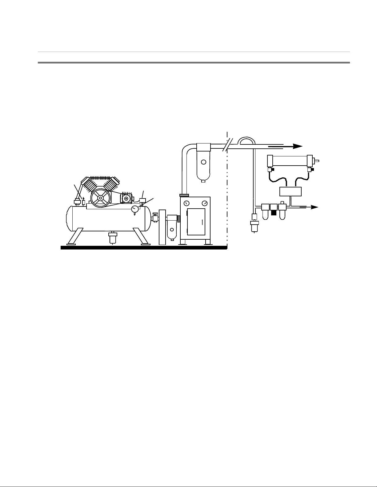
22 TTHHEE BBAASSIICC PPNNEEUUMMAATTIICC SSYYSSTTEEMM
Pneumatic cylinders, rotary actuators and air motors provide the force and movement of most pneumatic
control systems, to hold, move, form, and process material.
To operate and control these actuators, other pneumatic components are required i.e. air service units to
prepare the compressed air, and valves to control the pressure, flow and direction of movement of the actuators.
A basic pneumatic system, shown in Fig 2.1, consists of two main sections:
• The Air Production and Distribution System
• The Air Consumption System
Production
10
6
10
Consumption
Fig. 2.1 The Basic Pneumatic System
The component parts and their main functions are:
THE AIR P ROD UCTI ON AND DIS TRI BUTION S YSTE M
1. Compressor
Air taken in at atmospheric pressure is compressed and delivered at a higher pressure to the
pneumatic system. It thus transforms mechanical energy into pneumatic energy.
2. Electric Motor
Supplies the mechanical power to the compressor. It transforms electrical energy into mechanical
energy.
3. Pressure Switch
Controls the electric motor by sensing the pressure in the tank. It is set to a maximum pressure at
which it stops the motor, and a minimum pressure at which it restarts it.
4. Check Valve
Lets the compressed air from the compressor into the tank and prevents it leaking back when the
compressor is stopped.
DO NOT COPY WITHOUT WRITTEN PERMISSION – 3 –
Page 10

P N E U M A T I C T E C H N O L O G Y
5. Tank
Stores the compressed air. Its size is defined by the capacity of the compressor. The larger the
volume, the longer the interval between compressor runs. Most systems should be designed for a
50% duty cycle, providing at least 2x system demand in storage.
6. Pressure Gauge
Indicates the Tank Pressure.
7. Auto Drain
Drains all the water condensing in the tank without supervision.
8. Safety Valve
Blows compressed air off if the pressure in the tank should rise above the allowed pressure.
9. Refrigerated Air Dryer and After-cooler
Cools the compressed air to a few degrees above freezing point and condenses most of the air
humidity. This avoids having water in the downstream system. There should (for maximum efficiency)
be an aftercooler preceding the unit to start the cooling process or the refrigerated dryer will be overtaxed. Ideally, inlet air temp should be ambient or room temperature air.
10. Line Filters
Being located in the main pipe, the mainline filter must have a minimal pressure drop and the
capability of oil mist removal. It helps to keep the line free from particulate, water, and oil. A mainline
filter is typically used before the aftercooler and either a second mainline filter or a mist-separator is
installed inline as the compressed air leaves the production area. These filters are the primary
devices to insure clean, oil-free air.
THE AIR C ONS UMPT ION SYST EM
A. Air Take-off
For consumption, air is taken off from the top of the main pipe to allow occasional condensate to stay
in the main pipe. When it reaches a low point, a water take-off from beneath the pipe will flow into an
Automatic Drain and the condensate will be removed. Normally there would be a union in the pipe and
a shut-off valve to allow maintenance of the downstream components.
B. Auto Drain
Every descending tube should have a drain at its lowest point. The most efficient method
is an Auto Drain, which prevents water from remaining in the tube should manual draining
be neglected. Directly above the Auto Drain is an expansion chamber, allowing the air to
cool (through expansion) and remove more entrained liquid.
C. Air Service Unit
Traditionally known as an FRL, for filter, regulator, and lubricator. These components condition the
compressed air to provide clean air at optimum pressure, and (where required by component or
history --- most pneumatic devices are as a standard non-lube, meaning no additional lubricant is
required) add lubricant to extend the life of those pneumatic system components (e.g. air motors) that
need lubrication.
DO NOT COPY WITHOUT WRITTEN PERMISSION – 4 –
Page 11

P N E U M A T I C T E C H N O L O G Y
D. Directional Valve
Alternately pressurizes and exhausts the cylinder connections to control the direction of movement.
Shown as an individual device, there may be a number of directional valves grouped on a manifold.
E. Actuator
Transforms the potential energy of the compressed air into mechanical work. Shown is a linear
cylinder, it can also be a rotary actuator or an air tool etc.
F. Speed Controllers
Allow easy and step-less speed adjustment of the actuator movement.
We will discuss these components in more detail in sections 4 to 7, after a brief look at the theory of
compressed air. This is a must for understanding what happens in a pneumatic system.
DO NOT COPY WITHOUT WRITTEN PERMISSION – 5 –
Page 12

P N E U M A T I C T E C H N O L O G Y
J
n
33 CCOOMMPPRREESSSSEEDD AAIIRR TTHHEEOORRYY
UNIT S
For the practical application of pneumatics, it is necessary to appreciate the natural laws relating to the
behavior of air as a compressed gas and the physical dimensions in common use.
The International System of Units (the “Metric” system) has been in acceptance worldwide since 1960, but the
USA and UK still use the Imperial System to a great extent.
It is extremely important, in this ever shrinking world, that all measurement systems become clearly
understood. The definitive study of pneumatics on an international scale requires familiarity and competence with
either set of units; therefore this document will employ both English and SI units.
Quantity Symbol SI Unit Name Remarks
1 . B A S I C U N I T S :
Mass m Kg Kilogram
Length s m Meter
Time t s Second
Temperature, absolute T K Kelvin 0°C = 273.16 K
Temperature (Celsius)
t,
Radius r m Meter
Angle
Area, Section A,S m2 Square meter
Volume V m3 Cubic meter
Speed (velocity) v m s
Angular Speed
Acceleration a m s
Inertia
Force F N Newton
Weight G N Earth acceleration
Impulse
I
Work W J Joule = Newton meter = kg.m2 /s-2
Potential energy E, W J Joule
Kinetic energy E, W J Joule 0.5·m··v2
Torque M J Joule
Power P W Watt
3. RELATED TO COMPRESSED AIR
Pressure p Pa Pascal = N/m2
Standard volume Vn m
Volume flow Q m
Energy, Work E, W
Power P W Watt
Table 3.1 SI Units used in pneumatics
°C Degree Celsius
2. COMPOSED UNITS:
1 Radian (m/m)
-1
Meter per second
s-1 Radians per second
-2
Meter per sec. per sec.
Kgm2 Kilogram meter squared
= kg · m/s2
9.806 m/s2
Ns Newton Second
= J.s-1
3
Standard Cubic Meter
n
Normal Liter (Nl)
3
s-1 Std. cubic meters / sec
N.m
Joule
at
=760 mm Hg
Pa.m3 = N.m
p .Q = N.m·s-1 = W
= 0°C and p
DO NOT COPY WITHOUT WRITTEN PERMISSION – 6 –
Page 13

P N E U M A T I C T E C H N O L O G Y
n
n
To name units by powers of ten, smaller and larger than the above basic units, a number of prefixes have been
agreed upon and are listed below.
Power Prefix Symbol Power Prefix Symbol
10-1
10-2
10-3
10-6
deci d
centi c
milli m
micro µ
101
102
103
106
Deka da
Hecto h
Kilo k
Mega M
Table 3.2 Prefixes for powers of ten
This leads us to a km (kilo-meter or 1000 meters), a mm. (milli-meter or .001 meters) and a µ m (micro-meter
or a micron). Practice with these prefixes and pay attention to what the symbol represents in terms of powers of
ten. Pay special attention to the difference between M and m (for about a trillion reasons).
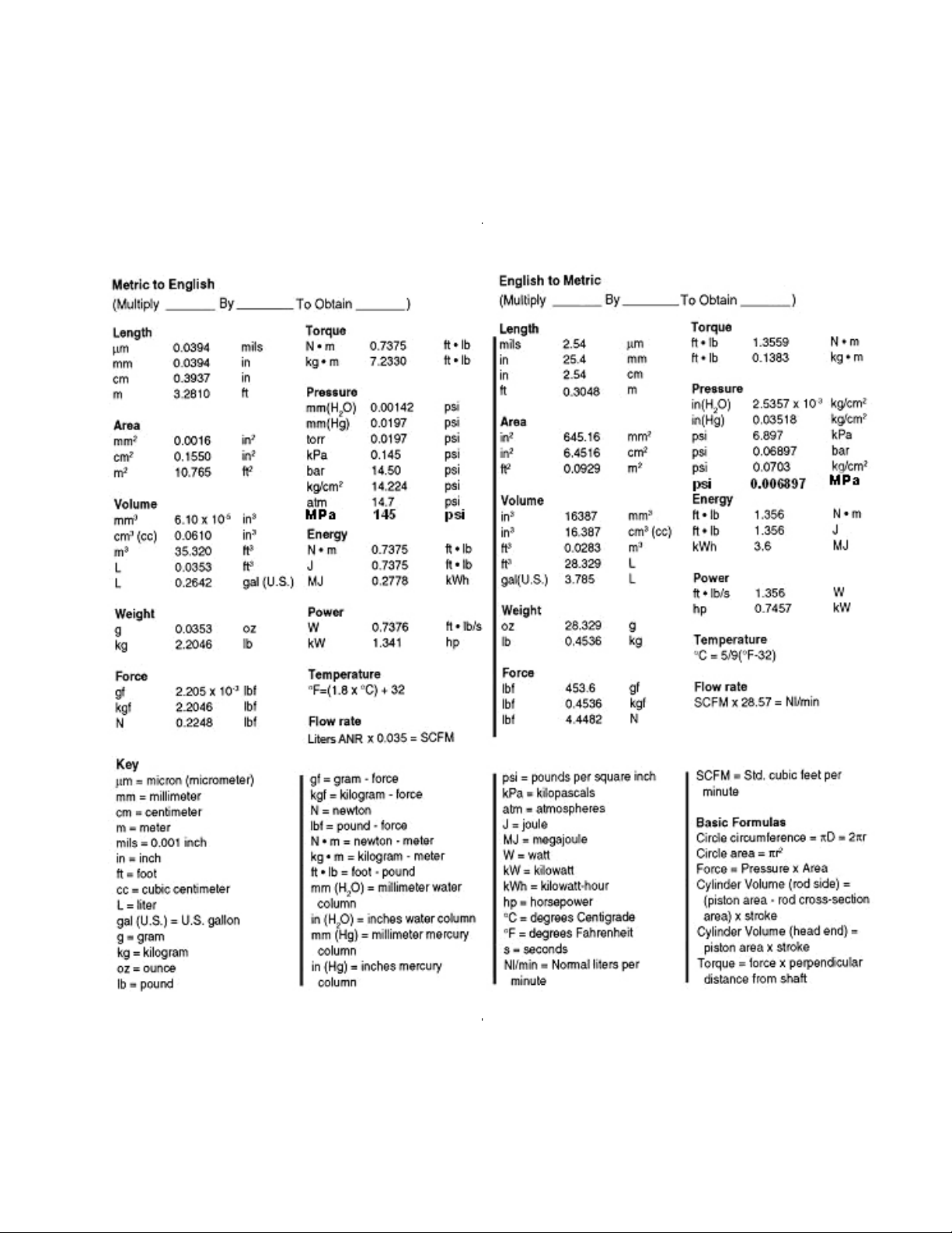
Converting from one standard of units to another is well documented. Converting is easiest when dealing with
an answer --- e.g. when dealing with a mathematical formula, use one standard only (for all terms) and then
convert the answer. Be aware that formulae may change when expressed in different units or standards.
The tables following show a comparison between the Metric SI units and the Imperial units.
Magnitude Metric Unit (m) English (e)
Factor m e Factor e m
Mass kg Pound 2.205 0.4535
g Ounce 0.03527 28.3527
Length m Foot 3.281 0.3048
m Yard 1.094 0.914
mm Inch 0.03937 25.4
Temperature °C °F 1.8°C+32 (°F-32)/1.8
Area, Section m2 Sq. ft. 10.76 0.0929
cm2 Sq. inch 0.155 6.4516
Volume m3 Cu. yard 1.308 0.7645
m
Volume Flow m
dm
3
dm3
3
/min scfm 35.31 0.02832
3
/min (l/min) scfm 0.03531 28.32
Cu. inch
Cu. ft.
0.06102
0.03531
16.388
28.32
Force N Pound force (lbf.) 0.2248 4.4484
Pressure Bar
kgf/cm2
kPa
MPa
Lbf./sq. inch (psi)
14.5
14.22
0.145
145
0.06897
0.0703
6.897
0.006897
Table 3.3a Conversion of Units
DO NOT COPY WITHOUT WRITTEN PERMISSION – 7 –
Page 14
P N E U M A T I C T E C H N O L O G Y
Table 3.3b Conversion of Units
DO NOT COPY WITHOUT WRITTEN PERMISSION – 8 –
Page 15
P N E U M A T I C T E C H N O L O G Y
20 0 k P a
P ne um at ic s
1 ba r
V ac uu m
T ec h no lo g y
M eteo ro lo g y
Ab solute
Va cuu m
Atm os phe ric
P h ys i c s
p =
p:
pre s su r e
Atm os ph ere
0 T o r r
10 0 0 kP a
14 5 p sig
10 B ar
0.1 M Pa
1 M Pa
P R E S SU R E
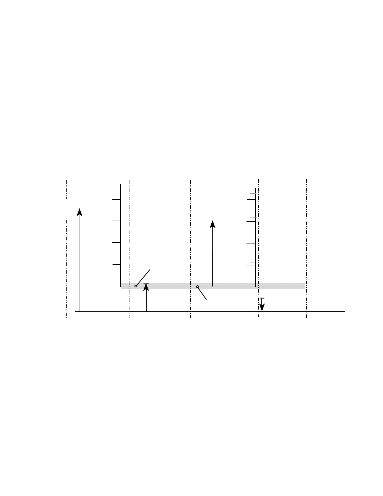
It should be noted that the metric unit of pressure is the Pascal (Pa).
1 Pa = 1 N/m2 (Newton per square meter)
This unit is extremely small, needing 101325 Pascals to equal 1 Bar. To avoid huge numbers in practice, an
agreement has been made to make the Bar equal to 100,000 Pa.
100,000 Pa = 100 kPa = 0.1 MPa = 14.5 psi = 1 Bar
It corresponds with sufficient accuracy for practical purposes with the old metric unit kgf/cm2. More precise
equivalents are 1 STD atm =14.696 psi =1.01325 bar =1.03323 kgf/cm2.
In English units pressure is expressed in psi (almost never referred to as p.s.i. as one would expect), or
pounds per square inch, also relating a force to an area.
1 MPa = 10 Bar = 145 psig
4 ba r
3 ba r
2 ba r
0 ba r
ab s
36 0 T orr,
= -5 33 m ba r
-1 5.8 in Hg
ab s olu te
0
50 0 k P a
40 0 k P a
30 0 k P a
10 0 k P a
Pre ssu re
}
10 5 0 m ba r
30 in H g
ov e r- p res s u re
45 p sig
30 p s i g
15 p sig
Sta n da rd
10 132 5 Pa
14 .6 96 ps ia
Fig. 3.4 the various systems of pressure indication
A pressure in the context of pneumatics is assumed as over-pressure i.e. above atmospheric pressure and is
commonly referred to as gauge (also gage) pressure (GA or psig).
A pressure can also be expressed as absolute pressure (ABS or psia) i.e. a pressure relative to a full
vacuum. In vacuum technology a pressure below atmospheric i.e. under pressure is used.
1013 mbar as a reference. Note that this is not exactly .1 MPa = 100 kPa, although for normal pneumatic
calculations the difference can be ignored.
The various ways of indicating pressure are illustrated in Fig 3.4, using a standard atmospheric pressure of
DO NOT COPY WITHOUT WRITTEN PERMISSION – 9 –
Page 16
P N E U M A T I C T E C H N O L O G Y
a
p
v
p
V
p
p
p
p
V2
1013
.
p
1
T
2
V
PROPERT IES OF GASES
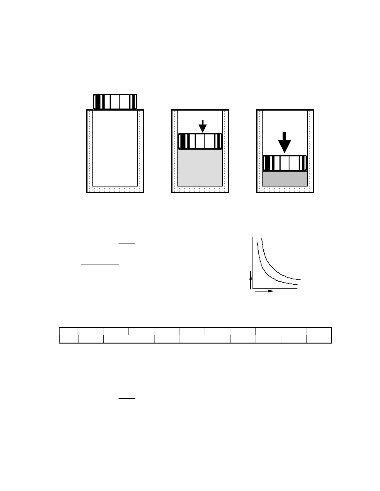
I S O T H E R M I C C H A N GE ( B O Y L E ’ S LA W )
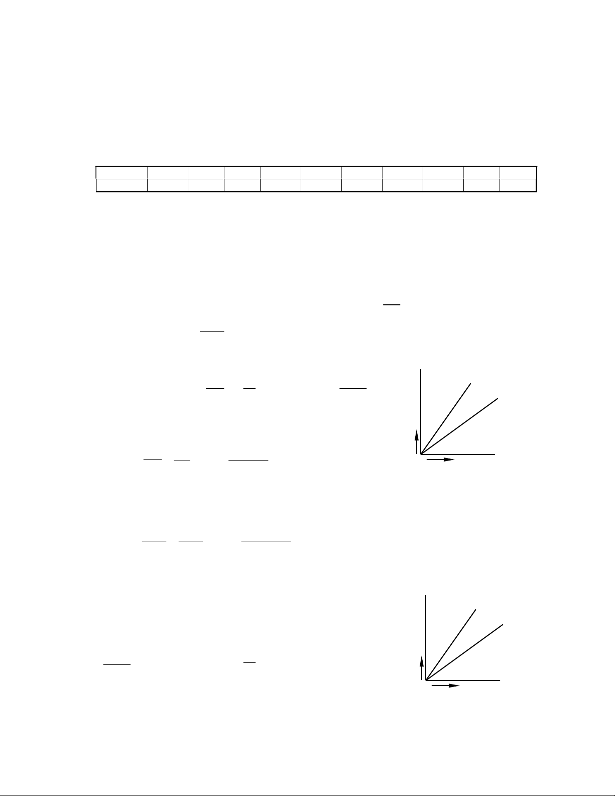
"…with constant temperature, the pressure of a given mass of gas is inversely proportional to its volume”, or:
p · V = constant
F
F
v
= 1;
= 1
= 0.5;
= 2
= 0.2;
= 5
b c
V
1
x
1
Fig. 3.5 illustration of Boyle’s Law
If volume V1 = 1 m3at a standard absolute pressure of 101325 Pa is compressed at constant temperature to a
volume V2 = 0.5 m3 then:
p
V1 = p2 ·V2 p
·
1
i.e. p2 =
The ratio V1/V2 is the “Compression Ratio” Cr
With a gauge pressure of .4 MPa,
The table below shows the compression ratio for pressures from
.1 to 1 MPa
Note the difference between reducing a volume of atmospheric air to half, 1:2.026 and the pressure ratio at a
gauge pressure of .1 MPa (.2
use gauge pressure in MPa +.1!
101325Pa•1 m
0.5m
.
gauge
p
Cr
1 2 3 4 5 6 7 8 9 10
0.987 1.987 2.974 3.961 4.948 5.935 6.922 7.908 8.995 9.882
p1·V1
=
2
V2
3
= 202650 Pa
3
), 1:1.987! But this is theory; – no adjustment is made in practice when we simply
abs
V1
=
1013.4.
V
2
x
= 4.95
2
V
3
x
3 = =
T
If volume V1 = 1 ft3 at a standard absolute pressure of 14.7 psi is compressed at constant temperature to a
volume V2 = 0.5 ft3 then:
p
V1 = p2 ·V2 p
·
1
14.7 psi 1 ft
i.e. p2 =
3
0.5ft
DO NOT COPY WITHOUT WRITTEN PERMISSION – 10 –
p1·V1
=
2
V2
3
= 29.4 psia
Page 17
P N E U M A T I C T E C H N O L O G Y
459
7
273
298
273
499
7
539
7
499
7
Calculating the compression ratio in Imperial or English units is done in the same way, p1 converted to absolute
pressure (add 14.7 psi) divided by 14.7 psi (one atmosphere) or Cr = p1 + 14.7 / 14.7
All compressed air is related at a standard condition (at some over-pressure). Thus, to convert from free air,
CF, (air in the room, measured in Cubic Feet) to SCF (air under pressure, measured in Standard Cubic Feet) the
reference pressure must be noted. CF multiplied by compression ratio will determine SCF. Mathematically, SCF
= CF * CR or SCF = CF * (p1 + 14.7 / 14.7)
P (psig)
Cr
10 20 30 40 50 60 70 80 90 100
1.68 2.36 3.04 3.72 4.4 5.08 5.76 6.44 7.12 7.80
On the other hand it would be wrong to use Boyle’s Law in pneumatics. In the case of tools as well as cylinders
the change is never Isothermic but always Adiabatic change. (See further below and pg. 74-76)
I S O B A R I C C H AN G E
Ch a rles Law
"…at constant pressure, a given mass of gas increases in volume by
Celsius rise in temperature ---
1
for every 0F rise in temperature"
.
Law of Gay Lu s sac
V / T = constant, so
V
V2
1
=
T
1
and V2 =
T
2
V1 T
Example 1: V1 = 100 m3, T 1 = 0°C, T2 = 25°C, V2 = ?
We have to use the absolute temperatures in K, thus
100
=
2V
, V2 =
298•100
= 109.157 m
3
Example 2: V1 = 100 ft3, T 1 = 40°F, T2 = 80°F, V2 = ?
We have to use the absolute temperatures in R (Rankin, for degrees F
or Kelvin for degrees C), thus
100
V2
=
.
, V2 =
.
100 5397
.
.
= 108 ft
3
I S O C H OR I C C H AN G E
T1
1
of its volume for every degree
273
2
p 1
p 2
V
T
"At constant volume, the pressure is proportional to the temperature"
(“Isochoric” comes from the Greek words read “chora”), for
space, field etc., and -, “iso” = equal)
So
p1·p
2
and p2 = p1
T1·T2
T
2
T
1
Where T is the absolute temperature in K (Kelvin) or R (Rankin).
DO NOT COPY WITHOUT WRITTEN PERMISSION – 11 –
V1
V 2
p
T
Page 18
P N E U M A T I C T E C H N O L O G Y
p
p·V
p·V
V
p 1
p 2
v 1
v
2
The previous relationships are combined to provide the general gas equation:
p1 V
T1
1
=
p2 V2
= Constant
T2
This law provides one of the main theoretical bases for calculation to design or select pneumatic equipment
when temperature changes have to be considered.
AD IA B AT IC ( I S E N T R O P I C ) C H A N GE
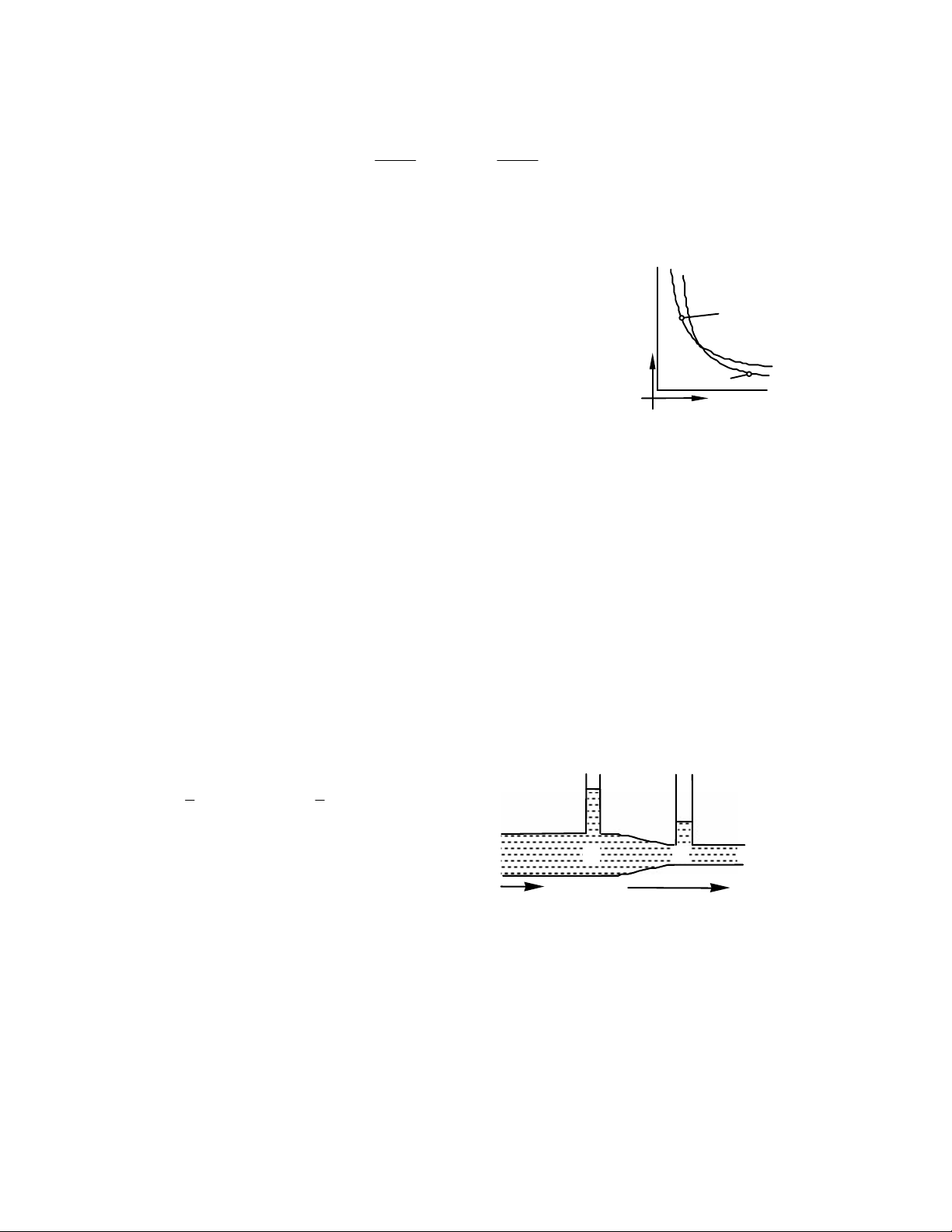
The previous Laws assume a slow change, so only the two considered
magnitudes are changing. In practice, for example --- when air flows into a
cylinder, this is not the case and “adiabatic change” occurs. Then Boyle’s
= c
Law “p·V is constant “ changes to p · V= constant.
It would take too much time to go into greater detail, the diagram
illustrates the difference clearly enough: we see that there is a loss of
= c
volume when pressure builds up quickly. We will meet this law again when
discussing the air consumption of cylinders.
V O L U M E
Due to these mutual relationships between volume, pressure and temperature, it is necessary to refer all data
on air volume to a standardized volume, the normal cubic meter (m
3
). Defined as the air quantity of 1.293 kg
n
mass at a temperature of 320F and an absolute pressure of 760 mm Hg (101325 Pa) and a relative humidity of 0%
--- or the standard cubic foot (scf) that is one cubic foot of air at sea level (absolute pressure of 14.7 psi) having
a temperature of 680F and a relative humidity of 36%.
F L O W
The basic unit for volume flow "Q" is the Normal Cubic Meter per second (m
3
/s). In pneumatic practice
n
volumes are expressed in terms of normal liters per minute (Nl / min) or normal cubic decimeters per minute
(dm3/min). The usual non-metric unit for volume flow is the “standard cubic foot per minute”, (scfm).
Ber nou l li's Equ a tio n
Bernoulli states:
"If a liquid of specific gravity flows horizontally through a tube with varying diameters, the total energy at point 1
and 2 is the same"
or, p1 +
1
· v 12 = p2 +
2
1
· v 2
2
2
The relationship between pressure, the velocity
of the air, and the density of the air () applies to
gases if the flow speed does not exceed 330 m/s
approx. (1083 ft/sec). Velocity (ft/sec) can be
calculated:
Fig. 3.6 illustration of Bernoulli's Law
v = 0.054Q /D2 (Q is cfm, D is i.d. in inches)
Applications of this equation are the venturi tube
and flow compensation in pressure regulators (see
page 43).
AI R H U M I D I T Y
Atmospheric air always contains a percentage of water vapor. The amount of moisture present will depend on
the atmospheric humidity and temperature.
DO NOT COPY WITHOUT WRITTEN PERMISSION – 12 –
Page 19

P N E U M A T I C T E C H N O L O G Y
7.459
68
80
273
0
30
When atmospheric air cools it will reach a certain point at which it is saturated with moisture, this is known as
the dew point. If the air cools further it can no longer retain all the moisture and the surplus is expelled as
miniature droplets to form a condensate (dew).
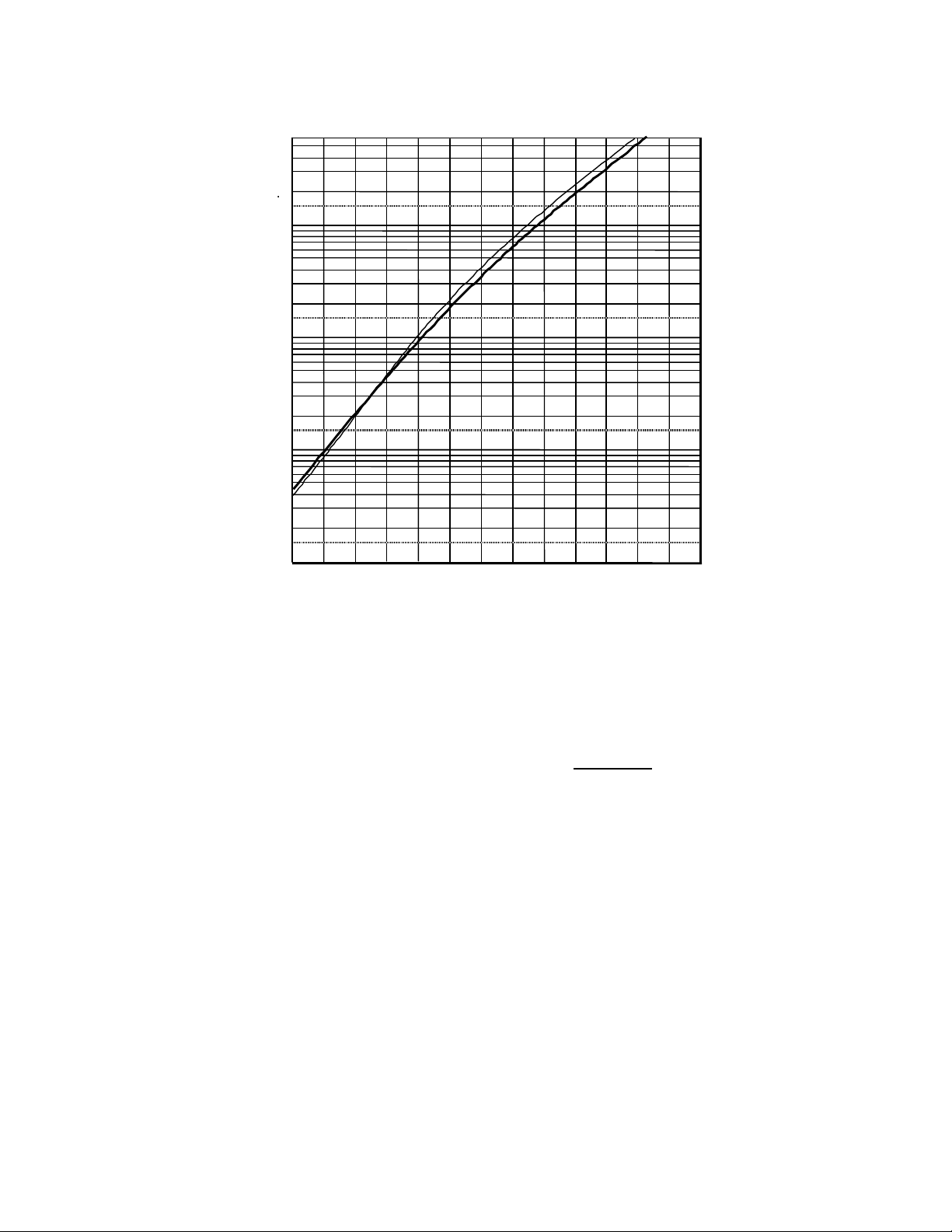
The actual quantity of water that can be retained depends entirely on temperature; 1m3 of compressed air is
only capable of holding the same quantity of water vapor as 1m3 of atmospheric air.
The table below shows the number of grams of water per cubic meter (and cubic feet) for a wide temperature
range from -40°C to +40°C and from –40 0F to 200 0F. The bold line refers to atmospheric air with the volume at
the temperature in question. The thin line gives the amount of water per Normal Cubic dimension. All air
consumption is normally expressed in standard volume; this makes calculation unnecessary.
For the temperature range of pneumatic applications the table below gives the exact values. The upper half
refers to temperatures above freezing, the lower to below freezing. The upper rows show the content of a standard
cubic meter, the lower ones the volume at the given temperature.
Temperature °C 0 5 10 15 20 25 30 35 40
3
g/m
(Normal)
n *
3
g/m
(Atmospheric)
4.98 6.99 9.86 13.76 18.99 25.94 35.12 47.19 63.03
4.98 6.86 9.51 13.04 17.69 23.76 31.64 41.83 54.11
Temperature °C 0 –5 –10 –15 –20 –25 –30 –35 –40
3
g/m
(Normal)
n
3
g/m
(Atmospheric)
4.98 3.36 2.28 1.52 1.00 0.64 0.4 0.25 0.15
4.98 3.42 2.37 1.61 1.08 0.7 0.45 0.29 0.18
Temperature °F 40 60 68 80 100 120 140 160 180
3
g/ft
(Standard) .175 .369 .375 .726 1.368 2.438 4.170 6.834 10.836
*
3
g/ft
(Atmospheric) .137 .362 .375 .71 1.29 2.22 3.67 5.82 8.94
Temperature °F 32 30 20 10 0 -10 -20 -30 –40
3
g/ft
(Standard) .128 .118 .077 .050 .031 .020 .011 .007 .004
3
g/ft
(Atmospheric) .137 .127 .085 .056 .036 .023 .014 .009 .005
Table 3.7 Water Saturation of Air (Dew Point)
3
The term g/ft3 standard refers to a volume at 680F. At 800F its volume is extended to 1+ or 1.026 ft
Consequently to have one standard cubic foot at 800F, 1.03 ft3 of atmospheric air at 800F are required with all its
water content; so that makes 1.03 x 0.71 = 0.726 grams of water. In other words, in the table we are adjusting the
volume of air present from standard, which assumes a temperature of 68oF, to the actual volume present at the
higher temperature.
In addition, the term g/m
3
normal refers to a volume at 00C. At 300C its volume is extended to 1+ or 1.1
n
m3. To have one normal m3 at 300C, 1.1 m3 of atmospheric air at 300C are required with all its water content; so
that makes 1.1 x 31.64 = 35.12 grams of water.
Definitions of the different standards for air, ISO and DIN:
ISO 8778 and JIS B8393
Temperature: 20 C
Pressure: 0.1 MPa (100kPa)
RH: 65%
DIN 1945 (Deutsche Industrie Norm -> German Industrial Standard)
Temperature: 0 C
Pressure: 101325 Pa
RH: 0%
DO NOT COPY WITHOUT WRITTEN PERMISSION – 13 –
Page 20

P N E U M A T I C T E C H N O L O G Y
.1013
.7
Rel ati v e h u mid i ty
With the exception of extreme weather conditions, such as a sudden temperature drop, atmospheric air is
never saturated. The ratio of the actual water content and that of the dew point is called relative humidity, and is
indicated as a percentage.
Relative humidity (r.h.) =
actual water content
saturation quantity (dew point)
· 100%
Example 1: Temperature 25oC, r.h. 65%. How much water is contained in 1 m3?
Dew point 25oC = 24 g/ m3 · 0.65 = 15.6 g/ m3
When air is compressed, its capacity for holding moisture in vapor form is only that of its reduced volume.
Hence, unless the temperature rises substantially, water will condense out.
Example 2: 10 m3 of atmospheric air at 15oC and 65% r.h. is compressed to .6-MPa gauge pressure. The
temperature is allowed to rise to 25oC. How much water will condense out?
From Table 3.7: At 15oC, 10 m3 of air can hold a maximum of 13.04 g/m3 ·10 m3 = 130.4 g
At 65% r.h. the air will contain 130.4 g ·0.65 = 84.9 g (a)
The reduced volume of compressed air at .6-MPa pressure can be calculated:
p1·V1 = p2 V2
1
V
= V
1
p
2
2
MPA1013.
·10 m3 = 1.44 m3
p
From Table 3.7 1.44 m3 of air at 25oC can hold a maximum of 23.76 g ·1.44 = 34.2 g (b)
Condensation equals the total amount of water in the air (a) minus the volume that the compressed air can
absorb (b), hence 84.9 – 34.2 = 50.6 g of water will condense out.
This condensate must be removed before the compressed air is distributed, to avoid harmful effects in the line
and the pneumatic components.
Example 3: Temperature 800F, r.h. 65%. How much water is contained in 1 ft3?
Dew point 800F = 0.71 g/ ft3 · 0.65 = 0.46 g/ ft
3
Observe that the metric chart dimensions would exhibit identical relationships when converted to
Imperial units.
DO NOT COPY WITHOUT WRITTEN PERMISSION – 14 –
Page 21
P N E U M A T I C T E C H N O L O G Y
g H O/m
500
100
3
2
150
50
15
10
5
1.5
1
0.5
0.1
-30 500
100 C
0
Fig. 3.8 Dew points for temperatures from –30 to about +80°C
The bold curve shows the saturation points of a cubic meter at the related temperature, the thin curve at
standard volume. All air consumption is normally expressed in normal volume; this makes calculation
unnecessary.
P R E S SU R E AN D F L O W
The most important relationship for pneumatics is that between pressure and flow.
THEY ARE NOT THE SAME. DO NOT THINK THEY ARE INTERCHANGEABLE TERMS… e.g. a flow control
is not a pressure regulator (repeat as required until retained). It is the relationship between flow and pressure that
we will now consider.
If there is no flow, the pressure in an entire system is the same at every point, but when there is flow from one
point to another, the pressure in the latter will always be lower that at the first. This difference is called pressure
drop. It depends on three values:
• Initial pressure
• Volume of flow
• Flow resistance of the connection
The flow resistance for air has no unit; in electricity its equivalent is Ohm (). In pneumatics, the opposite of
resistance is used, which is conductance, or the ability to allow flow, expressed as the equivalent flow section S.
The equivalent flow section S is expressed in mm2 and represents the area of an orifice in a thin plate (diaphragm)
that creates the same relationship between pressures and flow as the element defined by it. Valves have
complicated orifice shapes, therefore the flow rate through the device is measured first (along with pressure drop,
temperature, etc), and then the device may be assigned the corresponding equivalent flow section. Other
standards include the kv or Cv factor (a dimensionless number referring to a flow coefficient) --- Consider Cv as a
conductance value. An easy approximation would be that:
Cv of 1 = 18 S mm2, e.g. an equivalent orifice size of 18 mm2 equals the flow of a Cv of 1. (Note: the original
definition of Cv stated that a Cv of 1 = a flow capacity of 1 gpm with a pressure drop of 1 psi)
DO NOT COPY WITHOUT WRITTEN PERMISSION – 15 –
Page 22
P N E U M A T I C T E C H N O L O G Y
Q
(54.44 l /
min)
S = 1 mm
2
0
20 40 80 100 120
60
.9
.6
.4
.3
.2
.1
(dm /min)
n
Q
p
The relationship between pressure and flow is by definition the same as in electricity, where “voltage drop
equals current times resistance”. This can be transformed for pneumatics to “pressure drop equals flow divided by
Flow Section”, only, while the electric units are directly proportional, the relationship for air is very complex and
never simply proportional. In electricity, a current of 1 A (one Ampere) creates over a resistor of 1 Ohm a voltage
drop of 1 Volt, regardless if this drop is from 100 to 99 or from 4 to 3 volts. The pressure drop over the same
object and with the same standard volume flow varies with the initial pressure and also with the temperature.
Reason: The compressibility of the air.
For defining one of the four interrelated data, mentioned previously, from the other three, we require a diagram.
.10
(MPa)
Sonic Flow
n
3
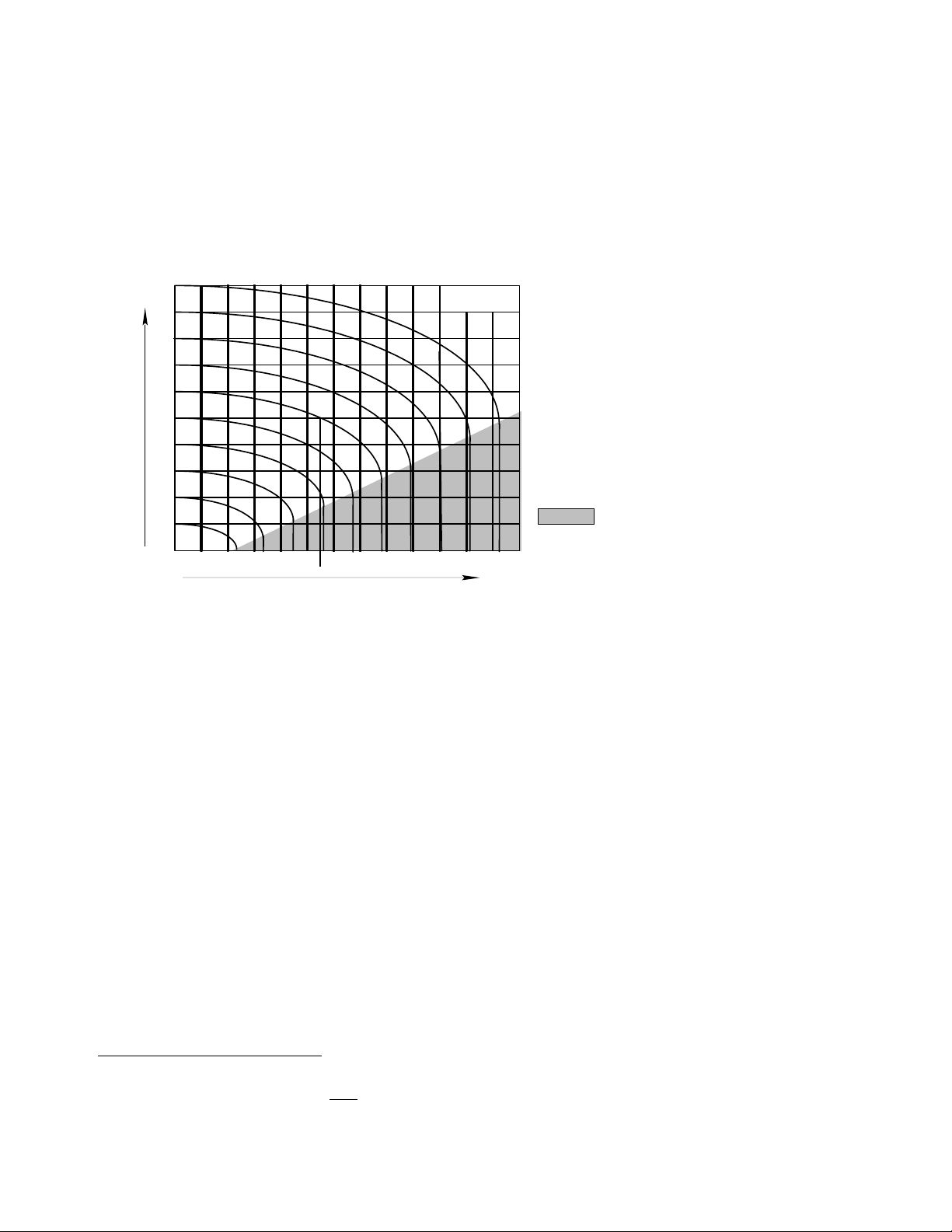
Fig. 3.9 Diagram showing the relationship between pressure and flow for an orifice with an equivalent Flow
Section of 1 mm2
The triangle in the lower right corner marks the range of “sonic flow speed”. When the airflow reaches a speed
close to the speed of sound flow can no longer increase --- whatever the difference of pressure between input
and output might be. As you can see, all the curves drop vertically inside this triangle. This means that the flow no
longer depends on the pressure drop, but only on the input pressure.
Use of the dia g ram :
The pressure scale at the left side indicates both input and output pressure. At the first vertical line on the left,
which represents a zero flow, input and output pressures are the same. The various curves, for input pressures
from 1 to 10 bar, indicate how the output pressure decreases with increasing flow.
Example 1: Input pressure .6 MPa, pressure drop 1 bar = output pressure .5 MPa. We follow the curve “.6” to the
point where it cuts the horizontal line marked “.5”. From there we go vertically down to the Flow scale
(dotted line) and find about 55 l/min. The 54.44 l/min written below that line is the exact value, calculated
with the formula further below. These input and output pressures define the so-called “Standard Volume
Flow Qn”, a figure found in valve catalogues for a quick comparison of the flow capacity of valves.
The Volume Flow of 54.44 l/min applies to an element (Valve, fitting, tube etc.) with an equivalent orifice “S” of
1 mm2. If an element has for example an “S” of 4.5 mm2, the flow would be 4.5 times higher, in this case 4.5 ·
54.44 l/min = 245 l/min
Sound is, after all, vibrating air molecules. Thus the “speed of sound” (sonic condition, Mach #) is the terminal velocity for
air movement. For compressed air to flow there must be a pressure drop --- and maximum flow occurs at a certain % pressure
drop. There can be a greater pressure drop (up to 100%) but maximum flow (for whatever size orifice) occurs at 47% of p1.
DO NOT COPY WITHOUT WRITTEN PERMISSION – 16 –
Page 23

P N E U M A T I C T E C H N O L O G Y
1.024
Example 2: Given an element with an “S” of 12 mm2, a working pressure of .7 MPa and an air consumption of 600
l/min. What output pressure will result?
A flow of 600 l/min through an “S” of 12 mm2 corresponds with a flow of
600
= 50 l/min through an
12
equivalent section of 1 mm2. We need this conversion for the use of the diagram of fig. 3.9. We now follow
the curve starting at .7 MPa until it intersects with the vertical line for 50 l/min. A horizontal line towards the
pressure scale indicates about .63 MPa.
Fo r mul a e:
When it is required to have a more exact value than that which can be estimated from the diagram, the flow
can be calculated with one of the two following formulae.
A glance at the diagram of Fig. 3.9 makes it clear, that there must be different formulae for the sonic flow range
and the “subsonic” flow condition. The transient from subsonic to sonic flow is reached, when the pressure ratio of
the absolute input and output pressures is less or equal to 1.896:
Sonic flow: p1 + .1013 <.1896 · (p2 +.1013)
Subsonic flow: p1 + .1013 > .1896 · (p2 +.1013)
The Volume flow Q for subsonic flow equals:
Q = 22.2 · S · (p2 + .1013) · (p1 –p2) (l/min)
And for sonic flow:
Q = 11.1 · S · (p1 + .1013) (l/min)
3
Where S in mm2 and p in bar; 22.2 is a constant with the equation
dm
, which is liters per 60 seconds and per
60 N s
force (defined by the ruling pressure).
Note that a pneumatic system can never operate satisfactorily under sonic flow conditions, as a supply
pressure of, for example, .6 MPa would give us less than .27 MPa for work.
Example 3: We calculate the flow; assumed in example 2, with an input pressure of .7 MPa, a total equivalent
flow section of 12 mm2 for valve and tubes and the calculated working pressure of .63 MPa:
Q = 22.2 · 12 · 7.313·0.7 = 602.74 l/min.
This shows that the accuracy of the diagram is sufficient for practical pneumatic use.
In Imperial units
The formula for subsonic flow:
P2pC
Q
scfm
av
DO NOT COPY WITHOUT WRITTEN PERMISSION – 17 –
Page 24
P N E U M A T I C T E C H N O L O G Y
And for sonic flow: Q=0.486 Cv (p2+14.7)
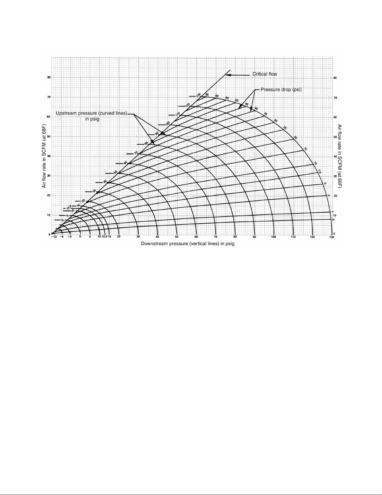
Fig. 3.10 Airflow curves for a device having a Cv of 1.0 (derived from the above two formulae)
Flow at a certain pressure drop can be derived from Fig. 3.10.
Select the p1 (upstream pressure) from the diagonal line and follow straight across to the vertical axis --- this is the
maximum flow at that pressure. Now select a pressure drop from either the bottom numbers (downstream
pressure) or from the numbers on the outer arc of the graph (p in psi). Next, follow the curve of the selected p1
until it intersects your p2 or p selection and then follow straight across from that point to the vertical axis to find
flow in scfm.
The results are linear, e.g. if the device in application has a Cv of 2.0 multiply your result from Fig. 3.10 by 2, Cv of
0.5 multiply by one half, etc.
Observe that critical flow occurs at a certain pressure drop – to discover this for yourself, find 100 psig (which is
114.7 psia) on the diagonal critical flow line. Drop straight down to the p2 horizontal axis and note that p2 is
approximately 46 psig (or 60.7 psia). This confirms that a pressure differential of (approximately) 47% produces
maximum flow. There can be a greater drop in pressure but flow will not increase. Looked at another way,
maximum flow occurs when p2
abs
= p1
* 0.53, or in our example 60.7 psia = 114.7 psia * 0.53. Although we
abs
state that for all practical purposes, flow does not increase once sonic velocity has been reached, in tests
conducted with precision instruments, it has been observed that the flow rate does increase slightly. This increase
is so very slight that it is discounted in actual practice.
Observe that use of Fig. 3.10 requires a known pressure drop. In real world applications (with so many variables)
this knowledge is difficult to come by, so the cautious individual will rely on a safe estimate of what a desired
pressure drop ought to be. Predicting a system’s actual pressure drop is very difficult. The NFPA (National Fluid
Power Association, a U.S. standards group) recommends a maximum pressure drop of 15%.
DO NOT COPY WITHOUT WRITTEN PERMISSION – 18 –
Page 25

P N E U M A T I C T E C H N O L O G Y
Example 1: How many scfm will flow through a valve with a Cv of 1.0 given a supply pressure of 80 psig and a
20-psi pressure drop?
From the chart Fig. 3.10 find 80 psig on the critical flow line. Next, find 60 psig (80 psig minus a 20 psi
pressure drop) on the horizontal axis at the bottom. Moving vertically from the 60 psig find the intersection
of the 80 psig curve (from the critical flow line) and move straight across to the vertical axis where the
answer of approximately 38 scfm will be found.
Example 2: A flow of 40 scfm is required for an application and supply is 60 psig. What size Cv must all
components exceed?
From the chart Fig. 3.10 find the scfm of a Cv of 1.0. If the application flows to atmosphere (e.g. a “blow-
off”) the critical flow scfm will be used; if the application involves other devices (e.g. cylinders or actuators)
use the rule of thumb 10 psi pressure drop. Note that some designers typically use a 5 psi or 2 psi pressure
drop when speeds are critical or a more conservative sizing solution is required. Observe that at a supply
pressure of 60 psig, an orifice with a Cv of 1.0 will flow approximately 36 scfm. With a 10 psi pressure drop
(p2 is 50 psig) the flow is approximately 25 scfm --- and thus a Cv of more than 1.6 will provide 40 scfm (40
scfm / 25 scfm = 1.6).
For more information on Cv please refer to pages 92 and following regarding dealing with sizing of components
and systems.
Indication of flow characteristics:
The flow rate of a pneumatic valve is an important characteristic of its performance characteristic. In order to
determine a meaningful flow rate for a valve, a standardized, repeatable test method is required. This test method
is defined by the International Organization for Standardization ISO 6358-1989. Other national or customary
pneumatics standards such as VDI 2173 (Germany) and JIS B8390-2000 (Japan) are based on this ISO standard.
ISO 6358-1989, JIS B 8390-2000:
Based on the sonic conductance C [dm3/s*bar] characteristic and the critical pressure ratio b [-], which is defined
in ISO6358-1989 and JIS B 8390-2000, it is possible to determine the flow rate of a pneumatic component.
Sonic conductance C:
The air-passages of a pneumatic component (e.g. directional valve) consist of a number of flow resistances,
caused by deflecting and/or redirecting air flow. These resistances directly affect the flow capacity of the
component. The sonic conductance C, defines the maximum flow capacity in sonic flow conditions.
Critical pressure ratio b:
The Critical pressure ratio b constitutes the pressure ratio between the downstream pressure (p2) and the
upstream pressure (p1). In conditions where the effective pressure ratio (p2 to p1) is less than the rated b-value; it
is presumed that sonic flow or choked flow condition exists. If it is greater than the b-value; subsonic flow condition
exists.
Therefore, the pressure ratio inducing sonic conductance is for each component diverse, and depends on its
construction. Directional valves have rated b-values from 0.16 to 0.5. Speed controls, fittings and tubing generally
have a b-value of 0.5.
Note: The critical pressure ratio b of an ideal nozzle is 0.528.
DO NOT COPY WITHOUT WRITTEN PERMISSION – 19 –
Page 26
P N E U M A T I C T E C H N O L O G Y
Measuring sonic conductance C and critical pressure ratio b:
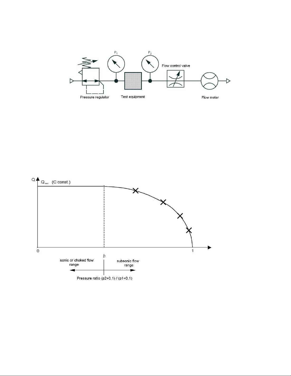
Fig 3.11: Test circuit based on ISO 6358-1989, JIS B 8390-2000 (simplified circuit)
In order to obtain the flow capacity of a pneumatic resistance, it is necessary to determine the value for sonic
conductance first. To determine this value a constant supply pressure (>0.3 MPa gauge) is needed. By opening
the flow control valve, the pressure decreases and the flow increases. By continuing to open the control valve, flow
will increase until sonic conductance (choked flow) on the narrowest cross section in the test item is reached. With
the maximum flow, it is now possible to calculate the sonic conductance value C (Formula #1 below solved for C).
To reduce variations in the calculation of the respective b-values, four measuring points of approx. 80, 60, 40 and
20 % in the subsonic flow range are selected and used for the calculation of the b-values. The arithmetic mean of
all calculated b-values will be the rated critical pressure ratio b (Formula #2 solved for b). These four points are
also used to chart the graph.
Fig 3.12: Flow behavior in relationship to pressure ratio
If the b-value is known, use the following simple formula to calculate p2, which will be the downstream pressure
when sonic flow occurs.
Example:
A valve has a rated critical pressure ratio b of 0.36. The supply pressure (p1) is 0.6 MPa. At what output pressure
(p2) will the flow in the valve change form subsonic to sonic flow?
DO NOT COPY WITHOUT WRITTEN PERMISSION – 20 –
Page 27

P N E U M A T I C T E C H N O L O G Y
1.06.
0
p
b
p
Formulas to calculate air flow rates Q:
If the pressure ratio is less or equal to the rated b-value:
p
p
1.01
A sonic condition exists.
In that case use the following formula #1:
If the pressure ratio is greater than the rated b-value:
p
p
1.01
A subsonic condition exists.
In that case use the following formula #2:
Q = Flow [dm3/min], [l/min]
C = Sonic conductance [dm3/(s*bar)]
b = Critical pressure ratio [-]
p1 = Upstream pressure [MPa]
p2 = Downstream pressure [MPa]
t = Temperature [°C]
Example 1:
C = 2dm3/(s*bar)
b = 0.3
p1 = 0.6MPa
p2 = 0.5MPa
t = 20°C
1.02
1.01
pbp
1.02
b
pCQ
1.02
b
pCQ
1.05.0
1.0)1.01(2
293
)1.01(600
273
1)1.01(600
3.086.0
MPap 152.01.0)1.06.0(36.02
t
p
p
1.02
1.01
1
2
b
293
273
tb
The pressure ratio of 0.83 is greater than 0.3, therefore use formula #2 for subsonic flow
DO NOT COPY WITHOUT WRITTEN PERMISSION – 21 –
Page 28
P N E U M A T I C T E C H N O L O G Y
0.86
1)1.06.0(2600
1.06.0
3.01
1.05.0
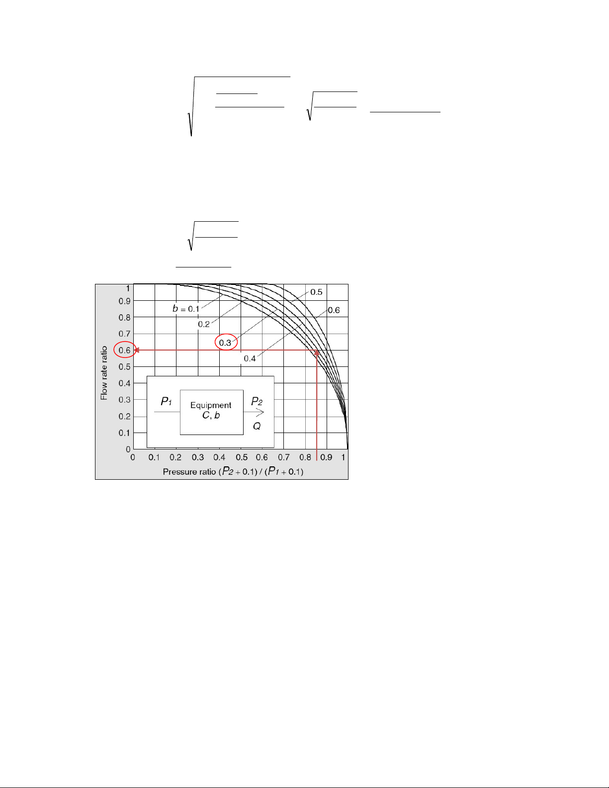
Alternatively to the complex formula above, formula #1 in conjunction with the graph below may be used to
determine the flow rate in subsonic conditions instead.
Example 2:
)1.06.0(2600 NlQ
293
20273
2
3.0
293
20273
NlQ
min/54.508
min/840
min/5046.0min/840 NlNlQ
Fig.12: Flow rate ratio graph to correct for subsonic flow
The standard flow Qn :
Some pneumatic vendors provide, besides the C- and b-values, additional information on the flow capacity,
indicated as Qn in min/
flow of free air min)/(
pressure of 0.5 MPa.
It is recommended to calculate the standard flow Qn, using the formula #2 (p1 = 0.6MPa, p2 = 0.5MPa), or with
the following rules of thumb:
Qn = 227 x C if b = 0.10
Qn = 233 x C if b = 0.15
Qn = 240 x C if b = 0.20
Qn = 247 x C if b = 0.25
Qn = 254 x C if b = 0.30
Qn = 263 x C if b = 0.35
Qn = 272 x C if b = 0.40
Qn = 282 x C if b = 0.45
Qn = 294 x C if b = 0.50
l (normal or standard liter/min). This standard flow Qn is defined as follows: Standard
n
l through a pneumatic component at an upstream pressure of 0.6 MPa and a downstream
n
DO NOT COPY WITHOUT WRITTEN PERMISSION – 22 –
Page 29

P N E U M A T I C T E C H N O L O G Y
0.5
Flow section S [mm2]:
The Flow section S is commonly used for fittings and tubing. The relationship between flow section S and sonic
conductance C is described in the formulas below.
0.5
CS or
S = Flow section [mm
C = Sonic conductance [dm
Note: Fittings and tubing have generally a rated b-value of 0.5
S
C
2
]
3
/(s x bar)]
DO NOT COPY WITHOUT WRITTEN PERMISSION – 23 –
Page 30
P N E U M A T I C T E C H N O L O G Y
Displacement Compressors
Reciprocating
Rotary
Piston
Diaphragm
Vane
Screw
44 AAIIRR CCOOMMPPRREESSSSIIOONN AANNDD DDIISSTTRRIIBBUUTTIIOONN
COMP RES SOR S
A compressor converts the mechanical energy of an electric or combustion motor into the potential energy of
compressed air.
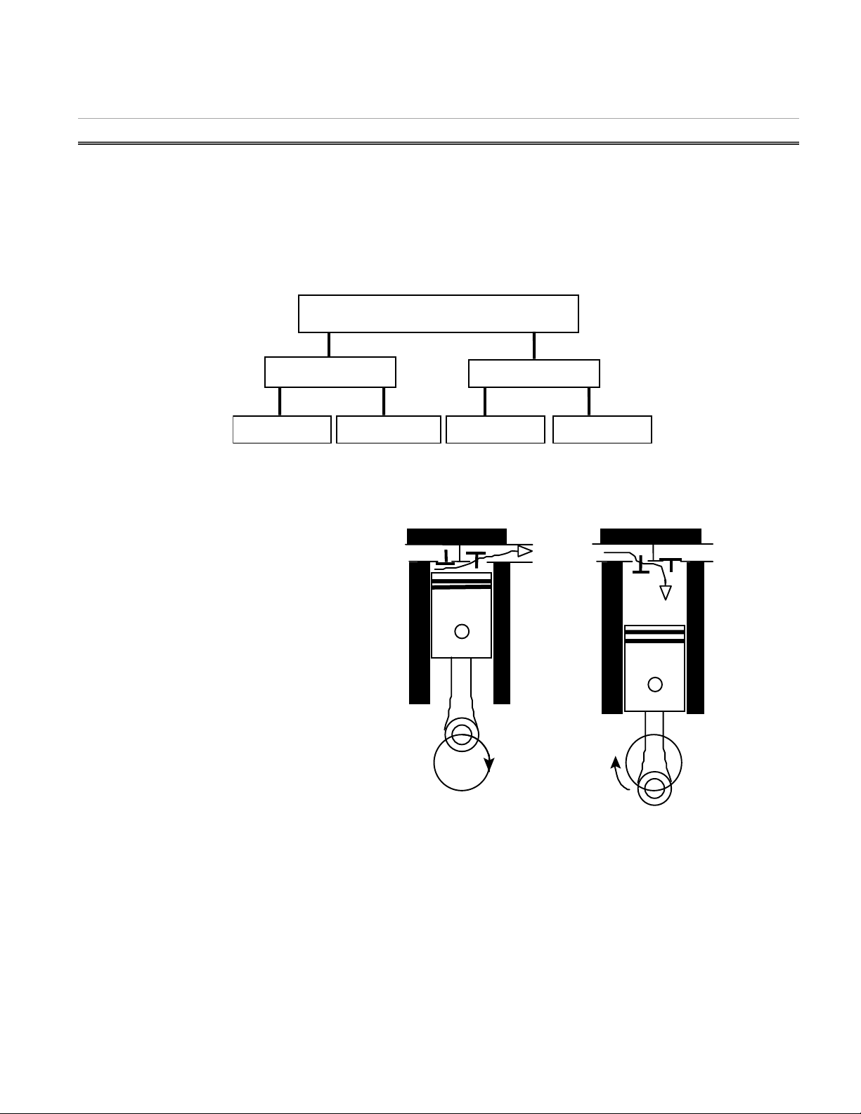
Air compressors fall into two main categories: Reciprocating and Rotary.
The principal types of compressors within these categories are shown in Fig 4.1.
Fig. 4.1 The Main Compressor types used for Pneumatic Systems
R E C I PR O C A T IN G C O M P R E S S O R S
Sin gle sta g e P i sto n Co mpre sso r
Air taken in at atmospheric pressure is
compressed to the required pressure in a single
stroke.
Downward movement of the piston increases
volume to create a lower pressure than that of
the atmosphere, causing air to enter the cylinder
through the inlet valve.
At the end of the stroke, the piston moves
upwards, the inlet valve closes as the air is
compressed, forcing the outlet valve to open
discharging air into a receiver tank.
This type of compressor is generally used in
systems requiring air in the .3-.7 MPa range.
Fig. 4.2 Single Stage Piston Compressor
Tw o st age Pist o n C omp r ess o r
In a single-stage compressor, when air is compressed above .6 MPa, the excessive heat created greatly
reduces the efficiency. Because of this, piston compressors used in industrial compressed air systems are usually
two stages.
Air taken in at atmospheric pressure is compressed in two stages to the final pressure.
DO NOT COPY WITHOUT WRITTEN PERMISSION – 24 –
Page 31
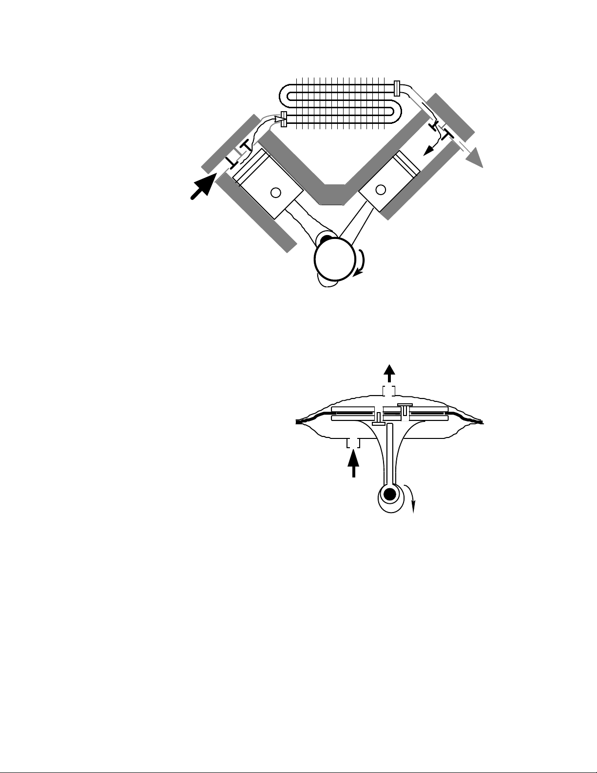
If the final pressure
Intercooler
Intake
Output
Intake
Output
is .7 MPa, the first
stage normally
compresses the air to
approximately .3 MPa,
after which it is cooled.
It is then fed into the
second stage cylinder
that compresses it to .7
MPa.
The compressed air
enters the second
stage cylinder at a
greatly reduced temperature after passing
through the inter-cooler,
thus improving
efficiency compared to
that of a single stage
unit. The final delivery
temperature may be in
the region of 1200C
(2500 F).
P N E U M A T I C T E C H N O L O G Y
Fig. 4.3 Two Stage Piston Compressor
Di a phr a gm c omp ress o r
Diaphragm compressors provide compressed
air in the .3-.5 MPa range totally free of oil and are
therefore widely used by food, pharmaceutical and
similar industries.
The diaphragm provides a change in chamber
volume. This allows air intake in the down stroke
and compression in the up stroke.
Smaller types, with a fractional HP electric
motor and small reservoir make possible portable
compressors, ideal for spray painting.
Fig. 4.4 Diaphragm Compressor
DO NOT COPY WITHOUT WRITTEN PERMISSION – 25 –
Page 32
P N E U M A T I C T E C H N O L O G Y
increasing favor.
R O T A R Y C O M P R E S S O RS
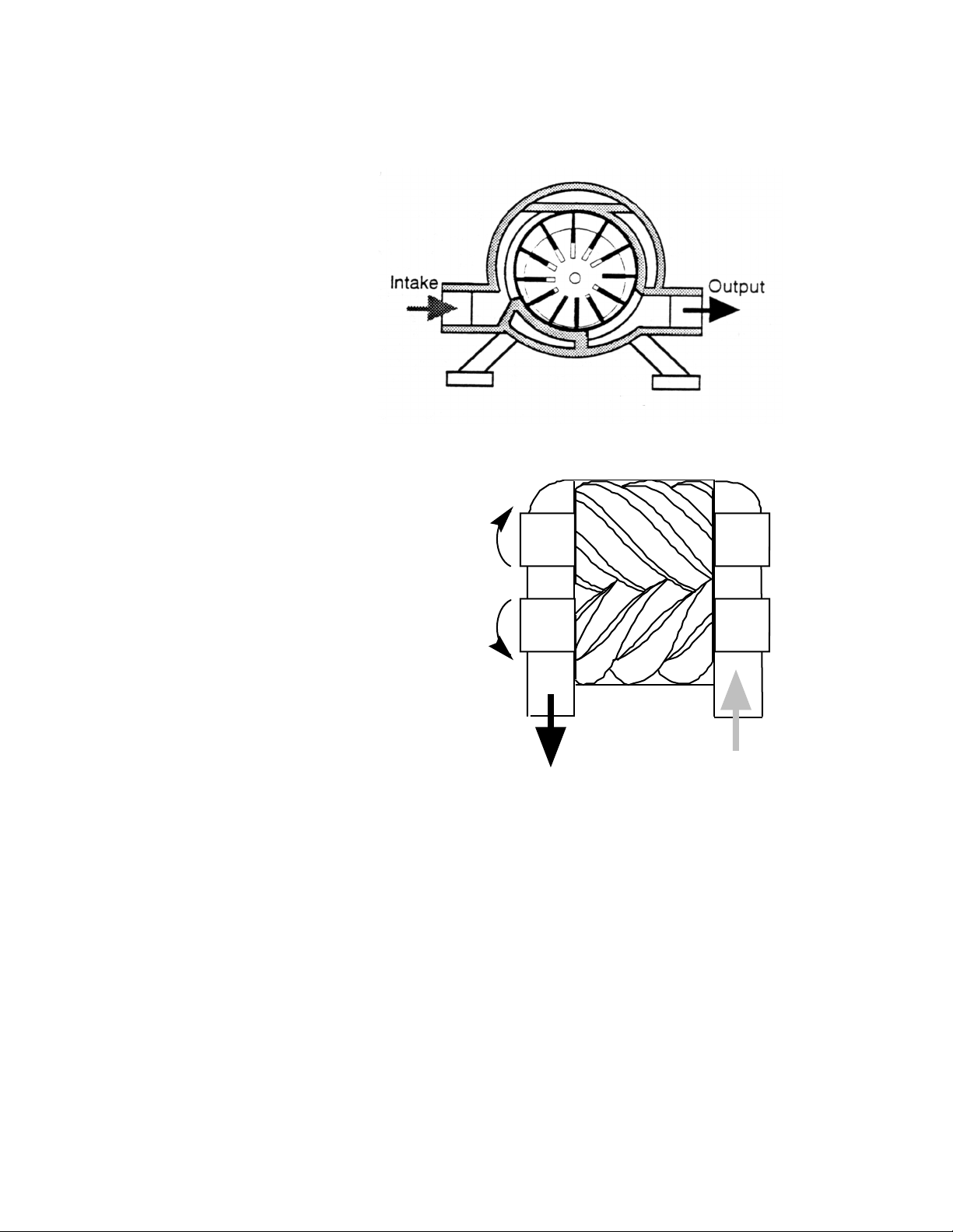
Ro t ary sli d ing van e co m pre s sor
This has an eccentrically mounted
rotor having a series of vanes sliding
in radial slots.
As the rotor rotates, centrifugal
force holds the vanes in contact with
the stator wall and the space between
the adjacent blades decreases from
air inlet to outlet, so compressing the
air.
Lubrication and sealing is achieved
by injecting oil into the air stream near
the inlet. The oil also acts as a coolant
to limit the delivery temperature.
Scr e w c o mp r ess o r
Two meshing helical rotors rotate in opposite
directions. The free space between them
decreases axially in volume and this compresses
the air trapped between the rotors (Fig 4.6.).
Fig. 4.5 Vane Compressor
Oil flooding provides lubrication and sealing
Drive
between the two rotating screws. Oil separators
remove this oil from the outlet air.
Continuous high flow rates in excess of 400
m3/min are obtainable from these machines at
pressures up to 1.0 MPa.
More so than the Vane Compressor, this type
of compressor offers a continuous pulse-free
delivery.
The most common industrial type of air
compressor is still the reciprocating machine,
Fig 4.6 Screw Compressor Principle
IntakeOutput
although screw and vane types are finding
C O M P R E S S OR R A T IN G
A compressor capacity or output is stated as Standard Volume Flow, given in m
3
/s or /min, dm
n
3
/s or liters
n
/min. The capacity may also be described as displaced volume, or ''Theoretical Intake Volume'', a theoretical
figure. For a piston compressor it is based on:
Q (l/min) = (piston area in dm2) x (stroke length in dm) x (# of first stage cylinders) x (rpm)
Q (cfm) = ((piston area in in2) x (stroke length in inches) x (# of first stage cylinders) x (rpm)) / 1728
In the case of a two-stage compressor, only the first stage cylinder should be considered.
The effective delivery is always less due to volumetric and thermal losses.
The volume loss is inevitable, as it is not possible to discharge all of the compressed air from the cylinder at the
end of the compression stroke; there is some space left, the so-called “dead volume”.
DO NOT COPY WITHOUT WRITTEN PERMISSION – 26 –
Page 33
P N E U M A T I C T E C H N O L O G Y
90%
70%
80%
60%
.12 .1 1 .1 0 .9 .8 .7 .6 .5 .4
To tal
E fficienc y
S ingle S tage
Tw o S ta ge
Thermal loss occurs due to the fact that during compression the air assumes a very high temperature;
therefore its volume is increased and decreases when cooling down to ambient temperature (see Charles Law in
section 3).
Vol ume t ric Eff i cie n cy
The ratio:
free air delivered
displacement
expressed as a percentage is known as the volumetric efficiency, and will vary with
the size, type and make of machine, number of stages and the final pressure. The volumetric efficiency of a twostage compressor is less than that of a single stage type as both the first and second stage cylinders have dead
volumes.
Th e rma l an d Ov e ral l Ef f ici e ncy
Beside the losses described above, there are also thermal effects, which lower the efficiency of the air
compression. These losses reduce the overall efficiency further depending on the compression ratio and load. A
compressor working at almost full capacity accumulates great heat and loses efficiency. In a two-stage
compressor, the compression ratio per stage is less and the air, partly compressed in a first stage cylinder, is
cooled in an inter-cooler before compression to final pressure in a second stage cylinder.
Example: If the atmospheric air, taken in by a first stage cylinder, is compressed to a third of its volume, the
absolute pressure at its outlet is .3 MPa. The heat, developed by this relatively low compression, is
correspondingly low. The compressed air is then led to a second stage cylinder, through the inter-cooler,
and then again reduced to a third of its volume. The final pressure is then .9 MPa abs.
The heat developed by compressing the same air volume in a single stage directly from atmospheric
pressure to .9 MPa
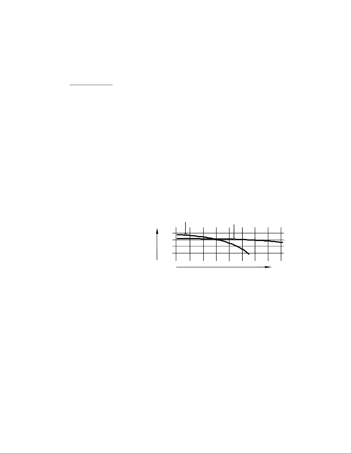
The diagram in Fig. 4.7
compares the typical overall
, would be much higher and the overall efficiency severely reduced.
abs
efficiencies of single and two
stage compressors with
various final pressures.
For low final pressures, a
single stage compressor is
better, as its pure volumetric
efficiency is higher. With
increasing final pressure
however, thermal losses
become more and more
Fig. 4.7 Overall efficiency Diagram
Final P re s sure (M Pa )
important and two stage types,
having a higher thermal
efficiency become preferable.
The specific energy consumption is a measure of the overall efficiency and can be used to estimate the
generating cost of compressed air. As an average figure, it can be assumed that one kW of electrical energy is
needed for the production of 120-150 l/min (= 0.12…0.15 m
3
/ min / kW), for a working pressure of .7 MPa or 1
n
HP of electrical energy is needed to produce 4~5 cfm at a working pressure of (.7 MPa) (31-39 scfm).
Exact figures have to be established according to the type and size of compressor.
COMP RES SOR AC CESS ORI ES
AI R R E C E I V E R
An air receiver is a pressure vessel of welded steel plate construction, installed horizontally or vertically directly
downstream from the aftercooler to receive the compressed air, thereby damping the initial pulsations in the air
flow.
DO NOT COPY WITHOUT WRITTEN PERMISSION – 27 –
Page 34

P N E U M A T I C T E C H N O L O G Y
Its main functions are to store sufficient air to meet temporary heavy demands in excess of compressor
capacity, and minimize frequent "loading" and "unloading" of the compressor, but it also provides additional cooling
to precipitate oil and moisture carried over from the aftercooler, before the air is distributed further. To this end it
is an advantage to place the air receiver in a cool location.
The vessel should be fitted with a safety valve, pressure gauge, automatic drain, and inspection covers for
checking or cleaning inside --- and may need to be approved by some governing body (e.g. ASME in North
America).
Siz ing a r e cei v e r
Air receivers are sized according to the compressor output, size of the system and whether the demand is
relatively constant or variable.
Electrically driven compressors in industrial plants, supplying a network, are normally switched on and off
between a minimum and a maximum pressure. This control is called “automatic”. This needs a certain minimum
receiver volume to avoid over-frequent switching.
Mobile compressors with a combustion engine are not stopped when a maximum pressure is reached, but the
suction valves are lifted so that the air can freely flow in and out of the cylinder without being compressed (often
referred to as “unloading”). The pressure difference between compressing and running idle is quite small. In this
case only a small receiver is needed.
For industrial plants, the rule of thumb for the size of the reservoir is:
Air receiver capacity compressor output of compressed air per minute. (Not Free Air)
Some would suggest a factor of x1.5 when sizing a receiver for a large system, and as much as x3 for small
compressors.
Example: compressor delivery 600 cfm (free air) and an output pressure of .7 MPa (100 psi). What size receiver
is required?
Where V = capacity of receiver
Q = compressor output (cfm)
Pa = atmospheric pressure
P1 = compressor output pressure
V = (600*14.7)/ (100+14.7) = 77 ft3 as a minimum number, a prudent suggestion might begin with 120 ft3.
I N L E T F I L T E R
A typical city atmosphere can contain 40 million solid particles, i.e. dust, dirt, pollen, etc. per m3. If this air were
compressed to .7 MPa, the concentration would be 320 million parts/m3 or 7.8 million parts/ft3. An important
condition for the reliability and durability of a compressor is that it must be provided with a suitable and efficient
intake filter to prevent excessive wear of cylinders, piston rings, etc. which is caused mainly by the abrasive effect
of these impurities.
The filter must not be too fine as the compressor efficiency decreases due to high resistance to airflow, and so
very small particles (2-5 µ) cannot be removed.
The air intake should be sited so that, as far as possible, clean dry air is drawn in, with intake piping of
sufficiently large diameter to avoid excessive pressure drops. When a silencer is used, it may be arranged to
include the air filter, which will be located upstream of the silencer position, so that it is subjected to minimum
pulsation effects.
DO NOT COPY WITHOUT WRITTEN PERMISSION – 28 –
Page 35
P N E U M A T I C T E C H N O L O G Y
Cooling Water IN
Cooling Water OUT
Air Input
Air Output
AI R DEHYDR AT ION
AF TE R C O O L E R S
After final compression, the air will be hot and when cooling, will deposit water in considerable quantities in the
airline system, which should be avoided. The most effective way to remove the major part of this condensate is to
subject the air to aftercooling, immediately after compression.
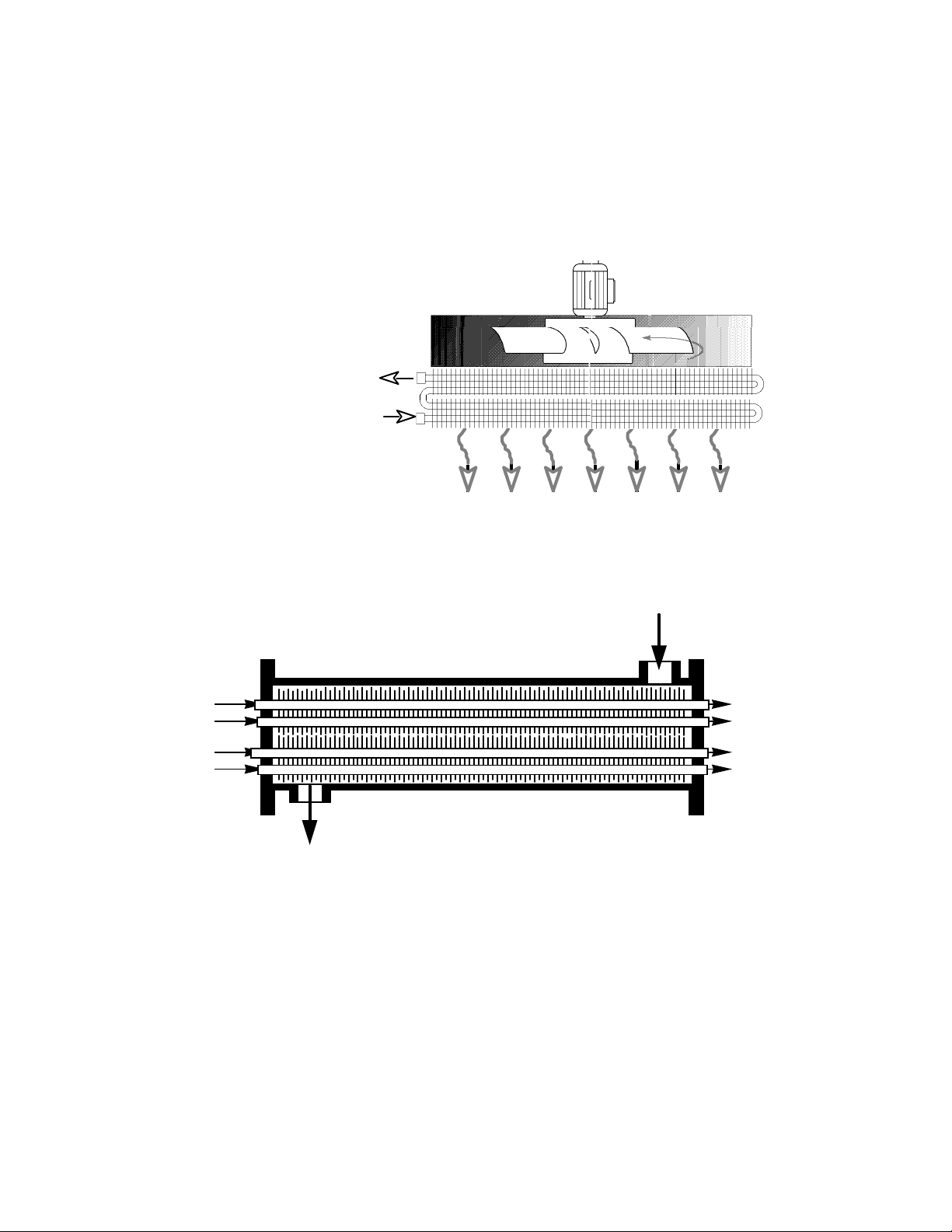
Aftercoolers are heat exchangers, being either air-cooled or water-cooled units.
Ai r co o led
Consisting of a nest of tubes
through which the compressed air
flows and over which a forced draft
of cold air is passed by means of a
fan assembly. A typical example is
shown in Fig.4.8.
The outlet temperature of the
cooled compressed air should be
approximately 400C (105 0F), given
an inlet air temperature of 70oC
(158oF).
Fig. 4.8 Principle of an Air Cooled Aftercooler
Wat e r c o ole d
A water-cooled aftercooler is essentially a steel shell housing tubes with water circulating on one side and air on
the other, usually arranged so that the air flows in the opposite direction of the water flowing through the cooler.
The principle is shown in Fig. 4.9
Fig. 4.9 Principle of a Water Cooled Aftercooler
A water-cooled aftercooler should ensure that the air discharged would be approximately 40oC (105 0F) with
300C being the inlet temperature of the cooling water. The major benefit of the water-cooled aftercooler is that it
will accommodate inlet air temperatures up to 180oC (3500 F).
An automatic drain attached to or integral with the aftercooler removes the accumulated condensation.
Aftercoolers should be equipped with a safety valve, pressure gauge, and it is recommended that
thermometers or sensors to monitor air and water temperatures are included.
DO NOT COPY WITHOUT WRITTEN PERMISSION – 29 –
Page 36
P N E U M A T I C T E C H N O L O G Y
AI R D R Y E R S
Aftercoolers cool the air to approximately 40oC (1050 F). The control and operating elements of the pneumatic
system will normally be at ambient temperature [approx. 20CC (680 F)]. This may suggest that no further
condensate will be precipitated, and that the remaining moisture passes out with the exhaust air released to
atmosphere. However, the temperature of the air leaving the aftercooler may be higher than the surrounding
temperature through which the pipeline passes, for example during nighttime. This situation cools the
compressed air further, thus condensing more of the vapor into water.
The measure employed in the drying of air is lowering the dew point, which is the temperature at which the air
is fully saturated with moisture (i.e.100% humidity). The lower the dew point, the less moisture remains in the
compressed air.
There are three main types of air dryers available, which operate on an absorption, adsorption, or refrigeration
process.
Ab s orp t ion (d e liq u esc e nt) Dry i ng
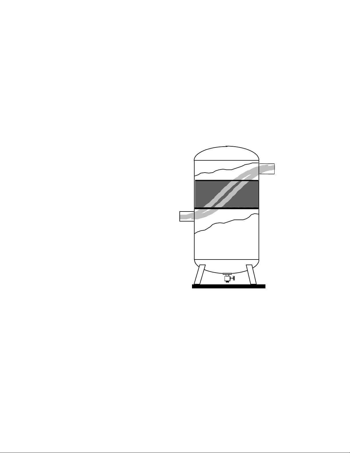
The compressed air is forced through a
drying agent such as dehydrated chalk or
magnesium chloride, which remains in solid
form, or lithium chloride or calcium chloride,
which reacts with the moisture to form a
solution which is drained from the bottom of
the vessel.
Output
The drying agent must be replenished at
regular intervals (2-4 times/year) because the
dew point will increase as the salt is consumed
during operation. A pressure dew point of 50C
at .7 MPa is possible (40 0F at 100 psi).
The main advantages of this method are
that it is of low initial and operating cost. The
disadvantages are that the inlet temperature
must not exceed 300C (860 F), the chemicals
involved are highly corrosive necessitating
carefully monitored filtering to ensure that a
fine corrosive mist is not carried over to the
pneumatic system, and the spent chemical
must be properly disposed of, which is
becoming increasingly costly.
Input
Fig. 4.10 Principle of the Absorption Air Dryer
DO NOT COPY WITHOUT WRITTEN PERMISSION – 30 –
Page 37
Ad s orp t ion (d e sic c ant ) Dr y i ng
Exhaust
Output Dry Air
Input Wet Air
Column 1
(working)
Column 2
(regenerating)
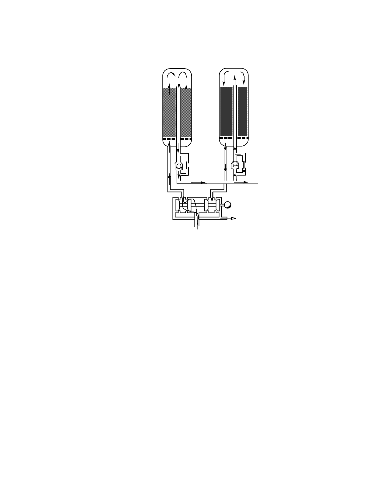
A chemical such as silica
gel or activated alumina in
granular form is contained in a
vertical chamber to physically
adsorb moisture from the
compressed air passing
through it. Adsorption is a
physical process of a liquid
adhering to the surface of
certain materials (a sponge
absorbs, retaining moisture
internally --- adsorb is a
surface effect, think “adhere”).
When the drying agent
becomes saturated it is
regenerated by drying,
heating, or, by a flow of
previously dried air as in Fig.
4.11.
Wet compressed air is
supplied through a directional
control valve and passes
through desiccant column 1.
The dried air flows to the outlet
port. Between 10-20% of the
dry air passes through orifice
O2 and column 2 in reverse
direction to re-adsorb moisture
from the desiccant to regenerate it.
P N E U M A T I C T E C H N O L O G Y
O1
Fig. 4.11 Principle of the Adsorption Air Dryer
O2
The dry air enters the saturated chamber and expands (dropping the temperature further, making the dry air
effectively even more dry to facilitate the regenerating process). The regenerating airflow goes then to exhaust. A
timer or sensor periodically switches the directional control valve to alternately direct the supply air to one column
while regenerating the desiccant in the other, thus providing continuous dry air.
Extremely low dew points are possible with this method, for example - 40oC (which is, oddly enough, -40 0F).
A color indicator may be incorporated in the desiccant to monitor the degree of saturation. Micro-filtering is
essential before the dryer inlet to prevent contamination of the adsorbent, and recommended on the dryer outlet
to prevent carry over of adsorbent mist. Initial and operating costs are comparatively high, but maintenance costs
tend to be low.
DO NOT COPY WITHOUT WRITTEN PERMISSION – 31 –
Page 38
P N E U M A T I C T E C H N O L O G Y
Ref rig e ran t dr y ing
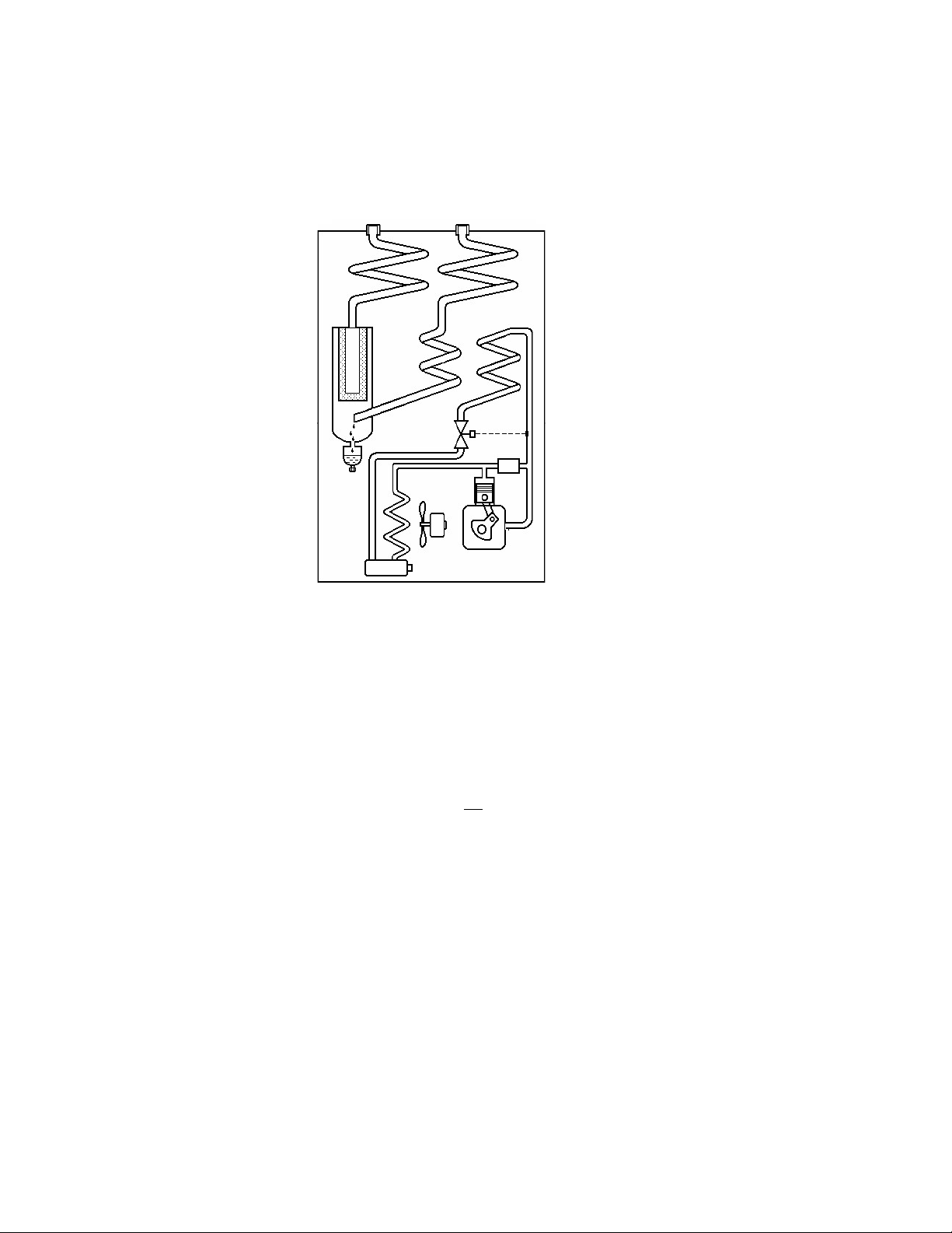
This is a mechanical unit incorporating a refrigeration circuit and two heat exchangers.
Humid high temperature
air is pre-cooled in the first
heat exchanger by
transferring part of its heat to
the cooled output air.
Dry Air OUT Hot Air IN
Heat Exchanger:
input air / output air
It is then cooled by the
refrigerator principle of heat
extraction as a result of
evaporating Freon (not any
more, however) gas in the
refrigerator circuit, in heat
exchanger. At this time,
moisture and oil mists
condense and are
automatically drained.
The cold dry air return pipe
passes through air heat
exchanger and gains heat
from the incoming high
temperature air. This
prevents dew forming on the
discharge outlet, increases
volume and lowers relative
humidity.
An output temperature of usually 30C (370 F) is possible by modern methods, although an output air
temperature of 50C is sufficient for most common applications of compressed air. Inlet temperatures may be up to
600C (1400 F) but it is more economical to pre-cool the air to run at lower inlet temperatures. Refrigerant dryers
have a pressure dew point of 30 C at .7 MPa (-21 at P
As a general rule, the cost of drying compressed air may be 10-20% of the cost of compressing air.
>
Fig. 4.12 Principle of the Refrigerated Air Dryer
).
atm
Heat Exchanger or Evaporator:
input air / freon
Freon cooler or Condensor
Condensor Fan(for 3)
Compressor for Freon
Thermostatic valve
Air filter
Auto Drain
The cost of not drying compressed air is seen in increased maintenance of all pneumatic components used in
the system, plus the associated increased downtime, far exceeding the costs of adding a drying system.
DO NOT COPY WITHOUT WRITTEN PERMISSION – 32 –
Page 39
P N E U M A T I C T E C H N O L O G Y
Mem b ran e Ai r Dry e r
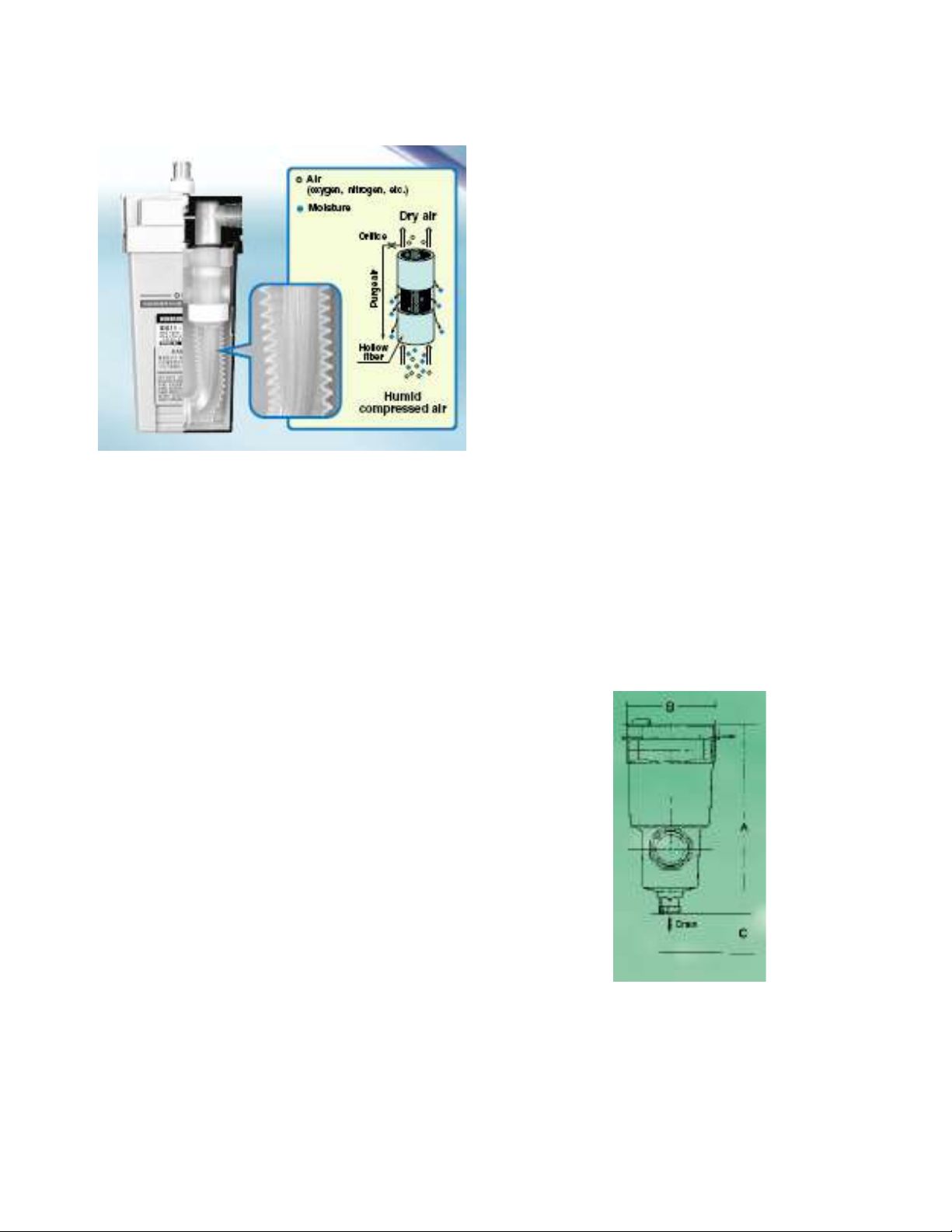
The membrane air dryer uses hollow fibers composed
of a macro molecular membrane through which
moisture passes easily, but which is difficult for air
(oxygen and nitrogen) to pass through.
When humid, compressed air is supplied to the inside
of the hollow fibers, only moisture permeates the
membrane and moves to the outside due to the
pressure difference between the moisture
inside and outside of the fibers. The compressed air
becomes dry air and continues out of the dryer. Part of
the dry air from the outlet side is passed through a very
small orifice to reduce the pressure and purge the
outside of the hollow fibers. The moisture, which
permeated to the outside of the hollow fibers, is
discharged to the atmosphere by this purge air. In this
way, the partial pressure outside of the hollow fibers
remains low and dehumidification is continuously
Fig. 4.13 A typical Membrane Air Dryer
Membrane air dryers are parts that require no electricity, so wiring is not necessary. They are also light-weight
and compact. No coolant is used as in refrigerated units, and no heat or vibration is generated. A dew point
indicator is provided in the membrane air dryer which indicates, by a change of color, that the dew point has been
reached.
performed.
Note: The minimum dew point can be as low as -60C (-760 F). Micro-filtering on the inlet is essential to
prevent clogging of the membrane.
Wat e r r e mov a l f ilt e r
A water removal filter will remove liquid water that is
present in the airline. A water removal filter should be
installed at the point of highest pressure as far from the
compressor as possible. Particle and oil filters, plus
pressure regulation if required, should be installed
downstream of the water removal filter. Because of its
open weave resin mesh element, pressure drop across
a water removal filter is negligible and element
replacement is rarely required.
Water removal filters are typically installed as a back-up
filter in the event of a dryer malfunction, or in place of a
drying system when humid air is acceptable as long as
it contains no liquid water.
Fig. 4.14 A typical Water Removal Filter
DO NOT COPY WITHOUT WRITTEN PERMISSION – 33 –
Page 40
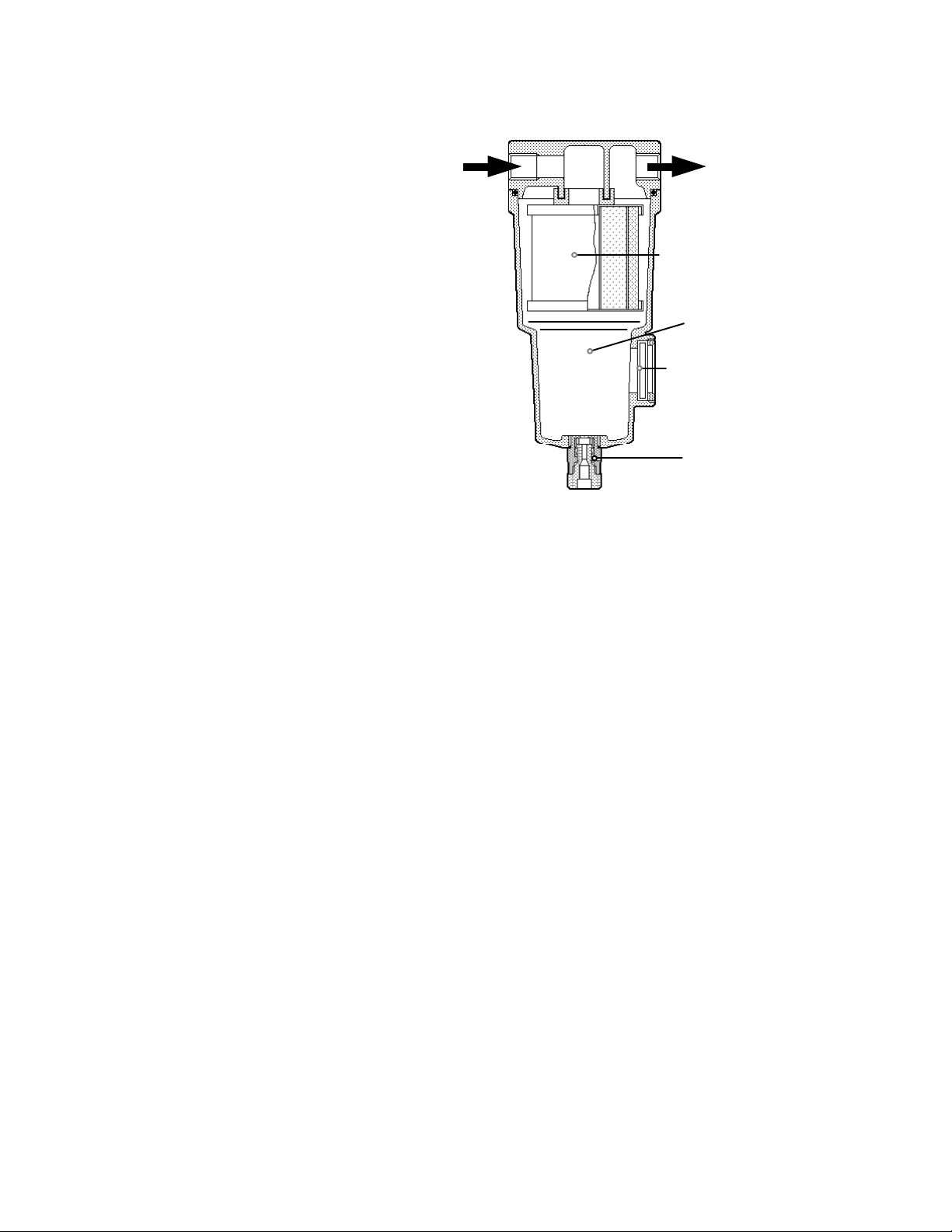
P N E U M A T I C T E C H N O L O G Y
Filter Cartridge
Metal Bowl
Viewing Glass
Drain Valve
Main li ne filte r
A large capacity filter should be installed after
the air receiver to remove contamination, oil
vapors from the compressor, and water from the
air. Proper selection must be sized according to
the system flow. In some cases there are two
main line filters (one in reserve serving as
backup during the filter element change --- which
should be a regularly scheduled maintenance
item).
This filter must have a minimum pressure
drop and the capability to remove oil vapor from
the compressor in order to avoid emulsification
with condensation (seen as a white, milky liquid)
in the line.
It has no deflector, which requires a certain
minimum pressure drop to function properly as
the “Standard Filter” discussed later in the
section on Air Treatment. A built-in or an
attached auto drain will ensure a regular
discharge of accumulated water.
Fig. 4.15 Typical Line Filter
The filter is generally a quick-change cartridge type.
Note that many systems use one main-line filter after the compressor and a mist-separator (micro-filter) after
the drying system, as indicated on page 3.
AI R DISTRIBUT ION
The air main is a permanently installed distribution system carrying the air to the various consumers. Typically
installed at the ceiling level (where the temperatures can be at their highest levels – which fosters entrained
moisture), the air main can be a tremendous source of contamination in the installation process and during normal
use.
During the installation process care must be taken to reduce the metal filings, pipe dope, Teflon tape, and other
foreign materials that will be generated from assembly. The large size of most air mains makes contamination
seem acceptable (a question of relativity at this point), yet when the contamination is seen relative to the extremely
small tolerances in modern automation components (valves, actuators, grippers…) the effect can be disastrous.
If the air main comes in contact with outside air temperatures (connecting two buildings, perhaps being routed
underground, etc.) it will serve as a moisture producer.
As many mains are iron pipe, rust is the eventual by-product. Careful examination should be made when
reusing older pipes to create a new airline. If the opportunity presents itself and a new airline is to be created,
consider the piping configuration as well.
There are two main layout configurations: DEAD END LINE and RING MAIN. After examining 4.16 and 4.17 it
should become apparent that the Ring main configuration would be preferred for better supply flow. The additional
cost is a one-time concern (for the additional pipe) but the advantages can be enjoyed every day of operation.
DO NOT COPY WITHOUT WRITTEN PERMISSION – 34 –
Page 41
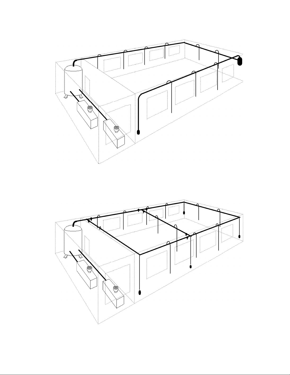
D E AD E N D L I N E
P N E U M A T I C T E C H N O L O G Y
Fig. 4.16 Typical Dead End Line Mains
To assist drainage, the pipe should have a slope of about 1 in 100 in the direction of flow and it should be
adequately drained. At suitable intervals the main can be brought back to its original height by using two long
sweep right angle bends. A drain leg with automatic drain should be installed at each low point.
R I N G M AI N
Fig. 4.17 Typical Ring Main
DO NOT COPY WITHOUT WRITTEN PERMISSION – 35 –
Page 42
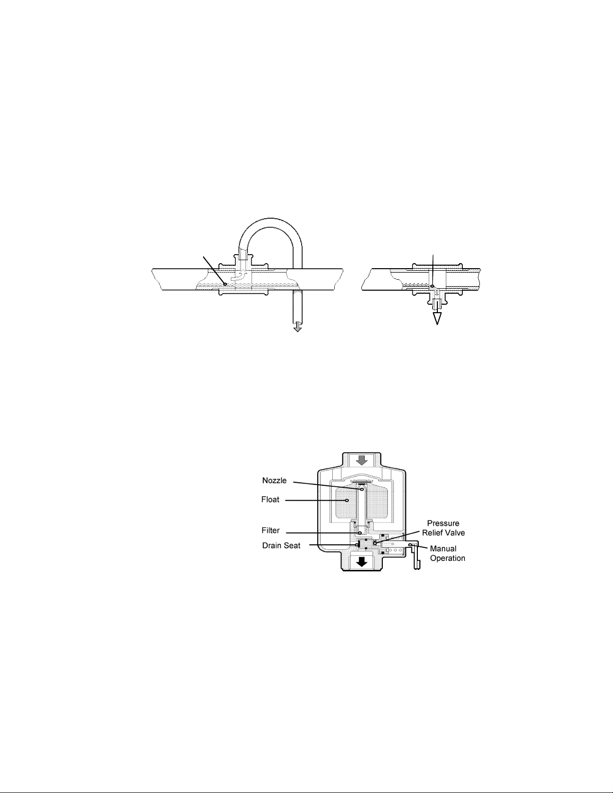
P N E U M A T I C T E C H N O L O G Y
In a ring main system main air can be fed from two sides to a point of high consumption. This will reduce
pressure drop. However this drives condensate in any direction and sufficient water take-off points with Auto
Drains should be provided. Isolating valves can be installed to divide the air main into sections. This limits the area
that will be shut down during periods of maintenance or repair.
S E C O ND A R Y L I N E S
Unless an efficient aftercooler and air dryer are installed, the compressed air distribution pipe acts as a cooling
surface and water and oil will accumulate throughout its length.
Branch lines are taken off the top of the main to prevent water in the main pipe from running into them, instead
of into drainage tubes that are taken from the bottom of the main pipe at each low point of it. These should be
frequently drained or fitted with an automatic drain.
The Water remains
in the Pipe
The Water runs into the
Auto Drain
a b
Fig 4.18 Take-offs for air (a) and Water (b)
Auto drains are more expensive to install initially, but this is offset by the man-hours saved in the operation of
the manual type. With manual draining neglect leads to compound problems due to contamination of the main.
Au t oma t ic D rai n s
Two types of automatic drains are shown in the Figures 4.19 and 4.20.
In the float type of drain. 4.19,
the tube guides the float, and is
internally connected to atmosphere via the filter, a relief valve,
hole in the spring loaded piston
and along the stem of the manual
operator.
The condensate accumulates
at the bottom of the housing and
when it rises high enough to lift
the float from its seat, the
pressure in the housing is
transmitted to the piston which
moves to the right to open the
drain valve seat and expel the
water. The float then lowers to
shut off the air supply to the
piston.
Filter
Nozzle
Float
Drain Seat
Pressure
Relief Valve
Manual
Operation
Fig. 4.19 Float Type Auto Drain
The relief valve limits the pressure behind the piston when the float shuts the nozzle. This pre-set value
ensures a consistent piston re-setting time as the captured air bleeds off through a functional leak in the relief
valve.
DO NOT COPY WITHOUT WRITTEN PERMISSION – 36 –
Page 43
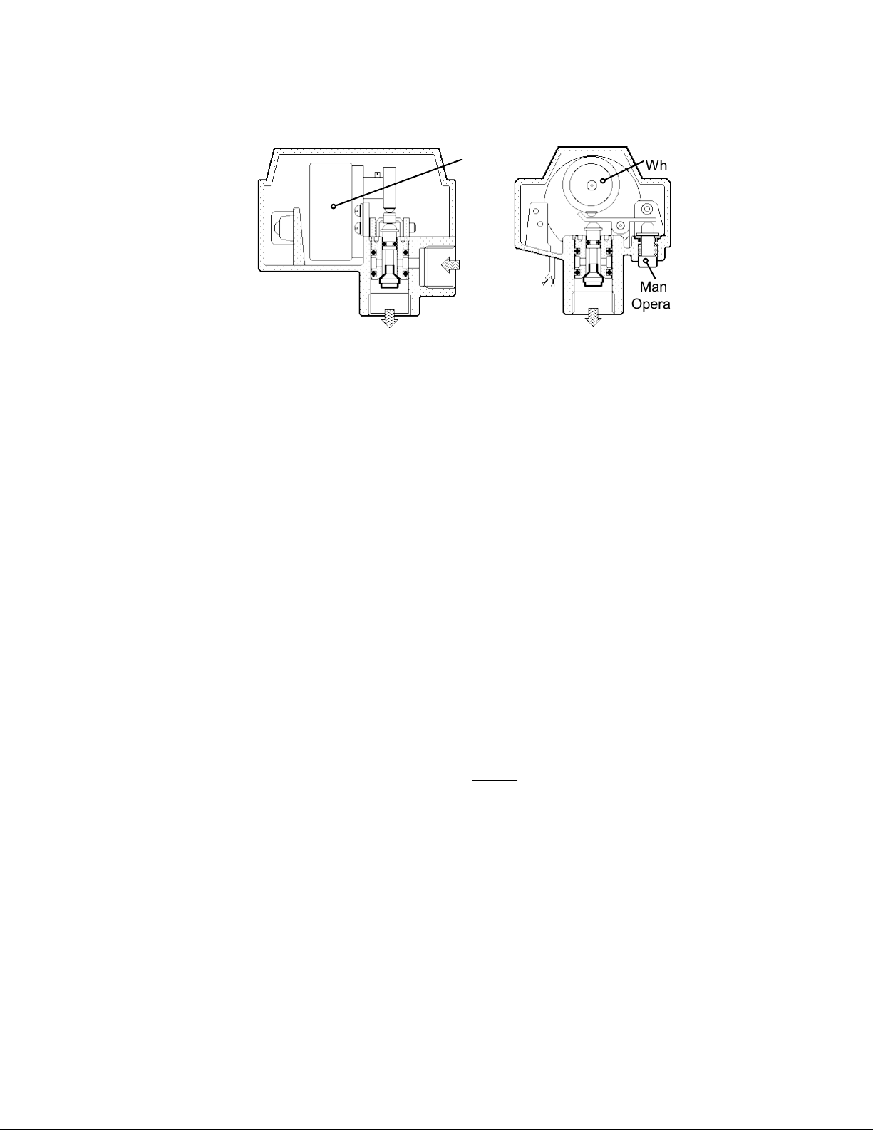
P N E U M A T I C T E C H N O L O G Y
Fig 4.20 shows an electrically driven type, which periodically purges the condensate by a rotating cam wheel
tripping a lever-operated poppet valve.
It offers the advantages of being able to
Synchronous
Motor
Cam
Wheel
work in any orientation
and is highly resistant
to vibration, so lending
itself to use in mobile
compressors, and bus
or truck pneumatic
systems.
Manual
Operation
Fig. 4.20 Motorized Auto Drain
S I Z I N G C O M P R E S S E D A I R M A I N S
The cost of air mains represents a high proportion of the initial cost of a compressed air installation. A
reduction in pipe diameter, although lowering the investment cost, will increase the air pressure drop in the
system; potentially the operating costs will rise and will exceed the additional cost of the larger diameter piping.
Also, as labor charges constitute a large part of the overall cost, and, as this cost varies very little between pipe
sizes, the cost of installing say a 25 mm diameter bore pipe is similar to that of a 50 mm Diameter pipe. But the
flow capacity of the 50mm Diameter pipe will be four times that of 25 mm pipe. This additional volume may equal
two or three (or more) receiver tank volumes, reducing compressor duty cycles.
In a closed loop ring main system, two pipe paths feed the supply for any particular take-off point. When
determining pipe size, this dual feed should be ignored; assuming that at any time air will be supplied through one
pipe only.
The size of the air main and branches is determined by the limitation of the air velocity, normally recommended
at 6 m/s, while sub-circuits at a pressure of around 6 bar and a few meters in length may work at velocities up to
20m/s. The pressure drop from the compressor to the end of the branch pipe should not exceed 30 kPa. The
nomogram (Fig 4.21) allows us to determine the required pipe diameter.
Bends and valves cause additional flow resistance, which can be expressed as additional (equivalent) pipe
lengths in computing the overall pressure drop. Table 4.22 gives the equivalent lengths for the various fittings
commonly used.
Example (a) To determine the size of pipe that will pass 16800 l/min of free air with a maximum pressure drop of
not more than 30 kPain 125 m of pipe. The 2 stage compressor switches on at .8 MPa and stops at 1.0
MPa; the average is .9 MPa.
30 kPa pressure drop in 125 m of pipe is equivalent to
30 kPa
125 m
=0.24 kPa / m.
Referring to Nomogram 4.21: Draw a line from .9 MPa on the pressure line through 0.24 kPa / m on the
pressure drop line to cut the reference line at X.
Join X to 0.28 m
3
/s and draw a line to intersect the pipe size lines at approximately 61 mm.
n
Pipe with a minimum bore of 61 mm can be used. A 65 mm nominal bore pipe (see Table 4.23) has a bore
of 68 mm and would satisfy the requirements with some margin.
DO NOT COPY WITHOUT WRITTEN PERMISSION – 37 –
Page 44

P N E U M A T I C T E C H N O L O G Y
Example (b) If the 125 m length of pipe in (a) above has a number of fittings in the line, e.g., two elbows, two 90°
bends, six standard tees and two gate valves, will a larger size pipe be necessary to limit the pressure drop
to 30 kPa?
In Table 4.22, column “65 mm Diameter”, we find the following equivalent pipe length:
Two elbows: 2· 1.4 m = 2.8 m
Two 90° bends: 2 · 0.8 m = 1.6 m
Six standard tees: 6 · 0.7 m = 4.2 m
Two gate valves: 2 · 0.5 m = 1.0 m
Total 9.6 m
The twelve fittings have a flow resistance equal to approximately 10 m additional pipe length.
The “Effective Length” of the pipe is thus 125 + 9.6 135 m
And the allowed p / m:
Referring again to nomogram in fig 4.21: The pipe size line will now cut at almost the same diameter; a
nominal bore pipe of 65 mm, with an actual inner diameter of 68 mm will be satisfactory.
Note:
The possibility of future air demands should be taken into account when determining the size of main lines for a
new installation. For that matter, compressors, after-coolers, receivers, filters, and dryers should also be sized with
future increased demands in mind. Remember, cheaper only costs less once!
30 kPa
135 m
= 0.22 kPa / m
DO NOT COPY WITHOUT WRITTEN PERMISSION – 38 –
Page 45
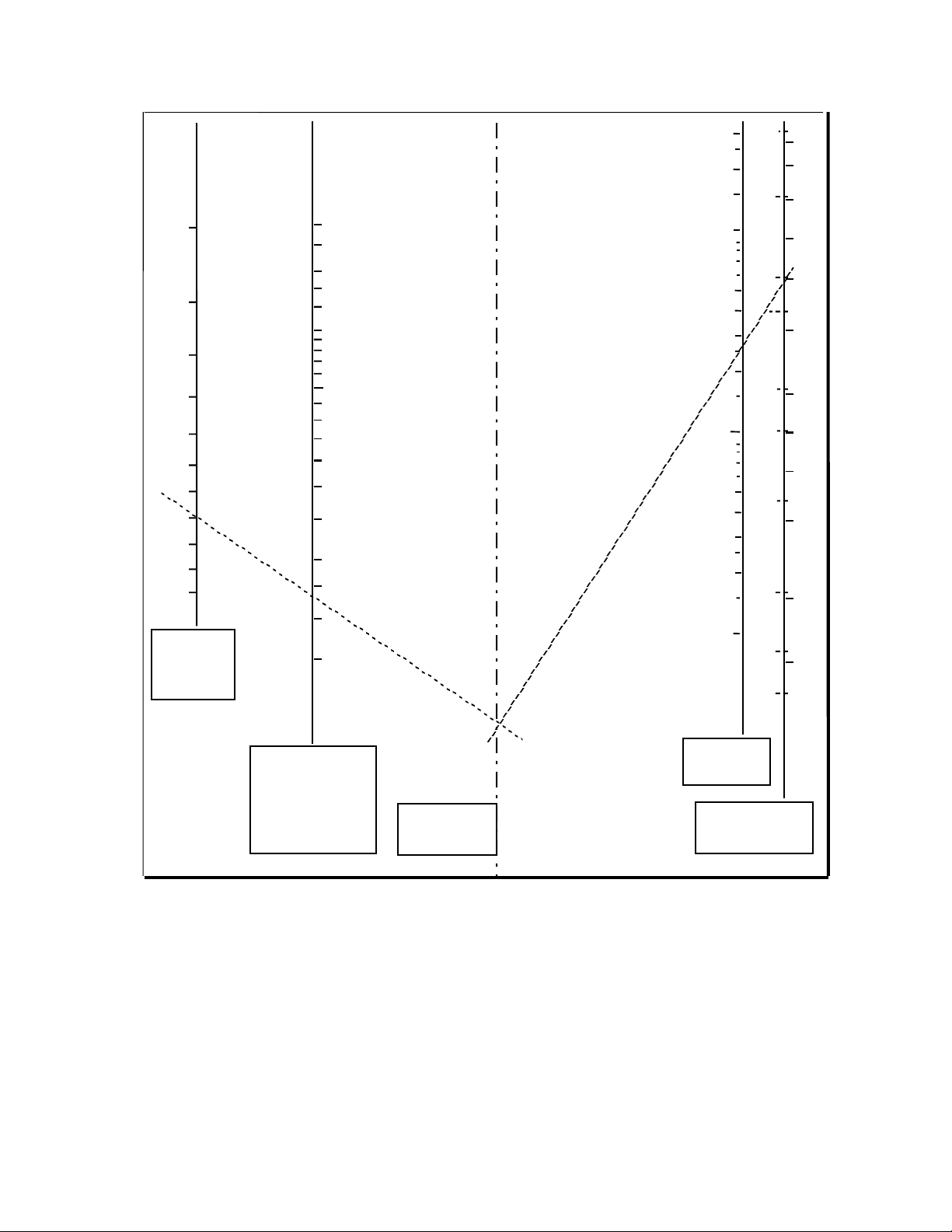
P N E U M A T I C T E C H N O L O G Y
.2
.4
.5
.7
Line
Pressure
(
²p
kPa / m
= bar /100 m
1
70
mm
Reference
3/8"
Q
n
1.5
4"
3
2
3"
100
90
80
3.0
2.5
.3
2.25
2.0
1.75
1.5
0.5
0.4
0.3
2.5"
2"
60
50
0.2
.6
.8
.9
.10
.11
.12
1.0
0.9
0.8
0.7
0.6
0.5
0.4
0.3
0.25
0.15
0.05
0.04
0.03
0.025
0.02
0.015
0.1
1.5"
1.25"
1"
3/4"
40
35
30
25
20
0.2
0.01
0.15
1/2"
15
MPa)
X
Pipe Length
Line
Fig. 4.21 Nomogram for Sizing the Mains Pipe Diameter
3
(m /s
Inner Pipe Dia.
,
DO NOT COPY WITHOUT WRITTEN PERMISSION – 39 –
Page 46
P N E U M A T I C T E C H N O L O G Y
Type of Fitting Nominal pipe size (mm)
Elbow
90* Bend (long)
90* Elbow
180* Bend
Globe Valve
Gate Valve
Standard Tee
Side Tee
Table 4.22 Equivalent Pipe Lengths (meters) for the main fittings
Mate r ial s fo r Pi p in g
Traditionally, any conductor that is threaded is referred to as a pipe; others would be either tube or hose.
Sta n dar d Ga s Pi p e ( S GP)
The air main is usually a steel or malleable iron pipe. This is obtainable in black or galvanized form, which is
less liable to corrode. This type of piping can be screwed to accept the range of proprietary malleable fittings. For
over 80 mm Diameter, welded flanges are often more economical to install rather than cut threads into large pipes.
The specifications of the Carbon Steel Standard Gas Pipe (SGP) are:
100 4 114.3 4.5 12.100
15 20 25 30 40 50 65 80 100 125
0.3 0.4 0.5 0.7 0.8 1.1 1.4 1.8 2.4 3.2
0.1 0.2 0.3 0.4 0.5 0.6 0.8 0.9 1.2 1.5
1.0 1.2 1.6 1.8 2.2 2.6 3.0 3.9 5.4 7.1
0.5 0.6 0.8 1.1 1.2 1.7 2.0 2.6 3.7 4.1
0.8 1.1 1.4 2.0 2.4 3.4 4.0 5.2 7.3 9.4
0.1 0.1 0.2 0.3 0.3 0.4 0.5 0.6 0.9 1.2
0.1 0.2 0.2 0.4 0.4 0.5 0.7 0.9 1.2 1.5
0.5 0.7 0.9 1.4 1.6 2.1 2.7 3.7 4.1 6.4
Nominal Width Outside
Diameter.
A B mm mm kg/m
6 1/8 10.5 2.0 0.419
8 1/4 13.8 2.3 0.652
10 3/8 17.3 2.3 0.851
15 1/2 21.7 2.8 1.310
20 3/4 27.2 2.8 1.680
25 1 34.0 3.2 2.430
32 1 1/4 42.7 3.5 3.380
40 1 1/2 48.6 3.5 3.890
50 2 60.3 3.65 5.100
65 2 1/2 76.1 3.65 6.510
75 3 88.9 4.05 8.470
Thickness Mass
T a ble 4.2 3 Pi p e Si ze Spe cifi cat io n
Sta i nle s s s t eel pip e s
These are primarily used when very large diameters in long straight main lines are required.
Cop p er Tube
Where corrosion, heat resistance and high rigidity are required, copper tubing up to a nominal diameter of 40
mm can be used, but will be relatively costly over 28-mm. diameter. Compression fittings used with annealed
quality tubing provide easy working for installation.
DO NOT COPY WITHOUT WRITTEN PERMISSION – 40 –
Page 47
P N E U M A T I C T E C H N O L O G Y
Rub b er Tube (“ A ir H ose ” )
Rubber hose or reinforced plastic is most suitable for air actuated hand tools as it offers flexibility for freedom
of movement for the operator. The dimensions of Pneumatic Rubber Hose are:
Nominal Width,
inches
Outside
Diameter. Mm
Inside Dia.
mm
Inner Sectional Area
mm2
1/8 9.2 3.2 8.04
1/4 10.3 6.3 31.2
3/8 18.5 9.5 70.9
1/2 21.7 12.7 127
5/8 24.10 15.9 199
3/4 29.0 19.0 284
1 35.4 25.4 507
1 1/4 45.8 31.8 794
1 1/2 52.1 38.1 1140
1 3/4 60.5 44.5 1560
2 66.8 50.8 2030
2 1/4 * 81.1 57.1 2560
2 1/2* 90.5 63.5 3170
Table 4.24 Rubber hose Specification* Cloth-wrapped hose
*Rubber hose is mainly recommended for tools and other applications where the tube is exposed to
mechanical wear.
Pla s tic tub i ng
Plastic tubing is commonly used for the interconnection of pneumatic components. Within its working
temperature limitations it has obvious advantages for installation, allowing easy cutting to length, and rapid
connection by either compression or quick-fit fittings.
If greater flexibility for tighter bends or constant movement is required, softer grades of nylon or polyurethane
are available, but may have lower maximum safe working pressures. Be aware that plastic tubing is sized by its
Outside Diameter (OD), not its Internal Diameter (ID). For example, a ¼” tube has a typical I.D. of only 0.125”.
DO NOT COPY WITHOUT WRITTEN PERMISSION – 41 –
Page 48
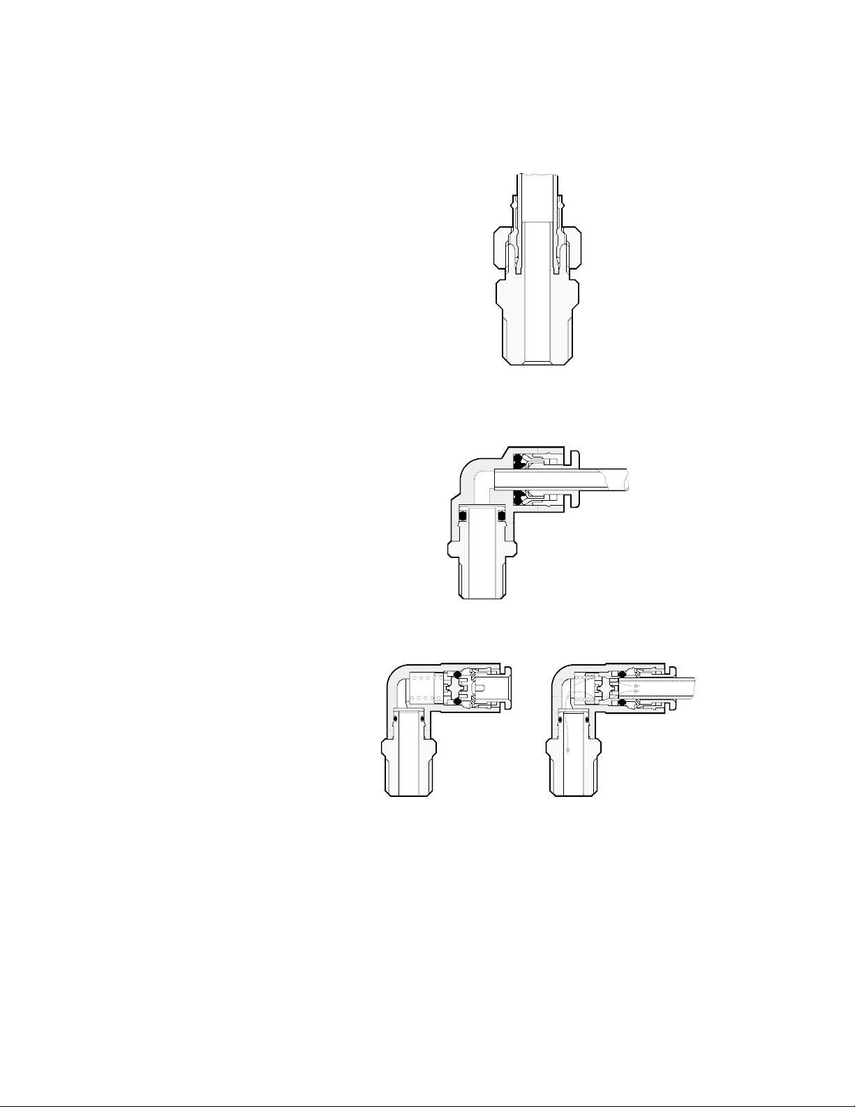
P N E U M A T I C T E C H N O L O G Y
Fi t tin g s i n Sy s tem s
In systems, pneumatic components are connected by various methods.
The INSERT type provides a reliable
retaining force inside and outside of the
tube. The tube is pressed by the sleeve
when screwing in the cap nut. The tube
(insert) entering into the tube reduces its
inner diameter and thus represents a
considerable extra flow resistance.
Insert sleeves are not reusable.
The PUSH - IN connection has a large
retaining force and the use of a special
profile seal ensures positive sealing for
pressure and vacuum. There is no additional
flow restriction, as the connection has the
same inner flow section as the inner
diameter of the fitting tube.
Reusable for hundreds of insertions.
The SELF-SEALING fitting has a built in
mechanism so that air does not exhaust
after removal of the tube and is also
applicable for copper free applications.
a. If no tube is pushed in, a check
a
valve shuts off the fitting.
When a tube is inserted, it opens
bb
the airflow by pushing the check valve
from its seat. Note that the check valve
creates a restriction to flow, compared to
a standard fitting, so care must be taken
to properly size the fitting.
Fig. 4.25 Example of an Insert Fitting.
Fig. 4.26 Example of a Push-in Fitting, elbow type
a b
Fig. 4.27 Example of a Self-Seal Fitting.
DO NOT COPY WITHOUT WRITTEN PERMISSION – 42 –
Page 49
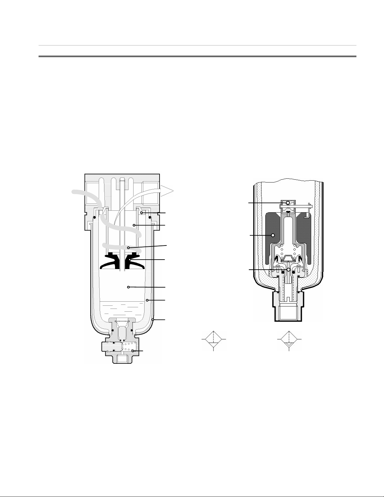
P N E U M A T I C T E C H N O L O G Y
Deflector
Filter Element
Vortex
Baffle Plate
Quiet Zone
Bowl Guard
Drain Valve
Clean Air
Bowl
Pilot Valve
Drain Valve
Float
Symbol
Filter/Separat
or
Symbol Filter/Separator
with Auto Drain
55 AAIIRR TTRREEAATTMMEENNTT
As described previously, all atmospheric air carries both dust and moisture. After compression, moisture
condenses out in the aftercooler and receiver but there will always be some that will be carried over. Moreover
fine particles of carbonized oil, pipe scale and other foreign matter, such as worn sealing material, form gummy
substances. All of this is likely to have injurious effects on pneumatic equipment by increased seal and component
wear, seal expansion, corrosion and sticking valves.
To remove these contaminants, the air should be further cleaned (filtered) as near as possible to the point of
use. Air treatment also includes Pressure Regulation and occasionally Lubrication.
FILTERI NG
S T AN D A R D F IL T E R
The standard filter is a combined water separator and filter. If the air has not been de-hydrated beforehand, a
considerable quantity of water will be collected and the filter will hold back solid impurities such as dust and rust
particles.
The water separation occurs mainly by a rapid rotation of the air, caused by the deflector at the inlet. The
heavier particles of dirt, water and oil are thrown outwards to impact on the wall of the filter bowl before running
down to collect at the bottom. The liquid can then be drained off through a manual drain cock or an automatic
drain. The baffle plate creates a quiet zone beneath the swirling air, preventing the separated liquid from being reentrained into the air stream.
Fig. 5.1 Typical Filter/Water Separator and an Automatic Drain as option
DO NOT COPY WITHOUT WRITTEN PERMISSION – 43 –
Page 50
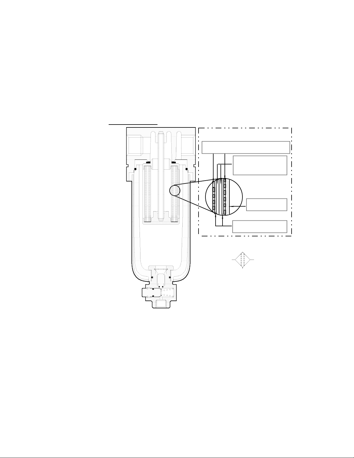
P N E U M A T I C T E C H N O L O G Y
The filter element removes the finer particles of dust, rust scale and carbonized oil as the air flows through to
the outlet. The standard element will remove all contamination particles down to 5 microns in size. Some
elements can be easily removed, cleaned and re-used a number of times before needing to be replaced because
of excessive pressure drop.
The bowl is typically made from polycarbonate. For safety a metal bowl guard must protect it. For chemically
hazardous environments special bowl materials must be used. If the bowl is exposed to heat, sparks, etc, a metal
bowl should be used.
If the condensate accumulates at a high rate it is desirable to provide automatic draining.
The right hand side of Fig. 5.1 shows a float type of auto drain unit built-in for standard filters.
M I C R O F I L T E R S O R C O AL E S C E R S – (sometimes referred to as Mist Separators)
Where contamination by
oil vapor is undesirable, a
micro-filter is used. Being a
pure filter it is not equipped
with a deflector plate.
The air flows from the
inlet to the center of the
filter cartridge then outwards through the outlet.
Dust is trapped within the
micro filter element. The oil
vapor and water mist is
converted into liquid by a
coalescing action within the
filter material, forming drops
on the filter cartridge to
collect at the bottom of the
bowl. Approximately 99% of
oil mist can be removed.
Cartridge
Perforated Stainless Steel Plate
Filtering Tissue
0.3 µm
PVC Sponge
Filter Paper, 4µm
ISO Symbol
Multistage Filter
S U B - M I CR O F I L T E R S
electrostatic spray painting, cleaning and drying of electronic assemblies etc --- the principle of operation is the
same as a micro filter, but its filter element has additional layers with a higher filtration efficiency.
F I L T E R S EL E C T I O N
The size of air filter that is required for a particular application is dependent on two factors: -
a) The maximum flow of compressed air used by the pneumatic equipment.
b) The maximum acceptable pressure drop for the application.
Manufacturers provide flow/pressure diagrams to enable correct sizing to be done.
It should be noted that standardizing on one large filter for every application might result in water not being
separated as efficiently due to the lower flow velocity resulting from using a larger filter.
DO NOT COPY WITHOUT WRITTEN PERMISSION – 44 –
Page 51
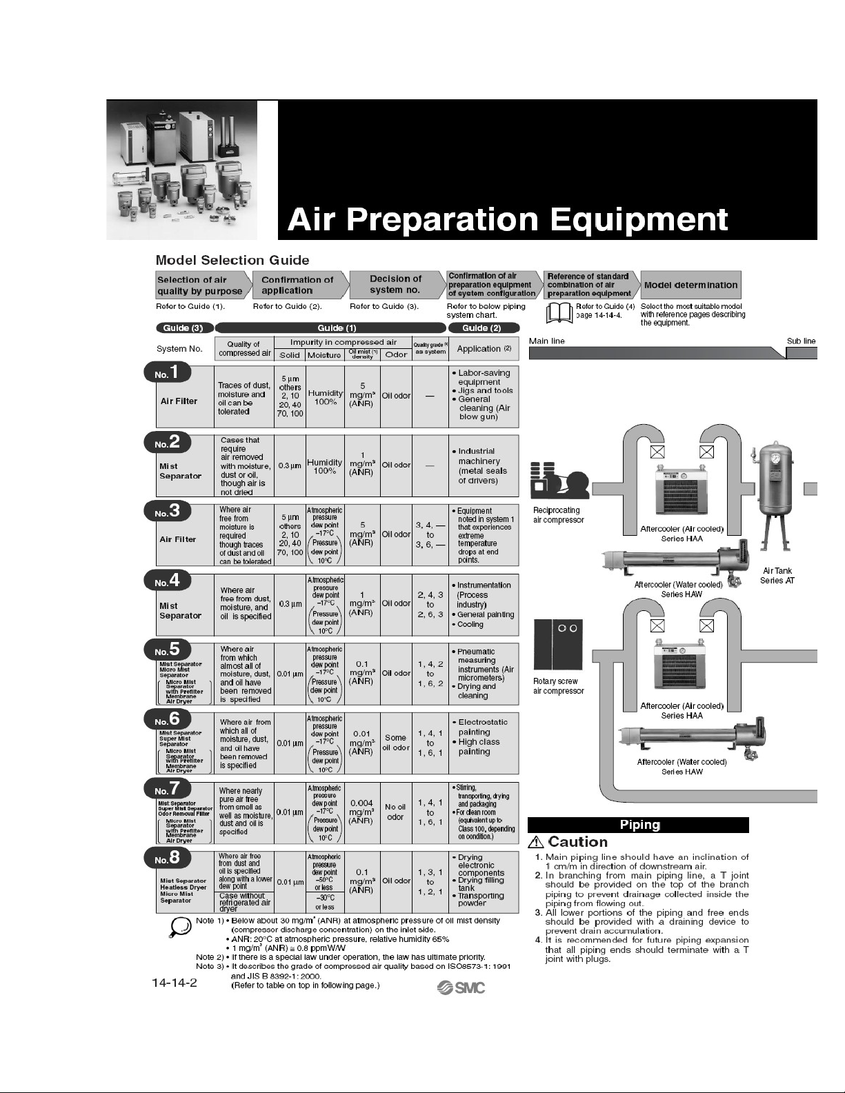
P N E U M A T I C T E C H N O L O G Y
DO NOT COPY WITHOUT WRITTEN PERMISSION – 45 –
Page 52
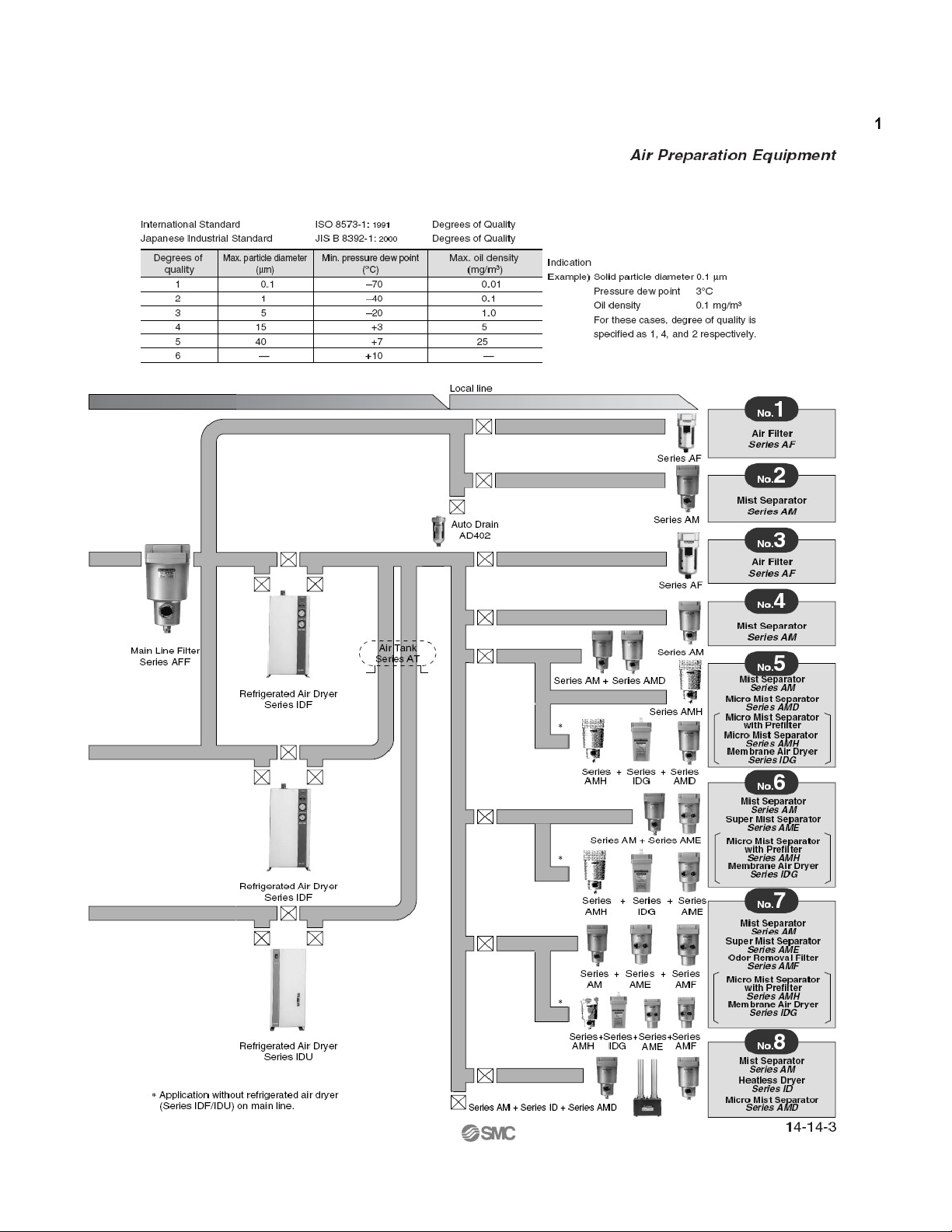
P N E U M A T I C T E C H N O L O G Y
DO NOT COPY WITHOUT WRITTEN PERMISSION – 46 –
Page 53
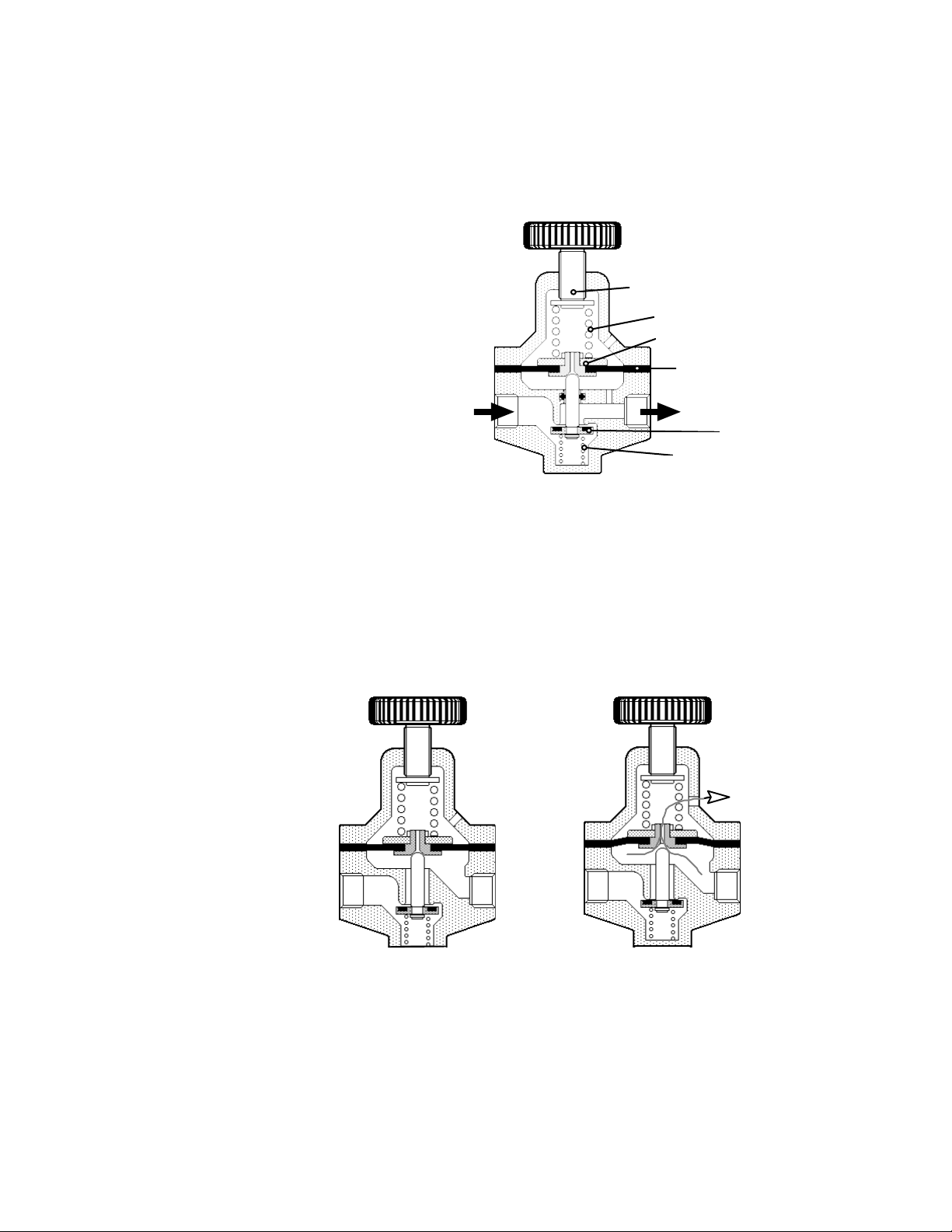
P N E U M A T I C T E C H N O L O G Y
Relieving
p1p
2
PRE SSUR E RE GUL ATI ON
Regulation of pressure is necessary because at pressures above optimum, rapid wear will take place with little
or no increase in output. Air pressure that is too low is uneconomical because it results in poor efficiency.
S T AN D A R D R EG U L A T OR
Pressure regulators have a piston or
diaphragm to balance the output pressure
against an adjustable spring force.
The secondary pressure is set by the
adjusting screw loading the setting spring to
hold the main valve open, allowing flow from
the primary pressure p1 inlet port to the
secondary pressure p2 outlet port. Then the
pressure in the circuit connected to the outlet
rises and acts on the diaphragm, creating a
lifting force against the spring load.
When consumption starts, p2 will initially
drop and the spring, momentarily stronger
than the lifting force from p2 on the
diaphragm, opens the valve.
If the consumption rate drops, p2 will slightly increase, this increases the force on the diaphragm against the
spring force --- diaphragm and valve will then lift until the spring force is equaled again. The airflow through the
valve will be reduced until it matches the consumption rate and the output pressure is maintained.
p1
Fig 5.5. Principle of the Pressure Regulator
Adjusting Knob
Adjusting Spindle
Setting Spring
Diaphragm Disc
Diaphragm
p2
Valve
Valve Spring
If the consumption rate increases, p2 will slightly decrease. This decreases the force on the diaphragm against
the spring force, diaphragm and valve drop until the spring force is equaled again. This increases the airflow
through the valve to match the consumption rate.
Without air consump-
tion the valve is closed. If
the secondary pressure
rises above the set value
by virtue of:
• re-setting the
regulator to a lower outlet
pressure, or
• an external reverse
thrust from an actuator,
the diaphragm will lift to
open the relieving seat so
that excess pressure can
be bled off through the
vent hole in the regulator
body.
Do NOT rely on this
orifice as an exhaust flow
path.
a
Fig. 5.6 Relieving Function
b
DO NOT COPY WITHOUT WRITTEN PERMISSION – 47 –
Page 54
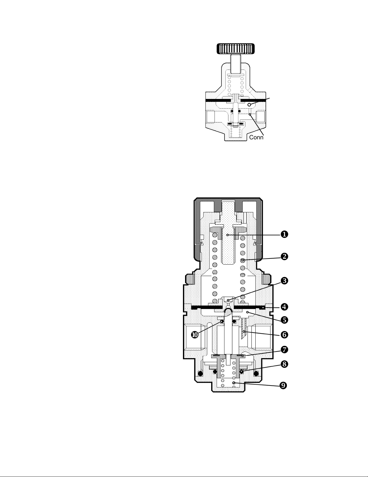
P N E U M A T I C T E C H N O L O G Y
Flow Compensated Regulator (Q-
Compensation)
With very high flow rates the valve is wide
open. The spring is therefore elongated and thus
weaker and the equilibrium between p2 on the
diaphragm area and the spring occurs at a lower
level. This problem can be corrected by creating a
third chamber with a connection to the output
channel. In this output channel the flow velocity is
high. As explained in section 3, the static pressure
is then low (Bernoulli). As p3 is now at a lower
static pressure, the balance against the weakened
spring at high flow rates is compensated, thus
allowing the valve to remain open longer.
The effect can be improved by inserting a tube
in the connection, cut at an angle with the opening
oriented towards the outlet (Fig 5.8). The angled
tube creates a venturi effect, thus lowering the
pressure at p3 even more as a way to compensate
for high flow rates.
p3
p1 p2
Connection
Fig. 5.7 Principle of a Flow Compensated
Regulator
Pressure Compensation
There is still an inconvenience in the regulator
of Fig. 5.7: if the inlet pressure p1 increases, a
higher force is acting on the bottom of the valve,
trying to close it. That means that an increasing
input pressure decreases the output pressure and
vice versa. A valve having equal surface areas for
both input and output pressure in both directions
can eliminate this. This is realized in the regulator
of Fig. 5.8
The most important parts are:
Adjusting Spindle
Setting Spring
Relieving Seat
Diaphragm
Flow Compensation Chamber
Flow Compensation Connection Tube
Valve
O-Ring for Pressure Compensation
Valve Spring
O-Ring for Flow Compensation
DO NOT COPY WITHOUT WRITTEN PERMISSION – 48 –
Fig. 5.8 Fully compensated Pressure Regulator
Page 55
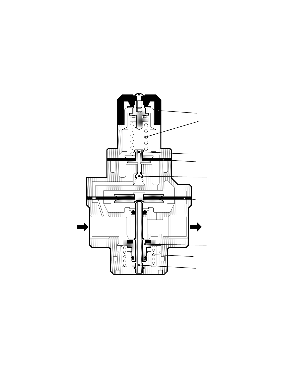
P N E U M A T I C T E C H N O L O G Y
Adjusting Knob
Pilot Pressure Relief
Setting Spring
Main Diaphragm
Pilot Valve
Main Valve
Main Secondary
Pressure Relief
Pilot
p 1 p 2
P I L O T O P ER A T E D R E G U L A T OR
The pilot operated regulator offers greater accuracy of pressure regulation across a large flow range.
This accuracy is obtained by replacing the setting spring of a standard regulator with pilot pressure from a
small pilot regulator sited on the unit.
The pilot regulator on top of the unit supplies or exhausts pilot air only during corrections of the output
pressure. This enables the regulator to achieve very high flow rates but keeps the setting spring length to a
minimum.
Main Valve
Fig 5.9 Pilot Pressure Regulator
DO NOT COPY WITHOUT WRITTEN PERMISSION – 49 –
Page 56
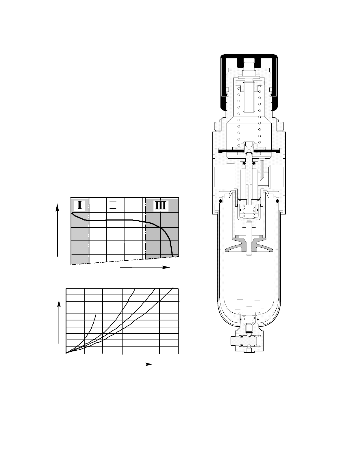
P N E U M A T I C T E C H N O L O G Y
further
.5
.4
2000
0
4000
6000
1
0
.1 MPa
(l /min)
Q
(MPa)
F I L T E R - R EG U L A T O R
Air filtering and pressure regulation is combined in the
single filter regulator to provide a compact space saving unit.
Siz ing of R eg u lat o rs a nd F ilt ers
A regulator size is selected to give the flow required by the
application with a minimum of pressure variation across the
flow range of the unit.
Manufacturers provide graphical information regarding the
flow characteristics of their equipment. The most important is
the Flow / p2 diagram. It shows how p2 decreases with
increasing flow. (Fig. 5.11). The curve has three distinct
portions:
1. The inrush, with a small gap on the valve that does not
yet allow real regulation
2. The regulation range and
3. The saturation range; the valve is wide open and
regulation is impossible
p 2
(MPa)
.8
II
.7
.6
a
²p
Q (l/min)
.3 MPa
.5 MPa
0.05
b
Fig. 5.11 Typical Flow/Pressure Characteristics:
a: Regulator, b: Filter
.7 MPa
Fig 5.10 Typical Filter Regulator
DO NOT COPY WITHOUT WRITTEN PERMISSION – 50 –
Page 57

P N E U M A T I C T E C H N O L O G Y
FRL elements have to be sized in accordance with the required flow capacity. For Regulators, the average
volume flow should be the one in the middle of the regulating range (II in fig.5.11 a). The pressure drop also
defines the size of the filter. For a “Standard Filter/Separator" (not a Line Filter), a minimum pressure drop of about
0.02 MPa (3 psi) is required to ensure functioning. With maximum flow, Æp (allowable or desirable delta p)
should however be kept between .02 – .06 MPa (3 – 7 psi).
The size is therefore defined by the required flow, not by the connection size of the component. Modular
systems give the capability to adapt the connection thread to the available tube size.
COMP RES SED AI R LU BRICAT ION
Lubrication is no longer a necessity. The vast majority of modern pneumatic components is now available
permanently lubricated, and will operate reliably with no additional lubrication.
The life and performance of these components is fully up to the requirements of modern high cycling process
machinery.
The advantages of "non-lube" systems include:
a) Savings in the cost of lubrication equipment, lubricating oil and maintaining oil levels.
b) Cleaner more hygienic systems; of particular importance in food and pharmaceutical industries.
c) Oil free atmosphere, for a healthier, safer working environment.
Certain equipment still requires lubrication. To ensure they are continually lubricated, a certain quantity of oil is
added to the compressed air by means of a lubricator.
P R O P O RT I O N A L L UB R I C A T OR S
In a (proportional) lubricator a pressure drop between inlet and outlet, directly proportional to the flow rate, is
created and lifts oil from the bowl into the sight feed dome.
With a fixed size of restriction, a greatly increased flow rate would create an excessive pressure drop and
produce an air/oil mixture that had too much oil, flooding the pneumatic system.
Conversely a decreased flow rate may not create sufficient pressure drop resulting in a mixture that is too lean.
To overcome this problem, lubricators must have self-adjusting cross sections to produce a constant mixture.
Air entering a lubricator (as shown in Fig 5.12) follows two paths: it flows over the damper vane to the outlet
and also enters the lubricator bowl via a check valve.
When there is no flow, the same pressure exists above the surface of the oil in the bowl, in the oil tube and the
sight feed dome. Consequently there is no movement of oil.
When air flows through the unit, the damper vane restrictor causes a pressure drop between the inlet and
outlet. The higher the flow, the greater the pressure drop.
Since the sight feed dome is connected by the capillary hole to the low-pressure zone immediately after the
damper vane, the pressure in the dome is lower than that in the bowl.
This pressure difference forces oil up the tube, through the oil check valve and flow regulator into the dome.
Once in the dome, the oil seeps through the capillary hole into the main air stream in the area of the highest air
velocity. The oil is broken up into minuscule particles, atomized and mixed homogeneously with the air by the
turbulence in the vortex created by the damper vane.
DO NOT COPY WITHOUT WRITTEN PERMISSION – 51 –
Page 58
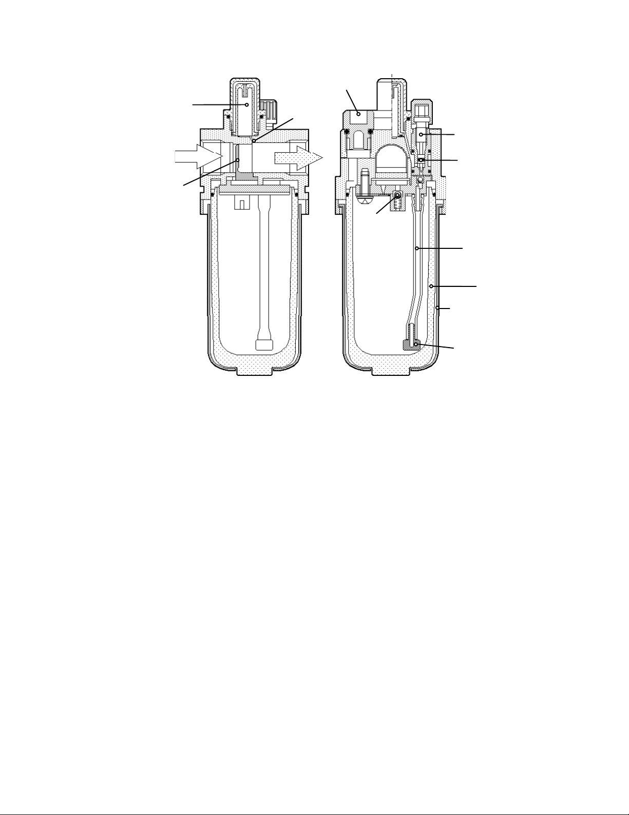
P N E U M A T I C T E C H N O L O G Y
Oil Check Valve
Oil Tube
Sight Feed Dome
Refill Plug
Capillary
Connection
Air
Check
Valve
Damper Vane
Oil Throttle
Bowl
Bowl Guard
Sintered Bronze
Oil Filter
Fig 5.12 Proportional Lubricator
The damper vane is made from a flexible material to allow it to bend as flow increases, widening the flow path,
to proportionally adjust the pressure drop and thus maintain a constant mixture throughout.
The oil throttle allows adjustment of the quantity of oil for a given pressure drop. The oil check valve retains the
oil in the upper part of the tube when the airflow temporarily stops.
The air check valve allows the unit to be refilled under pressure, while work can normally go on.
The correct oil feed rate depends on operating conditions, but a general guide is to allow one or two drops per
cycle of the machine.
A pure (no-additives) mineral oil of 32 centi-stokes viscosity is recommended (ISO standard VG32). Some oil
companies have special oil for compressed air lubrication, with a high capacity to absorb moisture without loss of
lubricating properties.
DO NOT COPY WITHOUT WRITTEN PERMISSION – 52 –
Page 59
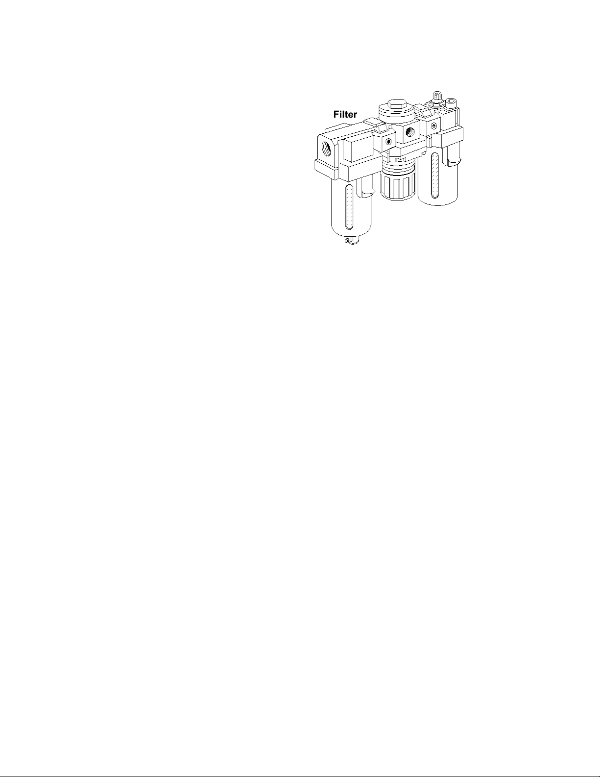
F.R. L. UNIT S
P N E U M A T I C T E C H N O L O G Y
Lubricator
Regulator
Modular filter, pressure regulator and lubricator
elements can be combined into a service unit by
joining with spacers and clamps. Mounting
brackets and other accessories can be easily fitted
in more recent designs.
S I Z E AN D I N S T A L L AT IO N
The combination unit must again be sized for
the maximum flow rate of the system.
Manufacturers will generally provide this
information.
Most systems require an approved shut-off or
lock out valve. In addition, there are devices that
allow an Emergency Stop function and a slow start
option, where air is introduced to the system at a
reduced rate.
For correct placement and operation of these devices consult the manufacturers’ instructions. For maintenance
there should be a way to stop airflow after the F.R.L. unit and before the unit, isolating the F.R.L. for repair. In most
cases, the Emergency Stop should be downstream of the F.R.L. to prevent backflowing (reverse flow) the filter
(which could cause element collapse), the regulator (diaphragm could be damaged), and the lubricator (driving oil
mist inside the filter element).
Fig. 5.13 Typical FRL Unit in a modular design
Filter
DO NOT COPY WITHOUT WRITTEN PERMISSION – 53 –
Page 60
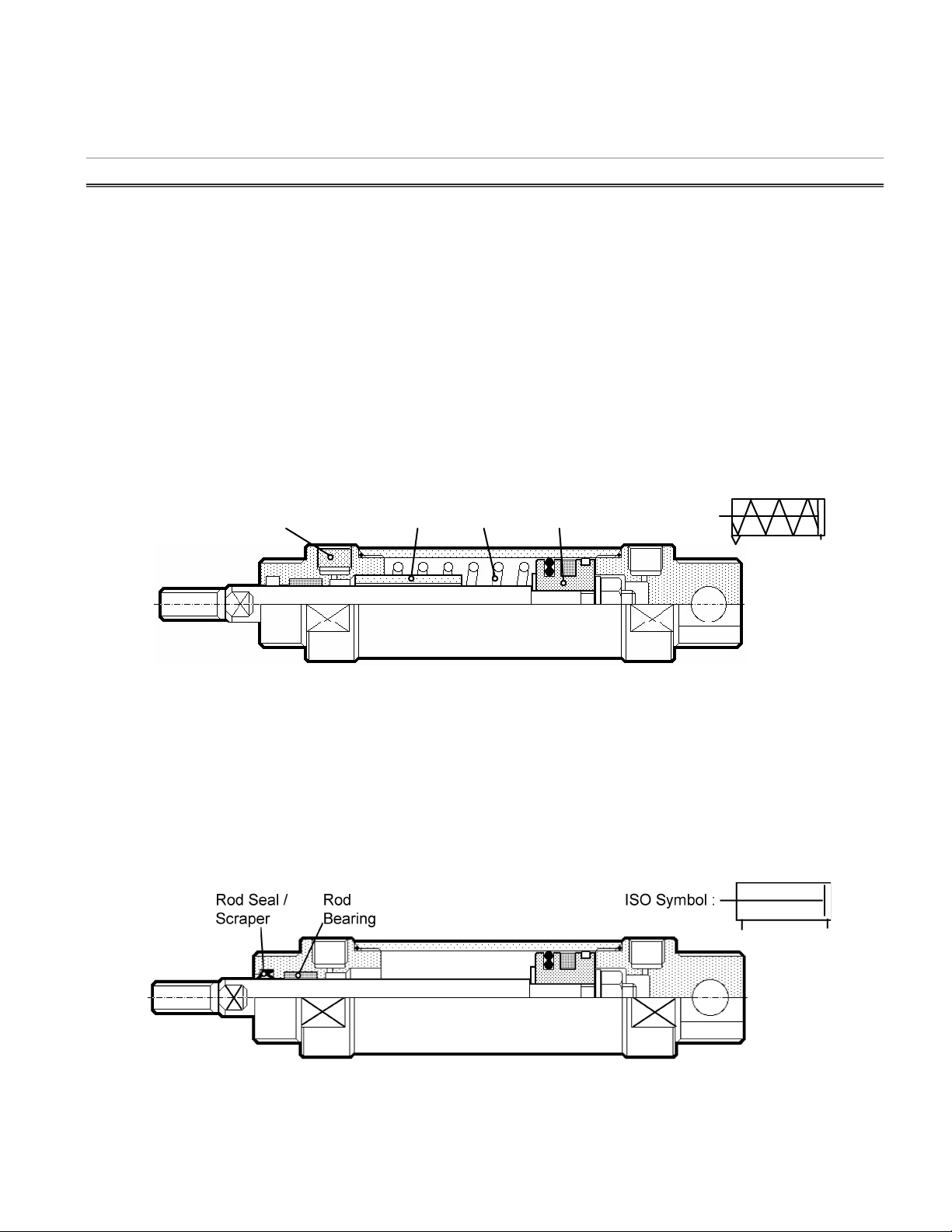
P N E U M A T I C T E C H N O L O G Y
Stop
Spring
Sintered Bronze Filter
Piston
ISO Symbol :
66 AACCTTUUAATTOORRSS
The work done by pneumatic actuators can be linear or rotary. Piston cylinders provide linear movement. Vane
type or rack and pinion type rotary actuators typically produce reciprocating rotary motion up to 270°. Air motors
are used for continuous rotation.
LINE AR CY LIND ERS
Pneumatic cylinders of varying designs are the most common power components used in pneumatic
automation. There are two basic types from which special constructions are derived:
• Single-acting cylinders with one air inlet to produce a power stroke in one direction
• Double-acting cylinders with two air inlets to produce extending and retracting power strokes
S I N G L E A C T IN G C Y L I N D E R
A single acting cylinder develops thrust in one direction only. The piston rod is returned by a fitted spring or by
external force from the load or spring.
It may be a "push" or "pull" type (Fig 6.1)
Fig. 6.1 Typical Single Acting Cylinder, Spring Retracted or “Push” type
Single acting cylinders are used for clamping, marking, ejecting etc. They have a somewhat lower air
consumption compared with the equivalent size of double acting cylinder. However there is a reduction in thrust
due to the opposing spring force, and so a larger bore may be required. Designing the cylinder to accommodate
the spring results in a longer overall length and a limited stroke length.
D O U B L E AC TI N G C Y L I N D E R
With this actuator, thrust is developed in both extending and retracting directions as air pressure is applied
alternately to opposite sides of a piston. The thrust available on the retracting stroke is reduced due to the smaller
effective piston area, but is only a consideration if the cylinder is to "pull" the same load in both directions.
ISO Symbol :Rod Seal /
Scraper
Rod
Bearing
Fig. 6.2 Double Acting Cylinder
DO NOT COPY WITHOUT WRITTEN PERMISSION – 54 –
Page 61
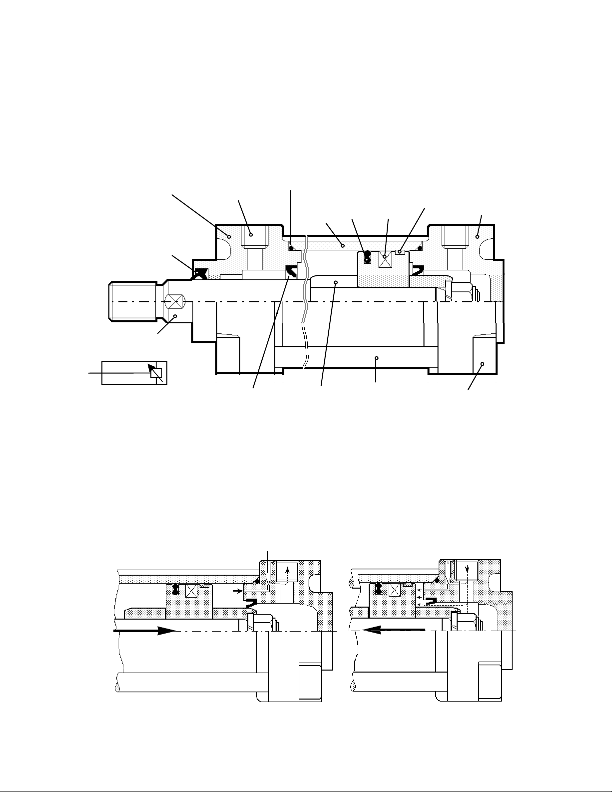
P N E U M A T I C T E C H N O L O G Y
Front or Rod Cover
Port
Barrel Seal
Cylinder
Piston
Seal
Magnetic
Ring
Ring
Back or
Cover
Cushion Seal
Cushion
Barrel
Tie Rod
Tie Rod Nut
Piston Rod
Scraper Ring /
Rod-Seal
ISO Symbol
Cyl ind e r C o nst r uct i on
The construction of a double acting cylinder is shown. The barrel is normally made of seamless tube which
may be hard coated and super-finished on the inner working surface to minimize wear and friction. The end caps
may be aluminum alloy or malleable iron castings held in place by tie-rods, or in the case of smaller cylinders, fit
into the barrel tube by screw thread or crimped on. Aluminum, brass, bronze, stainless steel or synthetic material
may be used for the cylinder body. Stainless steel or composite fiber synthetics are often used in aggressive or
unsafe environments.
Barrel or
Tube
Guiding
or Wear
Head
Rod End
Blind
End
Fig. 6.3 Component parts of a double acting air cylinder with air cushions
Cu s hio n ing
Pneumatic cylinders are capable of very high speed and considerable shock forces can be developed at the
end of the stroke. Smaller cylinders often have fixed cushioning, i.e. rubber bumpers, to absorb the shock and
prevent internal damage to the cylinder. On larger cylinders, the impact effect can be absorbed by an air cushion
that decelerates the piston over the last portion of the stroke. This cushion traps some of the exhausting air near
the end of the stroke before allowing it to bleed off more slowly through an adjustable needle valve (Fig.6.4).
Adjusting Screw
Fig. 6.4 Principle of the Air Cushion
DO NOT COPY WITHOUT WRITTEN PERMISSION – 55 –
Page 62
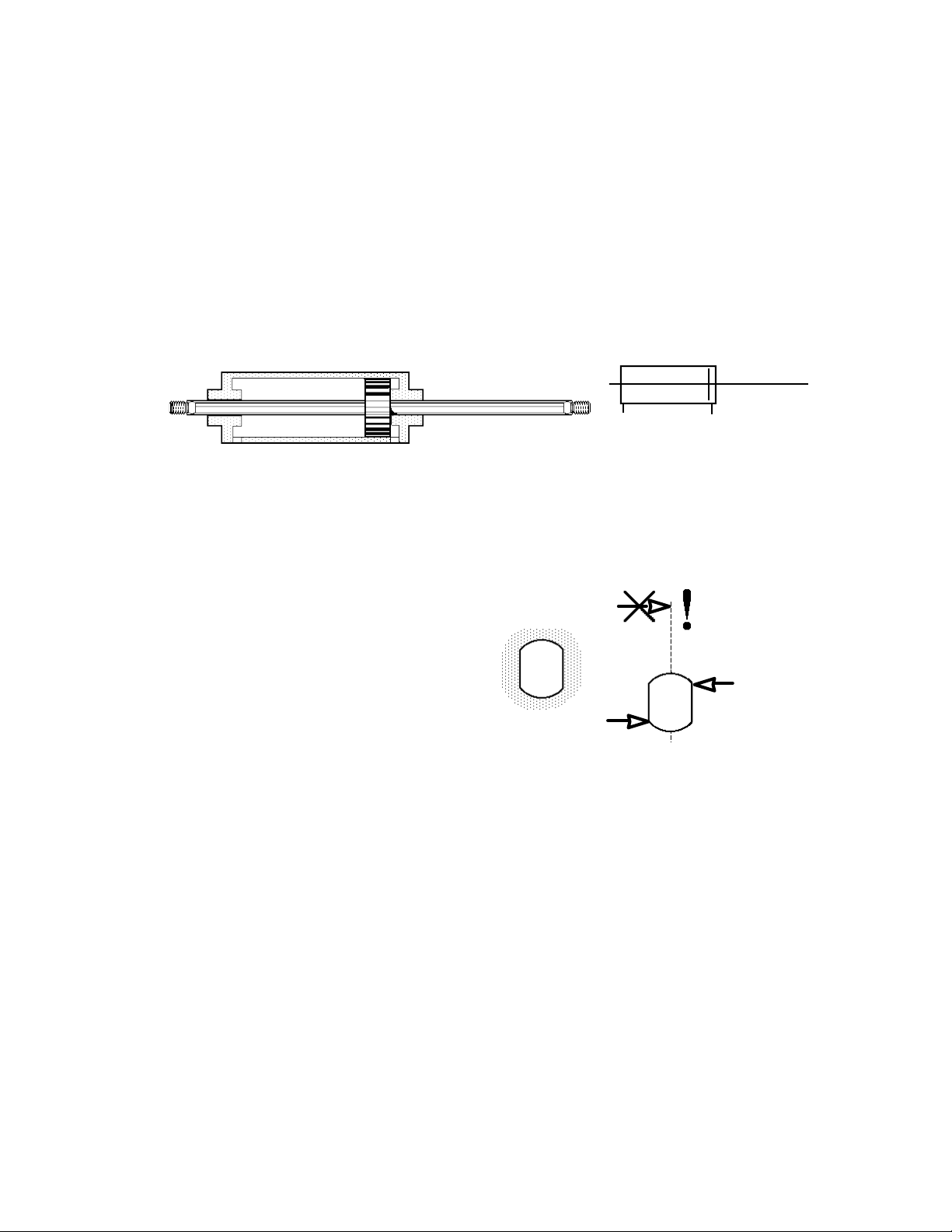
P N E U M A T I C T E C H N O L O G Y
The normal escape of the exhausting air to the outlet port is closed off as the cushion piston enters the cushion
seal, so that the air can only escape through the adjustable restriction port. The trapped air is compressed to a
relatively high pressure, which reduces the inertia of the piston, acting as a brake.
When the piston reverses, the cushion seal acts as a check valve to allow airflow to the piston. It however
restricts the airflow and delays the acceleration of the piston. The cushioning stroke should therefore be as short
as possible.
To decelerate heavy loads or high piston speeds, an external shock absorber is required. If the piston speed
exceeds about 500 mm/s an external mechanical stop must be provided, which is also the case with built-in
cushioning.
S P E C IA L C YL I N D E R O P T IO N S
Do u ble Rod
ISO Symbol
Fig. 6.5 Principle of the double rod
A double rod makes a cylinder stronger against side load, as it has two bearings at the widest distance
possible. This type of cylinder is often mounted with the rods fixed and the cylinder itself moving to displace a part.
No n Ro t ati ng R od
The piston rod of a standard cylinder rotates slightly as there is no guide to prevent this. Therefore it is not
possible to directly mount a tool, e.g. a cutting blade.
For this kind of application, where no
considerable torque is exercised on the tool, a
cylinder with non-rotating rod can be used. The
suppliers specify the maximum allowable torque.
As Fig. 6.6 shows, two flat planes on the rod and
a fitting guide prevent the rotation.
It shows also how a torque creates a high
force on the edges of the rod profile, which will
damage it in the long run.
Tw i n R o d
This type of cylinder has a high lateral load resistance and high non-rotating accuracy. These compact dual rod
cylinders are of high precision and ideal for pick and place operations. Do not assume that the dual cylinders
equal the theoretical force of one larger cylinder’s theoretical force, e.g. two 25 mm. bores in a dual rod cylinder
produce half the force of one 50 mm bore cylinder (prove this).
Fig. 6. 6 Non-Rotating Rod
DO NOT COPY WITHOUT WRITTEN PERMISSION – 56 –
Page 63
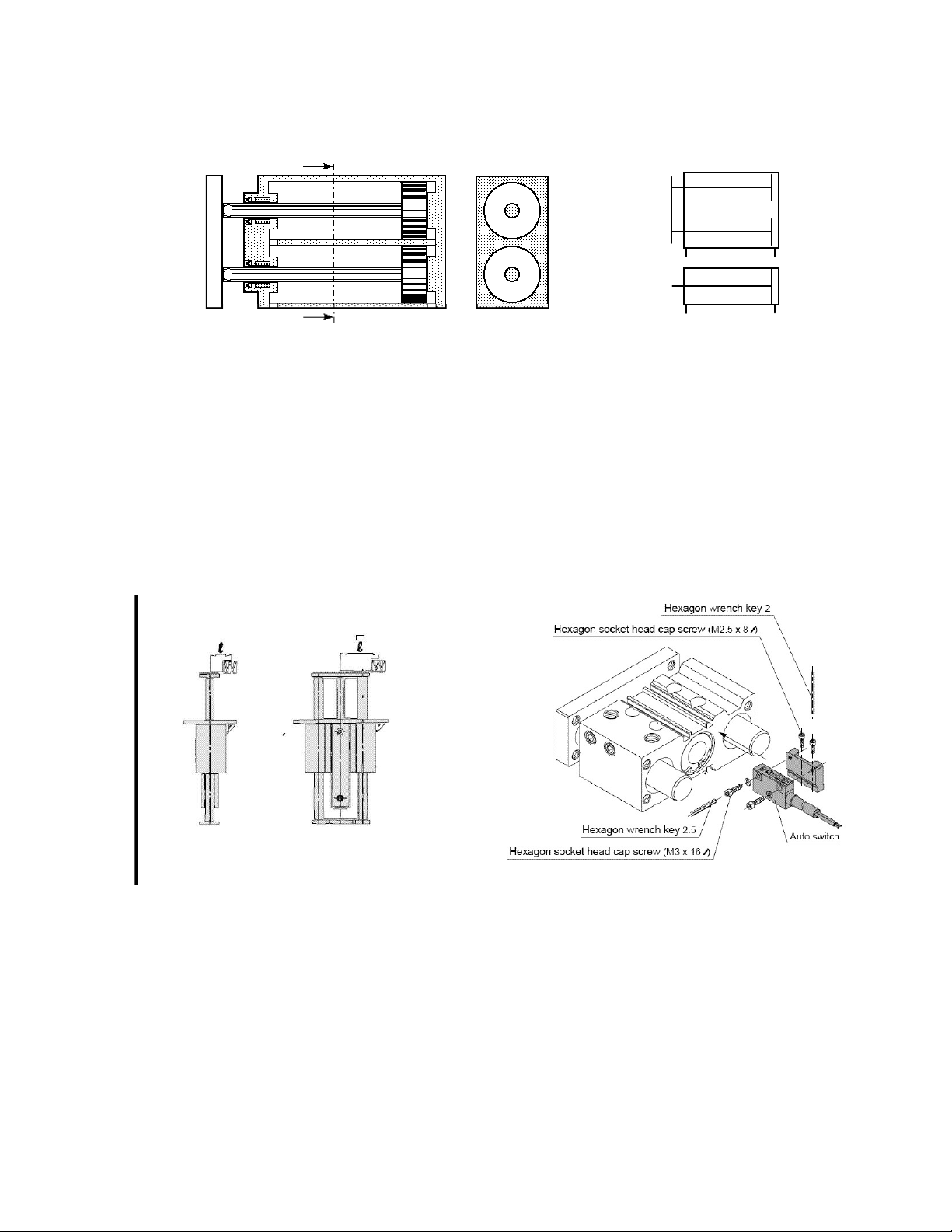
P N E U M A T I C T E C H N O L O G Y
Symbol:
Unofficial:
ISO:AA
Section A-A
Fig. 6.7 Twin Rod Cylinder
Gu i ded Cyl i nd e r
Guided cylinders operate with one cylinder and a guide, also providing lateral load resistance and non-rotating
accuracy. There are two types of guide cylinders:
1. Slide Bearing, which is used to resist lateral movement.
2. Ball Bushing, which is used for pushing and lifting where greater linearity is needed.
Fig. 6.8 Guided Cylinder
DO NOT COPY WITHOUT WRITTEN PERMISSION – 57 –
Fig 6.9 Compact Guided Cylinder
Page 64
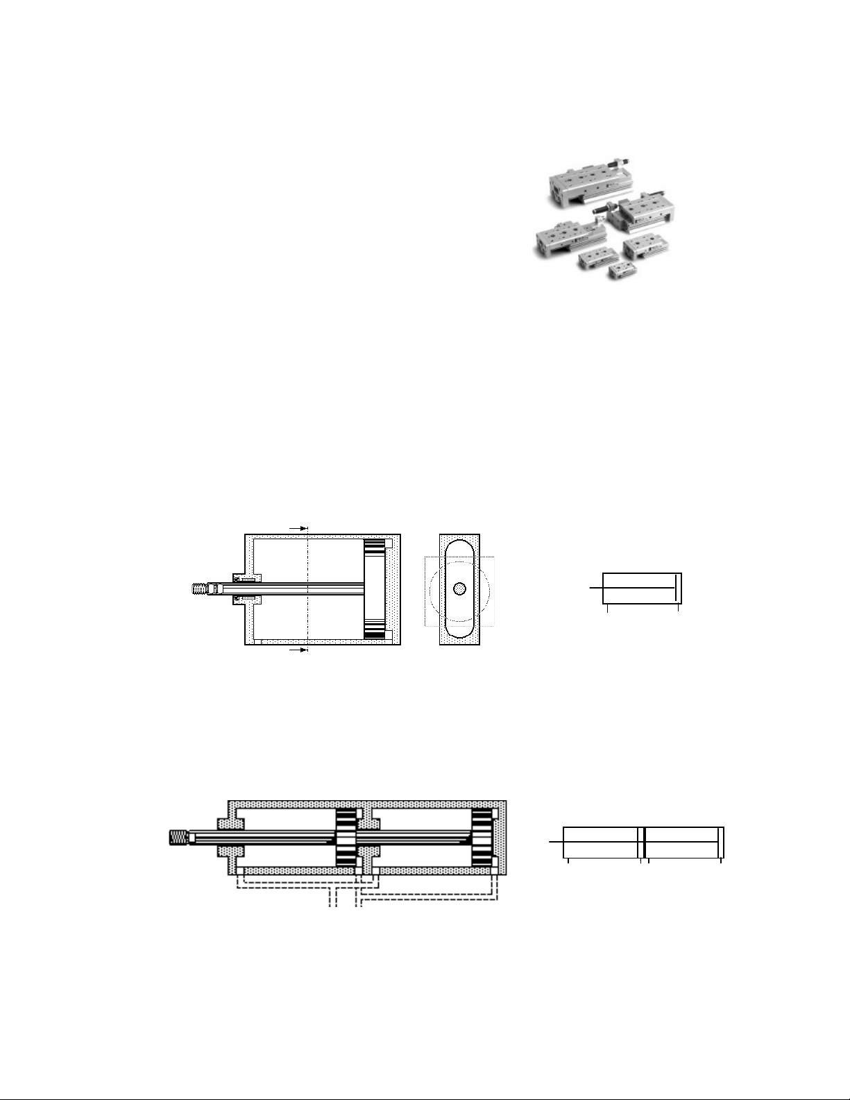
P N E U M A T I C T E C H N O L O G Y
ISO Symbol :
Sli d e T abl e
A precision guided work table and cylinder are
combined to provide even greater linearity, lateral load
resistance, non-rotating accuracy.
Fig 6.10 Examples of Slide Tables
Fl a t C y lin d er
A cylinder normally has square covers and, generally, a round cylinder. By stretching the piston to a relatively
long rectangular shape with round ends, it achieves the same force as a conventional cylinder. The advantage, of
course, is the saving in space achieved if they are to be stacked together. This is suitable for most non-rotating
applications.
A
A
Section A-A
ISO Symbol :
Fig. 6.11 Principle of a Flat Cylinder
Tan dem Cyl i nde r
A tandem cylinder consists of two double acting cylinders joined together with a common piston rod to form a
single unit.
Fig. 6.12 Principle of the Tandem Cylinder
By simultaneously pressurizing both cylinder chambers the output force is almost double that of a standard
cylinder of the same diameter. It offers a higher force from a given diameter of cylinder; therefore it can be used
where installation space restricts the diameter that can be fitted.
DO NOT COPY WITHOUT WRITTEN PERMISSION – 58 –
Page 65
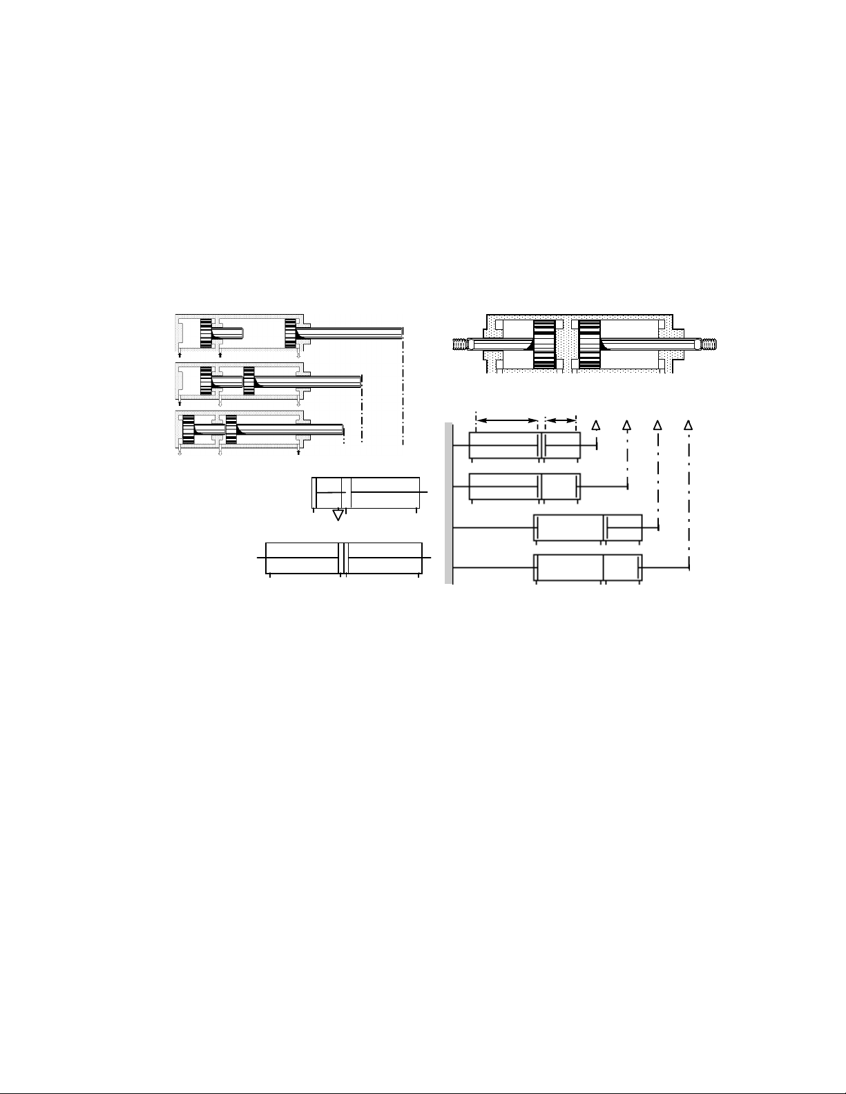
P N E U M A T I C T E C H N O L O G Y
012
0
100
200
300
Stroke Lengths
Positions
ISO Symbols :
Mul t i P o sit i on C yli n de r
The two end positions of a standard cylinder provide two fixed positions. If more than two positions are
required, a combination of two double acting cylinders may be used.
There are two principles:
For three positions, the assembly on the left is required; it enables users to mount the cylinder body to the
machine. It is very suitable for vertical movements, e.g. in handling devices.
The second is to mount two independent cylinders together back to back. This allows four different positions,
but one rod must be attached to the machine, and the cylinder body and other rod must be allowed to move. A
combination with three cylinders of different stroke length gives 8 positions, one with four 16, but a rather exotic
structure is required and the movement, when cylinders run in opposite directions, is very unstable.
200 100
Fig. 6.13 Three and four position cylinder
DO NOT COPY WITHOUT WRITTEN PERMISSION – 59 –
Page 66
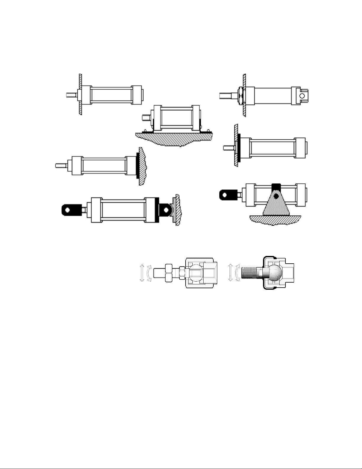
P N E U M A T I C T E C H N O L O G Y
C Y L I N D ER M O U N T I N G
To ensure that cylinders are correctly mounted, manufacturers offer a selection of mountings to meet all
requirements including pivoting movement using swivel type mountings.
Direct
Foot
Rear flange
Rear Clevis
Threaded neck
Front flange
Trunnion (mid)
Fig. 6.14 The various methods of Cylinder Mounting
Fl o ati n g J o in t s-- - Ro d A l ign m ent Co u ple r s
To accommodate unavoidable
"misalignment" between the
cylinder rod movement and the
driven object, a floating joint must
be fitted to the piston rod end.
The investment in these
devices will insure longer cylinder
life and more reliable operation --far exceeding the cost of the
device itself.
Fig 6.15 “Floating joint”
DO NOT COPY WITHOUT WRITTEN PERMISSION – 60 –
Page 67
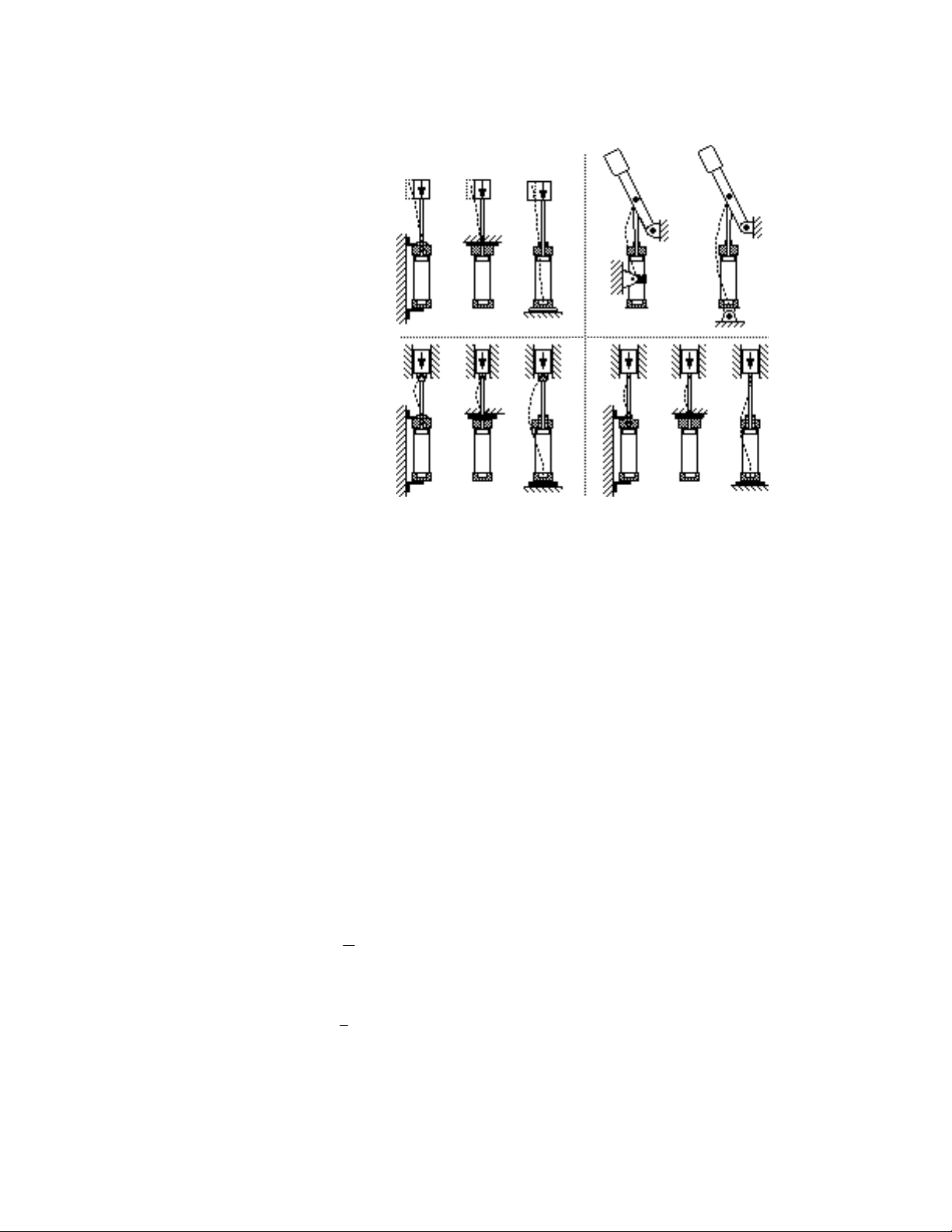
Co l umn Str e ng t h
on one side and
2
3
4
4
P N E U M A T I C T E C H N O L O G Y
When excess thrust is applied to a
cylinder the buckling strength must be
taken into consideration. This excess
thrust can manifest itself when there is
-:
1 -: Compressing Stress.
2 -: If the stressed part, i.e. a
cylinder, is long and slender.
The buckling strength depends
greatly upon the mounting method.
There are four main cases:
1. Rigidly fixed
loose at the opposite end.
2. Pivoting on both ends.
3. Rigidly fixed on one side,
pivoting on the other.
4. Rigidly fixed at both ends.
The above-mentioned conditions apply if a cylinder lifts or pushes a load; it is then subjected to compressing
stress. If a certain specified stroke length is exceeded, the cylinder can “break out’ sideways and seize thus
rendering the cylinder useless. To avoid unnecessary loss of time and money, check with the “buckling length
table” in the supplier’s catalogue. The general rule of thumb is if the stroke of cylinders above 50 mm bore is three
times the diameter or, in the case of smaller cylinders, the stroke is five times the bore and the cylinder is pushing
a load.
Fig. 6.16 The four mounting cases
1
CYLI NDER SI ZING
C Y L I N D ER F O R C E ( T H E OR E T I C A L F O R C E )
Linear cylinders have the following standard diameters as recommended in ISO:
8, 10, 12, 16, 20, 25, 32, 40, 50, 63, 80, 100, 125, 140, 160, 200, 250, 320 mm
The force developed by a cylinder is a function of the piston diameter, the operating air pressure and the
frictional resistance. For the theoretical force, the thrust on a stationary piston, the friction is neglected. This,
theoretical force, is calculated using the formulae Force = Pressure * Area (F = PA):
Force (N) = Piston area (m2) · air pressure (N/m2), or
Force (lbf.) = Piston area (in2) · air pressure (lbf./in2)
Thus for a double acting cylinder:
Extending stroke: FE =
Where (D = piston diameter, pg = Working (gauge) pressure)
Retracting stroke: FR =
4
· D2 · pg
· (D2 - d2) · pg where (d = piston rod diameter)
DO NOT COPY WITHOUT WRITTEN PERMISSION – 61 –
Page 68

P N E U M A T I C T E C H N O L O G Y
4
4
25 30
50 63 80
p
40
4 6 8 10 12 20 16
And for a single acting cylinder:
F
=
E s
It may be quicker to use a diagram such as the one in Fig. 6.17, showing the theoretical force for 1.0, .7 and .5
MPa, or any similar supplier’s information to select a cylinder size.
2.5
1000
ø (mm)
· D2 · pg - Fs (Fs = Spring force at the end of stroke)
100000
500
400
(N)
300
250
F
200
150
125
100
50
30
25
20
15
12.5
10
5
4
2.5
Example: Determine the theoretical size of a cylinder operating at a pressure of 6 bar that would generate a
clamping force of 1600 N.
32 40
Fig. 6.17 Theoretical Force of pneumatic cylinders, from 2.5 to 30 mm (left and top scales)
and from 32 to 300 mm (right and bottom scales) for 1.0, .7 and .5 MPa working pressure
(MPa)
:
1.0 .7 .5
100
125 140 160
ø (mm)
200
250 300
50000
40000
25000
20000
15000
12500
10000
5000
4000
2500
2000
1500
1250
1000
500
400
250
(N)
F
Assuming an extending stroke: - FE =
4 F
Transposing: D =
A 63 mm diameter cylinder would be selected, the larger size providing extra force to overcome frictional
resistance.
By using the diagram, we look for 1600 N on the Force Scale at the right side and find 1500 as a dashed line. We
follow it to the left until we reach a point between the Pressure Lines for .5 and .7 MPa and find an
intersection between 50 and 63 mm on the Diameter Scale on the bottom. There is no doubt that the same
diameter is correct for 1600N as well as 1500 N.
DO NOT COPY WITHOUT WRITTEN PERMISSION – 62 –
p
E
=
D2 * p
4 *1600 N
* 600000 N / m
= 0.0583 m = 58.3 mm.
2
Page 69
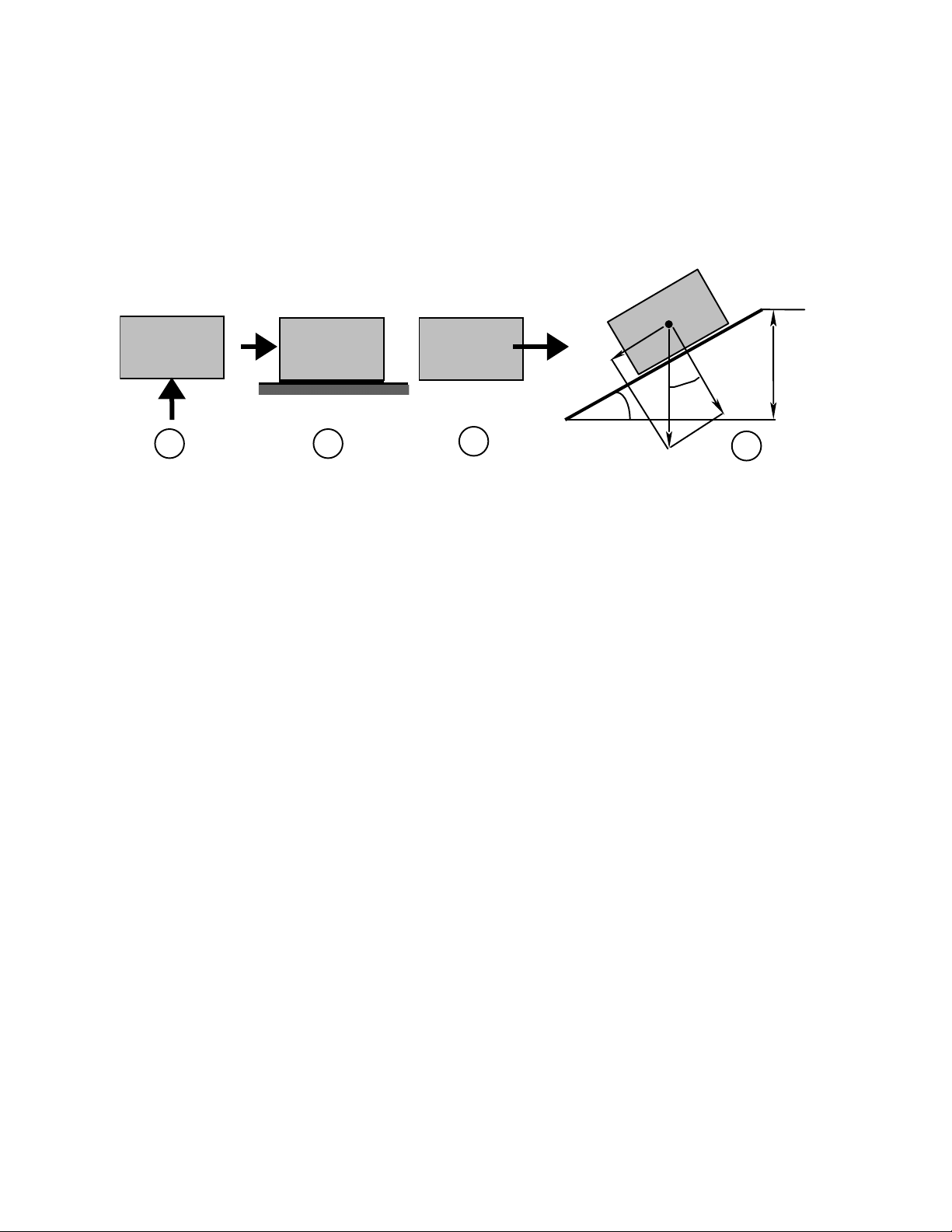
P N E U M A T I C T E C H N O L O G Y
F=G
F
= µ ·
G
W
=m/
2 ·
v
F =G
· (sin
+ µ · cos
)
Req uir e d F o rce
The required force depends on the mass of the load, the angle of movement or elevation, the friction, the
working pressure and the effective piston area.
The load consists of the Weight of the mass (Fig. 6.18 a), the Force R represented by the friction factor times
mass (Fig. 6.18 b) and the required acceleration (Fig. 6.18 c). The re–partition of these forces depends on the
angle of the cylinder axis with the horizontal plane (elevation) as shown in Fig. 6.18 d.
R
a
2
a
x
B
h
y
G
A
a
A horizontal movement (elevation = 0°) has only friction to overcome. Friction is defined by the friction
coefficient µ, which varies between about 0.1 to 0.4 for sliding metal parts, and about 0.005 for iron, rolling on iron
(0.001 for balls on the ring in a ball bearing). This coefficient enters the formula as a cosine, which varies from 1
for horizontal to 0 for vertical.
The mass represents a load, equal to its weight, when the movement is vertical (90° elevation). The weight is
the force created by the earth's acceleration on the mass. The earth's acceleration equals, on a latitude of 450
(Standard for Europe and N. America), 9.80629 m·s-2 or 32.17 ft sec2. With a horizontal movement the weight is a
zero load as it is fully born by the construction. The entire cylinder thrust is then available for acceleration. The
load of the mass varies therefore with the inclination from 0 to 100%. Its value as a factor is the sine of the
inclination angle, 0 for horizontal, and 1 for vertical:
b c
Fig 6.18 The component forces of the LOAD
d
DO NOT COPY WITHOUT WRITTEN PERMISSION – 63 –
Page 70

L O AD R A T I O
P N E U M A T I C T E C H N O L O G Y
This ratio is generally referred to as “Lo” and equals
A cylinder should not have a higher load ratio than about 85%. If an accurate speed control is required or load
forces vary widely, 60-70% should not be exceeded --- perhaps no more than 50% in vertical applications.
Table 6.19 gives the Load Ratio for cylinders from 25 to 100 mm diameter and various elevations and two
friction coefficients for rolling (0.01) and sliding steel parts (0.2).
Bore Mass (kg)
25
50 – – – – – – – .22 4.0
25 – (8.72) (9.67) 7.15 8.49 5.09 6.74 .1 2.0
12.5 5.18 4.36 4.83 3.57 3.45 2.54 3.37 0.05 1.0
32
90 - - - - – 0.22 4.39
45 - (9.56)
22.5 5.49 4.78 5.3 3.92 4.66 2.79 3.7 0.055 1.1
40
50
200 - – – _ – 0.2 4.0
100 – (8.7) (9.65) 7.13 8.48 5.08 6.73 0.1 2.0
50 5.0 4.35 4.83 3.57 4.24 2.54 3.36 0.05 0.0
63
80
100
800 – – – – 0.2 4.0
400 – (8.7) (9.65) 7.14 8.44 5.08 6.73 0.1 2.0
200 5.0 4.35 4.83 3.57 4.22 2.54 3.36 0.05 1.0
100 – – – – – – – .4 8.0
180 - - - - - 0.44 8.78
250 – – – – – – – 0.39 7.8
125 – – – – – (9.92) – 0.2 3.9
65 – – – 7.24 (8.6) 5.16 6.83 0.1 2.03
35 5.46 4.76 5.28 3.9 4.63 2.78 3.68 0.05 1.09
400 -- - - - 0.4 7.99
650 – – – – 0.41 8.18
300 – – – – 0.19 3.78
150 (9.44) 8.23 (9.12) 6.74 8.01 4.8 6.36 0.09 1.89
75 4.72 4.11 4.56 3.37 4.01 2.4 3.18 0.05 0.94
1000 – – – – 0.39 7.81
500 – – – – 0.2 3.9
250 (9.76) 8.5 (9.43) 6.97 8.28 4.96 6.57 0.1 1.95
125 4.88 4.25 4.71 3.48 4.14 2.48 3.28 0.05 0.98
1600 – – – – 0.4 7.99
60° 45° 30°
µ
0.01
Required force
Theoretical Force
µ 0.2 µ
0.01
- 7.84 (9.31) 5.58 7.39 0.11 2.2
· 100%
µ 0.2 µ
0.01
µ 0.2 µ
0.01
µ 0.2
Table 6.19 Load Ratios for 0.5 MPa working pressure and friction coefficients of 0.01 and 0.2
DO NOT COPY WITHOUT WRITTEN PERMISSION – 64 –
Page 71
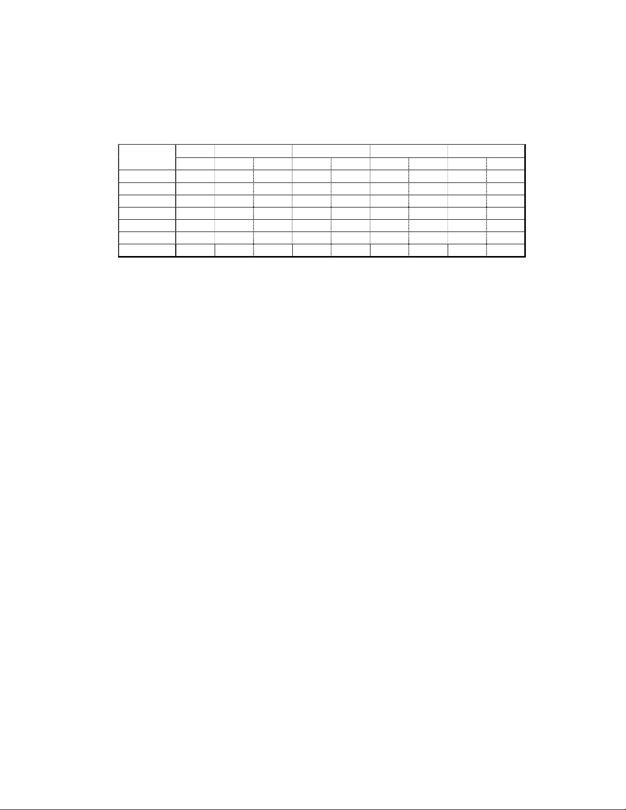
P N E U M A T I C T E C H N O L O G Y
A more practical help for finding the correct cylinder diameter would be to know the allowed load under various
conditions. Therefore, Table 6.20 shows the mass of the total load in kg that results in a Load Ratio of 85%. It is
based on .5 MPa working pressure on the cylinder and again the two friction coefficients 0.01 for rolling (left
column) and 0.2 for sliding (right column). These values are the maximum mass of the total load.
60° 45° 30°
CYL Bore µ: 0.01 0.2 0.01 0.2 0.01 0.2 0.01 0.2
25
32
40
50
63
80
100
2.12 2.45 2.2 3.0 2.5 4.25 3.15 212.3 10.6
3.92 4.5 4.05 5.48 4.62 7.7 5.82 392.0 19.6
5.45 6.25 5.64 7.63 6.42 10.7 8.09 545.0 2.7.5
8.5 9.77 8.8 11.9 10.02 16.73 12.64 850.0 42.5
13.5 15.5 13.98 18.9 15.92 26.55 20.05 1350.0 67.5
21.77 25.0 22.55 30.5 25.67 42.8 32.35 2177.5 108.9
34.02 39.05 39.08 35.2 47.62 66.92 50.55 3402.0 170.1
Table 6.20 Mass in kg for cylinders from 25 to 100 mm Diameter for a Load Ratio of 85% with 0.5 MPa
working pressure.
DO NOT COPY WITHOUT WRITTEN PERMISSION – 65 –
Page 72
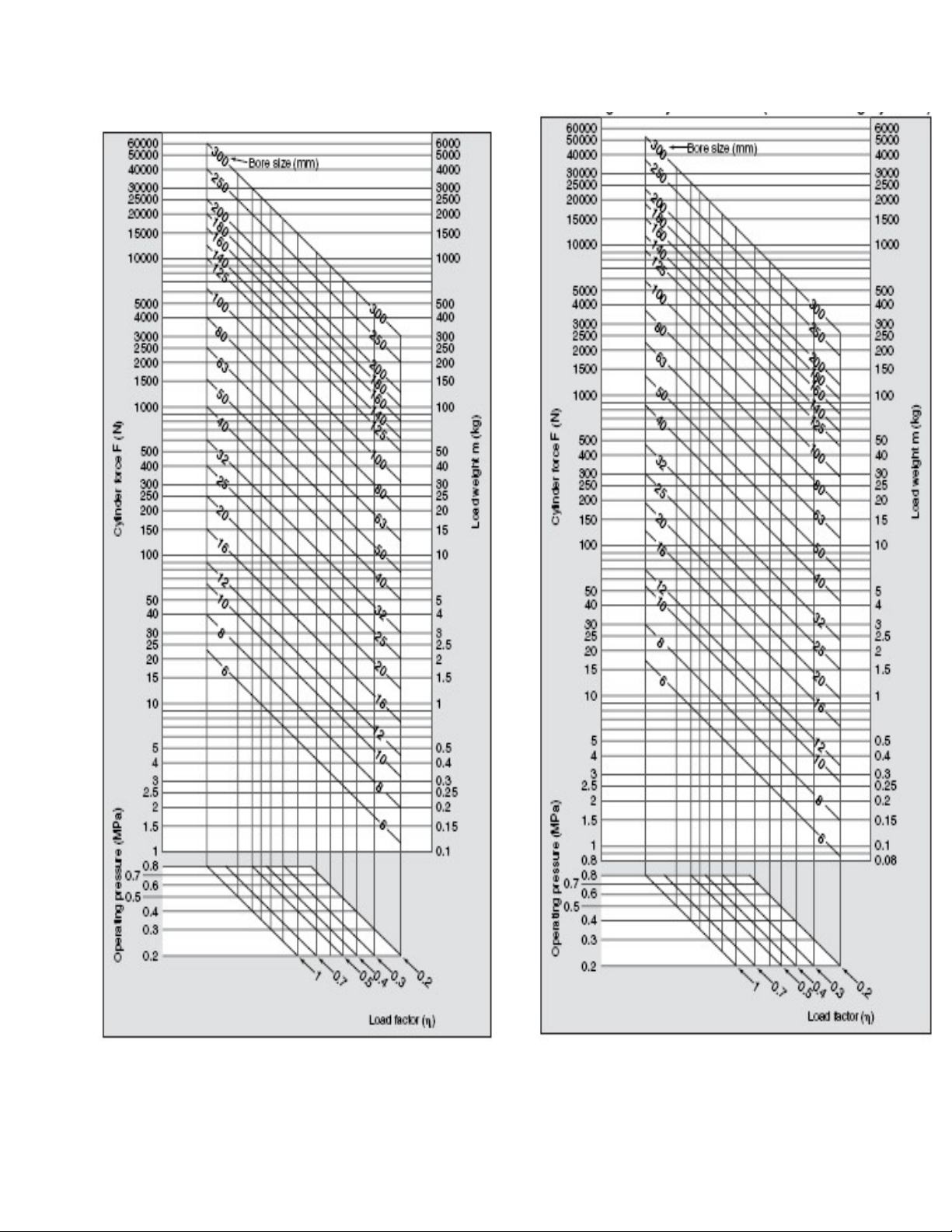
P N E U M A T I C T E C H N O L O G Y
Retracting Side Cylinder Force (Double acting cylinder)
Fig. 6.21 Extending Side Cylinder Force (Double acting
cylinder)
DO NOT COPY WITHOUT WRITTEN PERMISSION – 66 –
Fig. 6.22
Page 73

P N E U M A T I C T E C H N O L O G Y
S P E E D C O N T R O L
The speed of a cylinder is defined by the extra force behind the piston, above the force opposed by the load.
The load ratio should never exceed 85% approx. The lower the load ratio the better the speed control, especially
when the load is subject to variations. A positive speed control is obtained by throttling the exhaust of the cylinder
by means of a “Speed Controller”, which is a combination of a check valve, to allow free flow towards the cylinder,
and an adjustable throttle (needle valve). An example of speed control is shown in the section on valves in the
chapter on Auxiliary Valves. To get a constant speed, the Load Ratio should be approximately 75% or less.
Force is mass (W/g) times acceleration. The units are for force: kg · m · s-2 and for acceleration: m · s-2. In
English units W = lbs and g = 32.17 ft/sec2.
Example: Mass of the load 100 kg, working pressure .5 MPa, Cylinder Diameter 32 mm, horizontal movement
with a friction coefficient of 0.2. The theoretical force is 401.2 N
Table 6.19 shows this case and 90 kg mass a load ratio of 43.9 %.
Thus for 100 kg: 43.9 ·
100
= 48.8 %.
90
The Force of the load is 48.8% of 401.92 N = 196 N. With a cylinder efficiency of 95%, 95 - 48.8% = 46.2%
of the force is left for the acceleration of the load. This is 185.7 N. The acceleration is therefore: 185.7 kg ·
m · s-2 / 100 kg = 1.857 m· s-2. Without control, the piston would theoretically approach 2 m/s after one
second. “Theoretically” means, if there is no limitation to the access of compressed air behind and no
backpressure in front of the piston.
The limitation of the exhaust airflow creates a pneumatic load, which is defined by the piston speed and the
volume flow through the restriction of the speed controller. Any increase of the piston speed increases the
opposing force. This limits and stabilizes the piston speed. The higher the pneumatic part of the total load is, the
stronger it can stabilize the piston speed.
With a load ratio of 85% and a cylinder efficiency of 95%, 10 percent of the force is stabilizing the pneumatic
load. When the mechanical load shows a variation of ± 5% there is a compensation of half the influence. With a
load ratio of for example 50%, these variations will no longer have any visible effect on the speed.
Note: For a subtle speed control, the flow capacity of the tube has to be much higher than that of the speed
controller setting. With a tube that is too small in diameter the tube limits the flow and changing the needle position
has little effect.
AI R F L O W A N D C O N S U M P T I O N
There are two kinds of air consumption for a cylinder or pneumatic system.
The first is the average consumption per hour, a figure used to calculate the energy cost as part of the total
cost price of a product and to estimate the required capacity of compressor and air main.
The second is the peak consumption of a cylinder required to ascertain the correct size of its valve and
connecting tubes, or for a whole system, to properly size the F.R.L. unit and supply tubes.
The Air Consumption of a cylinder is defined as:
Piston area · Stroke length · number of single strokes per minute · absolute pressure in bar,
Explanation: When the piston is against the cylinder cover (Fig. 6.23 a), the volume is zero. When we pull the
rod out until the piston is on the opposite end, the cylinder is filled with atmospheric pressure of 101325
Pa
(Fig. 6.23 b). When the pressure from the supply enters, the swept volume times the gauge pressure
abs
in bar is added, in addition to the atmospheric pressure of 101325 Pa.
DO NOT COPY WITHOUT WRITTEN PERMISSION – 67 –
Page 74
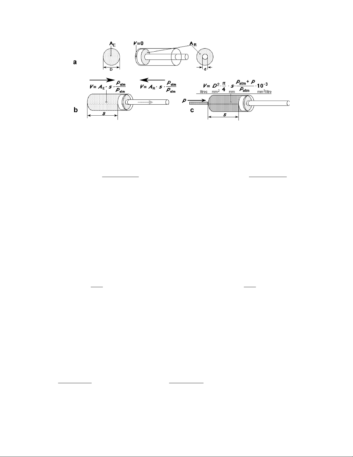
P N E U M A T I C T E C H N O L O G Y
a
1.0
)1.0(P
1.0
)1.0(P
q = Air consumption required for one stroke of air cylinder
1.0
P
1.0
P
qqqqq
qqq
q
q
1
q
q
2
b c
Fig 6.23 Theoretical Air Consumption of a cylinder
The theoretical air consumption of a cylinder is conceptualized as indicated in Fig. 6.23. To further clarify, see
the following formulae:
1. The air consumption of a cylinder equals:
6
LAq
1c1
qc = Air consumption of air cylinder [dm3(ANR)]*
qp = Air consumption of tubing or piping [dm3(ANR)]
[dm3(ANR)]
A = Piston area at extension side [mm2]*
L = Cylinder stroke [mm]
2. The consumption of each tube between valve and cylinder equals:
aq
3. The total consumption equals:
Double Acting Cylinder Single Acting Type Cylinder
11p1
1
1
10
p2c2p1c1
6
10
P = operating pressure [MPa]*
ℓ = Piping length [mm]
a = Piping internal sectional area [mm2]
*Subscript 1: Extension side
*Subscript 2: Retraction side
aq
LAq
2c2
22p2
p1c1
6
2
6
2
10
10
4. Required flow [L/min(ANR)] equals:
p1c1
Q
1
60
t
Q = Required flow [dm3/min (ANR)]
DO NOT COPY WITHOUT WRITTEN PERMISSION – 68 –
Q
p2c2
60
2
t
Page 75

P N E U M A T I C T E C H N O L O G Y
T = time for whole stroke
Subscript 1: Extension side
Subscript 2: Retraction side
Components should be sized to the larger of the two required flows calculated above.
For more precise calculation of air consumption and required air in accordance with specific conditions, please
make use of SMC’s “Model Selection Program” and “Energy Saving Program” @ smcusa.com
Table 6.24 gives the theoretical air consumption per 100 mm of stroke, for various cylinder diameters and
working pressures:
Working Pressure in MPa
Piston dia. 3 4 5 6 7
20
25
32
40
50
63
80
100
0.0124 0.0155 0.0186 0.0217 0.0248
0.0194 0.0243 0.0291 0.0340 0.0388
0.0319 0.0398 0.0477 0.0557 0.0636
0.0498 0.0622 0.0746 0.0870 0.0993
0.0777 0.0971 0.1165 0.1359 0.1553
0.1235 0.1542 0.1850 0.2158 0.2465
0.1993 0.2487 0.2983 0.3479 0.3975
0.3111 0.3886 0.4661 0.5436 0.6211
Table 6.24 Theoretical Air Consumption of double acting cylinders from 20 to 100 mm diameter,
in liters ANR per 100 mm stroke
Example 1. Find the energy cost per hour of a double acting cylinder with an 80 mm diameter and a 400 mm.
stroke with 12 double strokes per minute and a working pressure of .6 MPa
In Table 6.24 we see that an 80 mm diameter cylinder consumes 3.5 liters (approx.) per 100 mm stroke
so:
Q /100 mm stroke x 400 mm stroke x number of strokes per min x forward and return stroke = 3.5 x 4
x 24 = 336 l/min ANR.
In the paragraph "Thermal and Overall Efficiency" in section #4, we find an electrical consumption of 1
kW for 0.12 - 0.15 m3/min with a working pressure of 7 bar. Therefore, to produce 1 m
3
/ min we require
n
approximately 8 Kw of electric power.
We are making the assumption that one kW-hr (kilowatt-hour) costs 5 cents.
The cost of producing a volume flow of 1 m
1 m
3
/min
n
3
n
· 40 cents / hr = 13.4 cents per hour.
/min
In our example:
0.336 m
3
/min is then:
n
5 ct · 8 kW
kW hr
= 40 cents / hr.
The sum of all the cylinders on a machine, calculated that way, represents the air consumption as energy
cost.
It should however be noted that:
• the consumption figures in the above table do not include the “dead volume” at either end of the
stroke, if any, or the air required to fill the connecting tubes for each stroke (see previous page)
• the transfer of energy is not without losses (see further below).
Peak Air Consumption of Actuators
DO NOT COPY WITHOUT WRITTEN PERMISSION – 69 –
Page 76
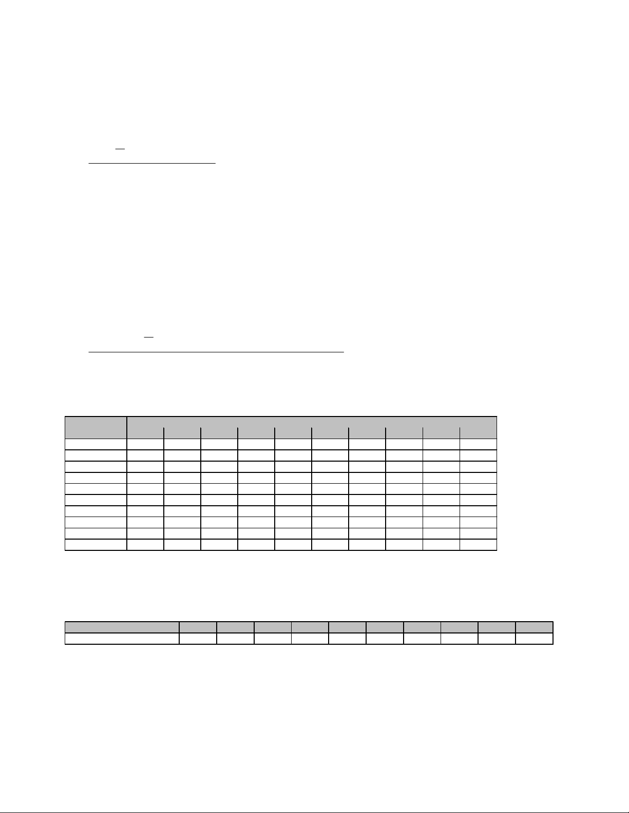
P N E U M A T I C T E C H N O L O G Y
The peak air consumption of an actuator is defined as follows:
Piston area x Piston speed x Absolute pressure
Q
2
4
pvD
60)1.0(
000,100
Q = Peak flow [Nl/min]
D = Piston diameter [mm]
v = Piston speed [mm/s]
p = Pressure [MPa]
Example:
An actuator has a 63 mm bore, an average piston speed of 500 mm/s, and a supply pressure of 0.6 MPa.
What is the peak consumption under these conditions?
2
)63(
Q
4
MPaMPasmmmm
60)1.06.0(/500
min/654
Nl
000,100
The table 6.23 indicates the peak consumption of actuators at different speeds, at a supply pressure of 0.5MPa. If
supply pressure differs from 0.5MPa; use the correction factor in table 6.26.
Average Piston Speed [mm/s]
Bore size 100 200 300 400 500 600 700 800 900 1000
12
16
20
25
32
40
50
63
80
100
Table 6.25 : Peak air consumption of double acting actuators in Nl/min with 0.5MPa supply pressure
If system pressure is higher or lower than 0.5MPa, use the correction factor below and multiply with peak
consumption value from the chart above.
Working Pressure [Mp a]
Correction Factor
4 8 12 16 20 24 28 33 37 41
7 14 22 29 36 43 51 58 65 72
11 23 34 45 57 68 79 90 102 113
18 35 53 71 88 106 124 141 159 177
29 58 87 116 145 174 203 232 260 289
45 90 136 181 226 271 317 362 407 452
71 141 212 283 353 424 495 565 636 707
112 224 336 449 561 673 785 897 1009 1122
181 362 543 723 904 1085 1266 1447 1628 1809
283 565 848 1130 1413 1696 1978 2261 2543 2826
0.1 0.2 0.3 0.4 0.5 0.6 0.7 0.8 0.9 1
0.33 0.5 0.67 0.83 1 1.17 1.33 1.5 1.67 1.83
Table 6.26 : Correction factor
DO NOT COPY WITHOUT WRITTEN PERMISSION – 70 –
Page 77
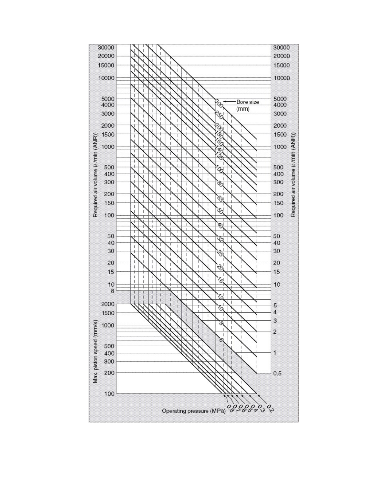
P N E U M A T I C T E C H N O L O G Y
.
Cylinders Air Consumption (For one Cycle)
DO NOT COPY WITHOUT WRITTEN PERMISSION – 71 –
Page 78
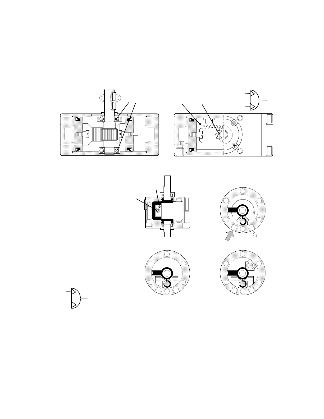
P N E U M A T I C T E C H N O L O G Y
Rack
Pinion
Ball Bearings
ISO Symbol:
ISO Symbol:
Vane
Elastomer
Damper
270°
180°
90°
ROTAR Y ACTU AT ORS
R AC K A N D P I N I O N T Y P E
The output shaft has an integral pinion gear driven by a rack attached to a double piston. Standard angles of
rotation are 90° or 180°.
Fig 6.27Rack and Pinion Rotary Actuator
V AN E T Y P E R O T AR Y A C T U A T O R S :
Air pressure acts on a
vane, which is attached to the
output shaft. A fitted rubber
seal or elastomer coating
seals the vane against
leakage.
A special threedimensional seal seals the
stopper against the shaft and
the housing. The size of the
stopper defines the rotation
angle of 90, 180 or 270°.
Adjustable stops may be
provided to adjust any angle of
rotation of the unit.
Fig 6.28 Vane Type Rotary Actuator
S I Z I N G R O T A R Y A C T U AT OR S
To r que and Ine rti a
Linear cylinders have a cushion to reduce the impact when the piston hits the cover. The capacity of the
cushioning is the kinetic energy it can absorb. This energy equals
propelled with little friction and high speed.
DO NOT COPY WITHOUT WRITTEN PERMISSION – 72 –
m
· v 2. It is most important when a load is
2
Page 79
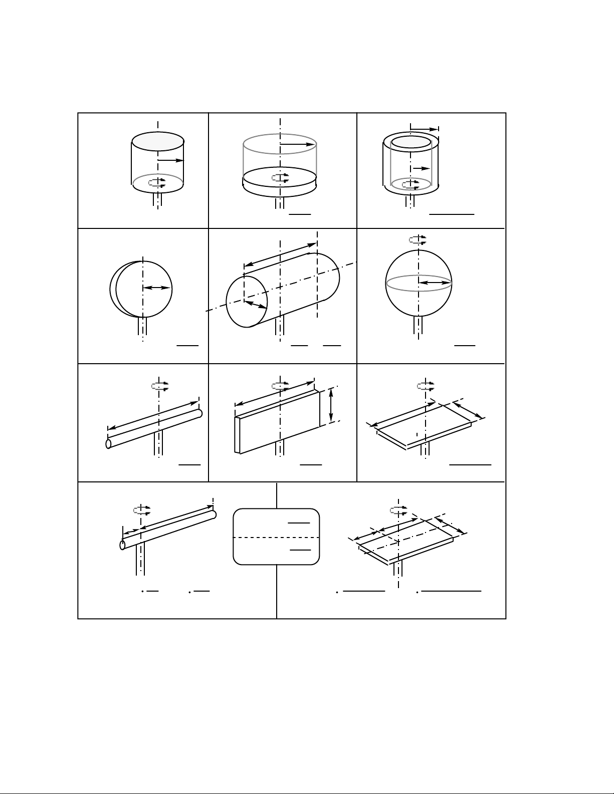
P N E U M A T I C T E C H N O L O G Y
These dynamics are even more important to understand in the case of a rotary actuator. Stopping a rotating
mass without cushioning risks breaking the pinion or vane. The allowable energy published by the manufacturer
must be carefully respected.
r 1
r
J = m·r
r
2
2
J = m ·
a
r
2
J = m ·
ca b
r2
r1 + r2
2
2
2
r
r
2
J = m ·
d e
a
g h i
J = m ·
a
r
4
2
a
12
b
J = m ·
a
J = m ·
m·ma=
m
=bm·
b
a
(
12
a+b
a+b
2
2
r
+
2
a
)
4
b
12
a
a
b
f
a
J = m ·
J = m ·
r
2
2 r
5
b
2
2
a + b
12
2
2
a
+
J = m
k l
a
m
3
2
b
b
3
J = m
a
2
4a + c
12
2
4b + c
m+
b
2
12
Fig. 6.29 Formulae for the moment of inertia of various body shapes
To define this energy we need to know the inertia of the rotating mass. Think of its material being composed of
extremely small parts; the sum of the mass of each individual part, multiplied by the square of its distance from the
rotation axis gives the total inertia.
The basic case is a cylinder. Its inertia equals its mass times the square of the radius:
J = m · r2. (kg · m2)
DO NOT COPY WITHOUT WRITTEN PERMISSION – 73 –
Page 80
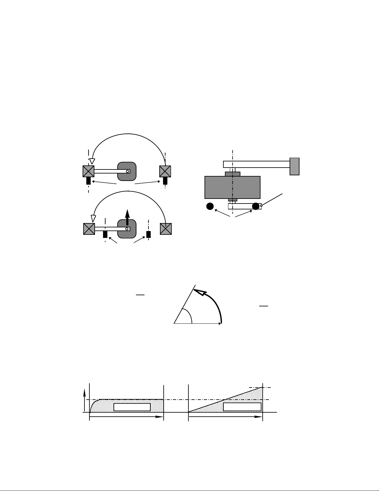
P N E U M A T I C T E C H N O L O G Y
Shock Absorbers
Stopper Lever on
square Shaft End
Reaction
Stops
Stops
=
srrad
r
s1 rad:
57.3°
=
The inertia of more complicated forms has to be calculated with the help of formula for specific shapes. Fig.
6.29 shows the formulae for a number of basic shapes.
A rotating construction has to be split up into basic elements and the partial inertia totaled. For example a
chuck on an arm as in Fig. 6.29k is added to the inertia of the arm by multiplying its mass with the square of the
distance of its center of gravity from the rotation axis.
Whenever possible, rotating masses have to be stopped against a mechanical stop, preferably a shock
absorber. The shock absorber should be placed as far from the axis as possible as in Fig. 6.30a. Any closer to the
center would create a reaction force; see Fig. 6.30b. If an external stop on the arm itself is not possible, it can be
done with a stopper lever on the opposite end of the shaft. This method subjects the actuator to high reaction
forces and should be done only with the consent of the supplier.
a
c
b
Fig. 6.30 Stopping a rotating arm
The inertia for rotating objects is what the moving mass is to a linear movement. The energy is defined by its
speed. For a rotation, the speed is defined by the “Angular Speed ”. It is expressed in radians per second. Fig.
6.31 illustrates these expressions.
t
Fig. 6.31 Definitions of angular speed
As for the cushioning capacity for linear movements, for the maximum allowed energy to be stopped by a rotary
actuator we have to consider the final speed. Acceleration by compressed air, if not limited by a stabilizing
backpressure, may be considered to be almost constant. The movement starts at zero and reaches about double
the average speed (Stroke per time) at the end of stroke.
For fast pneumatic movements, calculations have to be based on twice the average speed as Fig. 6.32
Low Speed High Speed
a b
t
t
Fig. 6.32 Average and final speed
t
t
Final Speed
Average Speed
DO NOT COPY WITHOUT WRITTEN PERMISSION – 74 –
Page 81
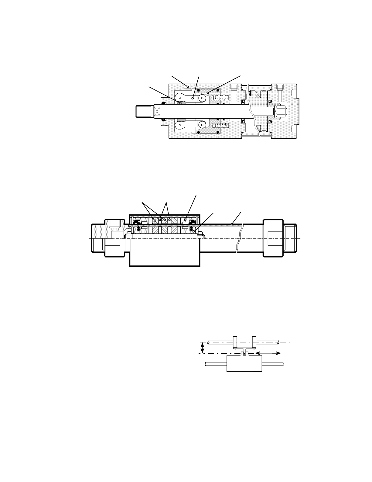
P N E U M A T I C T E C H N O L O G Y
Pilot Port
Clamping Lever
Brake Piston
Shoe
Brake
Magnetic Rings with
opposite polarity
Iron Discs
StainlessSteel
Cylinder Tube
Piston
Carriage
F
X
o
Load
SPE CIAL ACT UATOR S
L O C K I N G C Y L I N D E R
A cylinder can be fitted
with a locking head in place of
the standard end cover.
It will hold the piston rod in
any position. The locking
action is mechanical, so
ensuring the piston rod is
securely held, in the case of
pressure breakdown or even if
pressurized.
R O D L E SS C Y L I N D E RS
Wit h m a gne t ic c oup lin g , u n gu i ded
Fig. 6.33 Typical Locking Cylinder
Fig 6.34. Typical Rodless Cylinder with magnetic coupling between piston and carriage
A conventional cylinder of say 500-mm of stroke may have an overall extended dimension of 1100 mm. A
rodless cylinder of the same stroke can be installed in a much shorter space of approximately 600 mm. It has
particular advantages when very long strokes are required.
The magnetic retaining force limits the force available from a magnetically coupled type of rodless cylinder. It
equals that of a normal rod cylinder, up to .7 MPa working pressure, but with dynamic shocks a separation of the
carriage from the piston is possible. Vertical movements are therefore not recommended, unless a safety margin
specified by the supplier is observed.
When the coupling between the carriage and
the load cannot be done in the centerline of the
cylinder, but at a certain distance (X in Fig. 6.35),
the allowable force decreases drastically. The
data specified by the supplier has to be
respected to avoid damage to the cylinder.
Fig 6.35 Side Load X reduces the allowable load
DO NOT COPY WITHOUT WRITTEN PERMISSION – 75 –
Page 82
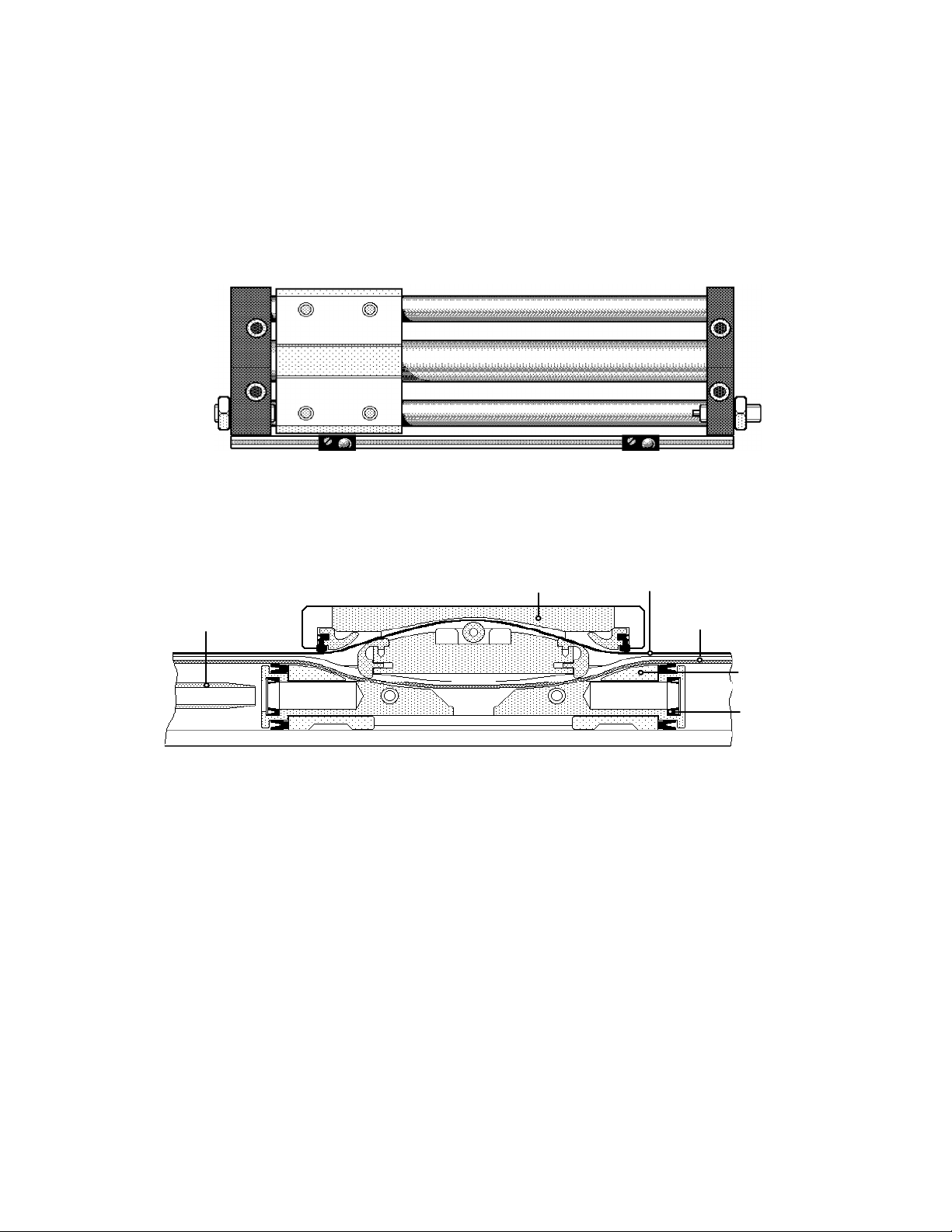
P N E U M A T I C T E C H N O L O G Y
Carrier
Piston
Cushioning Tube
Cushioning
Seal
Covering Strip
Seal Belt
Gu i ded typ es, wit h ma g net ic c oup l ing
Depending on the kind of guide used, the problem of side load can be solved or made worse. With ball
bearings for the guide, a side load can be considerable and also the stroke length. Precision guides however have
so little tolerance that the slightest deformation increases friction. For these types, the stroke length is a main
factor for the allowable force. Suppliers give data for any possible mounting orientation and side load.
Fig. 6.36 shows a typical guided rodless cylinder with magnetic coupling between piston and carriage.
Fig. 6.36 Rodless cylinder with guides, Shock Absorbers and cylinder switches
It is recommended that the carriage is decelerated softly with shock absorbers on both ends; in Fig. 6.36 they
are built in. A rail holds adjustable switches, operated by a magnet built-in to the carriage.
Gu i ded , wi th m ech a nic a l c o upl ing
Fig.6.37 Rodless Cylinder with mechanical coupling
For lifting or moving heavier loads, a "slotted cylinder" type excludes the risk of disconnection of the carrier
from the piston under dynamic shocks, but it is not totally leak free unlike the magnetically coupled type.
DO NOT COPY WITHOUT WRITTEN PERMISSION – 76 –
Page 83
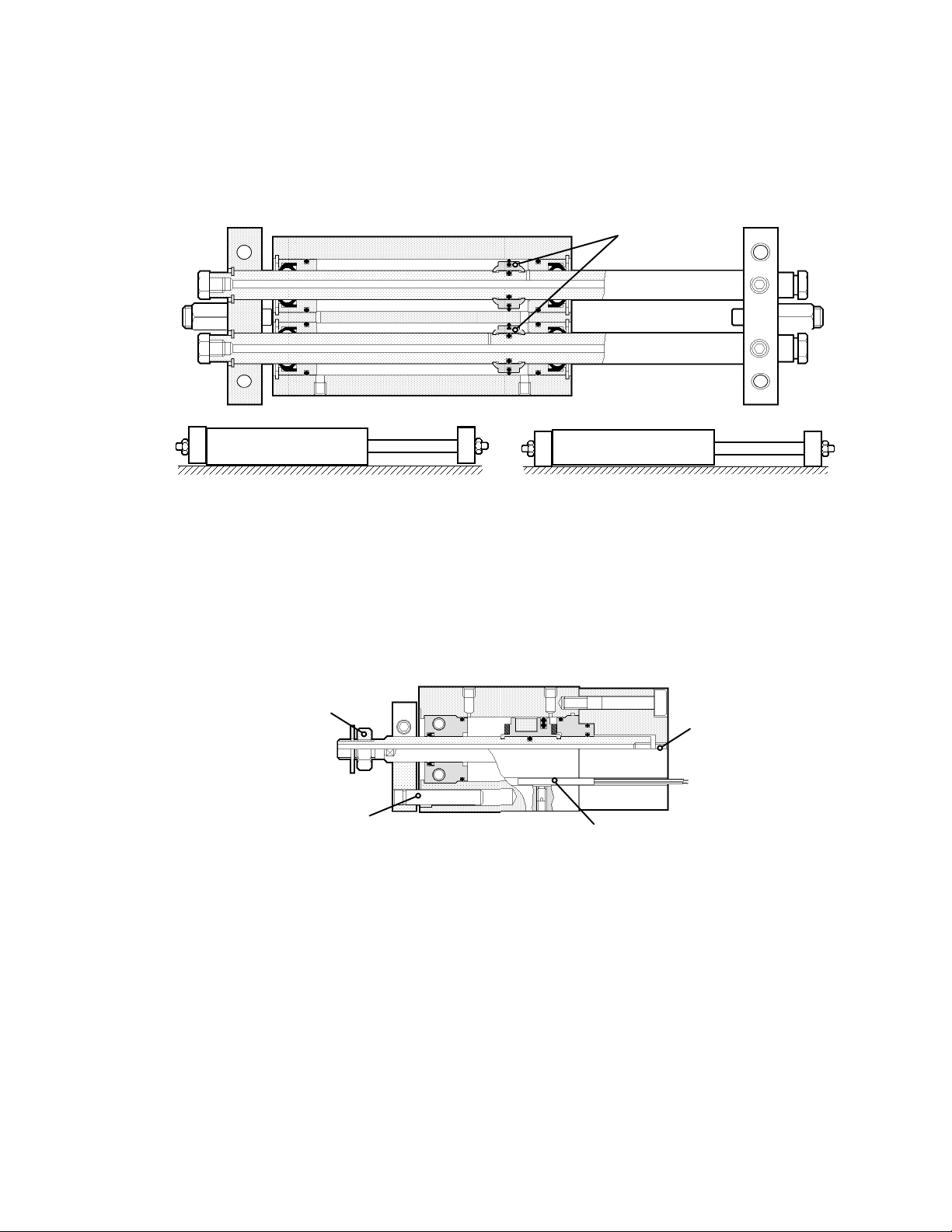
P N E U M A T I C T E C H N O L O G Y
A1
B1AB
Pistons
Vacuum
Connection
(stationary)
Anti-Rotation Rod
Locking Nut for
Vacuum Pad
Switch
Sli d e U nit s
The slide unit is a precision linear actuator of compact dimensions, which can be used on robotic
manufacturing and assembly machines.
a
b c
Fig. 6.38 Typical Slide Unit
Precisely machined work mounting surfaces and parallel piston guide rods ensure accurate straight-line
movement when built in as part of the construction of a transfer and position machine.
In one position, the body can be fixed and the rods with end bars can move (b). Upside down, the end bars
touch the mounting surface and the body can move (c). In both cases, the valve can be connected to the fixed
part, either by the ports A and B, or A1 and B1 in Fig. 6.38 a.
H O L L O W R OD C Y L I N D E R
This actuator is specifically designed for "pick and place" applications.
The hollow rod
provides a direct connection between a
vacuum source and a
vacuum pad, attached
to the rods working
end. The connecting
tube at the rear of the
cylinder remains static,
while the rod extends
and retracts.
Fig. 6.39 Hollow Rod Cylinder with a non moving vacuum connection
DO NOT COPY WITHOUT WRITTEN PERMISSION – 77 –
Page 84
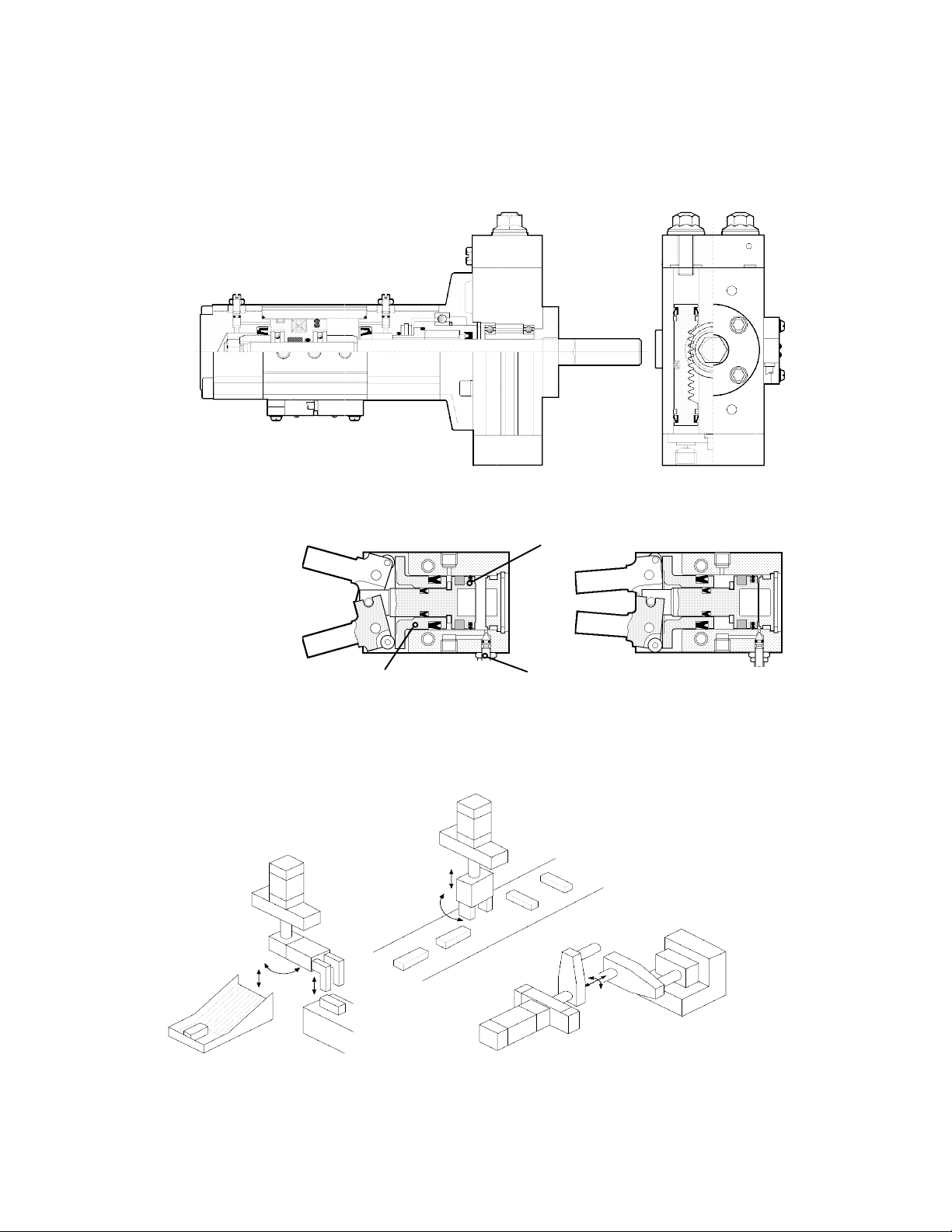
P N E U M A T I C T E C H N O L O G Y
Opened
Closed
Main Piston
Secondary Piston
Speed Control Screw
L I N E A R R O T A T IN G C Y L I N D E R
A so-called rotating cylinder is an assembly of a linear cylinder with a rotary actuator. A rotating arm can be
attached to the shaft and be equipped with a gripper or vacuum pad to pick up work pieces and deposit them in
another location after rotating the arm. This gives a complete “pick and place” unit for materials handling.
Fig. 6.40 Typical Rotating Cylinder
AI R C H U C K ( G R I PP E R )
An actuator designed to
grip components in robotic
type applications.
The type shown has two
opposing pistons, to open
and close the jaws.
Fig.6.41 Typical Pneumatic Fulcrum Type Gripper
Fig.6.42 shows three typical applications of the last two elements:
Fig. 6.42 Typical
Applications of the
Rotating Cylinder
and Air Gripper
DO NOT COPY WITHOUT WRITTEN PERMISSION – 78 –
Page 85
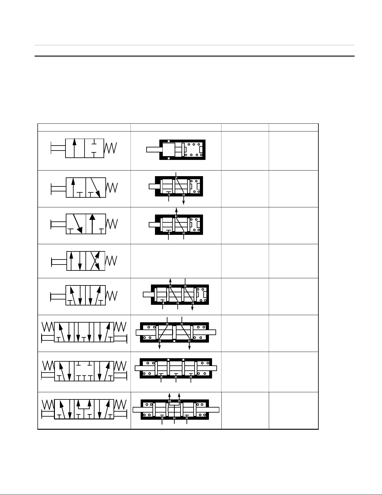
P N E U M A T I C T E C H N O L O G Y
P
B A P EB EA
P
A P EB EA
EB EA
4
3
A P R1 R2
R2
77 DDIIRREECCTTIIOONNAALL CCOONNTTRROOLL VVAALLVVEESS
VALVE FUNCTI ONS
A directional control valve determines the flow of air between its ports by opening, closing or changing its
internal connections. The valves are described in terms of: the number of ports, the number of switching positions,
its normal (not operated) position and the method of operation. The first two points are normally expressed in the
terms 5/2, 3/2, 2/2 etc. The first figure relates to the number of ports (excluding pilot ports) and the second to the
number of positions.
The main functions and their ISO symbols are:
Symbol Principal Construction Function Application
A
P
A
R
P
A
A B
P R
R
4/2 Switching
B
2
1 3
5
B
EA
5
A
A
P
A
A
R P
A B
A B
P
4 2
1
B
P R1
R
EB
Table 7.1 Valve Symbols, Principles, description and main applications
2/2 ON/OFF
without exhaust.
3/2 Normally
closed (NC),
pressurizing or
exhausting the
output A
3/2 Normally
open (NO),
pressurizing or
exhausting the
output A
between output A
and B, with
common exhaust
5/2: Switching
between output A
and B, with
separate
exhausts.
5/3, Open center:
As 5/2 but with
outputs open to
exhaust in midposition
5/3 Closed
center: As 5/2
but with midposition fully
shut off
5/3 Pressurized
center:
Air motors and
pneumatic tools
Single acting
cylinders (push
type), pneumatic
signals
Single acting
cylinders (pull
type), inverse
pneumatic signals
Double acting
cylinders
Double acting
cylinders
Double acting
cylinders, with the
possibility to depressurize the
cylinder
Double acting
cylinders, with
stopping
possibility
Special applications, i.e.
Locking or
Rodless Cylinder
DO NOT COPY WITHOUT WRITTEN PERMISSION – 79 –
Page 86
P N E U M A T I C T E C H N O L O G Y
P O R T I D E NT I F I C A T IO N
The denominations the nomenclature used to identify of the various ports was not uniform until the 5/2 and 5/3.
Until the 5/2 and 5/3 were invented, there was more tradition than any respected standard.
Originally, the codes previously used for older hydraulic equipment were adopted. “P” for the supply port comes
from “pump”, the hydraulic source of fluid energy, and is understood to mean “pressure” in pneumatic systems.
The outlet of a 2/2 (two ports, two positions) or 3/2 valve has always been "A”, with the second, antivalent
output port labeled “B”.
The exhaust port was originally labeled “R” from Return (to the oil tank). We can think of R as return to
atmosphere in pneumatic systems. The second exhaust port in 5/2 valves was sometimes named S, or the former
“R1” and the latter “R2”.
The pilot port initiating the power connection to port A has originally been coded “Z” (the two extreme letters in
the alphabet belongs together) and the other “Y”.
After 20 years of bargaining about pneumatic and hydraulic symbols, one of the ISO work groups had the idea
that ports should have numbers instead of letters, delaying the termination of the standard ISO 1219 by another 6
years. Supply should be “1”, the outputs “2“ and “4”, the pilot port connecting”1” with “2” is then “12” etc. Table 7.2
shows the four main sets of port identifications in use. Preferred are now the ISO numbers.
Standard Supply
Port
NC
output
NO output Exhaust of
NC
Exhaust of NO Pilot for NC Pilot for
Old JIS P A B R S Z Y
ISO 1219 P A B R S Z Y
JIS P A B R1 R2 Z Y
JIS 1 4 2 5 3 14 12
NFPA P A B EA EB PA PB
ISO 5599 1 4 2 5 3 14 12
SMC P (1) A (4) B (2) EA (5) EB (3) PA (14) PB (12)
Table 7.2 Typical port identifications
M O N O S T A B LE A N D B I - S T A B LE
Spring returned valves are monostable (stable in one default or preferred condition). They have a defined
preferred position to which they automatically return. A bi-stable valve has no preferred position and remains in
either position until one of its two impulse signals are operated.
VALVE TYP ES
The two principal methods of construction are Poppet and Slide with either elastic (rubber) or metal seals.
Fig 7.3 relates to the various combinations.
Directional
Control
Valves
Poppet Valves
Spool
Valves
Sliding Valves
Rotary
Valves
Plane Slide
Valves
Fig. 7.3 The various types of valves and sealing methods
Elastomer
Seal
Metal Seal
NO
DO NOT COPY WITHOUT WRITTEN PERMISSION – 80 –
Page 87
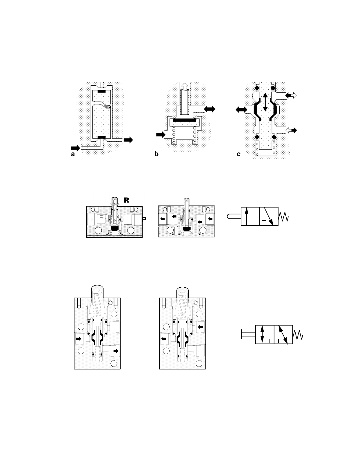
P N E U M A T I C T E C H N O L O G Y
a
A P
P
R
P O P P ET V A L VE S
Flow through a poppet valve is controlled by a disc or plug lifting at right angles to a seat, with an elastic seal.
Poppet valves can be two or three port valves, for a four or five port valve two or more poppet valves have to
be integrated into one valve.
a b c
Fig. 7.4 The main types of poppets
In a) the inlet pressure tends to lift the seal off its seat requiring a sufficient force (spring) to keep the valve
closed. In b) the inlet pressure assists the return spring holding the valve closed, but the operating force varies
therefore with different pressures. These factors limit these designs to valves with 1/8" ports or smaller.
A
A
b
Fig.7.5 Mechanically operated poppet valve
Fig 7.5 a) shows a NC 3/2-poppet valve as shown in Fig. 7.4 b.
In its non-operated position (aa), the outlet exhausts through the plunger. When operated, (bb) the exhaust port
closes and the airflow’s from the supply port P to the outlet A.
Design 7.6 c) is a balanced poppet valve. The inlet pressure acts on equal opposing piston areas.
N.C.
A
N.O.
A
N.C.
N.O.
a b
Fig 7.6 Balanced 3/2 Poppet Valve
This feature allows valves to be connected up normally closed (NC) or normally open (NO).
ISO
ISO Symbol
R
A
NONC
Normally open valves can be used to lower or return single acting cylinders and are more commonly used in
safety or sequence circuits.
DO NOT COPY WITHOUT WRITTEN PERMISSION – 81 –
Page 88
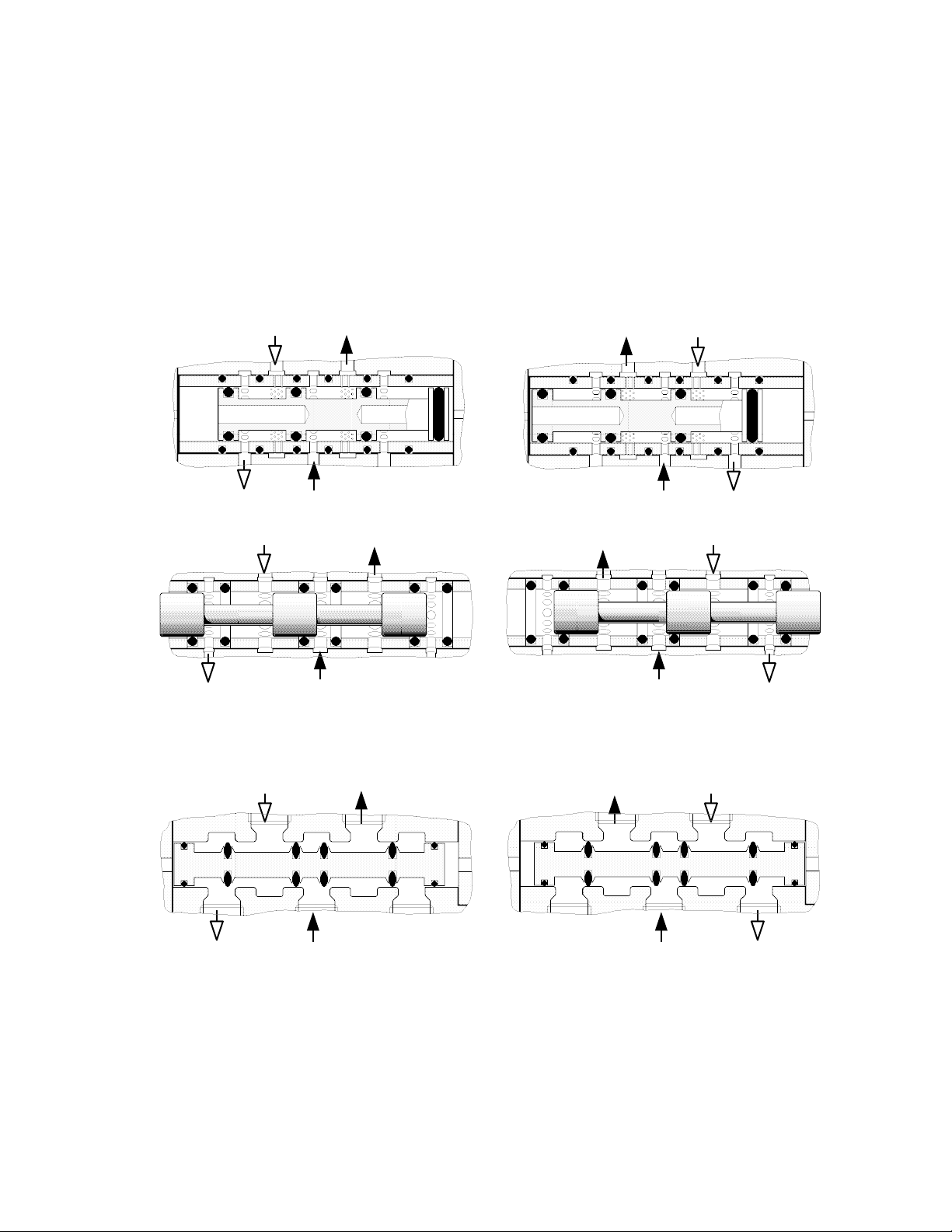
P N E U M A T I C T E C H N O L O G Y
S L I D I NG V A L VE S
Spool, rotary and plane slide valves use a sliding action to open and close ports.
Spo ol V alve s
A cylindrical spool slides longitudinally in the valve body with the air flowing at right angles to the spool
movement. Spools have equal sealing areas and are pressure balanced.
Ela s tom e r s eal
Common spool and seal arrangements are shown in Fig. 7.7 and 7.8. In Fig 7.7 O-rings are fitted in grooves on
the spool and move in a metal sleeve. Two of them are crossing output ports, which are therefore divided in a
great number of small holes in the sleeve.
BA
P
Fig. 7.7 Spool Valve with O-Rings on the spool, crossing the cylinder ports
The valve in Fig. 7.8 has seals fitted in the valve body, which are kept in position by means of sectional spacers
A
EA
Fig 7.9 shows a spool with oval rings. None of them have to cross a port, but just to open or close its own seat.
This design provides a leakage free seal with minimum friction and therefore an extremely long life, typically up to
50 million cycles.
P
A
EA
P
EBEA
B
EB
Fig. 7.8 Spool Valve with seals in the housing
B
EB
Fig. 7.9 Valve with oval ring spool
Meta l Se a l
Lapped and matched metal spool and sleeve valves have very low frictional resistance, rapid cycling and
exceptionally long working life, up to 200 million cycles. Even with a minimal clearance of 0.003 mm, a small
internal leakage rate of about one l/min occurs. This has no consequence as long as the cylinder does not need to
be held in position by a 5/3 valve with closed center for a long period of time.
DO NOT COPY WITHOUT WRITTEN PERMISSION – 82 –
Page 89
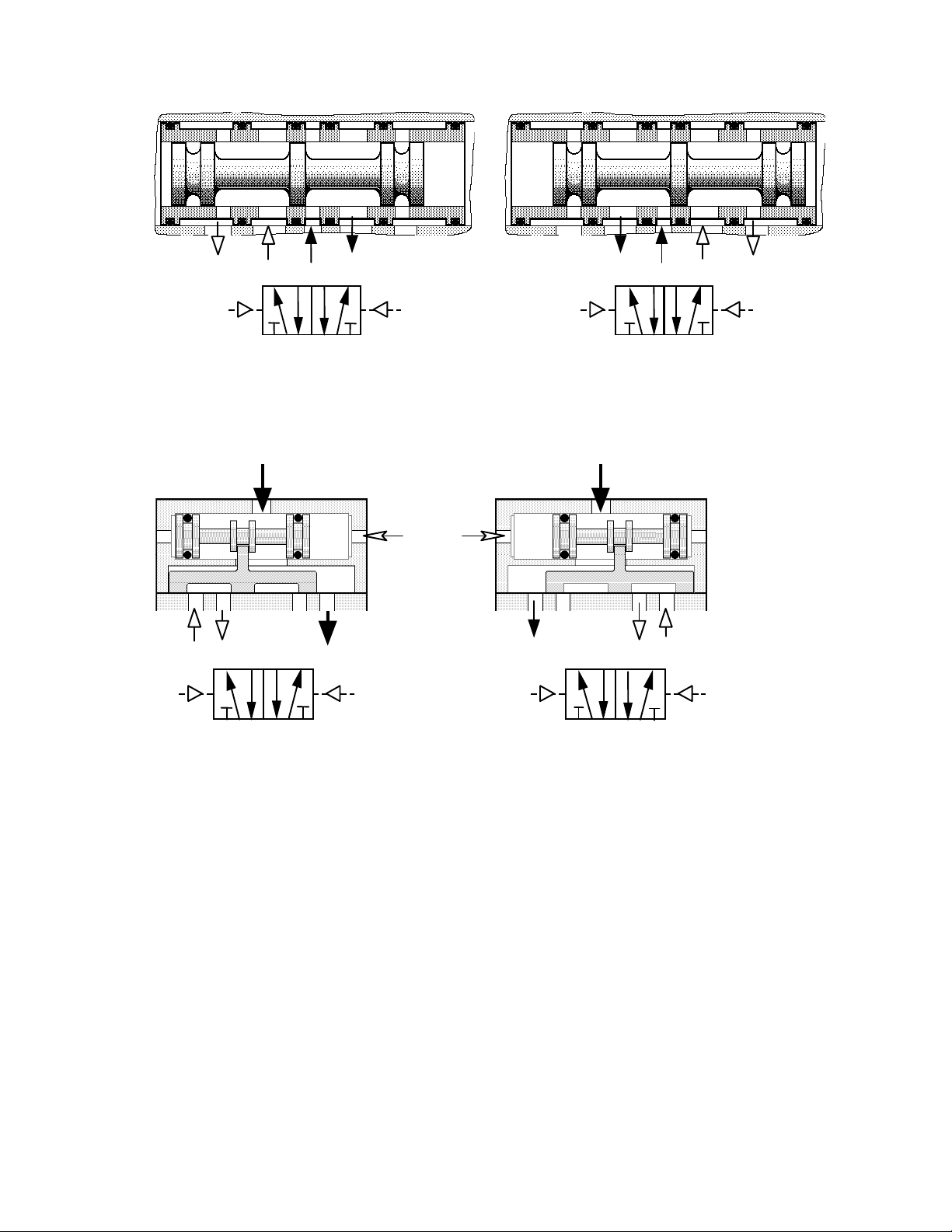
P N E U M A T I C T E C H N O L O G Y
4 2 1
3
4 2
1
5
3
14
12
4
2
1 5 3
14
12
P
B EA EB
PA
PB
A
P
A
B EA EB
PA
PB
A
A B P EA EB
PA
PB
A B
P
EA EB PA
PB
5
3
ISO Symbols
ISO Labels
Fig. 7.10 Principle of the seal-less Spool and Sleeve Valve
Pla n e S lid e Val v e
Flow through the ports is controlled by the position of a slide made of metal, ceramic, nylon, or other plastic.
The slide is moved by an elastomer (rubber) sealed, air operated spool.
ISO Symbols
NFPA label
Fig. 7.11 5/2 Plane Slide Valve
DO NOT COPY WITHOUT WRITTEN PERMISSION – 83 –
Page 90
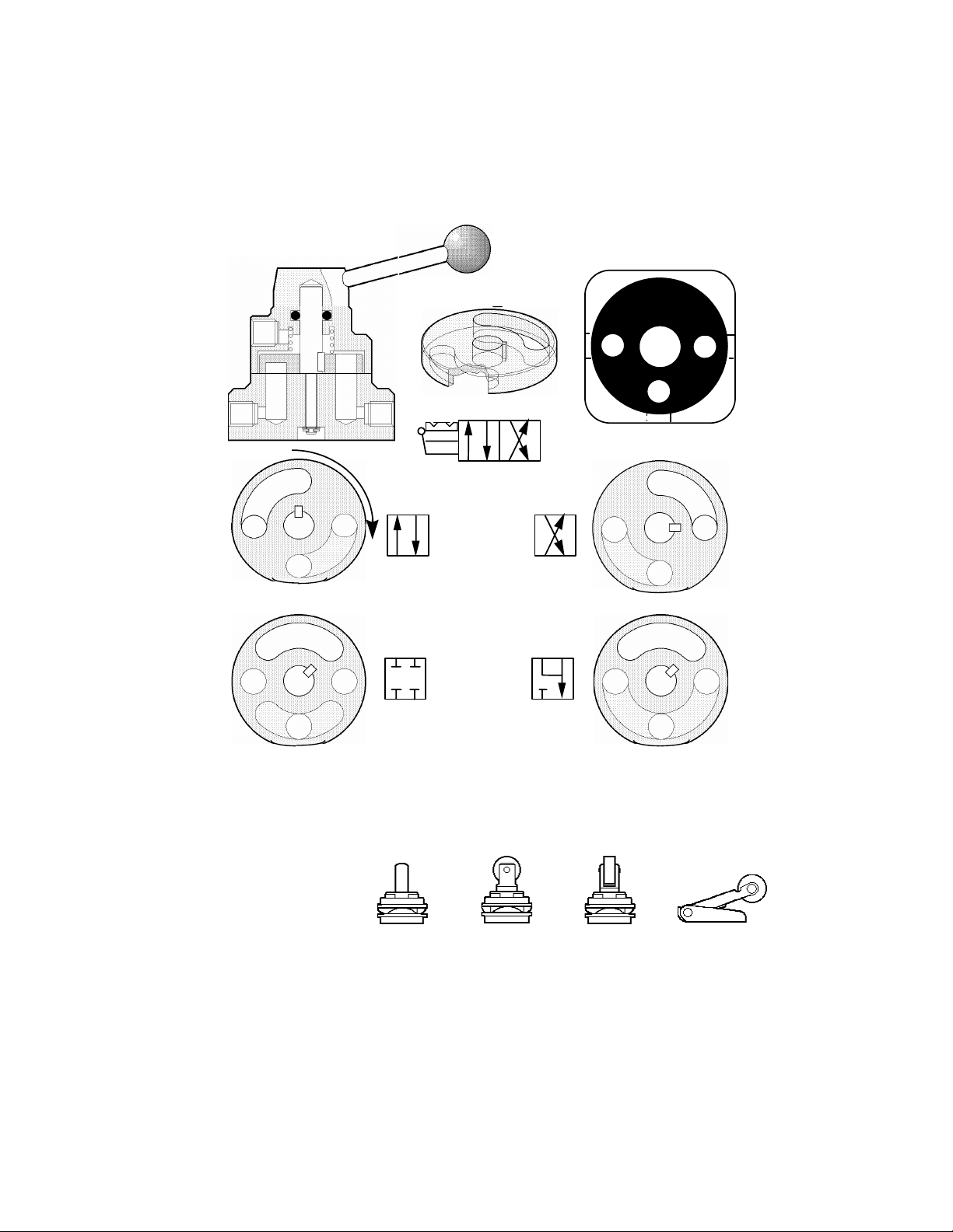
P N E U M A T I C T E C H N O L O G Y
A
B
EX
EX
A
B
ISO
A
B
EX P A B EX P
A B
EX P
A B
EX P
P
A
B
A
EX
EX
EX
A
A
B
B
B
Plunger
Straight Roller
Square Roller
Roller Lever
Ro t ary Valv e s
A metal-ported disc is manually rotated to interconnect the ports in the valve body. Pressure imbalance is
employed to force the disc against its mating surface to minimize leakage. The pressure supply must be above the
disc, or leakage will occur. In practice, this means that this type of valve must be plumbed as specified.
A B
P R
Fig 7.12 Section through a Rotary Disc Valve and a disc for a 4/3 function with closed center
VALVE OP ERATI ON
M E C H AN I C A L O P E R A T IO N
On an automated machine,
mechanically operated valves can
detect moving machine parts to
provide signals for the automatic
control of the working cycle.
The main direct mechanical
operators are shown in Fig. 7.13
DO NOT COPY WITHOUT WRITTEN PERMISSION – 84 –
Fig 7.13 The main Mechanical Operators
Page 91
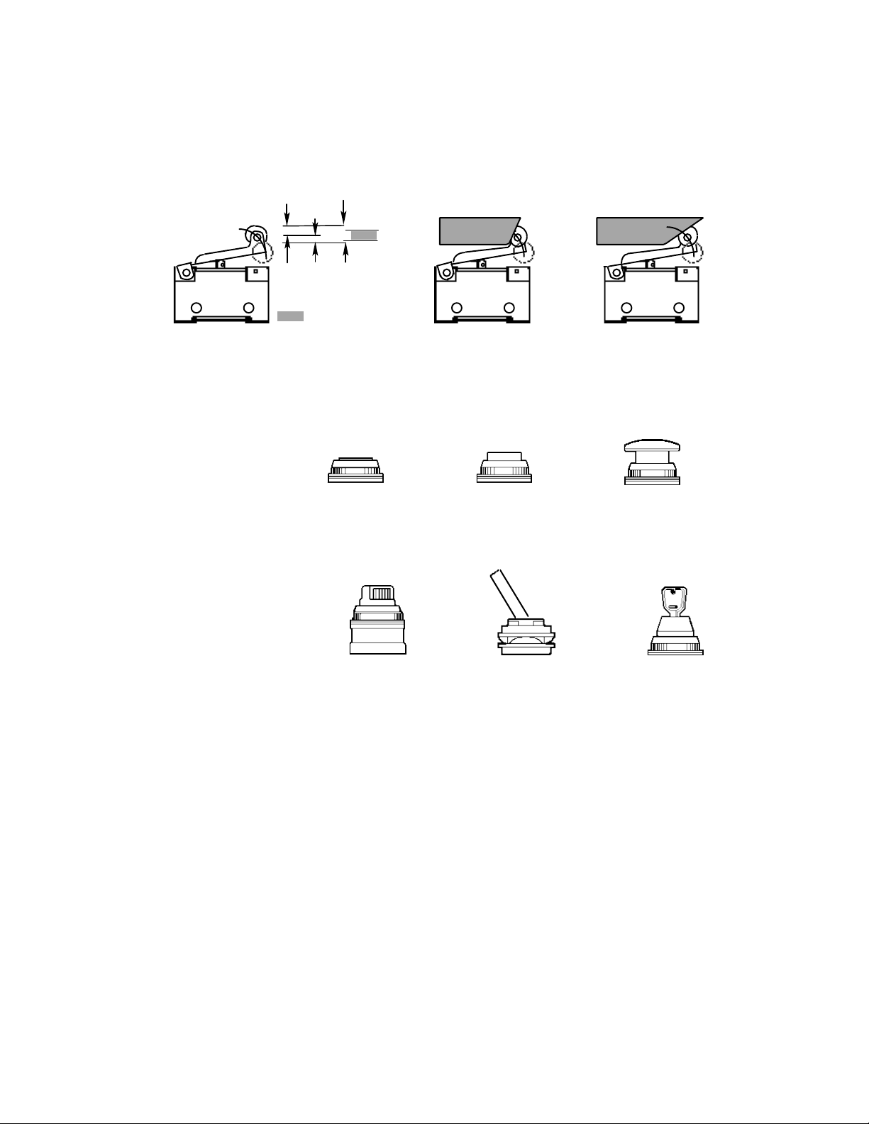
P N E U M A T I C T E C H N O L O G Y
Yes
Car e wh en u sin g Ro ller Lev ers
Special care must be taken when using cams to operate roller lever valves. Fig. 7.14 illustrates this: the utilized
portion of the rollers total travel should not go to the end of stroke. The slope of a cam should have an angle of
about 30°; steeper slopes will produce mechanical stresses on the lever.
PT. OT. TT.
NO !
PT: Pre-travel
OT.: Over Travel
TT.:Total
Roller Stroke to
be utilized
Fig. 7.14 Care with Roller Levers and Cams
The one-way roller (or idle return roller) will only operate when the control cam strikes the actuator when
moving in one direction. In the reverse direction the roller collapses without operating the valve.
M A N UA L O PE R A T IO N
Manual operation is generally
obtained by attaching an operator
head, suitable for manual control,
onto a mechanically operated
valve.
Flush Raised Mushroom
Fig. 7.15 The main monostable Manual Operators
Manually operated, monostable (spring returned) valves are generally used for starting, stopping and otherwise
controlling a pneumatic control unit.
For many applications it is
more convenient if the valve
maintains its position. Fig. 7.16
shows the more important types
of bi-stable manual operators
Rotating Knob Toggle Key
Fig. 7.16 Bi-stable Manual Operators
DO NOT COPY WITHOUT WRITTEN PERMISSION – 85 –
Page 92
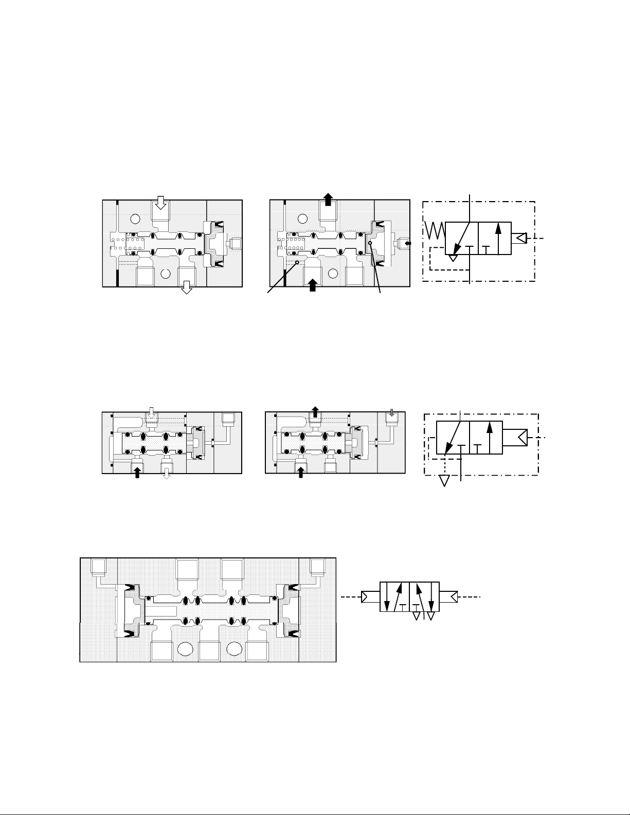
P N E U M A T I C T E C H N O L O G Y
A
P
R
Air connection for
A
P
R
AAP
R
P
R
PB PA A B
P EA EB
A
B
EB
NFPA
AI R O P E R AT IO N
Directional control valves, used as “Power Valves”, should be located as close as possible to its actuator and
be switched by remote control with a pneumatic signal.
A monostable air operated valve is switched by air pressure acting directly on one side of the spool or on a
piston and returned to its normal position by spring force. The spring is normally a mechanical spring, but it can
also be an “air spring” by applying supply pressure to the spool end, opposite to the pilot port, or a combination of
A
Pilot
Input
R P
spring assistance
Piston with twice the area
of the spool at spring side
Fig. 7.17 3/2 Air operated Valve, with air assisted spring return
Air assisted spring return gives more constant switching characteristics, and higher reliability.
In Fig 7.18 an air spring is provided through an internal passage from the supply port to act on the smaller
diameter piston. Pressure applied through the pilot port onto the larger diameter piston actuates the valve.
This method of returning the spool is often used in miniature valves, as it requires very little space
Pilot Input Pilot Input A
R P
ISO Symbol
Fig 7.18 Air operated 3/2 Valve with air spring return
The air-operated valves discussed so far have been single pilot or monostable types, but the more common air
operated valve for cylinder control has a double pilot and is designed to rest in either position (bi-stable).
PA
PB
P EA
Fig. 7.19 Bi-stable, air operated 5/2 Valve
In Fig. 7.19, a short pressure pulse has last been applied to the pilot port "PB", shifting the spool to the right
and connecting the supply port "P" to the cylinder port "B". Port “A" is exhausted through "EA". The valve will
remain in this operated position until a counter signal is received. This is referred to as a ‘memory function’.
DO NOT COPY WITHOUT WRITTEN PERMISSION – 86 –
Page 93
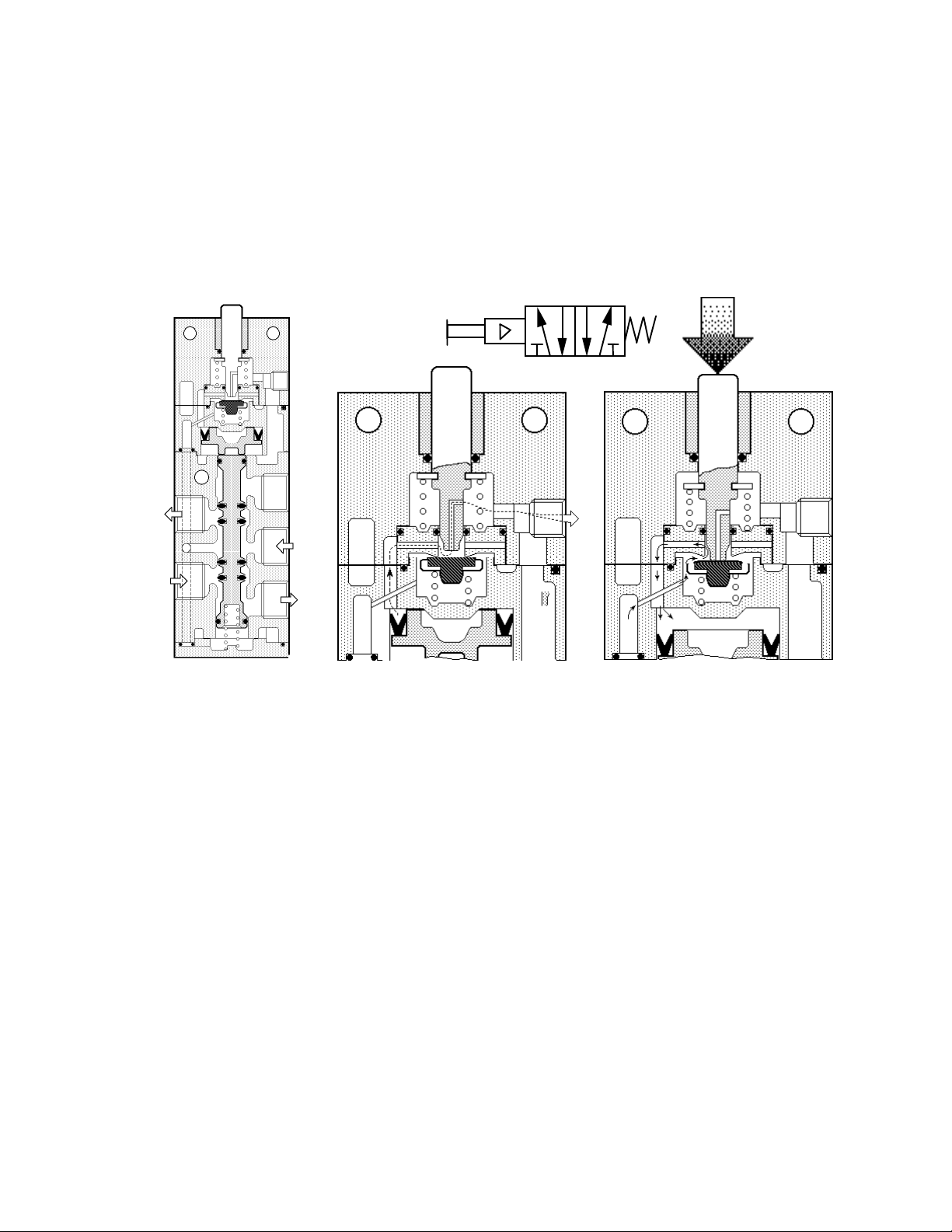
P N E U M A T I C T E C H N O L O G Y
B
b c
EA
A
P
Bi-stable valves hold their operated positions because of friction, but should be installed with the spool
horizontal, especially if the valve is subjected to vibration. In the case of metal seal construction, the positions
may be locked by a detent.
Pil o te d Op e rat i on
A direct operation occurs when a force, applied to a push button, roller or plunger, moves the spool or poppet
directly. With indirect or “piloted” operation, the external operator acts on a small pilot valve that in turn switches
the main valve pneumatically. The external operator can be mechanical, as shown below in Fig 7.20, or electrical,
as shown in Fig. 7.23.
NFPA Symbol:
B
F
P EB
EB
A
EA
a
Fig 7.20 Indirect Mechanical Operation
Fig. 7.20 a shows a 5/2 Valve with indirect or “piloted” mechanical operation in its normal position. The
magnified details in b and c show the pilot part in normal (b) and in operated position (c).
DO NOT COPY WITHOUT WRITTEN PERMISSION – 87 –
Page 94
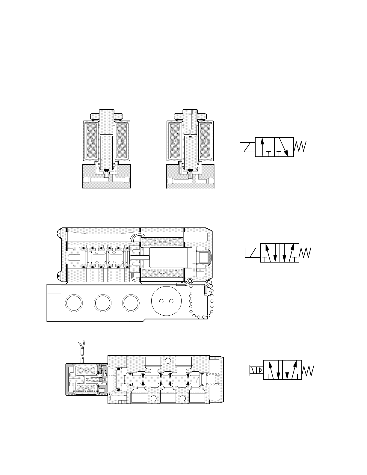
P N E U M A T I C T E C H N O L O G Y
b
P
ISO Symbol
2 4 1 3 5
A P R1 R2
S O L E N O ID O P E R AT I O N
Electro pneumatically and electronically controlled systems are typically discussed separately and it is sufficient
at this stage only to consider the electrical operation of directional control valves.
In small size solenoid valves, an iron armature moves inside an airtight tube. The armature is fitted with an
elastomer poppet and is lifted from a supply seat in the body by the magnetic force of the energized coil. See
Figure 7.21a.
A
R
JIS Symbol
a
Fig 7.21 a: 2/2, b: 3/2 direct solenoid, spring return, poppet type valve.
A 3/2 valve has also an exhaust seat on top and the armature an elastomer poppet in its top end. (Fig. 7.21 b)
Directly operated 5/2 solenoid valves rely on the electromagnetic force of the solenoid to move the spool (Fig
7.22). It can only be a seal-less lapped spool and sleeve type without friction.
Fig. 7.22 Direct solenoid operated 5/2 Valve with spring return
To limit the size of the solenoid, larger and elastomer sealed valves have indirect (piloted) solenoid operation.
B
JIS Symbol
Fig. 7.23 5/2 Monostable Solenoid Valve with elastomer bonded spool
DO NOT COPY WITHOUT WRITTEN PERMISSION – 88 –
Page 95
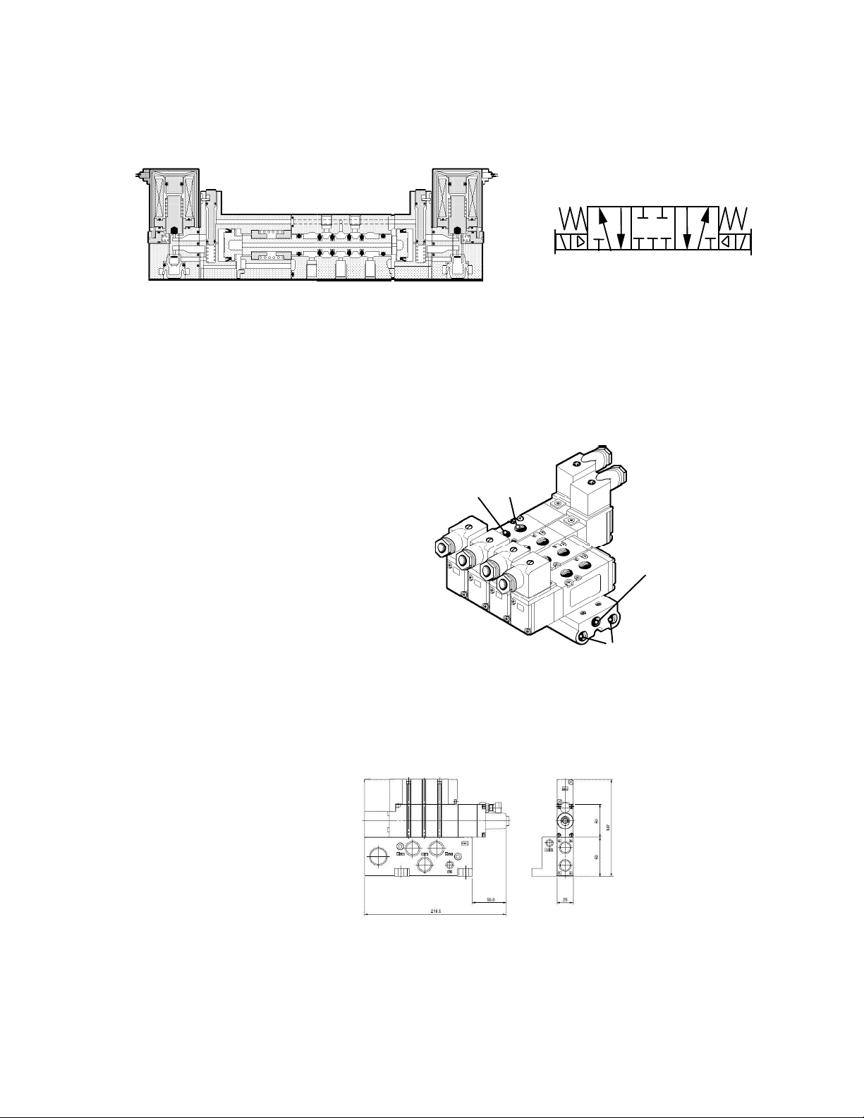
P N E U M A T I C T E C H N O L O G Y
ISO Symbol
1
Common
Supply
Common
Exhausts for
A and B Ports
Cylinder Ports
A and B
The 5/3 valve has a third (center) position to which it will return, by means of springs, when both solenoids are
de-energized. (Fig 7.24)
2 4
3
5
Fig 7.24.Pilot operated 5/3 Solenoid Valve with closed center and spring centering valve mounting
D I R E C T P I P I N G
The most common method of connection to a valve is to screw fittings directly into the threaded ports of a so-
called body ported valve. This method requires one fitting for each cylinder, pilot and supply port and one silencer
for each exhaust port. All the valves shown previously are body-ported types, except Fig. 7.22, which is sub base
mounted.
M A N IF O L D S
Manifolds have common supply and exhaust
channels for a given number of body-ported
valves. The outputs are connected separately to
each valve.
Fig. 7.25 shows a manifold with four valves of
different functions: a 5/3, a bi-stable and two
monostable types of the same series.
A manifold should be ordered to accommodate
the required number of valves, extension is not
possible, but using a blanking kit can seal spare
positions.
With 5 or more valves it is recommended that
air is supplied and silencers mounted at both ends.
Fig. 7.25 Typical Manifold
S U B BA S E S
Valves with all of their ports on one
face are designed to be gasket
mounted on a sub base, to which all
the external connections are made.
This allows quick removal and
replacement of a valve without
disturbing the tubing. Generally, a
base mounted valve has a slightly
better flow capacity than a bodyported valve of the same type. Fig.
7.22 shows a typical base mounted
valve
DO NOT COPY WITHOUT WRITTEN PERMISSION – 89 –
Fig. 7.26 Single Sub base
Page 96
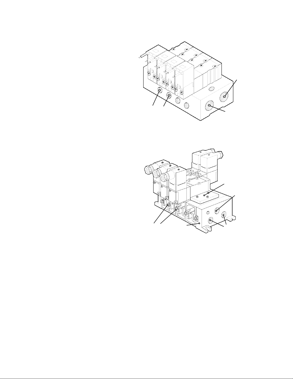
P N E U M A T I C T E C H N O L O G Y
M U L T I P L E S U B B A S E S
In a similar way to the manifold,
multiple sub bases supply and exhaust a
number of valves through common
channels. Also the cylinder ports are
provided in the sub base.
Multiple sub bases also have to be
ordered for the required number of valves
and are able to be blanked off in the
same way as manifolds.
Fig. 7.27 shows a manifold with four
base-mount types 3/2 Solenoid Valves.
The common exhaust ports are to be
equipped with Silencers, preferably on
both ends to avoid backpressure. This is
not only recommended for sound
elimination but also for dust protection.
G A N G E D S U B B A S E S
Ganged Sub Bases are assemblies of
individual bases, which allow any
reasonable number to be assembled into
one unit. This system has the advantage of
allowing extension or reduction of the unit if
the system is altered, without disturbing the
existing components. There is still the
option to blank off positions, if required.
Fig. 7.28 shows a typical assembly,
equipped with one monostable and two bistable solenoid valves and a blanking plate.
The individual sub bases are hold together
with clamps. Other constructions may also
have bolts or tie rods for the purpose. O
Rings, inserted in grooves around the
channels, provide a leakage free
connection of supply and exhaust channels
from end to end.
Common
Supply
Valve Outputs
(A Ports)
Common
Exhaust
Fig. 7.27 Multiple Sub Base with four 3/2 Valves
Blanking
Plate
Supply
ExhaustsClamps End Plate
Fig. 7.28 Ganged Sub Base with three valves and one blanked
position.
VALVE SI ZING
I N D I C AT I O N S FO R F L O W C AP A C I T Y
Port dimensions do not indicate the flow capacity of the valve. The selection of the valve size will depend on the
required flow rate and permissible pressure drop across the valve.
The manufacturers provide information on the flow capacity of valves. Flow capacity is usually indicated as the
so called “standard flow” Qn in liters of free air per minute at an inlet pressure of .6 MPa and an outlet pressure of
.5 MPa, or with a flow factor, Cv or kv, or with the equivalent Flow Section “S”. These factors require formulae or
diagrams to define the flow under various pressure conditions.
The Cv factor of 1 is a flow capacity of one US Gallon of water per minute, with a pressure drop of 1 psi at
60F.
The kv factor of 1 is a flow capacity of one liter of water per minute with a pressure drop of .1 MPa at 20C.
DO NOT COPY WITHOUT WRITTEN PERMISSION – 90 –
Page 97
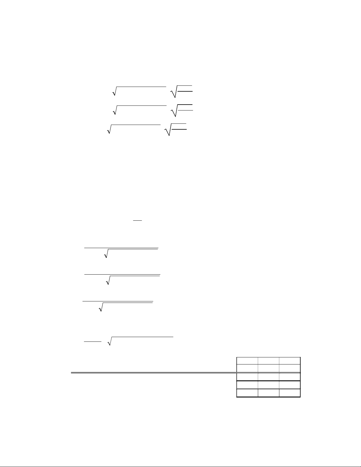
P N E U M A T I C T E C H N O L O G Y
67.22
The equivalent Flow Section “S” of a valve is the flow section in mm2 of an orifice in a diaphragm, creating
the same relationship between pressure and flow.
All three methods require a formula to calculate the airflow under given pressure conditions. They are as
follows:
Q = 4000 · Cv · pp •)1013.2( ·
Q = 279.4 · kv · pp •)1013.2( ·
Q = 222 · S · pp •)013.12( ·
273 +
273 +
273
273 +
273
273
Where Cv, kv =Coefficients of flow
S =Equivalent Flow Section in mm2
Q = Flow rate normal liters/min (nl/min)
p2 = Outlet pressure needed to move load (MPa)
Ap or p = Permissible pressure drop (MPa)
= Air temperature in *C
3
With this, the dimension of “S” is
m
Pa
To find the flow capacity, these formulae are transformed as follows:
Q
Q
Q
pp
•)1013.2(•4000
pp
•)1013.2(•4.279
pp
•)1013.2(•222
Cv =
Kv =
S =
In Imperial Units:
Q
Cv =
scfm
)•2/(
ppTemp
psiarankine
1 Cv = 1 kv =
The normal flow Qnl for other various flow capacity units is: 981.5 68.85 54.44
The Relationship between these units is as follows:
0.07
0.055 0.794
1
1 S =
14.3 18
1.26
1
1
Note: The outcome of this calculation gives in fact not the required flow capacity of the valve, as we simply stated above, but
for the assembly of the valve and the connecting tubes and filling. To get as much flow capacity, that of the valve has
to be higher. How much higher?
DO NOT COPY WITHOUT WRITTEN PERMISSION – 91 –
Page 98
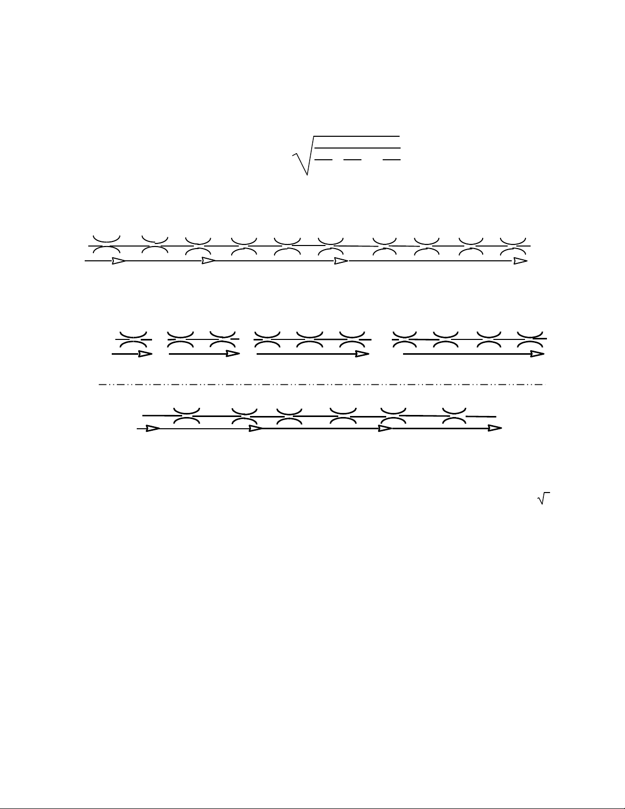
P N E U M A T I C T E C H N O L O G Y
Ori fic e s in se r i es c onn ect i on
Before we can determine the sizes of valve and tubing, we have to look at how pressure drops over a number
of subsequent orifices in series. The formula for the resulting “S” is (or substitute Cv for “S” in this equation):
S
total
=
1
S1
1
1
+
S2
+ …
2
2
Sn
1
2
To avoid unnecessarily dealing with such formulae we look for a thumb rule. Fig. 7.29 and Fig. 7.30.A show the
relationship between a number of orifices in series connection and the resulting flow.
Cv=1 Cv=1 Cv=1 Cv=1
Cv=1 Cv=1 Cv=1 Cv=1
Cv=1 Cv=1
C
=1
C
vsys
=.70 C
vsys
C
=.58
vsys
=.50 C
vsys
=.45 C
vsys
=.41 C
vsys
vsys
=.38 C
vsys
=.35 C
vsys
=.33 C
vsys
=.32
Fig. 7.29 In Series circuit, all devices having a Cv of 1 and the resulting impact on the circuit’s overall C
Cv=1
Cv=1.4
A
=1
C
vsys
Cv=1
Cv=1.4
=1.0
C
vsys
Cv=2
Cv=1.73
Cv=3
Cv=1.73 Cv=1.73 Cv=2 Cv=2
=1.0
C
vsys
Cv=4
Cv=5
C
Cv=6
Cv=2 Cv=2
=1.0
vsys
B
v
=1
C
vsys
=0.89
C
vsys
=0.86
C
vsys
=0.84
C
vsys
=0.83
C
vsys
=0.82
C
vsys
Fig. 7.30 A, B Orifices in series connection and resulting flow
Returning to our topic, we can say that it is most obvious to have about the same flow capacity for the valve
and the connecting tube with its fittings. We consider these parts as two equal flow capacities in series connection
and to have the required calculated flow through both parts, the required Cv has to be multiplied with 1.4 ( 2 ) to
allow for adiabatic change. It should also be noted that the controlling orifice for an air cylinder is not always
defined by its port size. Many times a manufacturer will control a cylinder’s maximum velocity by using a restrictive
orifice --- that will, in turn, define the flow capability of the cylinder.
Observe that in Fig. 7.30B, the smallest Cv determines the flow for the system just as the weakest link
determines the strength of a chain. Therefore, when trying to improve upon a system’s flow capability (to make a
cylinder respond more quickly), any productive change must be made to the most restrictive orifice.
The smallest orifice determines the flow for the circuit; system flow is smaller than the flow allowed by the
smallest orifice.
DO NOT COPY WITHOUT WRITTEN PERMISSION – 92 –
Page 99
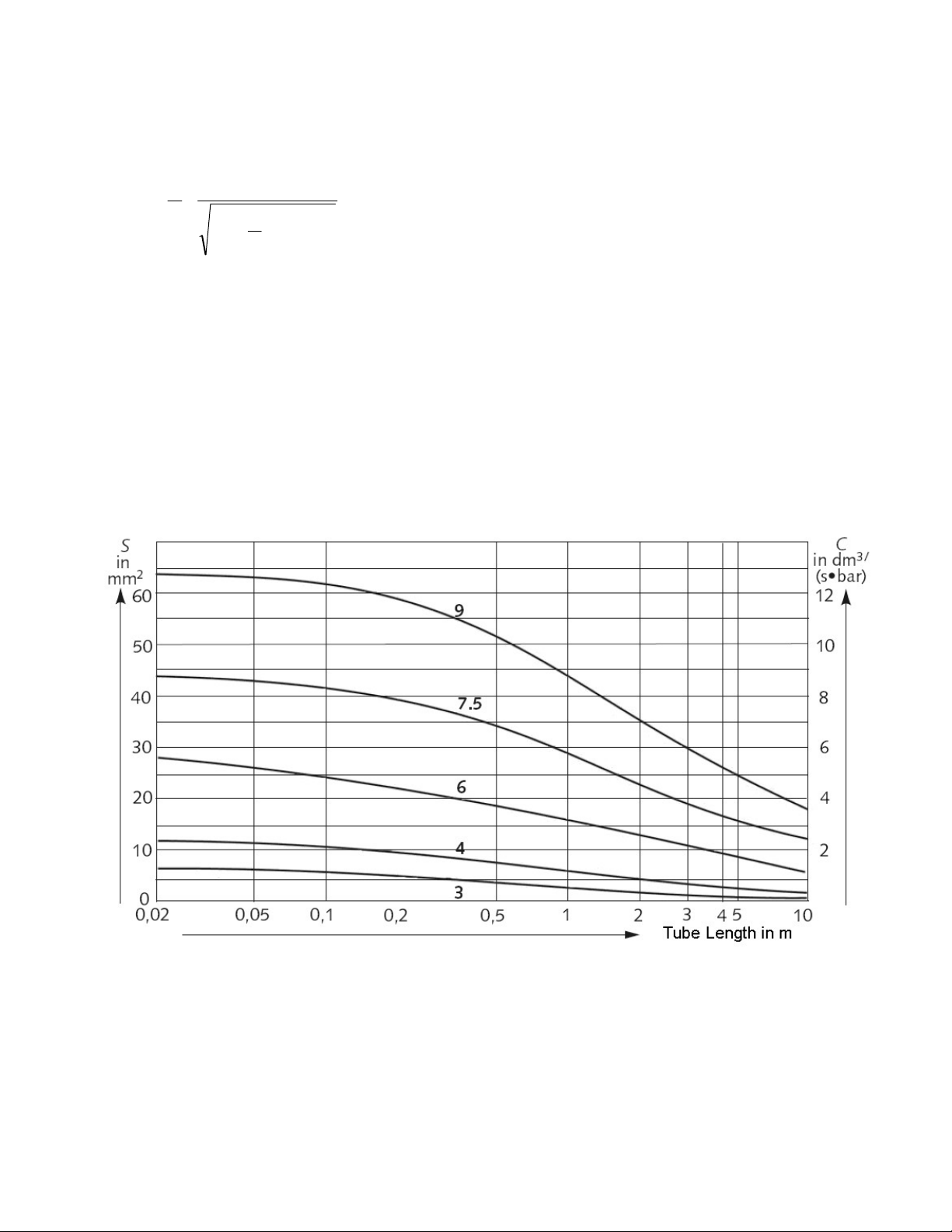
P N E U M A T I C T E C H N O L O G Y
F L O W C AP A C IT Y O F T U B E S
Still unknown is the flow capacity of tubes and fittings. The formula for the equivalent section of a tube is:
2
dS
4
S = Equivalent Flow Section [mm]
d = Diameter [mm]
l = Lengths [m]
Use one of the following coefficient of friction depending on the piping material:
Steel piping
Plastic, rubber and copper piping
You can by-pass this calculation by reading the equivalent Section of nylon tubes, normally used for
pneumatics, from the diagram 7.31. The bold numbers above the curves indicate the ID of the tubes.
1
l
d
3
110
31.0
=
=
0307.0
0197.0
d
31.0
d
Fig. 7.31 the equivalent Flow Section S in mm2 of the current tube sizes and length
DO NOT COPY WITHOUT WRITTEN PERMISSION – 93 –
Page 100
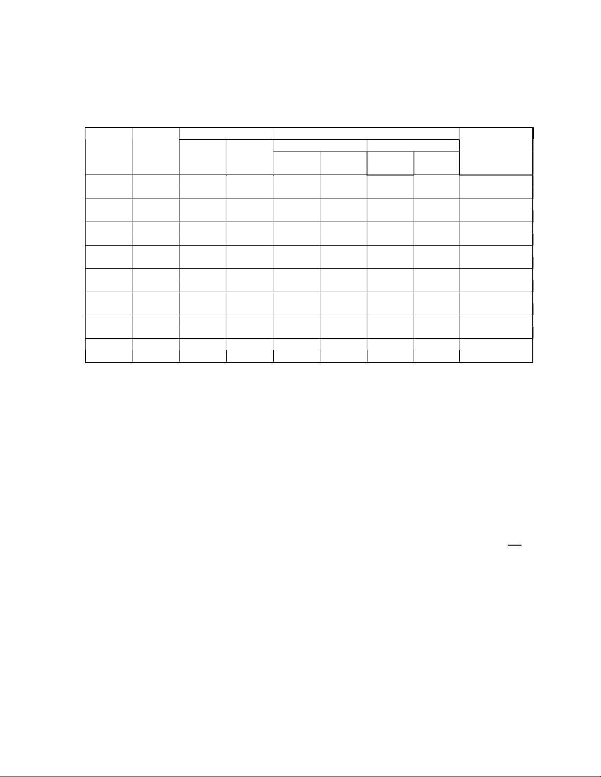
P N E U M A T I C T E C H N O L O G Y
The Flow Section of fittings has to be specified in the catalogues. The total of a tube length with its two fittings
can be calculated with the formula above. To reduce the need of its use to exceptions, you can find the sections
for the most current tube assemblies in Table 7.32.
Tube Material
Dia.
(mm)
4 x 2.5 N,U 1.86 3.87 1.6 1.6 1.48
5.6 4.2 3.18
6 x 4 N,U 6.12 7.78 6 6 3.72
13.1 11.4 5.96
8 x 5 U 10.65 13.41 11 (9.5) 11 6.73
18 14.9 9.23
8 x 6 N 16.64 20.28 17 (12) 16 10.00
26.1 21.6 13.65
10 x 6.5 U 20.19 24.50 35 (24) 30 12.70
29.5 25 15.88
10 x 7.5 N 28.64 33.38 30 (23) 26 19.97
41.5 35.2 22.17
12 x 8 U 33.18 39.16 35 (24) 30 20.92
46.1 39.7 25.05
12 x 9 N 43.79 51.00 45
58.3 50.2 32.06
1 m 0.5 m Insert type One Touch 0.5 m tube +
Straight Elbow Straight Elbow 2 straight
Table 7.32 Equivalent Flow Section of current tube connections
Length
Fittings
(27) 35
Total S Value
fittings
29.45
Table 7.32 shows the flow capacity of current tubes and fittings, based on so called “push-in” or “One Touch”
fittings (Fig. 4.26), having the same inner diameter as the tube. Insert fittings (Fig. 4.25) reduce the flow
considerably, especially in smaller sizes, and should be avoided for pneumatics.
Val v es w it h Cy l ind e rs
We now return to the cylinder consumption. This is first of all the peak flow, depending on speed.
Secondly, we have to define the allowable pressure drop, a major figure in calculating the valve size. An
assumption of average velocity may be made, since maximum flow is achieved at a pressure drop of
approximately 46% --- for our purposes 23% is the maximum allowable pressure drop (half of 46%) --- the NFPA
states a 15% maximum pressure drop is desired.
The actual size of the valve has to be much higher than the theoretical value, to compensate for the additional
pressure drop in the connecting tubes and fittings, as discussed above. But if the maximum flow is determined
(limited) by the fittings and tubing part of the circuit --- changing the valve for a larger flow capability will not have
an effect. E.g. if the valve has a Cv of 2 and the tubing and fittings collectively have a Cv of 1 --- the system will not
be improved by a valve with a Cv 4); note Fig. 7.29.2.
To make things easy, all the calculations mentioned before on this subject have been condensed into Table
7.33, which gives you the required equivalent section S for the valve and for the selection of a suitable tube and
fittings assembly from Table 7.32. The table is based on a supply pressure of .6 MPa (approx. 90 psig) and a
pressure drop of .1 MPa (15 psig) through the valve. It includes also the loss by adiabatic pressure change and the
temperature coefficient for 20°C. Usually this will suffice for most real world applications. Note that the values
shown on this chart have mathematically taken the calculated required system Cv, and multiplied by two in order to
account for the valve, tubing, and two fittings.
DO NOT COPY WITHOUT WRITTEN PERMISSION – 94 –
 Loading...