

Page 1
Survival Guide
“The answers to all the crazy Pneumatic and Fluid Power Questions”
NC162-D
Page 2

Fast
Delivery
Regional Distribution Centers
Provide local inventory
Engineered
Specials
We offer competitive special products.
We meet customer's request
Cost
Savings
1. Low Power
2. Energy Saving
3. Space Saving
Made to
Order
Largest
Choice
12,000 basic models & 700,000 variations.
Page 3

Table of Contents
Unit Conversions ........................................................................................................ 1
Fractional / Decimal / Millimeter Conversion Chart
Pressure Conversions
Cylinder Force Chart
Cylinder Speed vs Flow Chart
Formulas
Valve Sizing
........................................................................................................................ 6
................................................................................................................ 6
Valve Selection
Vacuum Cup Sizing
Sizing Vacuum Ejectors
Pipe Thread Quick Reference
Installation Guide for Valves
Directional Control Valves
Product Data Codes
Cylinder Part Number Building Information
Crossing Over a Cylinder
Valve Part Number Building Information
........................................................... ..... ........... ..... ........... ..... . 3
........................................................................................................... 4
........................................................................ 5
........................................................................................................ 7
................................................................................................ 8
..................................................................................... 8 to 10
........................................................................ 11
................................................................................ 12
...................................................................... 13 & 14
................................................................................................ 15
..................................................... 16
................................................................................................ 17
............................................................ 18
................................ 2
Vacuum Order Sheet ........................................................................................................... 19
Auto Switches
Pressure Switches and their Simplified Operation
NEMA Ratings (Electrical Enclosures)
IP Ratings (Electrical Enclosures)
How to Order (Series KQ2- New)
FRL Cheat Sheet
........................................................................................................................ 20
................................ 21
........................................................ 22
........................................................................... 22
............................................................................ 23
................................................................................................................ 24
Page 4
Unit Conversions
Metric to English
Multiply
∇
Length:
µm ............................. 0.0394 .................... mil
mm ...........................0.0394 .................... in
cm ............................. 0.3937 .................... in
m ................................ 3.2810 .................... ft
Area:
2
mm
........................ 0.0016 .................... in
2
cm
........................ 0.1550 .................... in
2
m
........................ 10.764 .................... ft
Volume:
3
mm
........................
cm3 (cc) ................ 0.0610 ............................ in
3
m
............................ 35.314 ............................ ft
l ................................ 0.0353 ............................ ft
l ................................ 0.2642 ........................ gal (US)
Weight:
g .............................. 0.0353 ........................... oz
kg ........................... 2.2046 ........................... lb
Force:
gf .............................. 2.205x10
kgf ........................ 2.2046 ........................... lbf
N .............................. 0.2248 ........................... lbf
Torque:
N•m ........................ 0.7375 ........................... ft•lb
kg•m ........................ 7.223 .............................. ft•lb
Pressure:
mm (H2O)............ 0.00142 ..................... psi
mm (Hg) ............... 0.0193 ........................ psi
torr ........................ 0.0193 ........................ psi
kPa ........................ 0.145 ........................... psi
bar ........................... 14.5 ........................... psi
2
kgf/cm
............... 14.224 ........................ psi
MPa ..................... 145.0 ........................... psi
Energy:
N•m ...........................0.7375 ........................... ft•lb
J .................................0.7375 ........................... ft•lb
MJ ..............................0.2778 ........................... kWh
Power:
W ..............................0.7376 ........................... ft•lb/s
kW
...........................1.341 .............................. hp
Flow Rate:
l/min ANR ............0.035 .............................. SCFM
Flow Coefficient:
2
mm
.......................... 0.0556 ........................... Cv
Temperature: °F = (1.8 x °C) + 32
1
By
∇
6.10x10
-5
.................... in
-3
.................. lbf
To Obtain
English to Metric
∇
∇
Length:
mil ........................... 25.4 ........................... µm
in .............................. 25.4 ........................... mm
in .............................. 2.54 ........................... cm
ft .............................. 0.3048 ..................... m
Multiply
Area:
2
2
2
3
3
3
3
2
in
........................... 645.16 ..................... mm
2
in
........................... 6.4516 ..................... cm
2
ft
........................... 0.0929 ..................... m
Volume:
3
in
........................... 16387........................ mm
3
in
........................... 16.387 ..................... cm
3
ft
........................... 0.0283 ..................... m
3
ft
........................... 28.329 ..................... l
gal (US) ............... 3.785 ........................ l
Weight:
oz ........................... 28.349 ..................... g
lb .............................. 0.4536 ..................... kg
Force:
lbf ........................... 453.6 ........................ gf
lbf
........................... 0.4536 ..................... kgf
........................... 4.4482 ..................... N
lbf
Torque:
ft•lb........................... 1.3559 ..................... N•m
ft•lb ........................ 0.1383 ..................... kg•m
Pressure:
in (H2O) ............... 0.00254 .................. kgf/cm
in (Hg) .................. 0.03518 .................. kgf/cm
psi ........................... 6.8947 ..................... kPa
psi ........................... 0.06894 .................. bar
psi ........................... 0.0703 ..................... kgf/cm
psi ........................... 0.00689 .................. MPa
Energy:
ft•lb........................... 1.356 ........................ N•m
ft•lb........................... 1.356 ........................ J
kWh ........................ 3.6 .............................. MJ
Power:
ft•lb/s........................ 1.356 ........................ W
hp
.............................. 0.7457 ..................... KW
Flow Rate:
SCFM..................... 28 .3 .................. l/min ANR
Flow Coefficient:
Cv ........................... 18................................. mm
Temperature: °C=5/9 (°F -32)
By
To Obtain
2
3
∇
2
3
2
3
(cc)
2
2
2
2
∇
Page 5
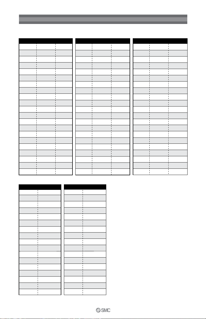
Fractional / Decimal / Millimeter Conversion Chart
1mm = 0.03937” 0.01” = 0.254mm 1” = 25.4mm
Inch Decimal mm
1/64
1/32
3/64
1/16
5/64
3/32
7/64
1/8
9/64
5/32
11/64
3/16
13/64
7/32
15/64
1/4
17/64
9/32
19/64
5/16
21/64
0.016
0.031
0.047
0.063
0.078
0.094
0.109
0.125
0.141
0.156
0.172
0.188
0.203
0.219
0.234
0.25
0.266
0.281
0.297
0.313
0.328
0.397
0.794
1.191
1.588
1.984
2.381
2.778
3.175
3.572
3.969
4.366
4.763
5.159
5.556
5.953
6.35
6.747
7.144
7.541
7.938
8.334
Inch Decimal mm
11/32
23/64
3/8
25/64
13/32
27/64
7/16
29/64
15/32
31/64
1/2
33/64
17/32
35/64
9/16
37/64
19/32
39/64
5/8
41/64
21/32
0.344
0.359
0.375
0.391
0.406
0.422
0.438
0.453
0.469
0.484
0.5
0.516
0.531
0.547
0.563
0.578
0.594
0.609
0.625
0.641
0.656
8.731
9.128
9.525
9.922
10.319
10.716
11.113
11.509
11.906
12.303
12.7
13.097
13.494
13.891
14.288
14.684
15.081
15.478
15.875
16.272
16.669
Inch Decimal mm
43/64
11/16
45/64
23/32
47/64
49/64
25/32
51/64
13/16
53/64
27/32
55/64
57/64
29/32
59/64
15/16
61/64
31/32
63/34
3/4
7/8
0.672
0.688
0.703
0.719
0.734
0.75
0.766
0.781
0.797
0.813
0.828
0.844
0.859
0.875
0.891
0.906
0.922
0.938
0.953
0.969
0.984
17.066
17.463
17.859
18.256
18.653
19.05
19.447
19.844
20.241
20.638
21.034
21.431
21.828
22.225
22.622
23.019
23.416
23.813
24.209
24.606
25.003
mm Inch
0.1
0.2
0.3
0.4
0.5
0.6
0.7
0.8
0.9
0.0039
0.0079
0.0118
0.0157
0.0197
0.0236
0.0276
0.0315
0.0354
1
0.0394
2
0.0787
3
0.1181
4
0.1575
5
0.1969
6
0.2362
7
0.2756
8
0.3150
mm Inch
9
10
11
12
13
14
15
16
17
18
19
20
21
22
23
24
25
0.3543
0.3937
0.4331
0.4724
0.5118
0.5512
0.5906
0.6299
0.6693
0.7087
0.7480
0.7874
0.8268
0.8661
0.9055
0.9449
0.9843
2
Page 6
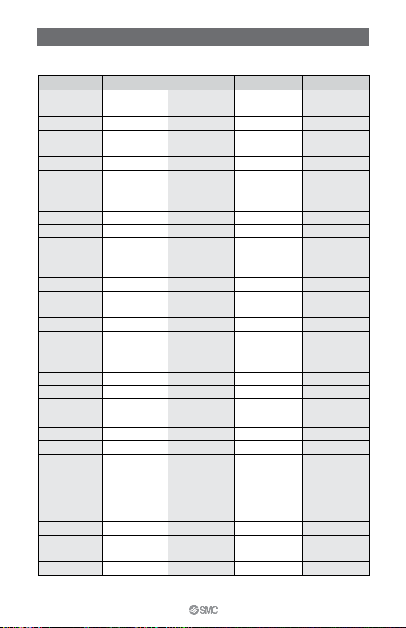
Pressure Conversions
PSI kgf/cm
4 .28 .03 28 0.28
10 .70 .07 69 0.69
12 .84 .08 83 0.83
15 1.1 .10 103 1.03
20 1.4 .14 138 1.38
22 1.5 .15 152 1.52
25 1.8 .17 172 1.72
29 2.0 .20 200 2.00
30 2.1 .21 207 2.07
35 2.5 .24 241 2.41
36 2.6 .25 248 2.48
41 2.9 .28 282 2.83
45 3.2 .31 310 3.10
49 3.4 .34 338 3.38
55 3.9 .38 379 3.79
59 4.1 .41 407 4.07
65 4.6 .45 448 4.48
70 4.9 .48 483 4.83
75 5.3 .52 517 5.17
80 5.6 .55 552 5.52
86 6.0 .59 593 5.93
90 6.3 .62 621 6.21
96 6.7 .66 662 6.62
100 7.0 .69 689 6.89
103 7.2 .71 710 7.10
104 7.3 .72 717 7.17
110 7.7 .76 758 7.58
115 8.1 .79 793 7.93
120 8.4 .83 827 8.27
125 8.8 .86 861 8.62
131 9.2 .90 903 9.03
135 9.5 .93 931 9.31
141 9.9 .97 972 9.72
145 10.2 1.0 1000 10.00
159 11.2 1.1 1096 10.96
215 15.1 1.48 1482 14.82
2
MPa kPa bar
3
Page 7
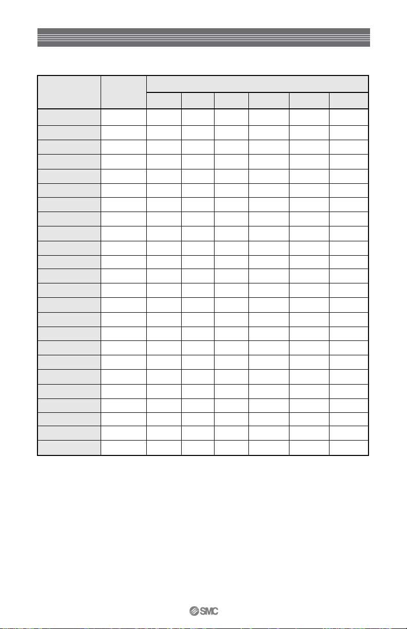
Cylinder Force Chart
Theoretical Force = Area x Pressure
Piston
Bore
1/4” (6mm)
8mm
3/8” (10mm)
5/8” (16mm)
3/4” (20mm)
1” (25mm)
1 1/8”
30mm
1 ¼” (32mm)
1 ½” (40mm)
1 ¾”
2” (50mm)
2 ½” (63mm)
3 ¼ (80mm)
4” (100mm)
4 ½”
5” (125mm)
140mm
6”
160mm
7” (180mm)
8” (200mm)
10” (250mm)
12”
Note: Do not forget to apply safety factor of 0.7 for horizontal and 0.5 for vertical cylinder orientation.
Area
(in2)
0.05
0.08
0.11
0.31
0.44
0.79
0.99
1.10
1.23
1.77
2.41
3.14
4.91
8.30
12.57
15.90
19.63
23.86
28.27
31.16
38.48
50.27
78.54
113.10
25 psi 50 psi 75 psi 100 psi 125 psi 150 psi
11
20
25
27
31
44
60
79
123
207
314
398
491
597
707
779
962
1257
1963
2827
Operating Pressure (psi)
2 lbf 4 lbf
2
3
8
4
6
15
22
39
50
55
61
88
120
157
245
415
628
795
982
1193
1414
1558
1924
2513
3927
5655
6
8
23
33
59
75
82
92
133
180
236
368
622
942
1193
1473
1790
2121
2337
2886
3770
5890
8482
5 lbf1 lbf
11
31
44
79
99
110
123
177
241
314
491
830
1257
1590
1963
2386
2827
3116
3848
5027
7854
11310
6 lbf
8
124
137
153
221
301
393
614
1037
1571
1988
2454
2983
3534
3896
4811
6283
9817
14137
10
14
38
55
98
7 lbf
12
17
46
66
118
149
164
184
265
361
471
736
1244
1885
2386
2945
3579
4241
4675
5773
7540
11781
16965
4
Page 8
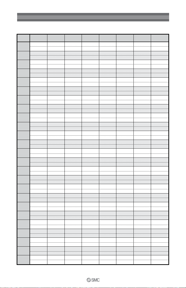
Cylinder Speed vs. Flow Chart
Cylinder Bore (inches)
In/sec
Cv Required at the cylinder Top / SCFM Lower: Cv based on 70 psi inlet and 10 psi pressure drop.
Note: This chart does not take into account the flow restrictions through the valve and tubing, etc..
1/2 3/4 1 1 1/2 2 2 1/2 3 1/4 4
.0014
1
.041
.0029
2
.081
.0043
3
.13
.0058
4
.16
.0069
5
.21
.0087
6
.25
.010
7
.28
.011
8
.33
.013
9
.36
.014
10
.36
.016
11
.44
.018
12
.49
.019
13
.53
.02 .045 .08
14
.57
.021
15
.61
.023
16
.65
.024
17
.69
.026
18
.73
.028
19
.77
.029
20
.81
.032
22
.89
.034
24
.98 2.19
.037
26
1.06
.04
28
1.14
.069
30
1.22
.0032
.091
.0065
.18
.0097
.28
.013
.37
.015
.46
.020
.56
.023
.44
.025
.73 1.3 3.0
.030
.82
.032
.91
.035
1.0
.039
1.1
.042
1.18
1.28
.048 .085
1.36
.052
1.46
.055
1.55
.058
1.65
.062 .11
1.73
.065
1.83
.072
2.01
.077
.084
2.38
.09
2.56
.097
2.74
.0058
.16
.012
.33
.17
.5
.023
.65
.028
.83
.035
1.0
.04
1.13
.045
.053
1.45
.058
1.63
.063
1.78
.07
1.8
.075
2.10
2.28
2.43
.093
2.6
.096
2.75
.103 .230
2.93
3.08
.12
3.25
.13
3.58
.14
3.90
.15
4.23
.16
4.55
.17 .39
4.88
.013
.37
.026
.74
.039
1.1
.052
1.5
.065
1.9
.078
2.2
.091
2.6
.10
.12
3.3
.13
3.7
.14
4.1
.16
4.4
.17
4.8
.18
5.2
.19
5.6
.20
5.9
.22
6.3
6.6
.25
7.0
.26
7.4
.29
8.1
.31
8.9
.34
9.6
.36
10.3
11.1
3.0
2.6
4.0
4.5
5.2
5.8
6.5
7.1
7.8
8.4
9.1
9.7
10.4
11.0
11.7
12.3
13.0
14.3
15.6
16.9
18.2
19.5
.023
.65
.046
1.3
.11
.092
.11
3.3
.14
.16
.18
.21
.23
.25
.28
.30
.32
.34
.37
.39
.41
.44
.46
.51
.55
.60
.64
.69
.036
1.0
.072
2.0
.069
2.0
.14
4.0
.18
5.0
.22
6.1
.25
7.1
.29 .49
8.1
.32
9.1
.36
10.1
.40
11.1
.43
12.1
.47
13.1
.50
14.1
.54
15.1 25.9
.58
16.2
.61
17.2 29.4
.65
18.2
.68 1.2 1.75
19.2
.72
20.2
.79
22.2
.86
24.2
.94
26.3
1.0
27.3
1.1
30.3
.061
1.73
.12
3.5
.18
5.2
.24
6.9
.3
8.6
.37
10.4
.43
12.1
13.8
.55
15.6
.61
17.3
.67
19.0
.73
20.8
.79
22.5
.85
24.2 36.4
.91
.98
27.7
1.0
1.1
31.1
32.8
1.25
34.6
1.3
38.1
1.5
41.5
1.6
45.0
1.7
48.4
1.8 2.8
51.9
.092
2.6
.18
5.2
.276
7.8
.37
10.4
.46
13.0
.55
15.6
.64
18.2
.74
20.8
.83
23.4
.92
26.0
1
28.6
1.1
31.2
1.2
33.8
1.3
1.4
39.0
1.5
41.6
1.6
44.2
1.7
46.8
49.4
1.8
52.0
2.0
57.2
2.2
62.4
2.4
67.6
2.6
72.8
78.0
5
Page 9
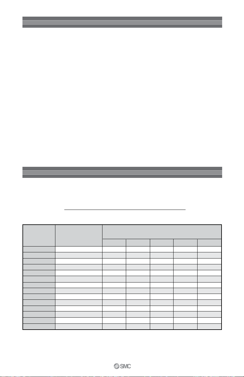
Formulas
Area (in2) = diameter2 x 0.7854 or πr
Circumference = πD = 2πr
Pressure = Force / Area
Force = Pressure • Area
Cylinder Volume (Head end) = Piston Area • Stroke
Cylinder Volume (Rod end) = (Piston Area - Rod Area) • Stroke
Compression Ratio (C.R.) = (psig + 14.7) / 14.7
Consumption (Standard ft3) = (Area in2 x Stroke in x Compression Ratio) / 1728
Air Demand (scfm) = 60 x Area in2 x Piston Speed in/s x C.R.) / 1728
Peak Air Flow (Q) = Volume / Time • C.R.
Torque = Force • Perpendicular distance from shaft
Water Weight = Pounds = US Gallons x 8.3453
π = 3.14, D = Diameter, r = Radius
2
Valve Sizing
Use the formula below with the cylinder flow chart above and the Compression Ratio and
Pressure Drop Factor chart below to calculate the required Cv for a valve.
Cv =
Piston Area (in2) x Stroke (in) x Compression Ratio
Pressure Drop Factor x Stroke Time (sec) x 29
Inlet
Pressure
10 1.7 6.5
20 2.4 7.8 11.8
30 3.0 8.9 13.6 18.0
40 3.7 9.9 15.3 20.5 23.6
50 4.4 10.8 16.7 22.6 26.4 29.0
60 5.1 11.7 18.1 24.6 29.0 32.0
70 5.8 12.5 19.3 26.5 31.3 34.8
80 6.4 13.2 20.5 28.2 33.5 37.4
90 7.1 13.9 21.6 29.8 35.5 39.9
100 7.8 14.5 22.7 31.3 37.4 42.1
110 8.5 15.2 23.7 32.8 39.3 44.3
120 9.2 15.8 24.7 34.2 41.0 46.4
130 9.8 16.4 25.6 35.5 42.7 48.4
140 10.5 16.9 26.5 36.8 44.3 50.3
Note: Pressure drop factor is based on the inlet pressure of the valve and the allowable pressure drop across the valve. For
average conditions use a 70 psi inlet pressure and a 10 psi pressure drop.
Note: For more accurate valve sizing, particularly when temperature is a factor, or the operation is speed critical, use the
following procedure.
Compression
Ratio
Pressure Drop Factors for Various
2 psi
Pressure Drops
5 psi
10 psi 15 psi 20 psi
6
Page 10
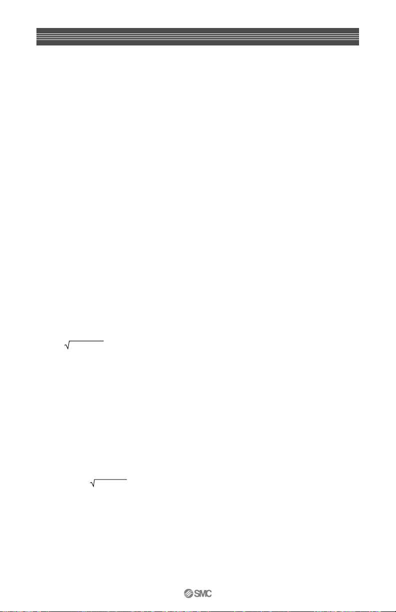
Valve Selection
Something to remember when choosing which equation to use for valve selection
1. In many instances temperature is not a
factor in system applications. In most
industrial application, compressed air
temperature is roughly the same as ambient.
If this is the case, then the use of equation
#1 is recommended. This equation has been
widely accepted to get a Cv value.
2. If temperature is a factor in the application
then equation #2 is recommended. We have
chosen to use the constant 22.48 in our
equations, but those who choose to be more
conservative may choose use 22.67 as the
constant. Both tied to ambient temperature.
3. When sizing a valve by calculating the Cv
value, determining the pressure drop across
the valve (i.e. ∆P), is an important step.
What has proven to be a good practice in
calculating Cv is the following:
(Eq. 1) Simplified equation when temperature is not a factor
1.024 x Q
Cv =
∆P x P2a
Given:
Cv = Flow coefficient
1.024 = Constant
Q = Peak Flow Rate in SCFM
∆P = Pressure drop across the valve
(See information above)
P2a = Down-stream (valve’s outlet ) pressure in PSIA
a. For general applications use 10 psi for the
pressure drop.
b. When a more conservative approach is
needed, use 5 psi for the pressure drop.
c. If cylinder and design factors are critical,
then using a 2 psi drop will more
conservatively size the valve.
4. Also remember that, for calculation
purposes, whether P1 is given in PSIG or
PSIA, P2 needs to be reflected in absolute
or PSIA (i.e. P2a)
5. Lastly, we recognize that not all applications
will have a supply pressure of a higher valve:
thus it is suggested that if P1 is 60 PSI or
less, a 5 PSI pressure drop across the valve
be used to calculate the Cv value.
(Eq. 2) Equation used when temperature is a factor in system application
Cv =
Given:
Q
(
22.48
Cv = Flow coefficient
22.48 = Constant (22.7 is often used, but 22.48 will be used on the PS exam)
TR = Temperature in Rankin (°F + 460)
Q = Peak flow retain SCFM
∆P = Pressure drop across the valve
(See information above)
P2a = Down-stream (valve’s outlet ) pressure in PSIA
)
∆P x P2a
TR
7
Page 11
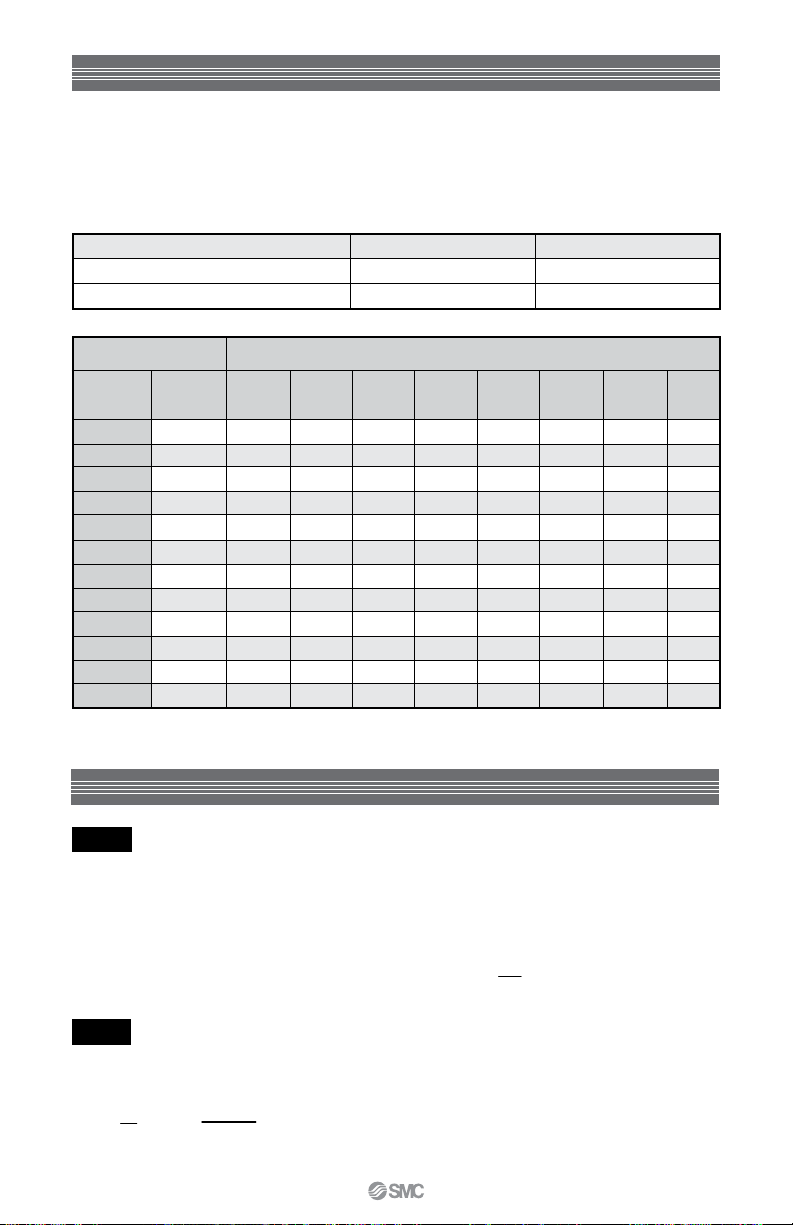
Vacuum Cup Sizing
Use the theoretical lift force (Ft) table below to determine what size vacuum cup to use for an
application. Practical lift force (Fp) should be calculated with the following formula. Use the
safety factors (t) from the table.
Fp = Ft x 1/t
PLANE OF CUP CONTACT STATIC LOAD DYNAMIC LOAD
Horizontal
Vertical
t > 4
t > 4
t > 4
t > 8
Ft (lbf)
Cup ø
(mm)
2 .031 .062 .057 .05 .049 .042 .037 .033 .029
4 .126 .245 .225 .207 .187 .170 .150 .132 .112
6 .283 .551 .509 .465 .423 .381 .340 .298 .254
8 .503 .979 .904 .829 .754 .677 .602 .527 .452
10 .785 1.53 1.41 1.29 1.18 1.06 .941 .825 .705
13 1.33 2.58 2.38 2.18 1.98 1.79 1.59 1.39 1.19
16 2.01 3.90 3.62 3.31 3.02 2.71 2.40 2.12 1.81
20 3.14 6.13 5.64 5.16 4.70 4.23 3.77 3.31 2.82
25 4.91 9.57 8.82 8.09 7.36 6.61 5.89 5.14 4.41
32 8.04 15.7 14.5 13.3 12.1 10.8 9.63 8.44 7.23
40 12.6 24.5 22.5 20.6 18.8 16.9 15.1 13.2 11.3
50 19.6 38.1 35.3 32.4 29.3 26.5 23. 6 20.6 17.7
Note: If several cups are used simply add up the forces for each cup
Area
(mm
26” 24” 22” 20” 18” 16” 14” 12”
2
)
Vacuum Pressure (InHg)
Sizing Vacuum Ejectors
Step 1 – Determine values for adsorption response time. T1 & T2
Pave = Vacuum pressure required.
Given: T2 = Adsorption response time to 95% of Pave. (Time Required by process)
Find: T1 = Adsorption response time to 63% of Pave. T1 =
Step 2 – Determine the total volume of your system by calculating component
volumes and adding them together.
2a) Tube Volume V
π
Vt =
2
x
x d
4
t: (mm
L
1000
3
)
Where:
Vt = tube volume (mm3)
d = ID of tube (mm)
L = Length of tube (m)
T2
3
8
Page 12
Sizing Vacuum Ejectors
Step 2 – Determine the total volume of your system by calculating component
volumes and adding them together. (Continued)
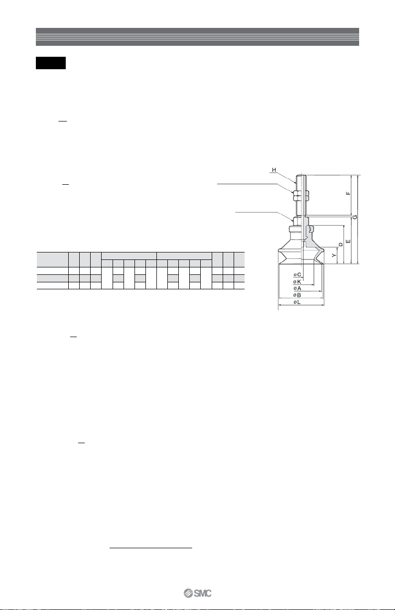
2b) Pad Volume Vp (if significant): (mm3)
Where:
V
p = pad volume (mm
d = ID of pad (mm)
L = Depth of pad (mm)
3
)
Vp =
π
2
x L
x d
4
For bellows pads
Hexagon width
across flats
π
Vpb = x A
4
Where:
2
x Y
(M6: 8, M8: 12)
Hexagon width
across flats I
Vbp = pad volume (mm3)
A = Dimension A from chart ID of Pad (mm)
Y = Dimension Y from chart Depth of Pad (mm)
Model
A B D
ZPT20B 202522
ZPT25B
32 34
23.5
27
24
29
2c) Buffer Volume V
H:
C E F C E F
3 25 8 3.5 15 12
G I G I
28.5
54.5
29
55
34
60
b (if present)
33.5
34
39
49.5
50
55ZPT32B
K L Y
121625
28
19 37
10.5
10.5
14
M6 x 1 H: M8 x 1
To approximate using C, G, & Y in the standard equation for volume:
Vp = x C
2d) Filter Volume V
x (G-Y)
4
f (if present) (mm
3
)
2
π
Consult Best Pneumatics (for example):
AMJ3000 = 30cc* 1000 = 30,000 mm3
AMJ4000/5000 = 85cc* 1000 = 85,000 mm
3
Or calculate approximate filter volume by dimensions from the catalog.
(Note that dimensions are not always given for the ID of the filter, so estimate can be used)
Vf = x d
2
π
x h
4
Where:
f = filter volume (mm
V
d = ID of filter (mm)
3
)
Y = height of filter (mm)
2e) Add component volumes together (mm
Vtotal = Vt + Vp + Vb + Vf + Vmisc
2f) Convert form mm3 to Liters
1 (Liter)
1,000,000 (mm3)
9
Vtotal (mm
3
) x = Vtotal (Liters)
3
)
Page 13
Sizing Vacuum Ejectors
Step 3 – Determine the mean vacuum flow, Q1 (liter/mm)
60
Vtotal
Q1 = x
T1
Where: Q1 = Average flow required (L/min)
V
Total = Volume of to be evacuated (liters)
Step 4 – Determine Leakage, QL (Liter/min) and Qmax (liter/min)
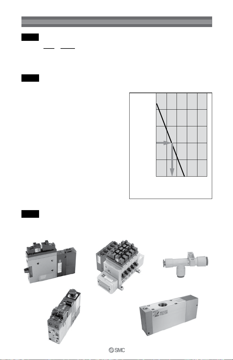
Connect pad to a test ejector and vacuum
pressure gauge. Operate ejector at recommended
supply pressure and place pad on work piece.
Note the vacuum pressure achieved and compare
it to chart from the catalog for the ejector.
If the pressure gauge shows full vacuum pressure
achieved, then there is no leakage.
Then use
Qmax = 2 x Q1
If the pressure gauge shows less than full vacuum
pressure achieved, determine QL by finding
pressure achieved on graph. Move to the right
until intersecting diagonal line above the QL flow
rate
Then use
Qmax = 3 x (Q1 + QL)
sec
1min
Flow Characteristics
–14.5 (–100)
–11.6 (–80)
–8.7 (–60)
– 5.8 (–40)
–2.9 (–20)
Vacuum pressure psi (kPa)
Vacuum flow rate scfm (L/min (ANR))
0
0
0.07
0.14
0.21
0.28
(2)
(4)
(6)
(8)
0.35
(10)
Step 5 – Choose ejector.
Choose an ejector that meets the physical characteristics, optional features
and Q max flow rate that will perform adsorption in the given time. T2
ZM
ZX
ZH
ZZM
ZL212
10
Page 14
Pipe Thread Quick Reference
Tapered pipe threads seal at the points where the crests of the threads meet the roots of the
mating threads. Standard pipe threads, NPT, PT, and BSPT require sealant to prevent the
development of a spiral leak path. NPTF threads are designed to crush the points of the
crests into the roots of the mating threads to achieve the same purpose, however, use of a
lubricant or sealant to prevent galling of the threads is preferred where not functionally
prohibited.
BSPT – British Standard Taper Pipe Threads
PT – Japanese Industrial Standard Taper Pipe Threads
{R (PT) – Taper external threads}
{Rc (PT) –Taper internal threads}
NPT – American National Standard Taper Pipe Threads
*All of the above are designed to be used with sealant to provide a pressure tight joint.
NPTF – American National Standard Dry seal Pipe Threads
*Designed to provide a pressure tight joint without the use of sealant.
PF – Japanese Industrial Standard Parallel Pipe Threads
*Straight threads use a gasket or O-ring to produce a pressure tight joint.
Basic Dimensions
PT & BSPT
Port
Threads
Size
per inch
1/16 28 .03571 .304
1/8 28 .03571 .383
1/4 19 .05262 .518
3/8 19 .05262 .656
1/2 14 .07142 .825
3/4 14 .07142 1.041
Pitch
Major
Dia.
Thread
form
angle
55 °
55 °
55 °
55 °
55 °
55 °
Threads
per inch
27 .030704 .313
27 .030704 .404
18 .05556 .540
18 .05556 .675
14 .07143 .840
14 .07143 1.050
NPT & NPTF
Pitch
Major
Dia.
Thread
form
angle
60 °
60 °
60 °
60 °
60 °
60 °
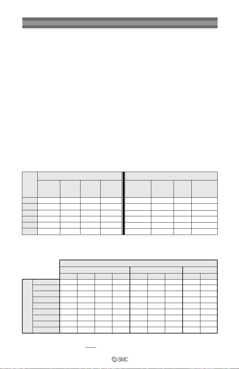
Compatibility between the above male and female is outlined below. SMC Corporation,
however, has the unique solution to all this complexity. The Uni-Fit will screw into all major
thread variations.
Female
Male
BSP
BSPT
G
NPT
NPTF
PF
PT
R
UNI
BSP
Y
Y
Y
N
N
Y
Y
Y
Y
Parallel
Rp
Y
Y
Y
N
N
Y
Y
Y
Y
PF
Taper
G
BSPT Rc PT NPT NPTF
N
Y
Y
Y
Y
Y
Y
N
N
N
N
Y
Y
Y
Y
Y
Y
Y
Y
N
Y
Y
N
N
N
N
N
N
N
N
Y
Y
Y
Y
Y
Y
American
N
Y
N
N
N
N
Y
Y
Y
N
N
N
Y
N
N
N
N
Y
Miniature threads, M5x0.8 and 10/32 UNF, will only mate as follows: 10/32 male will fit into
an M5 female, M5 male will NOT fit into a 10/32 female. Both of these threads use a
gasket to produce a pressure tight fit.
11
N
N
N
N
Y
N
N
N
Y
Page 15
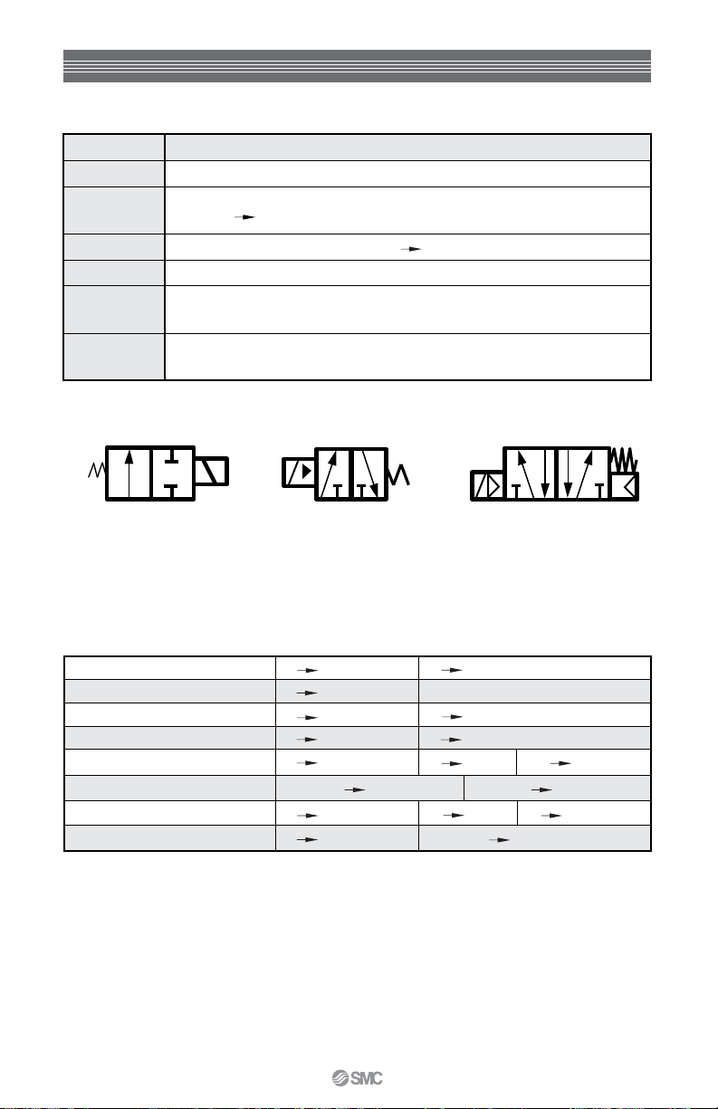
Installation Guide for Valves
“Standard ISO port call out”
Port ID
1
2
4
3 & 5
X
EX
2 Port/ 2 Position
Normally Closed
Inlet – Supply Pressure {Port P}
Output – Normally Open at rest (Unless specified in a 2 or 3 port
valve) (1 2) {Port B}
Output – Normally Closed at rest (4 5) {Port A}
Exhaust ports {Port EA & EB}
External Pilot Supply (Used to supply pilot for low pressure or vacuum
applications)
Pilot Exhaust (Never plug. Leave open or use a silencer)
A A
P
Description of Function
P EA
3 Port/ 2 Position
B
A
EA P EB
5 Port/ 2 Position
Each square represents a position or state that the valve will perform. The square that has the call
outs will always show the valve at rest.
At Rest Action
2 port NC
2 port NO
3 Port NC
3 Port NO
5 Port / 2 Position
5 Port / 3 Position – Closed
5 Port / 3 Position – Exhaust
5 Port / 3 Position – Open
P Blocked A Blocked
P A
P Blocked A E
P A E Blocked
P B A EA EB Blocked
P, B & A Blocked EA & EB Blocked
P Blocked B EB A EA
P B & A EA & EB Blocked
12
Page 16
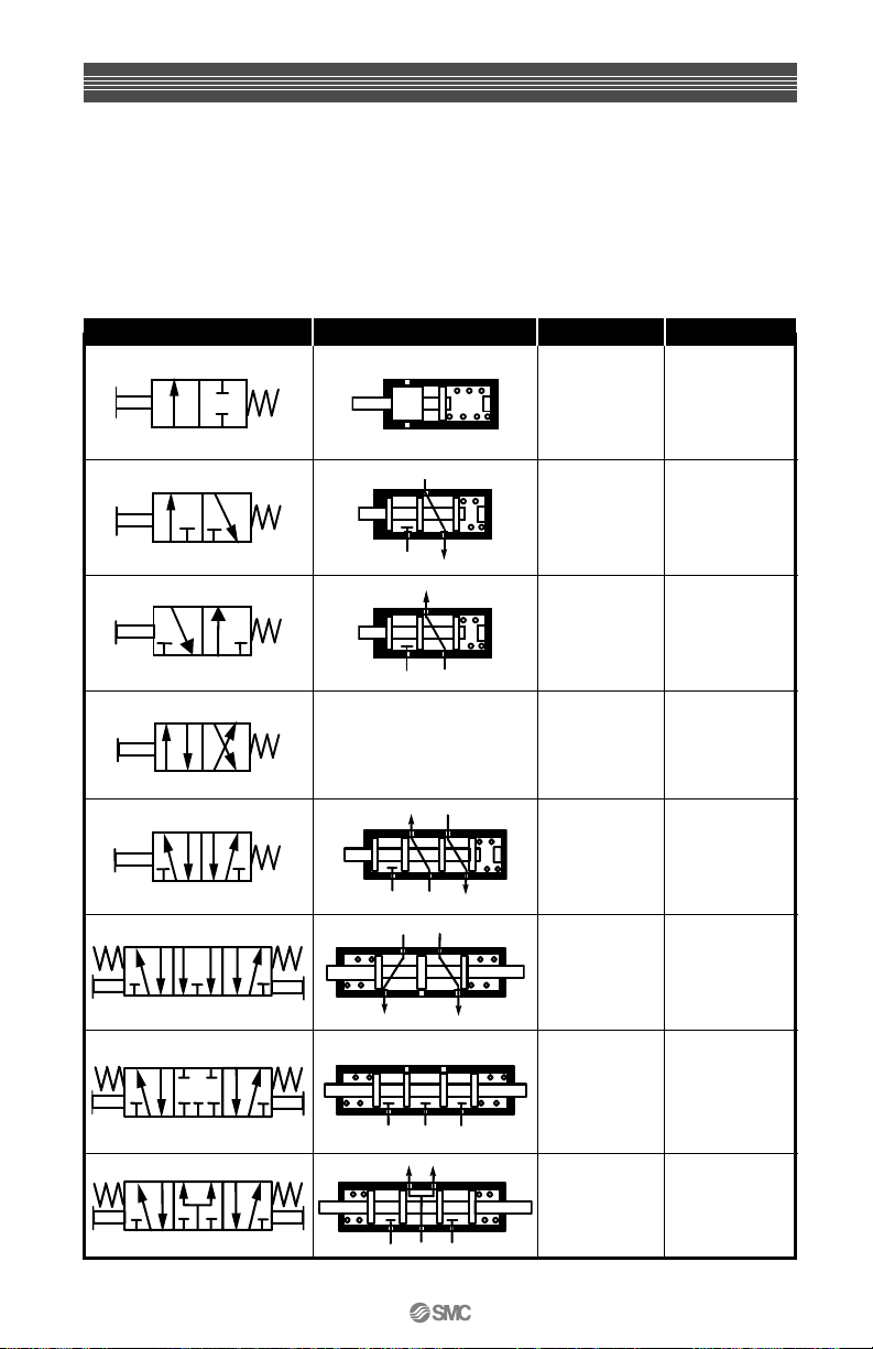
Directional Control Valves
A
Valve Functions
A directional control valve determines the flow of air between its ports by opening, closing or
changing its internal connections. The valves are described in terms of: the number of ports, the
number of switching positions, its normal (not operated) position and the method of operation.
The first two points are normally expressed in the terms 5/2, 3/2, 2/2 etc. The first figure relates to
the number of ports (excluding pilot ports) and the second to the number of positions.
The main functions and their ISO symbols are:
Symbol
Principal Construction
Function
Application
P EB EA
A
P
A
A B
P R
B A
A
P
R
R P
B A
P EB EA
A
P
R P
A
EA
A B
PEBEA
2/2 ON/OFF
without exhaust.
3/2 Normally
closed (NC),
pressurizing or
R
A
B
EB
P
exhausting the
output A
3/2 Normally
open (NO),
pressurizing or
exhausting the
output A
4/2 Switching
between output
A and B, with
common exhaust
5/2: Switching
between output
A and B, with
separate
exhausts.
5/3, Open center:
As 5/2 but with
outputs open to
exhaust in midposition
Air motors and
pneumatic tools
Single acting
cylinders (push
type), pneumatic
signals
Single acting
cylinders (pull
type), inverse
pneumatic signals
Double acting
cylinders
Double acting
cylinders
Double acting
cylinders, with the
possibility to depressurize the
cylinder
2 4
1 3 5
B A
P R1 R2
Valve Symbols, Principles, description and main applications
42
135
A
B
PR1R2
5/3 Closed
center: As 5/2
but with midposition fully
shut off
5/3 Pressurized
center:
Double acting
cylinders, with
stopping
possibility
Special applications, i.e.
Locking or
Rodless Cylinder
13
Page 17
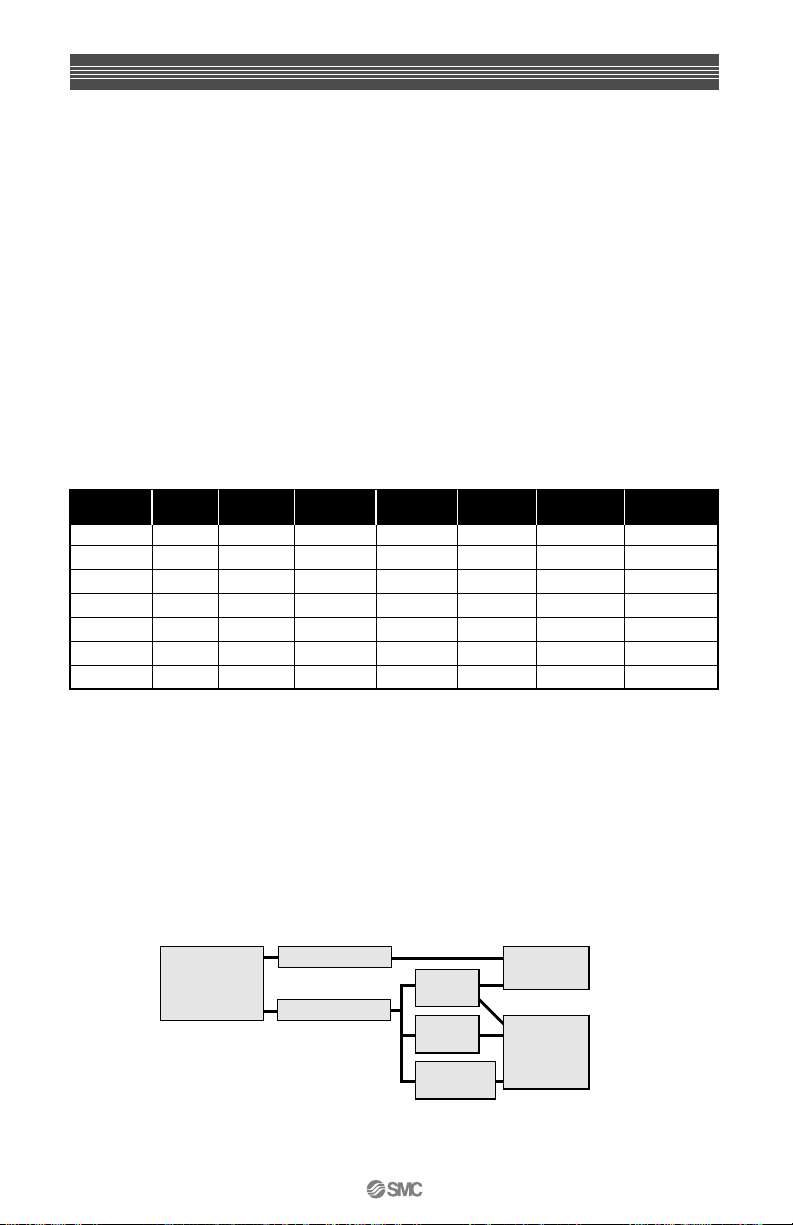
Directional Control Valves
Port Identification
The denominations or nomenclature used to identify
the various ports was not uniform until the 5/2 and 5/3
valves were invented. Until the 5/2 and 5/3 were
invented, there was more tradition than any respected
standard.
Originally, the codes previously used for older
hydraulic equipment were adopted. “P” for the supply
port comes from “pump”, the hydraulic source of fluid
energy, and is understood to mean “pressure” in
pneumatic systems.
The outlet of a 2/2 (two ports, two positions) or 3/2
valve has always been "A”, with the second, antivalent
output port labeled “B”.
The exhaust port was originally labeled “R” from
Return (to the oil tank). We can think of R as return to
atmosphere in pneumatic systems. The second
exhaust port in 5/2 valves was sometimes named S, or
Standard
Old JIS
ISO 1219
JIS
JIS
NFPA
ISO 5599
SMC
Table A Typical port identifications
Supply
Port
P
P
P
1
P
1
P (1)
NC output
A
A
A
4
A
4
A (4)
NO output
B
B
B
2
B
2
B (2)
the former “R1” and the latter “R2”.
The pilot port initiating the power connection to port A
has originally been coded “Z” (the two extreme letters
in the alphabet belongs together) and the other “Y”.
After 20 years of bargaining about pneumatic and
hydraulic symbols, one of the ISO work groups had the
idea that ports should have numbers instead of letters,
thus delaying the termination of the standard ISO 1219
by another 6 years. Supply should be “1”, the outputs
“2“ and “4”, the pilot port connecting ”1” with “2” is then
“12” etc. Table A shows the main sets of port identifications in use. Preferred are now the ISO 5599 numbers.
NC
R1
EA
R
R
5
5
Exhaust of
NO
S
S
R2
3
EB
3
EB (3)
Pilot for NC
Z
Z
Z
14
PA
14
PA (14)
Pilot for NO
Y
Y
Y
12
PB
12
PB (12)
Exhaust of
EA (5)
Monostable And Bi-stable
Spring returned valves are monostable (stable in one default or preferred condition). They have a defined
preferred position to which they automatically return. A bi-stable valve has no preferred position and remains
in either position until one of its two impulse signals are operated.
Valve Types
The two principal methods of construction are Poppet and Slide with either elastic (rubber) or metal seals.
Fig. B relates to the various combinations.
Directional
Control
Valves
Fig. B The various types of valves and sealing methods
Poppet Valves
Sliding Valves
Spool
Valves
Rotary
Valves
Plane Slide
Valves
Elastomer
Seal
Metal Seal
14
Page 18
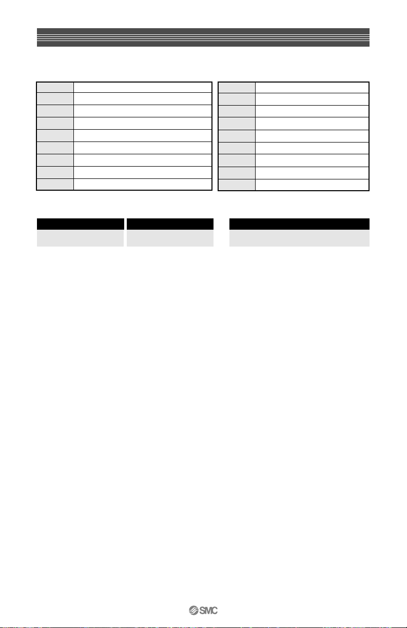
Product Data Codes
Acronyms for Materials
C3604
CR
EPR
FKM
NBR
PBT
POM
PP
Si
Copper alloy per JIS H 3250 type C 3604
Neoprene
Ethylene-propylene rubber
Fluorocarbon or Fluoro Elastomers (Viton)
Buna N or Nitrile rubber
Polybutylene terephthalate
Polyacetal (Delrin)
Poly-propylene
Silicone rubber
SL
SPC
SUS
SUS304
SUS316
SWP-B
SWRM3
TF
PFA
Indication of International Standard Code for Production Lot No.
Annual Code
Year
1996.....................A
1997.....................B
1998.....................C
1999.....................D
2000.....................E
2001.....................F
2002.....................G
2003.....................H
2004..................... I
2005..................... J
2006.....................K
2007.....................L
2008.................... M
2009.....................N
2010.....................O
2011.....................P
2012.....................Q
2013.....................R
2014.....................S
2015.....................T
2016.....................U
2017.....................V
2018.................... W
2019.....................X
2020.....................Y
2021.....................Z
2022.....................A
2023.....................B
1st digit Variable Annual Code
(Start [A] from 1996 to [Z], then return [A]
2nd digit Fixed Monthly Code
3rd & 4th digitals Fixed Country Code
(Based on ISO -3166, Common Country Code)
Variable Code
1st digit
For example:
Production in Italy on November 1996 ...AYIT
Production in USA on May 2000 ... ESI
Monthly Code
Month
January .................O
February................P
March ...................Q
April.......................R
May....................... S
June...................... T
July .......................U
August................... V
September ........... W
October ................. X
November..............Y
December..............Z
Fixed Code
2nd digit
15
Silicone rubber
Cold roll steel
Stainless steel
304 grade stainless steel
316 grade stainless steel
Piano wire
Low Carbon steel wire rod
Polytetrafluoroethylene (Teflon)
Moldable Teflon
Country Code
Company
SMC-JAPAN ..................................... Nil
SMC-USA (INDY) ................................I
SMC-CANADA ..................................CA
SMC-MEXICO.................................. MX
SMC-ARGENTINA.............................AR
SMC-CHILE.......................................CL
SMC-SWITZERLAND........................CH
SMC-GERMANY...............................DE
SMC-UK ...........................................GB
SMC-IRELAND.................................. IE
SMC-ITALY ........................................IT
SMC-FRANCE ..................................FR
SMC-SWEDEN .................................SE
SMC-AUSTRIA..................................AT
SMC-SPAIN ......................................ES
SMC-TIWAN ................................... TW
SMC-SINGAPORE ............................SG
SMC-manufacturing (SP) ................... Nil
SMC-HONG KONG........................... HK
SMC-PHILIPPINE..............................PH
SMC-MALAYSIA .............................. MY
SMC-KOREA.....................................KR
SMC-CHINA...................................... Nil
SMC-THAILAND................................TH
SMC-INDIA........................................ IN
SMC-AUSTRALIA..............................AU
SMC-NEW ZEALAND .......................NZ
Note)
1. Exception: Country code is not
available for SMC- Japan, SMC-China
and SMC Manufacturing (Singapore).
2. Exception: Country code is not
available for SMC US, instead use [ I ]
for Indianapolis factory.
3. If 2 or more production facilities will
exist in future, add number of facilities
after this code in order of registration.
4. In case of necessity of additional
information, Job No. etc., add them
after this code.
Fixed Code
3rd & 4th digits
Page 19

Cylinder Part Number Building Information
• Style? _______________________
• Bore? _______________________
• Stroke? ______________________
• Single or Double Acting?
• Spring return or spring extend?
Mounting? ____________________
Inch or Metric?
Auto - Switch Capable? Y or N
• Number of Switches? ____________________
• Reed or Solid State? NPN or PNP?
• What Voltage? ____________________
• Standard or Long Leads?
• Prewired lead connector?
Options
• Oversize rod?
• Cushions? Air or Urethane?
• Non–rotating rod?
• Rod boot? Nylon or Neoprene?
• Low or High Temp application?
• Low Friction?
• Stainless Steel Rod?
• Adjustable Stroke? Extend or Retract?
• Dual Stroke? Single or Double Rod?
• Extended rod? Inch or Metric?
• Extended rod threads? Inch or Metric?
• Special Rod threads?
Accessories
• Rod Eye • Single Rod Clevis
• Double Rod Clevis • Foot Bracket
• Flange (Head or Rear) • Trunnion
Speed Load Mounting Direction
Temperature Environment
Moments: X Y Z
Note: Use cylinder dimensional sketch on page 19, if necessary.
16
Page 20
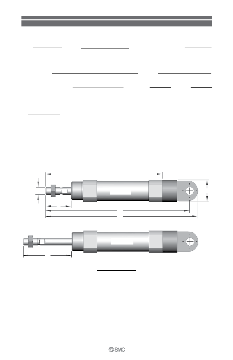
Crossing Over a Cylinder
Bore Stroke Inch or Metric Port Size
Thread Size Mounting Style
Line Pressure Load
Vertical or Horizontal Lift Switches Style
Dimensions:
A B C D
E F G
A
17
B
C
G
Retracted
E
D
Extended
Stroke = G–C
F
Page 21

Valve Part Number Building Information
• How Many Ports? _________________
• How Many Positions? _________________
• Flow? _________________
• Rubber or Metal Seal? _________________
• What is the application? _________________
Cylinder bore? _____________ Stroke? ______ ______
Speed? ____________ Blow off? _____________
• Single or Double Solenoid? _________________
• Voltage? _________________
• Style of Connector? _________________
Plug-In, DIN or Grommet?
Serial or Discrete?
• Body Ported, Sub-plate or Manifold?
• Foot bracket, Mounting holes or DIN Rail?
• Port Size? _________________ Threaded or One Touch Fitting
• How Many Stations? _________________
• Operating Pressure? _________________
• Temperature? _______________________
• Environment? ________________________
18
Page 22

Vacuum Order Sheet
• Ejector - Single stage, 2-stage or 3-stage nozzle?
• Port size? ______________
• Flow? ______________
• Application:
• Horizontal or Vertical Lift?
• Load Material? ______________
• Weight of Load? ______________
• Number of Pads? ______________
• Surface Material? _____________
• Pad Diameter? ______________
• Flat, Flat w/ Ribs, Deep or Bellows?
• Material? ______________
• Connection – Vertical or Horizontal Vacuum entry?
• Buffer or Non – Buffer?
• Female Fitting, Barb or One-Touch?
• Vacuum Pressure? ______________
• Vacuum Filter? ______________
• Solenoid Valves for Supply and/or Blow off?
• Voltage? ______________
• Type of connector, Grommet, L type, M type?
• Individual or Manifold?
• Vacuum Switch or Adsorption Conformation?
PNP or NPN?
19
Page 23
Auto Switches
REED SWITCHES: A thin metal contact is drawn closed by the magnetic field of the
piston magnet. Since this is a mechanical switch it will wear out over time and is
susceptible to vibration and shock. Their advantage is that they are inexpensive and
can be used with AC voltages.
SOLID– STATE SWITCHES: The magnetic field generated by the piston magnet
causes a current flow inside the switch. Since there are no moving parts, the switch life
is much longer than a reed switch and they are less prone to vibration and shock. They
are more expensive, can only be used with DC voltages and you need to know whether
you need a sinking or sourcing switch.
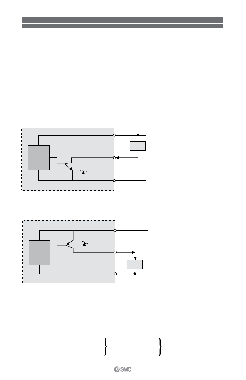
Current Sinking (NPN) –The switch sensor “sinks” current from the load through the sensor to
ground. The load is connected between the positive voltage supply and the output lead of the sensor.
3-Wire NPN Sensor Connection
Brown (Red) + V
Sensor
Main
Circuit
Current Sourcing (PNP) – The switch sensor “Sources” current through load to ground. The load is
connected between the output lead of the sensor and the negative “ground” lead of the supply.
Load
Output
Black (White)
Blue (Black) 0V
3-Wire PNP Sensor Connection
Brown (Red) + V
Sensor
Main
Circuit
Three wire DC sensors include one wire that provides voltage to the sensor, an output signal wire
and a ground wire. Most electro–mechanical loads (relays, counters, solenoids etc.) can use
either a sink or source type switch provided it is wired properly. The proper sensor type must be
chosen when used with solid-state load and programmable controllers due to the fact that some
of these loads must be grounded.
Wire Colors: SMC has changed the wire colors on all of our switch products. This was
done to conform to European standards that are being adopted worldwide.
Positive
Negative
Output
Red
Black (old colors)
White
Output
Black (White)
Load
Blue (Black) 0V
Brown
Blue (new colors)
Black
20
Page 24
Pressure Switches and Their Simplified Operation
Output deviation factor %F.S.
Supply Voltage
Pressure
Switch
+
12
to
–
24VDC
PNP Switch
Load
Pressure
Switch
Main circuit
Brown DC (+)
Black OUT
Load
Blue DC (–)
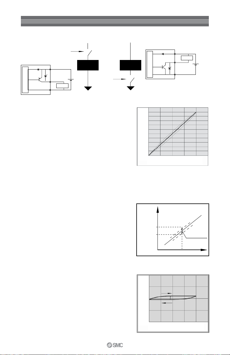
Sourcing – PNP is often referred to as Sourcing, because
the switch closes and provides the source voltage to the load
Sinking – NPN is often referred to as Sinking, because the
switch closes and sinks the current to ground
Normally Open – Does not pass the signal until the set point
is reached
Normally Closed – Passes current until the set point is
reached
FS or Full Scale – The maximum setting minus the
minimum setting.
Ex. ITV1050 0.9MPa – 0.005MPa = 0.895 MPa Full Scale
(130.5 psi – 0.725 psi = 129.775 psi)
Linearity – The nearness with which the plot of a signal, or
variable, plotted against a prescribed linear scale approximates a straight line. Output error to reference value
Repeatability – The ability of the instrument to provide the
same output every time for the same input. Usually given as
a % of the FS value
Sensitivity – Often described as the minimum change of
input to which the system is capable of responding. Usually
expressed in % of Full Scale
Hysteresis – The difference in output when the measured
value is first approached with increasing and then decreasing
values. Expressed in % of Full Scale
Impedance – Resistance of a load that hinders the flow.
Current Consumption – The amount of current needed for
normal operation, does not include load current.
Watts (W) and Volt Amps (VA) – Both of these units are
used to express electrical power.
Watts is for DC voltage and Volt Amps is for AC voltage.
If you have any questions on basic electronics there is an
entry in the Product Application Database that explains basic
electronics.
21
Supply Voltage
Load
NPN Switch
(0.10 MPa = 14.5 psi)
This graph shows the repeatability of an analog
output, pressure display and a switch (ON-OFF)
output’s moving point. The pressure is increased or
decreased under normal temperature (77°F (25°C)).
Brown DC (+)
Black OUT
Main circuit
0.10
0.09
0.08
0.07
0.06
0.05
0.04
0.03
0.02
Set pressure MPa
0.01
0.00
0 25 50 75 100
Blue DC (–)
Input signal %F.S.
Linearity
Analog output
Pressure display
Switch output
Repeatability
1.0
0.5
0.0
-0.5
-1.0
Out
Return
0 25 50 75 100
Input signal %F.S.
Hysteresis
Load
+
–
Output moving point
12
to
24VDC
Page 25
NEMA Ratings (Electrical Enclosures)
An enclosure is a surrounding case constructed to provide a degree of protection to personnel
against accidental contact with the enclosed equipment and to provide a degree of protection to
the enclosed equipment against specified environmental conditions. These are the more
common classifications as they pertain to pneumatic components such as valves.
NEMA 1 Intended for Indoor use primarily to provide a degree of protection against contact
with enclosed equipment.
NEMA 2 Intended for indoor use primarily to provide a degree of protection against limited
amounts of falling water and dirt.
NEMA 3 Intended for outdoor use to provide a degree of protection against windblown dust,
rain, sleet and external ice formation.
NEMA 3R Intended for outdoor use to provide a degree of protection against falling rain, sleet
and external ice formation.
NEMA 3S Intended for outdoor use to provide a degree of protection against windblown dust,
rain, sleet and provide for operation of external mechanisms when ice laden.
NEMA 4 Intended for indoor and outdoor use primarily to provide a degree of protection against
windblown dust and rain, splashing water and hose directed water.
NEMA 4X Intended for indoor and outdoor use primarily to provide a degree of protection against
corrosion, windblown dust and rain, splashing water and hose directed water.
NEMA 6 Intended for indoor or outdoor use primarily to provide a degree of protection against
entry of water during occasional submersion to a limited depth.
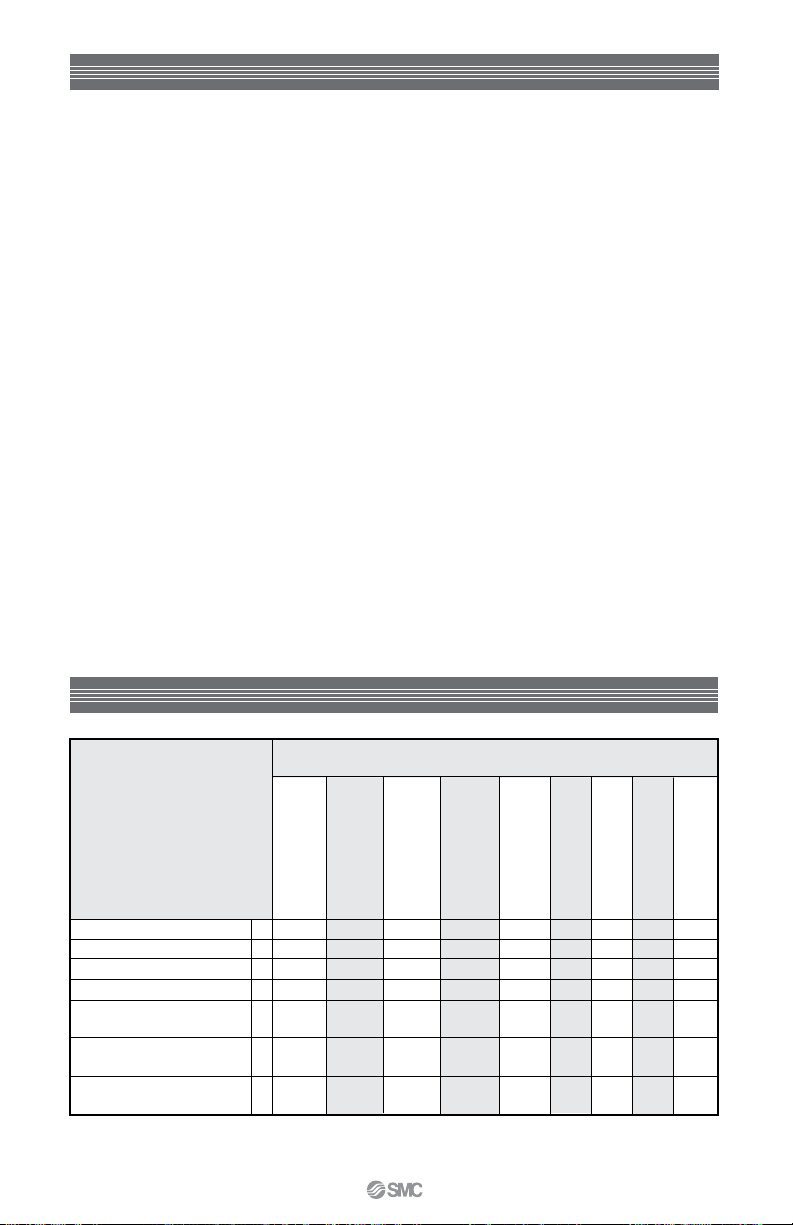
IP Ratings (Electrical Enclosures)
2ndNumeral:
st
Numeral:
1
Degree of protection with
respect to persons and
solid objects
Not protected 0 IP00 IP01 IP02
Solid objects > ø50mm
Solid objects > ø12mm
Solid objects > ø2.5mm
Solid objects > ø1.0mm
Dust protected 5 IP54 IP55IP
Dust tight 6 IP65IP66IP67IP
Note: find IP rating and follow across and up to find degree of combined protection. IP65 and NEMA 4 are
roughly equivalent
Degree of protection with respect to harmful ingress of water
Non protected
Dripping water
Dripping water
+/- 15 °
Spraying water
+/- 60 °
Splashing water
360 °
Water jets
1 IP10 IP11 IP12 IP13
2 IP20 IP21 IP22 IP23
3 IP30 IP31 IP32 IP33 IP34
4 IP40 IP41 IP42 IP43 IP44 IP45IP
Heavy seas
46
56
Immersion
Submersion
68
22
Page 26
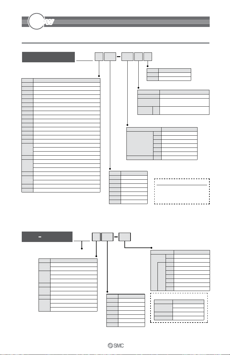
New
New
Threaded Type
Symbol
Male connector
H
Hexagon socket head male connector
S
Female union
F
Male elbow
L
45° male elbow
K
Universal male elbow
V
Hexagon socket head universal male elbow
VS
Universal female elbow
VF
Female elbow
LF
Double universal male elbow
VD
Triple universal male elbow
VT
Branch universal male elbow
Z
Double branch universal male elbow
ZD
Triple branch universal male elbow
ZT
Extended male elbow
W
Male branch tee
Union Tee
T
Different diameter Tee
Male run tee
Y
Branch “Y”
Union “Y”
U
Different diameter Union “Y”
Different diameter plug-in “Y”
X
Bulkhead union
E
Bulkhead connector
Bulkhead union elbow
LE
Adaptor
N
Model
How to Order
A S05 34KQ2 H
Model
∗ /A, N
Port size/Applicable tubing O.D.
Thread
connection
Tubing connection
∗ Only for “Bulkhead union” and “Bulkhead union elbow”.
Applicable tubing O.D.
Symbol
01
03
05
07
09
11
13
Size
ø1/8"
ø5/32"
ø3/16"
ø1/4"
ø5/16"
ø3/8"
ø1/2"
One-Touch Fittings
Series KQ2
Male thread seal method
Symbol
Thread material/Surface treatment
Symbol
A
N
Bulkhead
union
Symbol
Seal method
Nil
S
None
With thread sealant
Thread material/Surface treatment
Brass (compatible with KQE)
Brass + Electroless nickel plated
Compatible to KQE-X2
J
Interchangeable with KJE
32
33
34
35
36
37
∗
00
Size
10-32UNF
NPT1/16
NPT1/8
NPT1/4
NPT3/8
NPT1/2
Same diameter tubing
Spare Parts
Use the part number below to
order the gasket for sealing
10-32UNF thread.
Gasket for 10-32UNF: M-10/32G
Tube Tube Type
Symbol
H
L
R
T
TW
U
23
One-touch fittings
Model
Straight
Different diameter straight
Elbow
Plug-in elbow
Reducer elbow
Plug-in reducer
Union tee
Different diameter tee
Cross union
Union “Y”
Plug-in “Y”
Different diameter union “Y”
Model
A05 00KQ2 H
Applicable tubing O.D.
Symbol
01
03
05
07
09
11
13
Size
ø1/8"
ø5/32"
ø3/16"
ø1/4"
ø5/16"
ø3/8"
ø1/2"
Port size/Applicable tubing O.D.
Symbol
00
99
01
03
05
07
09
(Reducer)
11
Tubing (Rod) connection
Different dia. Tubing
13
Size
Same diameter tubing
Same diameter rod
ø1/8"
ø5/32"
ø3/16"
ø1/4"
ø5/16"
ø3/8"
ø1/2"
Accessory
Symbol
KQ2N
KQ2C
KQ2P
Name
Nipple
Reducer nipple
Tube cap
Plug
Page 27
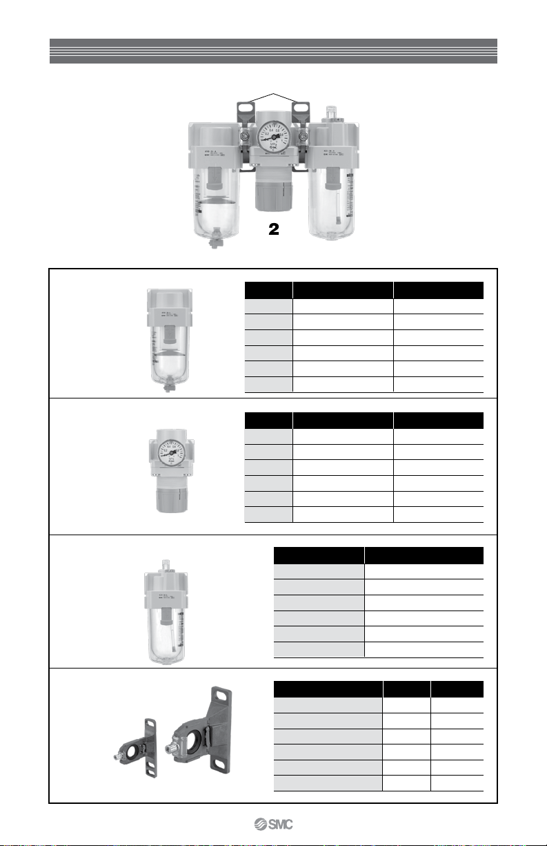
FRL Cheat Sheet
4
2
1. Filter
2. Regulator
3. Lubricator
1
Port Size
1/8” NPT
1/4” NPT
3/8” NPT
1/2” NPT
3/4” NPT
1” NPT
Port Size
1/8” NPT
1/4” NPT
3/8” NPT
1/2” NPT
3/4” NPT
1” NPT
3
Part No. W/ Manual Drain
AF20-N01-CZ-A
AF20-N02-CZ-A
AF30-N03-Z-A
AF40-N04-Z-A
AF50-N06-Z
AF60-N10-Z
Part Number W/O gauge
AR20-N01H-Z-A
AR20-N02H-Z-A
AR30-N03H-Z-A
AR40-N04H-Z-A
AR50-N06H-Z
AR60-N10H-Z
Port Size
1/8” NPT
1/4” NPT
3/8” NPT
1/2” NPT
3/4” NPT
1” NPT
Part No. W/Auto Drain
AF20-N01C-CZ-A
AF20-N02C-CZ-A
AF30-N03D-Z-A
AF40-N04D-Z-A
AF50-N06D-Z
AF60-N10D-Z
Part Number W/gauge
AR20-N01GH-Z-A
AR20-N02GH-Z-A
AR30-N03GH-Z-A
AR40-N04GH-Z-A
AR50-N06GH-Z
AR60-N10GH-Z
Part Number
AL20-N01-3CZ-A
AL20-N02-3CZ-A
AL30-N03-3Z-A
AL40-N04-3Z-A
AL50-N06-3Z
AL60-N10-3Z
4. Brackets
Air Prep Unit Port Size
1/8” NPT (AC20 Series)
1/4” NPT (AC20 Series)
3/8” NPT (AC30 Series)
1/2” NPT (AC40 Series)
3/4” NPT (AC50 Series)
1” NPT (AC60 Series)
Spacer
Y200-A
Y200-A
Y300-A
Y400-A
Y500-A
Y600
Spacer-T
Y200T-A
Y200T-A
Y300T-A
Y400T-A
Y500T-A
Y600T
24
 Loading...