

Page 1

10/100Base-TX to 100Base-FX
Media Converter
Media Converter
Medienkonverter
Convertisseur de média
V2.0
0100-03807-3203
Quick Start Guide
Installationskurzanleitung
Guide d'installation
SMC-FXSC
Page 2
English 2 - 5
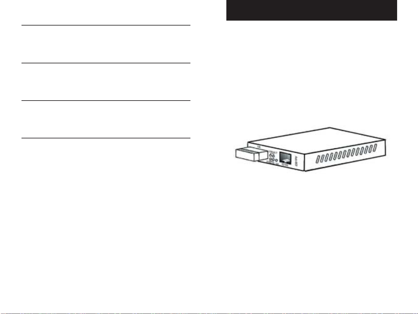
Media Converter
Package Contents
The following items should be included in the package:
English
German 6 - 9
French 10 -13
Copyright & Notes 14
•One media converter unit
•One AC adapter
• Self-adhesive pads (4 pieces)
•User’s Manual CD-ROM
•Warranty Card
(unit with SC connector shown below)
English
NOTE: Please visit us at www.smc-europe.com to register your
product and become eligible for various support services and
product information up-date!
1 2
Page 3
Features
• Complies with IEEE 802.3, IEEE 802.3u and 10/100BASE-TX
standards
• RJ-45 port auto-MDI detection and setting
• DIP switch enabled half/full-duplex mode
• Status LEDs for quick and easy network monitoring
• Extended distances up to 2km (6,600 ft) for multi-mode fiber
• External power supply
• FCC Class A & CE approved
Setting Up
1. Installation
There are two options:
• Wall-mount - Insert two screws into the wall-mount hole fixtures
• Desktop - Affix the 4 self-adhesive pads as indicated.
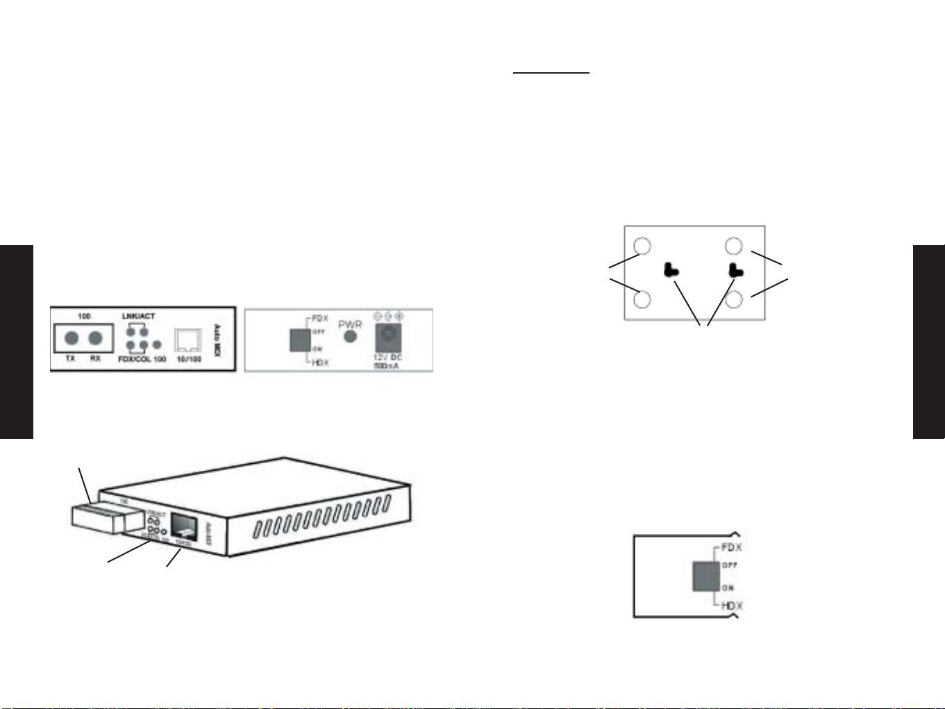
Under Panel View of Unit Housing
General Guide
English
Front Panel View
10/100BASE-TX to 100BASE-FX Media Converter
Fiber optic port
Status LED
indicators
UTP port
(RJ-45)
Rear Panel View
Self-adhesive
pads
Holes for wall-mounting
2. Setting Half/Full-duplex
Toggle the DIP switch (located on the rear panel) to set unit to full-
duplex or half-duplex mode as necessary.
• FDX - Enables full-duplex mode
• HDX - Enables half-duplex mode
NOTE: It is possible to change between duplex modes without
disconnecting power or cables.
View of DIP Switch on Rear Panel
Self-adhesive
pads
English
3 4
Page 4

Medienkonverter
3.Powering On
Connect the power adapter to the power jack (located on the
rear panel). Plug the adapter into power source. The green PWR
LED will light to indicate normal power status
AC Power jack
4. Connecting & LED Guide
LED Status Interpretation
English
LNK On Link established
ACT Flashing Data Traffic
FDX On Full-duplex mode enabled
COL Flashing Collision occured
100 On Unit in 100BASE-TX mode
Packungsinhalt
Prüfen Sie, ob folgende Artikel enthalten sind:
•1 Medienkonverter
•1 Netzteil
•4 Selbstklebende Auflagepuffer
• CD-ROM mit Benutzerhandbuch
• Garantiek arte
(Einheit unten mit SC-Anschluss abgebildet)
Deutsch
HINWEIS: Bitte besuchen Sie uns unter www.smc-europe.com bzw.
www.smc.de, um Ihr Produkt zu registrieren. Damit stehen Ihnen
umfassende Supportleistungen, wie u.a. Support, Handbücher und
Updates, zur Verfügung.
Fiber optic (SC interface)
5 6
UTP (RJ-45 interface)
Page 5

Merkmale und Funktionen
Einrichtung
• Erfüllt die Standards IEEE 802.3, IEEE 802.3u und 10/100BaseTX
• RJ-45-Anschluss mit automatischer MDI-Erkennung und Einstellung
• Über DIP-Schalter aktivierter Halb-/Vollduplexmodus
• Status-LEDs für schnelle und einfache Netzwerküberwachung
• Erweiterte Distanzen von bis zu 2 km für Multimode-Faser
• Externe Stromversorgung
• FCC Klasse A & CE-zertifiziert
Allgemeiner Überblick
Deutsch
Ansicht von vorn
Medienkonverter 10/100Base-TX auf 100Base-FX
Glasfaseranschluss
Ansicht von hinten
1. Montage
Es gibt zwei Möglichkeiten:
• Wandmontage – Setzen Sie zwei Schrauben in die für die
Wandmont a ge vorgesehenen Löcher ein.
• Tischaufstellung – Bringen Sie die vier Auflagepuffer wie
abgebildet an.
Ansicht des Gehäuses von unten
Selbstklebende
Auflagepuffer
Löcher zur Wandmontage
2.Halb-/Vollduplex einstellen
Stellen Sie mit dem DIP-Schalter (auf der Geräterückseite) nach
Bedarf Voll- oder Halbduplexbetrieb ein.
• FDX - Vollduplexmodus
• HDX - Halbduplexmodus
Selbstklebende
Auflagepuffer
Deutsch
HINWEIS: Der Duplexmodus kann ohne Ausschalten oder Ausstecken
des Geräts geändert werden.
Status-LEDs
7 8
Anschluss
(RJ-45)
Ansicht des DIP-Schalters auf der Geräterückseite
Page 6

Convertisseur de média
3.Einschalten
Schließen Sie das Netzkabel an den Netzanschluss (auf der
Rückseite) an. Schließen Sie das Netzteil an eine Netzsteckdose an.
Die grüne Stromversorgungs-LED (PWR) beginnt zu leuchten, was
den normalen Betriebszustand darstellt.
Netzanschluss
4. Verbinden und LEDs
Deutsch
LED Zustand Bedeutung
LNK Ein Verbindung ist aktiv
ACT Blinkt Datenverkehr
FDX Ein Vollduplexmodus aktiviert
COL Blinkt Kollision
100 Ein 100Base-TX-Modus
Contenu de l’emballage
L’emballage doit contenir les éléments suivants :
•1 convertisseur de média
•1 transformateur CA
•4 patins adhésifs
• CD-ROM contenant le Manuel d’installation
• Carte de garantie
(voir la figure ci-dessous montrant un convertisseur équipé d’un
connecteur SC)
Français
REMARQUE : Rendez-vous sur le site www.smc-europe.com/fr pour
enregistrer votre produit. Vous pourrez ainsi bénéficier d’un ensemble
de services d’assistance et recevoir des informations sur les mises à
jour des produits.
Glasfaser (SC-Schnittstelle)
9 10
UTP (RJ-45-Schnittstelle)
Page 7

CARACTÉRISTIQUES
MISE EN SERVICE
• Conforme aux normes IEEE 802.3, IEEE 802.3u et 10/100BaseTX
•Auto MDI/MDI-x
• Commutateur DIP pour les modes Half Duplex et Full Duplex
• Témoins d’état pour un contrôle instantané et aisé du réseau
• Fonctionnement jusqu’à une distance de 2km pour une fibre en
multimod e
• Alimentation externe
• Conforme aux normes FCC Classe A et CE
PRÉSENTATION GÉNÉRALE
Français
Vue de la façade avant
Convertisseur de média 10/100BASE-TX vers 100BASE-FX
Port à fibre optique
Vue de la façade arrière
1. Installation
Il existe deux types d’installation :
• Fixation murale – Fixez le convertisseur à l’aide de deux vis.
• Fixation à plat – Collez les quatre patins adhésifs comme indiqué
dans la figure ci-dessous.
Vue arrière du boîtier de fixation de l’unité
Patins
adhésifs
Orifices pour fixation murale
2. Activation des modes Half/Full Duplex
Basculez le commutateur DIP (situé sur la façade arrière) sur le
mode Full Duplex ou Half Duplex, selon votre convenance.
• FDX – Active le mode Full Duplex.
• HDX – Active le mode Half Duplex.
REMARQUE : Vous pouvez changer de mode sans déconnecter ou
mettre hors tension l’unité.
Patins
adhésifs
Français
Témoins d’état
11 12
Port UTP
(RJ-45)
Vue du commutateur DIP sur la façade arrière
Page 8

3.Mise en marche
Branchez le câble du transformateur sur la prise d’alimentation CA
(située sur la façade arrière). Branchez le transformateur sur une
source d’alimentation. Le témoin lumineux PWR vert s’allume pour
indiquer que l’appareil est sous tension.
Prise CA
4. Fonctions des témoins et liaisons
Témoin État Signification
Français
LNK Allumé Liaison active
ACT Clignotant Transmission de données
FDX Allumé Mode Full Duplex activé
COL Clignotant Une collision s’est produite
100 Allumé L’unité fonctionne en mode 100BASE-TX
Warranty
Complete warranty information for all SMC products is available on
the SMC web site at www.smc-europe.com and in the English
manual on the CD-Rom.
Full Installation Manual
Full installation manual in English is provided on the
Installation CD-Rom.
Copyright
Copyright
Information furnished by SMC Networks, Inc. (SMC) is believed to
be accurate and reliable.
However, no responsibility is assumed by SMC for its use, nor for
any infringements of patents or other rights of third parties
which may result from its use. No license is granted by
implication or otherwise under any patent or patent rights of
SMC. SMC reserves the right to change specifications at any time
without notice.
Trademarks:
SMC is a registered trademark and EZ Connect is a trademark of
SMC Networks, Inc. Other product and company names are
trademarks or registered trademarks of their respective holders.
Fibre optique (interface SC)
13 14
UTP (interface RJ-45)
 Loading...