

Page 1

EZ Switch 10/100
SMC-1026DT V.2
Unmanaged Ethernet/Fast Ethernet Switch
User Guide
for
Expansion Module Series
SMC-EZ1026FMSC V.2
SMC-EZ1026GSSC V.2
SMC-EZ1026LXSC V.2
SMC-EZ1026GT V.2
Page 2

Introduction
The Expansion Module series for SMC-EZ-1026DT V.2 switch can be
installed into a number of 24+1/2 intelligent switch devices to provide 100
Mbps Fiber and 1000 Mbps UTP/Fiber connections to other compatible
network devices.
The Expansion Modules are designed to extend the distance between
the Switch and other devices or as backbone in the networking
infrastructure.
The Maximum distance connected by optical fiber is up to 2 Km
(multi-mode fiber) or 60 Km (single-mode fiber). You can regard this fiber
port as backbone in the networking infrastructure. There are four types of
fiber port connectors available for 100 Base-FX expansion modules, which
include SC/SC single-mode/MT-RJ/VF-45 connectors. For Gigabit fiber
expansion modules, there are two types of fiber port connector available,
which include 1000 Base-SX and 1000 Base-LX connectors.
Here is the list of the Expansion Modules:
1. Gigabit-SX Module (SMC-EZ1026GSSC V.2)—1000 Mbps operation
over multi-mode fiber optic cable
2. Gigabit-LX Module(SMC-EZ1026GLSC V.2)—1000 Mbps operation
over either single-mode or multi-mode fiber optic cable
3. 1000-T Module (SMC-EZ1026GT V.2)—1000 or 100/10 Mbps operation
over Category 5 or better unshielded twisted-pair (UTP) or shielded
twisted-pair (STP) cables
4. 100-FX SC Single-mode Module (SMC-EZ1026FMSC V.2)—100 Mbps
operation over single-mode fiber optic cable
Page 3

Expansion Module Series ---
SMC-EZ1026GT V.2: Gigabit 1000 Base-T Module
Figure 1. 1000 Base-T N-Way Module Front View
Features:
One 10/100/1000 Mbps N-Way auto-negotiation RJ-45 port
Automatic MDI/MDIX supported
Pause-Frame Base flow control on Full-duplex mode
Full-duplex modes supported
LED-indicators for 1000M, 100M, LK/ACT, FDX status
LED Indicators
There are four types of LED indicators for the RJ-45 Port. If there is no
connection to this port, the corresponding LED indicators are not lit.
1000M The LED indicator is green when the port is connected to a
1000Mbps devices. This LED indicator is not lit when the port is
connected to a 10/100Mbps device.
LK/ACT The LED indicator is green when there is a connection
FDX The LED indicator is yellow when the port is operating in
The LED indicator is
100M
100Mbps devices. This LED indicator is not lit when the port is
connected to a 10/1000Mbps device.
secured to a device ( Link ) to the port . This LED indicator blinks when
there is a data transmission ( Activity ) taking place at the port.
Full-duplex mode. When the port is operating in Half-duplex mode, the
LED indicator is not lit. When collisions are occurring at the port, the
LED indicator blinks.
green
when the port is connected to a
Page 4
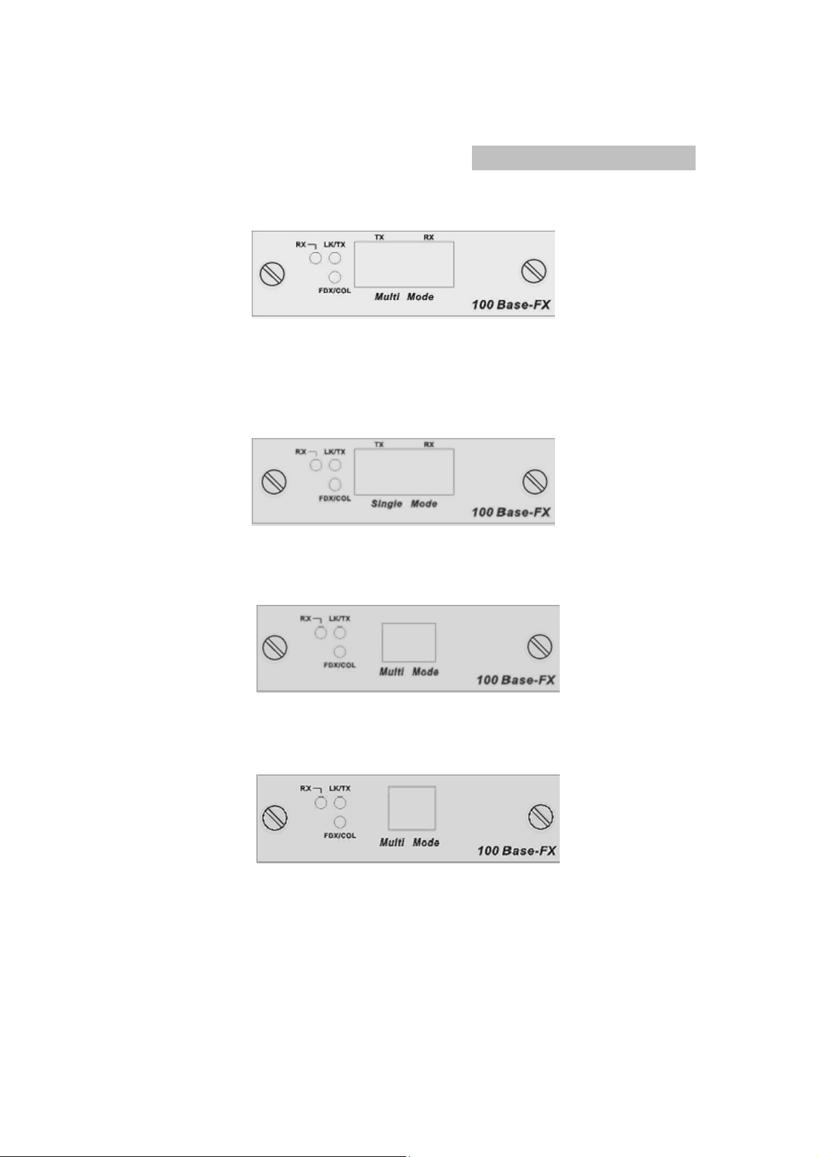
100Base-FX Fiber Module Series
1. 100Base-FX( SC ) Fiber Module
Figure 2. 100Base-FX ( SC ) Module Front View
2. 100Base-FX( SC Single-mode ) Fiber Module
SMC-EZ1026FMSC V.2
Figure 3. 100Base-FX ( SC Single-mode ) Module Front View
3. 100Base-FX( MTRJ ) Fiber Module
Figure 4. 100Base-FX (MT-RJ) Module Front View
4. 100Base-FX( VF-45 ) Fiber Module
Figure 5.
Features:
One 100Mbps fiber ports (SC/SC single-mode/MTRJ/VF-45 connectors)
Full-duplex modes supported
100Base-FX (VF-45) Module Front View
Page 5

LED-indicators for LK/TX, RX, FDX/COL statuses
For establishing fiber links cable distance up to 2 Km (multi-mode) or 60
Km (single-mode)
LED Indicators
There are three LED indicators for the Fiber connection port. If there is no
connection to this port, the LED indicators will not lit.
LK/TX The LED indicator is green when there is a connection secured
to a device ( Link ) to this port . This LED indicator blinks when there is a
data transmission taking place at this port.
RX The LED indicator blinks when there is a data receiving taking
place at this port.
FDX/COL The LED indicator is yellow when the port is operating in
Full-duplex mode. When the port is operating in Half-duplex mode, the
LED indicator is not lit. When collisions are occurring at the port, the
LED indicator blinks.
SMC-EZ1026GLSC V.2 :Gigabit 1000Base-LX/SC Fiber
Modules
SMC-EZ1026GSSC V.2: Gigabit 1000Base-SX/SC
Fiber Modules
Figure 6. Gigabit 1000Base-SX Module Front View
Figure 7. Gigabit 1000Base-LX Module Front View
Page 6

Features
One 1000Mbps fiber port ( SX/LX connectors )
Full-duplex modes supported
LED-indicators for LK, ACT statuses
For establishing fiber links cable distance up to 500 m ( 1000Base-SX
SC multi-mode), 10 Km ( 1000Base-LX SC single mode).
LED Indicators
The are two LED indicators for the Gigabit Fiber connection port. If there is
no connection to this port, the LED indicators are not lit.
LK The LED indicator is green when there is a connection securely to
a device ( Link ) to the corresponding port.
ACT This LED indicator blinks green when there is a data transmission
( Activity ) taking place at the corresponding port.
Installation Steps
To install the Expansion Modules, follow these steps:
1. First of all, power off the switch, which you want to insert the module.
2. Insert the module into a SMC-EZ1026DT V.2 Switch module slot
and secure the retaining screws.
3. After the modules are installed, reset or reboot switch.
4. Connect the network cable to the module port and check the module
and network device for correct operation.
Details on these steps are provided in the following document.
Insert the Module Into the Slot
The modules are installed into SMC-EZ1026DT V.2 expansion slots
intelligent switch as follow:
1. Unscrew the thumbscrews on the blank bracket. Remove the blank
bracket and set aside, but do not discard it. Put the blank bracket back in if
you remove the new module.
Page 7

p
Loosen these screws and remove the cover plate
2. Touch a grounded, metal object (such as a powered-on switch) to
discharge any static electricity on your body, then carefully remove the
module from its protective anti-static packaging. Hold the module
by its bulkhead or edges, taking care not touch any of its board
Components or metal connectors.
3. Install the new expansion Module by inserting it into the guides and
sliding it in until it stops. Press it firmly until you feel the module snap into
place. Never force, twist or bend the expansion Module.
Slide the module into the slot
until it sna
s into place
4. Using the flat bladed or screwdriver,
gently push the thumbscrews in
and turn clockwise to tighten. Do not over tighten the thumbscrews.
5. Power SMC-EZ1026DT V.2
ON, and the Switch will automatically
detect the expansion Module. Plug the network cable connector into
the expansion Module. Check the LEDs to verify that if there is a link
and proper connection.
Page 8

Cabling
RJ-45 port can be use unshielded twisted pair (UTP) or
shielded twisted pair (STP) cabling. The cable must comply
with the IEEE 802.3u 100Base TX standard for Category 5.
The cable between the switch and the link partner ( switch,
hub, workstation, etc. ) must be less than 100 meters ( 328 ft. )
long.
100Mbps Fiber port using multi-mode connector type must
use 62.5/125 um multi-mode fiber cable. You can connect two
devices over a 2-kilometer ( 6,562 ft. ) distance.
100Mbps Fiber port using single-mode connector type must
use 9/125 um single-mode fiber cable. You can connect two
devices over a 60-kilo meter ( 186,852 ft. ) in full duplex
operation.
1000Base-SX-fiber multi-mode must use 50/125 or 62.5/125
um multi-mode fiber cable. The fiber link distance of
1000Base-SX module is up to 500m (50/125um MMF) or
220m (62.5/125um MMF)
Optical Fiber Spec.
The maximum distance between any two fiber optic devices is
determined by a number of factors including the modules used in the
configuration. This table shows the specifications for each of the
available modules and will assist in determining which fiber optic
module is best for your installation.
Module Name
100 Base-FX module( SC )
100 Base-FX
module(SC-Single mode )
100 Base-FX module
( MT-RJ )
Wavelength
( nm )
Avg. Lunch
Power
( dBm )
Avg.
Sensitivity
( dBm )
1300 -18 -30
1300 -6 -34
1300 -15.7 -33.5
Page 9

100 Base-FX module
( VF-45 )
1300 -16 -33
Module Name
100 Base-FX module( SC )
100 Base-FX module
( SC-Single mode )
100 Base-FX
module( MT-RJ )
100 Base-FX
module( VF-45 )
Avg. Power
Loss Budget
( dBm )
Max. FDX
Fiber Distance
( Km )
12 2
Fiber Size
62.5/125
50/125
28 60
17.8 2
17 2
62.5/125
50/125
62.5/125
50/125
( um )
9/125
8/125
Page 10

Troubleshooting
The section is intended to help you solve the most common problems on
the expansion modules.
Cabling
For UTP module, verify that the cabling type is correct. Be sure all
cable connectors are securely seated in the required ports. Use all
standard unshielded twisted-pair (UTP), Category 3, 4, or 5 cables for
10Base-T connection;or Category 5 for 100Base-TX connection. Make
sure the maximum distance between the Switch to the workstation, or
Switch is 100 meters (328 ft).
For Fiber module, verify that the networked device connected to the
module is the correct fiber type for the module used. See the table in
cabling section to identify which modules are supported by which network
devices. Verify that the cable length does not exceed the maximum
distances.
Faulty or loose cables
Look for loose or obviously faulty connections. If they appear to be OK,
make sure the connections are snug. IF that does not correct the problem,
try a different cable.
Improper Network Topologies
It is important to make sure that you have a valid network topology.
Common topology faults include excessive cable length and too many
repeaters (hubs) between end nodes. In addition, you should make sure
that your network topology contains no data path loops. Between any two
ends nodes, there should be only one active cabling path at any time. Data
path loops will cause broadcast storms that will severely impact your
network performance.
Page 11

Technical Specifications
Standards Compliance IEEE 802.3 10BASE-T Ethernet,
IEEE 802.3u 100BASE-TX/FX Fast Ethernet,
IEEE 802.3z 1000BASE-X Fiber Gigabit Ethernet
IEEE 802.3ab 1000BASE-T UTP Gigabit Ethernet
ANSI/IEEE standard 802.3 N-Way Auto-negotiation
Protocol CSMA/CD
Max Forwarding and
Max Filtering Rate
(for 64-byte packets)
LED-Indicators Modules:1000M-T : 1000M,100M, LK/ACT, FDX (4 LEDs)
Network Cables
Dimensions 120 mm x 79 mm x 22 mm ( L x W x H )
Weight 71g ~ 73 g
Operating
Temperature
Operating Humidity 10% to 90% (Non-condensing)
EMI FCC Class A, CE Mark
Safety UL, TUV
14,880 pps to Ethernet port,
148,800 pps to Fast Ethernet port
1,488,000pps to Gigabit Ethernet port
100M FX: LK/TX, RX, FDX/COL (3 LEDs)
Gigabit Fiber: LK, ACT (2 LEDs)
GBIC/Mini-GBIC: LK, ACT (2 LEDs)
10Base-T: 2-pair UTP/STP Cat. 3, 4, 5 cable EIA/TIA-568 (100m )
100Base-TX: 2-pair UTP/STP Cat. 5 cable EIA/TIA-568 (100m )
1000Base-T: 4-pair UTP/STP Cat. 5 or above EIA/TIA-568 (100m )
100Base-FX: 50, 62.5/125 micron multi-mode fiber-optics ( 2Km )
8,9/125 micron single-mode fiber-optics ( 60Km )
1000Base-X: 50, 62.5/125 micron multi-mode fiber-optics ( 500m )
10/125 micron single-mode fiber-optics (10Km )
0ºC to 45ºC (32ºF to 113ºF)
 Loading...