

Page 1

SMC-EZ1026DT V.2
EZ Switch 10/100
SMC-1026DT V.2
Unmanaged
Ethernet/Fast Ethernet
Switch
User Guide
1
Page 2

SMC-EZ1026DT V.2
Table of Contents
1. Introduction ................................................................. 3
1.1 Features ............................................................................. 4
1.2 Package Contents ..............................................................5
2. Hardware Description.................................................... 6
2.1 Hardware Description......................................................... 6
The Front Panel .............................................................................6
10/100Base-TX RJ-45 ports (Auto MDI/MDIX ):.............................7
Expansion Slots: ............................................................................7
Console Port: .................................................................................7
2.2 LED Indicators....................................................................7
Rear Panel ..................................................................................... 8
Power On ....................................................................................... 9
3. Connecting to the Network............................................ 9
3.1 Pre-Installation Requirements ............................................9
3.2 Mounting the Switch .........................................................10
Desktop Mounting ........................................................................10
Rack-mounted Installation............................................................ 11
3.3 Connecting to the Switch.................................................. 12
3.4 Login in the Console Interface.......................................... 13
4. Network Configuration................................................. 21
4.1 Collapsed Backbone Application...................................... 21
4.2 Departmental Bridge ........................................................22
4.3 High Performance Switched Workgroup .......................... 23
4.4. VLAN Application ............................................................24
Port-based VLAN Workgroup....................................................... 24
Shared Server..............................................................................25
5. Product Specifications................................................. 27
2
Page 3
SMC-EZ1026DT V.2
1. Introduction
Welcome to the World of Switching-Network.
In modern society, communication and information sharing are
fundamental to our lifestyle. Computer networks are one of the
fastest mean of communication.
As your company grows, your network demands will increase. …
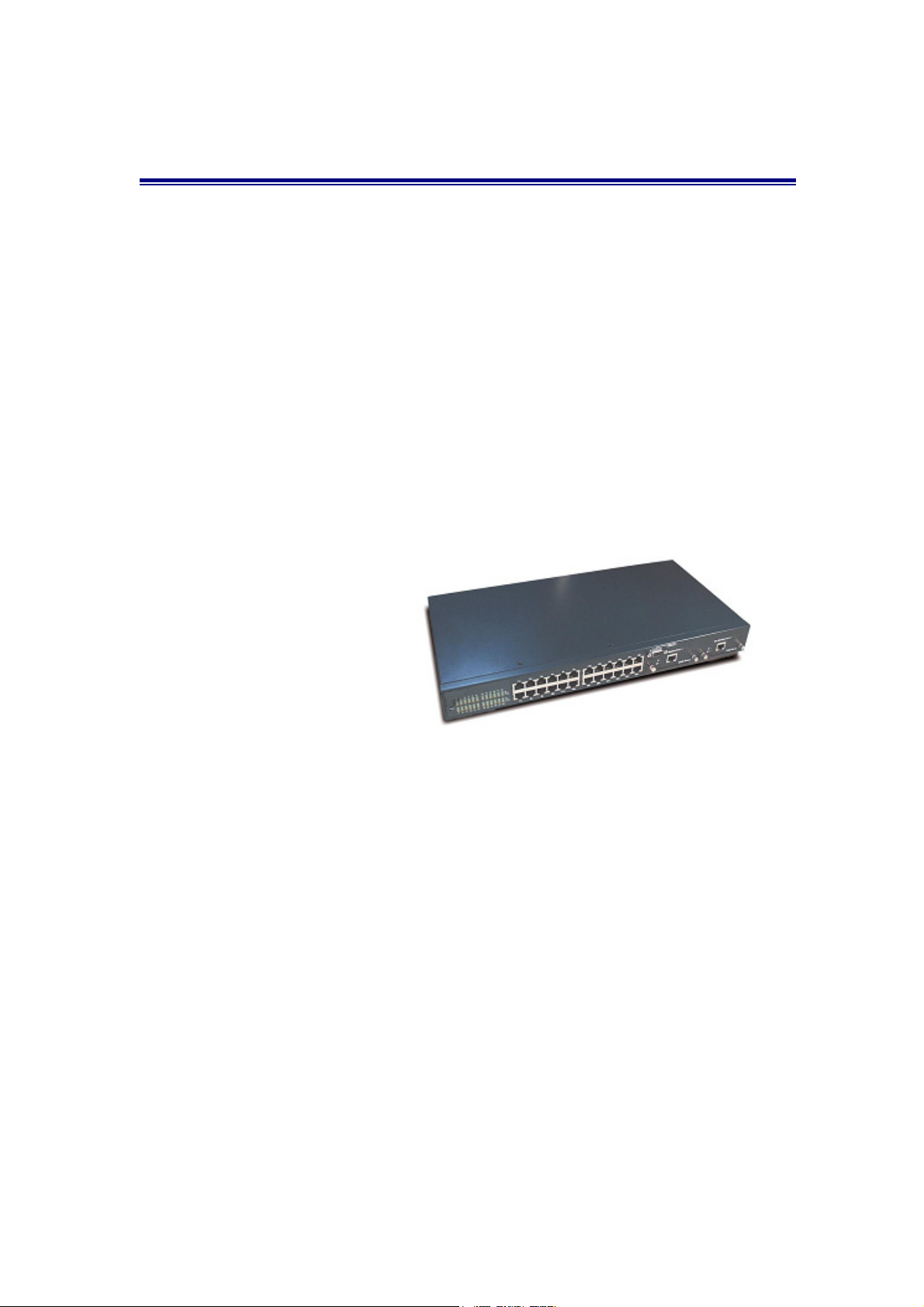
The SMC-EZ1026DT V.2 Switch is designed to provide your network
with Ethernet, Fast Ethernet, and Gigabit Ethernet connectivity over
twisted pair and fiber optic cabling. Two expansion slots on the front
panel of the SMC-EZ1026DT V.2 Switches further add to the
flexibility of the systems.
Figure 1-1. The
SMC-EZ1026DT V.2
The SMC-EZ1026DT V.2 is a Smart Fast Ethernet switch, that
provides a number of exceptional features with extremely flexible
configuration expansions without compromising the wire speed
performance.
The SMC-EZ1026DT V.2 switch provide wire-speed switching with
advanced bridging functions like VLAN, link aggregation (Trunk) and
port mirroring. It can also support two different GBIC type as Mini
GBIC LC and standard GBIC SC.
3
Page 4

SMC-EZ1026DT V.2
1.1 Features
▓ Conforms to IEEE802.3,IEEE 802.3 ab,
IEEE802.3u,IEEE802.3z ,IEEE802.3x IEEE802.1p
24 auto-sensing 10/100Mbps Ethernet RJ-45 ports
2 Expansion slots for optional modules: 1-port Gigabit
( SX/LX ), 1-port Gigabit Copper, and 1-port 100M Fiber
Module
Automatic MDI/MDIX crossover for each 10/100Base-TX port
One Console-connecting port for communication parameter
configuration
Auto-negotiation & Full-duplex/half-duplex supported
Store-and- Forward error free packet forwarding scheme
8K-entry MAC address table
6Mbits share memory
Full wire speed forwarding rate
LED-indicators for Power, 10/100M, LK/ACT, FD/ COL
statuses
Intelligent Management Features
Console Configuration
Port Based VLAN supported
IEEE802.3x Flow Control Mechanism is used in Full-Duplex
mode and back-pressure is used in half-duplex
Link Aggregation function supported
Port Mirror supported
Bandwidth Control
4
Page 5
SMC-EZ1026DT V.2
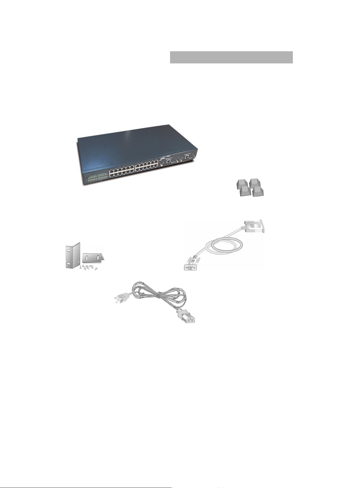
1.2 Package Contents
Unpack the carton of the SMC-EZ1026DT V.2 Switch and verify
them against the checklist below.
SMC-EZ1026DT V.2 Switch Rubber Feet
Rack-mounted Kit RS-232 cable
Power Cord
Figure 1-2. Package Contents
Compare the contents of your SMC-EZ1026DT V.2 Switch package
with the standard checklist above. If any item is missing or damaged,
please contact your local dealer for service.
5
Page 6
SMC-EZ1026DT V.2
2. Hardware Description
This section mainly describes the hardware of the SMC-EZ1026DT
V.2, and gives a functional overview of the Switch.
The physical dimensions of the SMC-EZ1026DT V.2 is: 440mmx
225mmx 44.5mm ( L x W x H )
2.1 Hardware Description
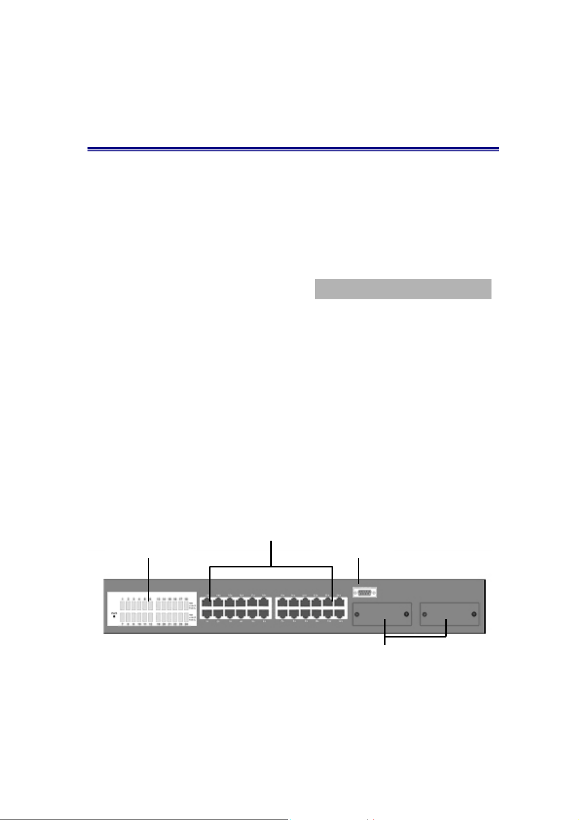
The SMC-EZ1026DT V.2 Switch has fixed 24-port auto-sensing
Ethernet RJ-45 connectors, and its chassis contains two expansion
slots.
The Front Panel
The Front Panel of the SMC-EZ1026DT V.2 consists of 24x
auto-sensing 10/100Mbps Ethernet RJ-45 Ports, two optional
expansion slots, and Console port. The LED Indicators are also
located on the front panel of the Switch.
LED Indicators
RJ-45 Ports
Console Port
Expansion Slots for Optional Module
Figure 2-1. The Front Panel of SMC-EZ1026DT V.2 Switch
6
Page 7
SMC-EZ1026DT V.2
10/100Base-TX RJ-45 ports (Auto MDI / MDIX):
24x 10/100Mbps auto-sensing port for 10Base-T or 100Base-TX
devices connection. Note: [MDI/MDIX means that you can connect
to another Switch or workstation without changing non-crossover or
crossover cable.]
Expansion Slots:
For two of the following Optional modules:
1 Port Gigabit 1000Base-T Intelligent Switch Modules,
1 Port Gigabit 1000Base-SX/LX Intelligent Fiber Modules.
1 Port 100Base-FX Intelligent Fiber Module
GBIC/Mini GBIC Module
Console Port:
Console Management can be done through the Console Port. It
requires a direct connection between the SMC-EZ1026DT V.2
Switch and an end station (PC) via a RS-232 cable.
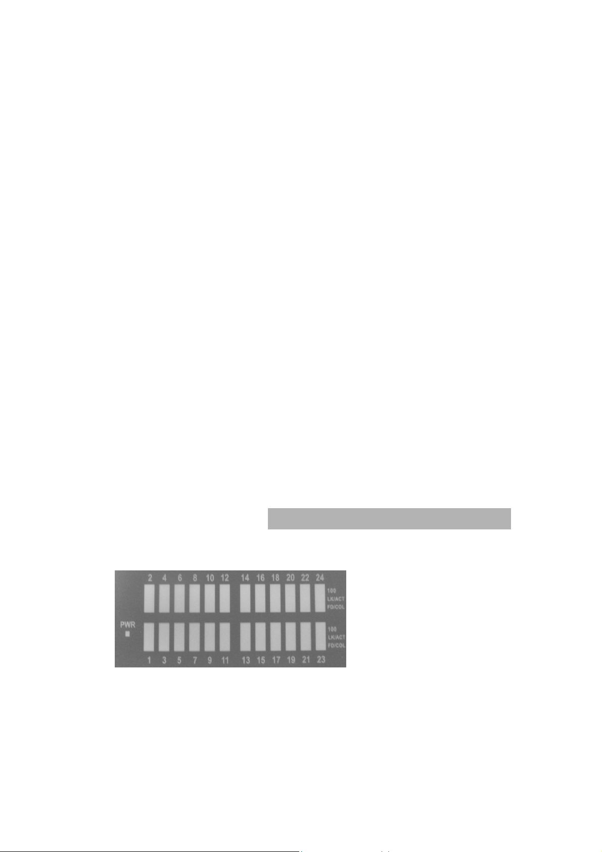
2.2 LED Indicators
Figure 2-2 The LED
Indicators
All LED indicators are located on the front panel of the
SMC-EZ1026DT V.2 Switch. They provide a real-time indication of
system and operational status. The following table
gives descriptions of the LED status and their meanings.
7
Page 8
SMC-EZ1026DT V.2
LED Status
Green Power On
PWR
Off Power is Off.
Green The port is operating at the speed of 100Mbps.
100
Off No device attached or in 10Mbps mode
Green The port is connecting with the device.
LK/ACT
Blinks The port is receiving or transmitting data.
Off No device attached.
Yellow The port is operating in Full-duplex mode.
Description
FD/COL
Blinks Collision of Packets occurs in the port.
Off No device attached or in half-duplex mode .
Table 2-3. The Descriptions of LED Indicators
Rear Panel
The 3-pronged power plug, On/Off switch are located at the Rear
Panel of the SMC-EZ1026DT V.2 Switch. (The Ventilation fan is
located on the side of the switch). The Switch will work with AC in
the range 100-240V AC, 50-60Hz.
Figure 2-4. The Rear Panel of the SMC-EZ1026DT V.2 Switch
8
Page 9

SMC-EZ1026DT V.2
Power On
After all network cables are connected, plug the power cord into the
power socket on the back panel and the other end into a power
outlet. Turn the power On using the power switch on the back panel.
Check the front panel Power indicator to see if power is properly
supplied. The Switch uses a universal power supply that requires no
additional adjustment.
3. Connecting to the Network
This section provides the installation procedure and instructions for
assigning IP address.
3.1 Pre-Installation Requirements
Before you start hardware installation, make sure your installation
environment has below items:
PCs with 10/100Mbps Ethernet NICs/100/1000Mbps Fiber
NICs:
Your PC must have a standard Ethernet interface to connect to
the Switch.
UTP cable with RJ45 connectors/ Fiber cable with MT-RJ/
VF-45 connectors: Check if the cable and connectors work
properly.
A power outlet: 100 to 240V AC at 50 to 60 Hz: Make sure that
the Switch power is accessible and cables can be connected
easily.
Dedicated power supply: Use a dedicated power circuits or
power conditioners to supply reliable electrical power to the
network devices.
A dry cool place: Keep the Switch away from moisture. Avoid
9
Page 10

SMC-EZ1026DT V.2
direct sunlight, heat source, and high amount of electromagnetic
interference around.
Mounting tools: If you intend to mount the Switch on a rack,
make sure you have all the tools, mounting brackets, screws etc.
Caution:
Cabling must be away from sources of electrical noise such as
radio, computers, transmitters, broadband amplifiers, power
lines and keep away from TVs, hair dryers, and microwave.
Airflow around the Switch and through its vents on the rear
cannot be restricted.
3.2 Mounting the Switch
The SMC-EZ1026DT V.2 Switch is suitable for use in an office
environment where it can be rack-mounted in standard EIA 19-inch
racks or standalone.
Desktop Mounting
1. Set the Switch on a sufficiently large flat space with a power
outlet nearby, and about the center of all networked devices.
2. Make sure mounting surface on the bottom of the Switch is
grease dust free.
3. Remove adhesive backing from your Rubber Feet.
Figure 3-1. Attaching Rubber Feet to each corner
on the bottom of the Switch
10
Page 11

SMC-EZ1026DT V.2
4. Apply the Rubber Feet to each corner on the bottom of the Switch.
These footpads can prevent the Switch from shock/vibrations.
Caution: Do not place objects on top of the Switch.
Rack-mounted Installation
The SMC-EZ1026DT V.2 Switch come with a rack-mounted kit and
can be mounted in an EIA standard size, 19-inch Rack. The Switch
can be placed in a wiring closet with other equipment.
Perform the following steps to rack mount the Switch:
A. Position one bracket to align with the holes on one side of the
Switch and secure it with the smaller bracket screws. Then attach
the remaining bracket to the other side of the Switch.
Figure 3-2. Attach mounting brackets with screws
B. After attached both mounting brackets, position the
SMC-EZ1026DT V.2 Switch ( UTP/MT-RJ/VF-45 ) in the rack by
lining up the holes in the brackets with the appropriate holes on
the rack. Secure the Switch to the rack with a screwdriver and the
rack-mounting screws.
11
Page 12

SMC-EZ1026DT V.2
Figure 3-3. Mount the 24TP+1Fiber Module Switch in an EIA
Standard 19-inch Rack
Note: For proper ventilation, allow about at least 4 inches (10 cm) of
clearance on the front and 3.4 inches ( 8 cm ) on the back of the
Switch. This is especially important for enclosed rack installation.
3.3 Connecting to the Switch
The Console port is a female DB-9 connector that enables a
connection to a PC or terminal for monitoring and configuring the
SMC-EZ1026DT V.2 Switch. Use the supplied RS-232 cable with a
male DB-9 connector to connect a terminal or PC to the Console
port.
The Console configuration (out of band) allow you to set your Switch
to enable a user at a remote console terminal to communicate with
the SMC-EZ1026DT V.2 Switch as if the console terminal were
directly connected to it.
12
Page 13

SMC-EZ1026DT V.2
Figure 3-4. Connecting the SMC-EZ1026DT V.2 Switch
to a terminal via RS-232 cable
3.4 Login in the Console Interface
When the connection between Switch and PC is finished, turn on the
PC and run a terminal emulation program or Hyper Terminal and
configure its communication parameters to match the following
default characteristics of the console port:
Baud Rate: 19200 bps
Data Bits: 8
Parity: none
Stop Bit: 1
Control flow: None
13
Page 14

SMC-EZ1026DT V.2
Figure 3-5. The settings of communication parameters
After you have finished parameter settings, click “OK“. When the screen
shows above, press “admin“ Key for the Password, then the Main Menu
of console management appears.
Main Menu
Figure 3-6. The screen of Main Menu
After login, you will see the main menu screen as illustrated in the picture.
The main menu displays all the sub-menu and pages that are available
in the console interface.
14
Page 15

SMC-EZ1026DT V.2
A. Device Configuration
Figure 3-7. The Device Configuration menu
Pick up the selection you would like to change the status and to toggle
the Enable / Disable field and type in appropriate value in the Aging Time
and Priority field.
Figure 3-8. The Device Configuration Setup menu
• Broadcast Storm Prevention can be set to 6% or 20% beside Disable.
The percentage indicates the allowance against the capacity. When its
disable there will be no limitation on the incoming rate of broadcast /
traffic, otherwise limitation on those traffics will be set to the percentage
15
Page 16

SMC-EZ1026DT V.2
accordingly.
•There are two different mode of VLAN supported in this system – Port
Base VLAN, MTU/MDU. The choice you made here will ultimately decide
the VLAN mode and function for entire system (the configuration of the
other two VLAN mode will have no effect to the system behavior).
B. Port Configuration
Figure 3-9. The Port Configuration Menu
The Ports (24+2) of the system are divided and displayed in three
separated pages. Use PREV PAGE, NEXT PAGE to list desired port
range and select the port.
In the port configuration screen you can configure the common
characteristics such as speed negotiation, and flow control, as well
as the following special features provided with the system:
• Bandwidth provisioning - 8 levels of speed control facilitate the
provisioning control for access provider.
16
Page 17

SMC-EZ1026DT V.2
C. Port Statistics
Figure 3-10. The Port Statistics Menu
You can view the statistics information display in this screen regarding a
certain port by entering the port number. You can also refresh or reset
the counter as you wish.
D. Port Based VLAN Configuration
Figure 3-11. The Port Based VLAN Configuration
Assigning physical ports within workgroup is simple, and is a common
method of defining a virtual workgroup – VLAN. It delivers the benefit of
17
Page 18

SMC-EZ1026DT V.2
broadcast control and simplifies configuration for the network manager.
One advantage of the Port-Based VLAN is its simplicity and easy to
configure, however, limited security is its drawback – anyone can plug
into the port and gain access to the VLAN.
Port Based VLAN Setup
Figure 3-12. The Port Based VLAN Setup Menu
Select the VLAN entry to create, modifies, or deletes the VLAN group.
Use <Space Bar> to check (join) or quit port(s) to the VLAN group.
E. Trunk Configuration
Figure 3-13. The Trunk Configuration Menu
18
Page 19

SMC-EZ1026DT V.2
Multiple links between switches can be grouped (trunk) to work as one
virtual, aggregate link. You can create 4 trunks at a time; each trunk can
hold up to 8 ports - only ports of the same speed can belong to a single
trunk.
Figure 3-14. The Trunk Configuration selection Menu
F. Mirror Configuration
Figure 3-15. The Mirror Configuration Menu
By enabling port mirroring, traffic to and from the source port will be
forwarded to the target port. You can select any of the 26 port as either
the Source port or the Target port by using <Space Bar> to scroll though
the desired port number
.
19
Page 20

SMC-EZ1026DT V.2
G. System Setup
Figure 3-16. The System Setup menu
The system can let you to reset all configuration or restart the device as
you wish anytime.
H. User Password
Figure 3-17. The User Password menu
The menu provides user to change their password for security use.
20
Page 21

SMC-EZ1026DT V.2
4. Network Configuration
This section provides you a few samples of network topology in
which SMC-EZ1026DT V.2 Switch ( UTP/MT-RJ/VF-45, Intelligent )
is used.
The Switch provides versatile configuration options for the network.
It is ideally suited as a workgroup or segment Switch in a network; it
has the flexibility to provide Switched 10Mbps to the desktop or
shared hubs, aggregate traffic from workgroup Switches, or provide
dedicated 100Mbps or 1000Mbps ( Gigabit ) to servers with
bandwidth-intensive applications. And because all Fast Ethernet
ports auto-negotiate for operation at 100 Mbps the Switch is
perfectly suited to an evolving network environment where demand
for network speed is increasing.
4.1 Collapsed Backbone Application
For small network where rapid growth can be expected in the near
future, this Switch is an ideal solution supporting backbone
connectivity.
The Switch can be used as a standalone Switch for a group of heavy
traffic users. Switching is brought to the desktop either through a
single end-station per Switch port or through a multi-port Switch.
A 1000 Mbps server is connected to the Switch, providing end
stations high-speed accessibility to its applications. This
configuration provides dedicated 100 Mbps connections to the
network center and to the server.
When the network needs expansion, you can simply connect the
Switch to any IEEE 802.3 (Ethernet), IEEE 802.3u (Fast Ethernet )
and 802.3ab (Gigabit Ethernet ) compliant Switch utilizing the Auto
MDI/MDIX function. This Switch can also cooperate with a wide
range of networking devices (e.g., firewall routers and printer
servers) added to the network.
21
Page 22

SMC-EZ1026DT V.2
Figure 4-1. Collapsed Backbone Application
4.2 Departmental Bridge
For enterprise networks where large data broadcasts are constantly
processed, this Switch is an ideal solution for department users to
connect to the corporate backbone. The SMC-EZ1026DT V.2 Switch
used as segment Switch can alleviate user contention for bandwidth
and eliminate server and network bottlenecks. All ports can connect
to high-speed department servers that need high bandwidth. This
Switch provides parallel communications within it’s Gigabit port,
which can run up to 2000 Mbps at Full-duplex.
The Switch makes key servers available to more users by allowing
multiple conversations to occur concurrently, thereby significantly
expanding overall network throughput. Moreover, this Switch eases
supervision and maintenance by allowing network manager
centralize multiple servers in a single location.
22
Page 23

SMC-EZ1026DT V.2
Figure 4-2: Departmental Bridge Application
NOTE: Full-duplex operation only applies to point-to-point access (for
example, when attaching the Switch to a workstation, server, or another
Switch). When connecting to hubs, use a standard cascaded connection
set for half-duplex operation.
4.3 High Performance Switched Workgroup
This Switch is also a good solution for connecting two workgroups,
supporting the throughput, for example, of 800Mbps. This
application is useful for power groups that need high bandwidth.
The most common LAN implementations use a combination of
standard switches, bridges and routers. The bridges and routers
quickly become bottlenecks, reducing overall network throughput.
Switching to higher-speed LANs such as FDDI or ATM is not a good
choice for most people.
However, such broadband equipment is still extremely expensive
and hard to maintain. Besides, you have to replace all existing
Ethernet cable and adapter cards, restructure your network, and
implement more expensive administration procedures.
23
Page 24

SMC-EZ1026DT V.2
The Switch can provide the same bandwidth of FDDI and ATM at
much lower costs. In addition, all current adapters and network
devices can still be used. The Switching cross-domain connection is
better than bridge and router because users can retain LAN
structure in which any node can freely communicate with any other
node.
Figure 4-3: High Performance Switched Workgroup Application
4.4. VLAN Application
Port-based VLAN Workgroup
You can group the Switch ports into broadcast domains by assigning
them to the same VLAN to increase network capacity and
performance. With network segmentation, each Switch port
connects to a segment that is a single broadcast domain. Packets
received in one VLAN can only be forwarded within that VLAN.
VLAN allows the grouping of end stations logically, based not on
physical location but on business policies such as job function or
department. Members of a group can be dispersed throughout a
facility - they do not have to be connected in close physical
locations.
24
Page 25

SMC-EZ1026DT V.2
Hence, group members can coordinate their data communication
requirements regardless of the actual working locations; and the
logical network can extend to any point you want it to. Moreover,
VLAN groups can be modified at any time to add, move or change
users without any re-cabling.
Figure 4-4: VLAN Workgroup Application
Shared Server
The Switch compliant to the IEEE802.1Q tagging VLAN standard
allows ports to exist in multiple VLANs for shared resources, such as
servers, printers, and Switch-to-Switch connections. It is also
possible to have resources exist in multiple VLANs on one Switch as
shown in the following figure.
25
Page 26

SMC-EZ1026DT V.2
Figure 4-5: Shared Server
In this example, stations on different VLANs share resources. As a
result, VLAN 1 and VLAN 2 can access VLAN 3 for printing. The
broadcasts from ports configured in VLAN3 can be seen by all VLAN
port members of VLAN3.
26
Page 27

SMC-EZ1026DT V.2
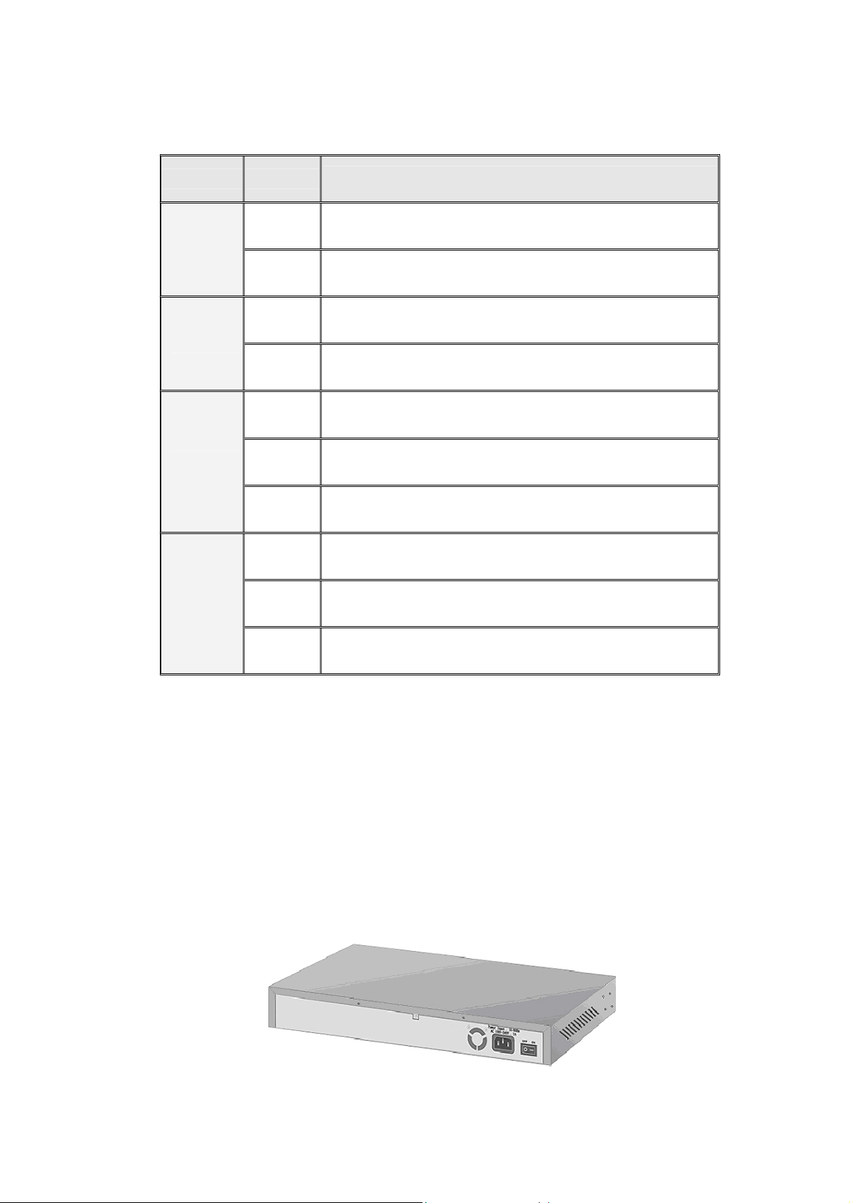
5. Product Specifications
This section provides the specifications of SMC-EZ1026DT V.2
Switch, and the following table lists them.
Standards Compliance
Protocol CSMA/CD
Media Connector Basic unit: 24 RJ-45 for STP or UTP,
Transfer Rate 14880 Packets per second for 10Mbps
Backplane Bandwidth 9.6Gbps
Switch Technology Store-and-Forward Error Free Packet Forwarding
MAC Address 8K MAC address with auto learning function
Data Buffer 6Mbits share memory
LED System Power, per port Link/active,
Dimension 440mm(W)*225mm(D)*44.5mm(H)
Power 100~240 VAC 50/60HZ
EMI & Safety FCC Class A, CE, UL
IEEE802.3 10BASE-T
IEEE802.3u 100BASE-TX and 100BASE-FX
IEEE802.3ab 1000BASE-T
IEEE802.3z 1000BASE-SX/LX
IEEE802.3x Flow Control
Auto MDI/MDI-X Support
100M FX Module: SC, MTRJ, VF45
Gigabit SX/LX Module: 1 Duplex SC
Gigabit 1000T Module: 1 RJ-45 for UTP or STP,
Auto MDI/MDI-X Support
GBIC: Mini GBIC LC type, Standard GBIC SC type
148800 packets per second for 100Mbps
1488000 packets per second for 1000Mbps
Scheme
Supports Hardware Level Broadcast Storm
Prevention without Consuming System CPU
Utilization
FDX/Col,10/100Mbps
27
 Loading...