

Page 1

ES4700 Series
Chassis Core Routing
Switch
1
www.smc.com
Page 2

Preface
ES4700 Series Chassis Core Routing Switch is a high performance routing switch
released by SMC Networks that can be deployed as the core layer device for campus and
enterprise networks, or as an aggregation device for IP metropolitan area networks
(MAN). ES4700 Series Chassis Core Routing Switch provides 4 and 10 slots, with
support for various types of line cards and can seamlessly support a variety of network
interfaces from 100Mb, 1000Mb to 10 GB Ethernet.
We are providing this manual for your better understanding, use and maintenance of
the ES4700 Series Chassis Core Routing Switch. We strongly recommend you to read
through this manual carefully before installation and configuration to avoid possible
malfunction or damage to the switch. Furthermore, we sincerely hope our products and
services satisfy you.
2
Page 3

Content
CHAPTER 1 SWITCH MANAGEMENT.......................................................................... 18
1.1 MANAGEMENT OPTIONS ....................................................................................... 18
1.1.1 Out-of-band Management .............................................................................. 18
1.1.2 In-band Management ..................................................................................... 21
1.1.3 Management via Telnet................................................................................... 21
1.1.4 Management via HTTP................................................................................... 24
1.2 MANAGEMENT INTERFACE..................................................................................... 27
1.2.1 CLI Interface................................................................................................... 27
1.2.2 Configuration Modes ...................................................................................... 27
1.2.3 Configuration Syntax ...................................................................................... 30
1.2.4 Shortcut Key Support ..................................................................................... 31
1.2.5 Help function................................................................................................... 32
1.2.6 Input verification ............................................................................................. 32
1.2.7 Fuzzy match support ...................................................................................... 33
1.3 WEB MANAGEMENT.............................................................................................. 33
1.3.1 Main Page ...................................................................................................... 33
1.3.2 Module Front Panel ........................................................................................ 33
CHAPTER 2 BASIC SWITCH CONFIGURATION.......................................................... 35
2.1 COMMANDS FOR BASIC SWITCH CONFIGURATION .................................................. 35
2.1.1 Command For Basic Configuration................................................................. 35
2.2 COMMANDS FOR MAINTENANCE AND DEBUG.......................................................... 49
2.2.1 Ping ................................................................................................................ 49
2.2.2 Ping6 .............................................................................................................. 50
2.2.3 Telnet.............................................................................................................. 50
2.2.4 SSH ................................................................................................................ 53
2.2.5 Traceroute ...................................................................................................... 56
2.2.6 Traceroute6 .................................................................................................... 56
2.2.7 Show .............................................................................................................. 57
2.2.8 Debug............................................................................................................. 62
2.2.9 System log...................................................................................................... 63
2.3 CONFIGURATE SWITCH IP ADDRESSES .................................................................. 68
2.3.1 Switch IP Addresses Configuration Task List.................................................. 69
2.3.2 Commands For Configuring Switch IP............................................................ 69
2.4 SNMP CONFIGURATION ....................................................................................... 71
2.4.1 Introduce to SNMP ......................................................................................... 71
2.4.2 SNMP Configuration Task List ........................................................................ 74
3
Page 4

2.4.3 Command For SNMP ..................................................................................... 76
2.4.4 Typical SNMP Configuration Examples .......................................................... 85
2.4.5 SNMP Troubleshooting Help .......................................................................... 87
2.5 SWITCH UPGRADE................................................................................................ 87
2.5.1 Switch System Files ....................................................................................... 87
2.5.2 BootROM Upgrade ......................................................................................... 88
2.5.3 FTP/TFTP Upgrade ........................................................................................ 90
2.5.4 FTP/TFTP Configuration Examples................................................................ 98
2.5.5 FTP/TFTP Troubleshooting Help .................................................................. 102
2.6 SECURITY FEATURE CONFIGURATION .................................................................. 104
2.6.1 Security Feature Introduction........................................................................ 104
2.6.2 Security Feature Configuration ..................................................................... 104
2.6.3 Commands for Security Feature................................................................... 106
2.6.4 Security Feature Example .............................................................................110
2.7 JUMBO CONFIGURATION ......................................................................................110
2.7.1 Jumbo Introduction ........................................................................................11 0
2.7.2 Jumbo Configuration Task Sequence ............................................................110
2.7.3 Jumbo Command ..........................................................................................111
2.8 SFLOW CONFIGURATION......................................................................................111
2.8.1 sFlow introduction..........................................................................................111
2.8.2 sFlow Configuration Task...............................................................................112
2.8.3 Commands For sFlow ...................................................................................113
2.8.4 sFlow Examples ............................................................................................118
2.8.5 sFlow Troubleshooting...................................................................................118
2.9 TACACS+ CONFIGURATION ................................................................................119
2.9.1 TACACS+ Introduction ..................................................................................119
2.9.2 TACACS+ Configurations ..............................................................................119
2.9.3 Commands for TACACS+............................................................................. 120
2.9.4 Typical TACACS+ Scenarios ........................................................................ 122
2.9.5 TACACS+ Troubleshooting........................................................................... 122
2.10 WEB MANAGEMENT.......................................................................................... 123
2.10.1 Switch basic configuration .......................................................................... 123
2.10.2 SNMP configuration.................................................................................... 124
2.10.3 Switch upgrade........................................................................................... 126
2.10.4 Maintenance and debug command ............................................................ 129
2.10.5 Basic introduction to switch ........................................................................ 130
2.10.6 Switch Maintenance ................................................................................... 131
2.10.7 Telnet server configuration.......................................................................... 131
4
Page 5

2.10.8 Telnet server user configuration.................................................................. 132
2.10.9 Telnet security IP ........................................................................................ 132
CHAPTER 3 DEVICE MANAGEMENT ........................................................................ 133
3.1 DEVICE MANAGEMENT BRIEF .............................................................................. 133
3.2 DEVICE MANAGEMENT CONFIGURATION .............................................................. 133
3.2.1 Switch Basic Configuration........................................................................... 133
3.3 DEVICE MANAGEMENT TROUBLESHOOTING HELP................................................. 133
3.3.1 Monitor and Debug Command...................................................................... 133
3.4 CARD HOT-SWAP OPERATION............................................................................. 135
3.4.1 Card Hot-Insertion ........................................................................................ 135
3.4.2 Card Hot-Remove......................................................................................... 135
3.5 CONFIGURATION RESTORATION RULES................................................................ 136
3.6 ACTIVE-STANDB Y ALTERNATION .......................................................................... 136
3.7 COMMAND FOR DEVICE MANAGEMENT ................................................................. 137
3.7.1 debug devsm ................................................................................................ 137
3.7.2 force runcfg-sync .......................................................................................... 137
3.7.3 force switchover............................................................................................ 137
3.7.4 reset slot....................................................................................................... 137
3.7.5 runcfg-sync................................................................................................... 138
3.7.6 show fan ....................................................................................................... 138
3.7.7 show power .................................................................................................. 139
3.7.8 show slot ...................................................................................................... 139
CHAPTER 4 PORT CONFIGURATION........................................................................ 140
4.1 INTRODUCTION TO PORT..................................................................................... 140
4.2 PORT CONFIGURATION ....................................................................................... 141
4.2.1 Network Port Configuration........................................................................... 141
4.2.2 VLAN Interface Configuration....................................................................... 150
4.2.3 Network Management Port Configuration..................................................... 151
4.3 PORT MIRRORING CONFIGURATION ..................................................................... 155
4.3.1 Introduction to Port Mirroring ........................................................................ 155
4.3.2 Port Mirroring Configuration Task List........................................................... 155
4.3.3 Command For Mirroring Configuration ......................................................... 155
4.3.4 Device Mirroring Troubleshooting Help......................................................... 156
4.4 PORT CONFIGURATION EXAMPLE ........................................................................ 157
4.5 PORT TROUBLESHOOTING HELP.......................................................................... 158
4.6 WEB MANAGEMENT............................................................................................ 158
4.6.1 Ethernet port configuration ........................................................................... 158
4.6.2 Physical port configuration ........................................................................... 158
5
Page 6

4.6.3 Bandwidth control ......................................................................................... 159
4.6.4 Vlan interface configuration .......................................................................... 160
4.6.5 Allocate IP address for L3 port...................................................................... 160
4.6.6 L3 port IP addr mode configuration .............................................................. 160
4.6.7 Port mirroring configuration .......................................................................... 161
4.6.8 Mirror configuration....................................................................................... 161
4.6.9 Port debug and maintenance........................................................................ 161
4.6.10 Show port information................................................................................. 161
CHAPTER 5 PORT CHANNEL CONFIGURATION ..................................................... 163
5.1 INTRODUCTION TO PORT CHANNEL...................................................................... 163
5.2 PORT CHANNEL CONFIGURATION ........................................................................ 164
5.2.1 Port Channel Configuration Task List ........................................................... 164
5.2.2 Command for port channel ........................................................................... 165
5.3 PORT CHANNEL EXAMPLE................................................................................... 171
5.4 PORT CHANNEL TROUBLESHOOTING HELP........................................................... 173
5.5 WEB MANAGEMENT............................................................................................ 174
5.5.1 LACP port group configuration ..................................................................... 174
5.5.2 LACP port configuration................................................................................ 175
CHAPTER 6 VLAN CONFIGURATION ........................................................................ 176
6.1 VLAN CONFIGURATION ...................................................................................... 176
6.1.1 Introduction to VLAN .................................................................................... 176
6.1.2 VLAN Configuration Task List ....................................................................... 177
6.1.3 Command for vlan Configuration .................................................................. 178
6.1.4 Typical VLAN Application.............................................................................. 184
6.2 GVRP CONFIGURATION...................................................................................... 186
6.2.1 Introduction to GVRP.................................................................................... 186
6.2.2 GVRP Configuration Task List ...................................................................... 186
6.2.3 Command For GVRP ................................................................................... 187
6.2.4 Typical GVRP Application............................................................................. 190
6.2.5 GVRP Troubleshooting Help......................................................................... 192
6.3 DOT1Q-TUNNEL CONFIGURATION ........................................................................ 193
6.3.1 Dot1q-tunnel Introduction ............................................................................. 193
6.3.2 Dot1q-tunnel Configuration........................................................................... 194
6.3.3 Dot1q-Tunnel Configuration Command ........................................................ 194
6.3.4 Typical Applications Of The Dot1q-tunnel ..................................................... 196
6.3.5 Dot1q-tunnel Troubleshooting....................................................................... 197
6.4 VLAN-TRANSLATION CONFIGURATION ................................................................. 198
6.4.1 VLAN-translation Introduction....................................................................... 198
6
Page 7

6.4.2 Configuration Task Sequence Of VLAN-translation ...................................... 198
6.4.3 VLAN-translation Configuration Command................................................... 199
6.4.4 Typical Application Of VLAN-translation ....................................................... 201
6.4.5 VLAN-translation Troubleshooting................................................................ 202
6.5 DYNAMIC VLAN CONFIGURATION........................................................................ 202
6.5.1 Dynamic VLAN Introduction.......................................................................... 202
6.5.2 Dynamic VLAN Configuration....................................................................... 203
6.5.3 Typical Application Of The Dynamic VLAN ................................................... 209
6.5.4 Dynamic VLAN Troubleshooting................................................................... 210
6.6 VOICE VLAN CONFIGURATION .............................................................................211
6.6.1 Voice VLAN Introduction................................................................................211
6.6.2 Voice VLAN Configuration .............................................................................211
6.6.3 Typical Applications Of The Voice VLAN ...................................................... 214
6.6.4 Voice VLAN Troubleshooting........................................................................ 215
CHAPTER 7 MAC TABLE CONFIGURATION............................................................. 216
7.1 INTRODUCTION TO MAC TABLE ........................................................................... 216
7.1.1 Obtaining MAC Table.................................................................................... 216
7.1.2 Forward or Filter ........................................................................................... 218
7.2 MAC ADDRESS TABLE CONFIGURATION TASK LIST ................................................ 219
7.3 COMMANDS FOR MAC ADDRESS TABLE CONFIGURATION ...................................... 219
7.3.1 mac-address-table........................................................................................ 219
7.3.2 show mac-address-table............................................................................... 220
7.4 TYPICAL CONFIGURATION EXAMPLES................................................................... 221
7.5 TROUBLESHOOTING HELP................................................................................... 221
7.6 MAC ADDRESS FUNCTION EXTENSION ................................................................ 222
7.6.1 MAC Address Binding................................................................................... 222
CHAPTER 8 MSTP CONFIGURATION........................................................................ 230
8.1 MSTP INTRODUCTION ........................................................................................ 230
8.1.1 MSTP Region ............................................................................................... 230
8.1.2 Port Roles..................................................................................................... 232
8.1.3 MSTP Load Balance..................................................................................... 232
8.2 MSTP CONFIGURATION TASK LIST ...................................................................... 232
8.3 COMMAND FOR MSTP........................................................................................ 236
8.3.1 abort ............................................................................................................. 236
8.3.2 exit................................................................................................................ 236
8.3.3 instance vlan................................................................................................. 237
8.3.4 name ............................................................................................................ 237
8.3.5 revision-level................................................................................................. 238
7
Page 8

8.3.6 spanning-tree................................................................................................ 238
8.3.7 spanning-tree format .................................................................................... 239
8.3.8 spanning-tree forward-time........................................................................... 239
8.3.9 spanning-tree hello-time ............................................................................... 240
8.3.10 spanning-tree link-type p2p ........................................................................ 240
8.3.11 spanning-tree maxage ................................................................................ 241
8.3.12 spanning-tree max-hop............................................................................... 241
8.3.13 spanning-tree mcheck ................................................................................ 242
8.3.14 spanning-tree mode.................................................................................... 242
8.3.15 spanning-tree mst configuration ................................................................. 242
8.3.16 spanning-tree mst cost ............................................................................... 243
8.3.17 spanning-tree mst port-priority.................................................................... 244
8.3.18 spanning-tree mst priority ........................................................................... 244
8.3.19 spanning-tree portfast................................................................................. 245
8.3.20 spanning-tree digest-snooping ................................................................... 245
8.3.21 spanning-tree tcflush (global mode) ........................................................... 246
8.3.22 spanning-tree tcflush (port mode)............................................................... 246
8.4 MSTP EXAMPLE ................................................................................................ 247
8.5 MSTP TROUBLESHOOTING HELP ........................................................................ 252
8.5.1 Monitor And Debug Command ..................................................................... 252
8.6 WEB MANAGEMENT............................................................................................ 256
8.6.1 MSTP field operation .................................................................................... 256
8.6.2 MSTP port operation..................................................................................... 257
8.6.3 MSTP global control ..................................................................................... 258
8.6.4 Show MSTP setting ...................................................................................... 259
CHAPTER 9 QOS AND PBR CONFIGURATION......................................................... 261
9.1 QOS CONFIGURATION ........................................................................................ 261
9.1.1 Introduction to QoS....................................................................................... 261
9.1.2 QoS Configuration Task List ......................................................................... 266
9.1.3 Command for QoS........................................................................................ 270
9.1.4 QoS Example ............................................................................................... 280
9.1.5 QoS Troubleshooting Help ........................................................................... 282
9.2 PBR CONFIGURATION ........................................................................................ 287
9.2.1 Introduction to PBR ...................................................................................... 287
9.2.2 PBR configuration......................................................................................... 287
9.2.3 PBR examples.............................................................................................. 288
CHAPTER 10 L3 FORWARD CONFIGURATION........................................................ 290
10.1 LAYE R 3 INTERFACE ......................................................................................... 290
8
Page 9

10.1.1 Introduction to Layer 3 Interface................................................................. 290
10.1.2 Layer 3 Interface Configuration Task List.................................................... 290
10.1.3 Command for Layer 3 Interface .................................................................. 291
10.2 IP CONFIGURATION .......................................................................................... 291
10.2.1 Introduction to IPv4, IPv6 ........................................................................... 291
10.2.2 IPv4 Configuration ...................................................................................... 293
10.2.3 IPv6 Configuration ...................................................................................... 294
10.2.4 IP Configuration Examples ......................................................................... 308
10.2.5 IP Troubleshooting Help ............................................................................. 313
10.3 IP FORWARDING............................................................................................... 323
10.3.1 Introduction to IP Forwarding...................................................................... 323
10.3.2 IP Route Aggregation Configuration Task ................................................... 323
10.3.3 Command for IP Route Aggregation........................................................... 324
10.4 URPF ............................................................................................................. 324
10.4.1 URPF Introduction ...................................................................................... 324
10.4.2 URPF Operation Mechanism...................................................................... 325
10.4.3 URPF Configuration Task Sequence .......................................................... 325
10.4.4 Commands For URPF ................................................................................ 326
10.4.5 URPF Troubleshooting ............................................................................... 327
10.5 ARP................................................................................................................ 327
10.5.1 Introduction to ARP..................................................................................... 327
10.5.2 ARP Configuration Task List ....................................................................... 328
10.5.3 Command for ARP Configuration ............................................................... 328
CHAPTER 11 DHCP CONFIGURATION...................................................................... 332
11.1 INTRODUCTION TO DHCP ................................................................................. 332
11.2 DHCP SERVER CONFIGURATION....................................................................... 333
11.2.1 DHCP Sever Configuration Task List .......................................................... 333
11.2.2 Commands for DHCP Server Configuration ............................................... 335
11.3 DHCP RELAY CONFIGURATION ......................................................................... 343
11.3.1 DHCP Relay Configuration Task List .......................................................... 344
11.3.2 Commands for DHCP Relay Configuration................................................. 345
11.4 DHCP CONFIGURATION EXAMPLE ..................................................................... 347
11.5 DHCP TROUBLESHOOTING HELP ...................................................................... 350
11.5.1 Commands for Monitor and Debug ............................................................. 350
11.6 WEB MANAGEMENT.......................................................................................... 353
11.6.1 DHCP server configuration ......................................................................... 353
11.6.2 DHCP debugging ........................................................................................ 358
CHAPTER 12 SNTP CONFIGURATION ...................................................................... 360
9
Page 10

12.1 INTRODUCTION TO SNTP.................................................................................. 360
12.2 COMMAND FOR SNTP...................................................................................... 361
12.2.1 clock timezone............................................................................................ 361
12.2.2 sntp server.................................................................................................. 361
12.2.3 sntp poll ...................................................................................................... 362
12.2.4 debug sntp.................................................................................................. 362
12.2.5 show sntp ................................................................................................... 362
12.3 TYPICAL SNTP CONFIGURATION EXAMPLES ...................................................... 363
12.4 WEB MANAGEMENT.......................................................................................... 363
12.4.1 SNMP/NTP server configuration................................................................. 363
12.4.2 Request interval configuration .................................................................... 364
12.4.3 Time difference........................................................................................... 364
12.4.4 Show SNTP................................................................................................ 364
CHAPTER 13 PREVENT ARP, ND SPOOFING CONFIGURATION............................ 365
13.1 OVERVIEW....................................................................................................... 365
13.1.1 ARP ( Address Resolution Protocol) ........................................................... 365
13.1.2 ARP Spoofing ............................................................................................. 365
13.1.3 How to prevent void ARP/ND Spoofing for our Layer 3 Switch ................... 366
13.2 PREVENT ARP, ND SPOOFING CONFIGURATION ................................................. 366
13.2.1 Prevent ARP, ND Spoofing Configuration Task List .................................... 366
13.3 COMMANDS FOR PREVENTING ARP, ND SPOOFING ........................................... 367
13.3.1 ip arp-security updateprotect ...................................................................... 367
13.3.2 ipv6 nd-security updateprotect.................................................................... 368
13.3.3 ip arp-security learnprotect ......................................................................... 368
13.3.4 ipv6 nd learnprotect .................................................................................... 368
13.3.5 ip arp-security convert ................................................................................ 369
13.3.6 ipv6 nd-security convert.............................................................................. 369
13.3.7 clear ip arp dynamic ................................................................................... 369
13.3.8 clear ipv6 nd dynamic................................................................................. 369
13.4 PREVENT ARP, ND SPOOFING EXAMPLE ........................................................... 370
CHAPTER 14 ROUTING PROTOCOL......................................................................... 372
14.1 ROUTING PROTOCOL OVERVIEW ....................................................................... 372
14.1.1 Routing Table.............................................................................................. 373
14.2 IP ROUTING POLICY ......................................................................................... 374
14.2.1 Introduction To Routing Policy .................................................................... 374
14.2.2 IP Routing Policy Configuration Task List ................................................... 376
14.2.3 Command For Routing Policy..................................................................... 380
14.2.4 Configuration Examples ............................................................................. 392
10
Page 11

14.2.5 Troubleshooting Help.................................................................................. 393
14.3 STATI C ROUTE ................................................................................................. 396
14.3.1 Introduction to Static Route......................................................................... 396
14.3.2 Introduction to Default Route...................................................................... 396
14.3.3 Static Route Configuration Task List........................................................... 397
14.3.4 Command For Static Route ........................................................................ 397
14.3.5 Configuration Examples ............................................................................. 401
14.4 RIP ................................................................................................................. 402
14.4.1 Introduction to RIP...................................................................................... 402
14.4.2 RIP Configuration Task List ........................................................................ 404
14.4.3 Command For RIP...................................................................................... 410
14.4.4 RIP Examples............................................................................................. 425
14.4.5 Troubleshooting Help Of RIP...................................................................... 428
14.5 RIPNG............................................................................................................. 435
14.5.1 Introduction to RIPng.................................................................................. 435
14.5.2 RIPng Configuration Task List .................................................................... 437
14.5.3 Commands For RIPng................................................................................ 440
14.5.4 RIPng Configuration Examples................................................................... 445
14.5.5 RIPng Troubleshooting Help....................................................................... 447
14.6 OSPF ............................................................................................................. 451
14.6.1 Introduction to OSPF .................................................................................. 451
14.6.2 OSPF Configuration Task List..................................................................... 454
14.6.3 Command For OSPF.................................................................................. 459
14.6.4 OSPF Example........................................................................................... 479
14.6.5 OSPF Troubleshooting Help....................................................................... 488
14.7 OSPFV3 ......................................................................................................... 496
14.7.1 Introduction to OSPFv3 .............................................................................. 496
14.7.2 OSPFv3 Configuration Task List................................................................. 500
14.7.3 Command For OSPFV3 ............................................................................. 503
14.7.4 OSPFv3 Examples ..................................................................................... 513
14.7.5 OSPFv3 Troubleshooting Help ................................................................... 516
14.8 BGP ............................................................................................................... 523
14.8.1 BGP Introduction ........................................................................................ 523
14.8.2 BGP Configuration Task List....................................................................... 527
14.8.3 Command For BGP .................................................................................... 540
14.8.4 Configuration Examples of BGP................................................................. 579
14.8.5 BGP Troubleshooting Help ......................................................................... 587
14.9 MBGP4+ ........................................................................................................ 597
11
Page 12

14.9.1 MBGP4+ Introduction ................................................................................. 597
14.9.2 MBGP4+ Configures Mission List............................................................... 598
14.9.3 MBGP4+ Examples .................................................................................... 598
14.9.4 MBGP4+ Troubleshooting Help.................................................................. 600
CHAPTER 15 IGMP SNOOPING ................................................................................. 601
15.1 INTRODUCTION TO IGMP SNOOPING ................................................................. 601
15.2 IGMP SNOOPING CONFIGURATION TASK ........................................................... 601
15.3 COMMAND FOR IGMP SNOOPING ..................................................................... 603
15.3.1 ip igmp snooping vlan................................................................................. 603
15.3.2 ip igmp snooping vlan immediate-leave...................................................... 603
15.3.3 ip igmp snooping vlan l2-general-querier.................................................... 603
15.3.4 ip igmp snooping vlan limit.......................................................................... 604
15.3.5 ip igmp snooping vlan mrouter-port interface.............................................. 604
15.3.6 ip igmp snooping vlan mrpt......................................................................... 605
15.3.7 ip igmp snooping vlan query-interval .......................................................... 605
15.3.8 ip igmp snooping vlan query-mrsp.............................................................. 606
15.3.9 ip igmp snooping vlan query-robustness .................................................... 606
15.3.10 ip igmp snooping vlan suppression-query-time......................................... 606
15.4 IGMP SNOOPING EXAMPLE .............................................................................. 607
15.5 IGMP SNOOPING TROUBLESHOOTING HELP ...................................................... 609
15.5.1 Monitor And Debug Command ................................................................... 609
CHAPTER 16 MULTICAST VLAN................................................................................613
16.1 INTRODUCTION TO MULTICAST VLAN................................................................ 613
16.2 MULTICAST VLAN CONFIGURATION TASK .......................................................... 613
16.3 COMMANDS FOR MULTICAST VLAN .................................................................. 614
16.3.1 multicast-vlan.............................................................................................. 614
16.3.2 multicast-vlan association........................................................................... 614
16.4 EXAMPLES OF MULTICAST VLAN ...................................................................... 615
CHAPTER 17 IPV4 MULTICAST PROTOCOL ............................................................ 617
17.1 IPV4 MULTICAST PROTOCOL OVERVIEW ............................................................ 617
17.1.1 Introduction to Multicast.............................................................................. 617
17.1.2 Multicast Address ....................................................................................... 618
17.1.3 IP Multicast Packet Transmission ............................................................... 619
17.1.4 IP Multicast Application............................................................................... 620
17.2 PIM-DM.......................................................................................................... 620
17.2.1 Introduction to PIM-DM............................................................................... 620
17.2.2 PIM-DM Configuration Task List ................................................................. 622
17.2.3 Command for PIM-DM................................................................................ 623
12
Page 13

17.2.4 PIM-DM Configuration Examples ............................................................... 624
17.2.5 PIM-DM Troubleshooting............................................................................ 625
17.3 PIM-SM .......................................................................................................... 628
17.3.1 Introduction to PIM-SM............................................................................... 628
17.3.2 PIM-SM Configuration Task List ................................................................. 630
17.3.3 Command For PIM-SM............................................................................... 632
17.3.4 PIM-SM Configuration Examples................................................................ 641
17.3.5 PIM-SM Troubleshooting............................................................................ 643
17.4 DVMRP .......................................................................................................... 652
17.4.1 Introduction to DVMRP............................................................................... 652
17.4.2 Configuration Task List ............................................................................... 654
17.4.3 Command For DVMRP............................................................................... 655
17.4.4 DVMRP Configuration Examples................................................................ 658
17.4.5 DVMRP TroubleShooting............................................................................ 659
17.5 ECSCM .......................................................................................................... 663
17.5.1 Introduction to ECSCM............................................................................... 663
17.5.2 ECSCM Configuration Task List ................................................................. 664
17.5.3 Command For ECSCM............................................................................... 667
17.5.4 ECSCM Configuration Examples................................................................ 672
17.5.5 ECSCM Troubleshooting............................................................................ 673
17.6 IGMP.............................................................................................................. 675
17.6.1 Introduction to IGMP................................................................................... 675
17.6.2 Configuration Task List ............................................................................... 677
17.6.3 Command For IGMP .................................................................................. 679
17.6.4 IGMP Configuration Example ..................................................................... 684
17.6.5 IGMP Troubleshooting................................................................................ 685
CHAPTER 18 IPV6 MULTICAST PROTOCOL ............................................................ 689
18.1 PIM-DM6........................................................................................................ 689
18.1.1 Introduction to PIM-DM6............................................................................. 689
18.1.2 PIM-DM Configuration Task List ................................................................. 690
18.1.3 Command for PIM-DM6.............................................................................. 691
18.1.4 PIM-DM Typical Application........................................................................ 695
18.1.5 PIM-DM Troubleshooting Help.................................................................... 696
18.2 PIM-SM6 ........................................................................................................ 699
18.2.1 Introduction to PIM-SM6............................................................................. 699
18.2.2 PIM-SM Configuration Task List ................................................................. 700
18.2.3 Command for PIM-SM................................................................................ 703
18.2.4 PIM-SM Typical Application .........................................................................711
13
Page 14

18.2.5 PIM-SM Troubleshooting Help.................................................................... 713
18.3 MLD ............................................................................................................... 722
18.3.1 Introduction to MLD .................................................................................... 722
18.3.2 MLD Configuration Task List....................................................................... 723
18.3.3 Command for MLD ..................................................................................... 725
18.3.4 MLD Typical Application.............................................................................. 730
18.3.5 MLD Troubleshooting Help ......................................................................... 731
18.4 MLD SNOOPING............................................................................................... 734
18.4.1 MLD Snooping Introduction ........................................................................ 734
18.4.2 MLD Snooping Configuration Task ............................................................. 734
18.4.3 Commands For MLD Snooping Configuration ............................................ 736
18.4.4 MLD Snooping Examples ........................................................................... 742
18.4.5 MLD Snooping Troubleshooting ................................................................. 745
CHAPTER 19 ACL CONFIGURATION......................................................................... 746
19.1 INTRODUCTION TO ACL .................................................................................... 746
19.1.1 Access-list................................................................................................... 746
19.1.2 Access-group.............................................................................................. 746
19.1.3 Access-list Action and Global Default Action............................................... 747
19.2 ACL CONFIGURATION ....................................................................................... 747
19.2.1 ACL Configuration Task Sequence ............................................................. 747
19.2.2 Commands for ACL .................................................................................... 760
19.3 ACL EXAMPLE ................................................................................................. 779
19.4 ACL TROUBLESHOOTING .................................................................................. 780
19.4.1 Monitor And Debug Command ................................................................... 780
19.5 WEB MANAGEMENT.......................................................................................... 783
19.5.1 Numeric standard ACL configuration .......................................................... 784
19.5.2 Delete numeric IP ACL ............................................................................... 784
19.5.3 Configure the numeric extended ACL......................................................... 784
19.5.4 Configure and delete the standard ACL name ............................................ 786
19.5.5 Configure extended ACL name configuration ............................................. 787
19.5.6 Firewall configuration.................................................................................. 787
19.5.7 ACL port binding ......................................................................................... 787
CHAPTER 20 802.1X CONFIGURATION .................................................................... 789
20.1 INTRODUCTION TO 802.1X ................................................................................ 789
20.2 802.1X CONFIGURATION................................................................................... 790
20.2.1 802.1x Configuration Task Sequence ......................................................... 790
20.2.2 Command for 802.1x .................................................................................. 794
20.3 802.1X APPLICATION EXAMPLE ......................................................................... 803
14
Page 15

20.3.1 802.1x Troubleshooting .............................................................................. 804
20.4 WEB MANAGEMENT.......................................................................................... 810
20.4.1 RADIUS client configuration ....................................................................... 810
20.4.2 802.1X configuration................................................................................... 812
CHAPTER 21 VRRP CONFIGURATION...................................................................... 816
21.1 INTRODUCTION TO VRRP................................................................................. 816
21.2 VRRP CONFIGURATION TASK LIST .................................................................... 817
21.3 COMMANDS FOR VRRP ................................................................................... 819
21.3.1 advertisement-interval ................................................................................ 819
21.3.2 circuit-failover ............................................................................................. 819
21.3.3 debug vrrp .................................................................................................. 820
21.3.4 disable ........................................................................................................ 820
21.3.5 enable......................................................................................................... 821
21.3.6 interface...................................................................................................... 821
21.3.7 preempt-mode ............................................................................................ 821
21.3.8 priority......................................................................................................... 822
21.3.9 router vrrp................................................................................................... 822
21.3.10 show vrrp.................................................................................................. 823
21.3.11 virtual-ip .................................................................................................... 823
21.4 EXAMPLE OF VRRP......................................................................................... 824
21.5 VRRP TROUBLESHOOTING ............................................................................... 825
21.6 WEB MANAGEMENT.......................................................................................... 825
21.6.1 Create VRRP Number ................................................................................ 825
21.6.2 configure VRRP Dummy IP ........................................................................ 826
21.6.3 configure VRRP Port .................................................................................. 826
21.6.4 Activate Virtual Router ................................................................................ 826
21.6.5 Configure Preemptive Mode For VRRP...................................................... 826
21.6.6 Configure VRRP Priority............................................................................. 827
21.6.7 Configure VRRP Interval ............................................................................ 827
21.6.8 Configure VRRP Circuit.............................................................................. 827
21.6.9 Configure VRRP Authentication Mode........................................................ 827
CHAPTER 22 MRPP CONFIGURATION...................................................................... 829
22.1 MRPP INTRODUCTION...................................................................................... 829
22.1.1 Conception Introduction.............................................................................. 829
22.1.2 MRPP Protocol Packet Types..................................................................... 830
22.1.3 MRPP Protocol Operation System ............................................................. 831
22.2 MRPP CONFIGURATION TASK SEQUENCE ......................................................... 832
22.3 COMMANDS FOR MRPP................................................................................... 833
15
Page 16

22.3.1 clear mrpp statistics.................................................................................... 833
22.3.2 control-vlan................................................................................................. 833
22.3.3 debug mrpp ................................................................................................ 834
22.3.4 enable......................................................................................................... 834
22.3.5 fail-timer...................................................................................................... 835
22.3.6 hello-timer................................................................................................... 835
22.3.7 mrpp enable................................................................................................ 836
22.3.8 mrpp ring .................................................................................................... 836
22.3.9 node-mode ................................................................................................. 837
22.3.10 primary-port .............................................................................................. 837
22.3.11 secondary-port .......................................................................................... 837
22.3.12 show mrpp................................................................................................ 838
22.3.13 show mrpp statistics ................................................................................. 838
22.4 MRPP TYPICAL SCENARIO ................................................................................ 838
22.4.1 MRPP typical scenario 1............................................................................. 838
22.4.2 MRPP typical scenario 2............................................................................. 840
22.4.3 MRPP typical scenario 3............................................................................. 843
22.5 MRPP TROUBLESHOOTING ............................................................................... 847
CHAPTER 23 CLUSTER CONFIGURATION............................................................... 848
23.1 INTRODUCTION TO CLUSTER............................................................................. 848
23.2 CLUSTER MANAGEMENT CONFIGURATION SEQUENCE ........................................ 848
23.3 COMMANDS FOR CLUSTER ............................................................................... 851
23.3.1 cluster run................................................................................................... 851
23.3.2 cluster register timer ................................................................................... 851
23.3.3 cluster ip-pool ............................................................................................. 851
23.3.4 cluster commander ..................................................................................... 852
23.3.5 cluster member........................................................................................... 852
23.3.6 cluster auto-add enable .............................................................................. 853
23.3.7 rcommand member .................................................................................... 853
23.3.8 rcommand commander............................................................................... 854
23.3.9 cluster reset member.................................................................................. 854
23.3.10 cluster update member............................................................................. 854
23.3.11 cluster holdtime......................................................................................... 855
23.3.12 cluster heartbeat....................................................................................... 856
23.3.13 clear cluster candidate-table..................................................................... 856
23.4 EXAMPLES OF CLUSTER ADMINISTRATION ......................................................... 857
23.5 CLUSTER ADMINISTRATION TROUBLESHOOTING ................................................. 857
23.5.1 Cluster Debugging and Monitoring Command............................................ 857
16
Page 17

23.5.2 Cluster Administration Troubleshooting ...................................................... 859
17
Page 18

Chapter 1 Switch Management
1.1 Management Options
After purchasing the switch, the user needs to configure the switch for network
management. ES4700 series provides two management options: in-band management
and out-of-band management.
1.1.1 Out-of-band Management
Out-of-band management is the management through Console interface. Generally,
the user will use out-of-band management for the initial switch configuration, or when
in-band management is not available. For instance, the user must assign an IP address
to the switch via the Console interface to be able to access the switch through Telnet.
The procedures for managing the switch via Console interface are listed below:
Step 1: setting up the environment:
Connect with serial port
Fig 1-1 Out-of-band Management Configuration Environment
As shown in Fig 1-1, the serial port (RS-232) is connected to the switch with the
serial cable provided. The table below lists all the devices used in the connection.
Device Name Description
PC machine Has functional keyboard and RS-232, with terminal
emulator installed, such as HyperTerminal included in
Windows 9x/NT/2000/XP.
Serial port cable One end attach to the RS-232 serial port, the other end to
the Console port.
18
Page 19
ES4700 series Functional Console port required.
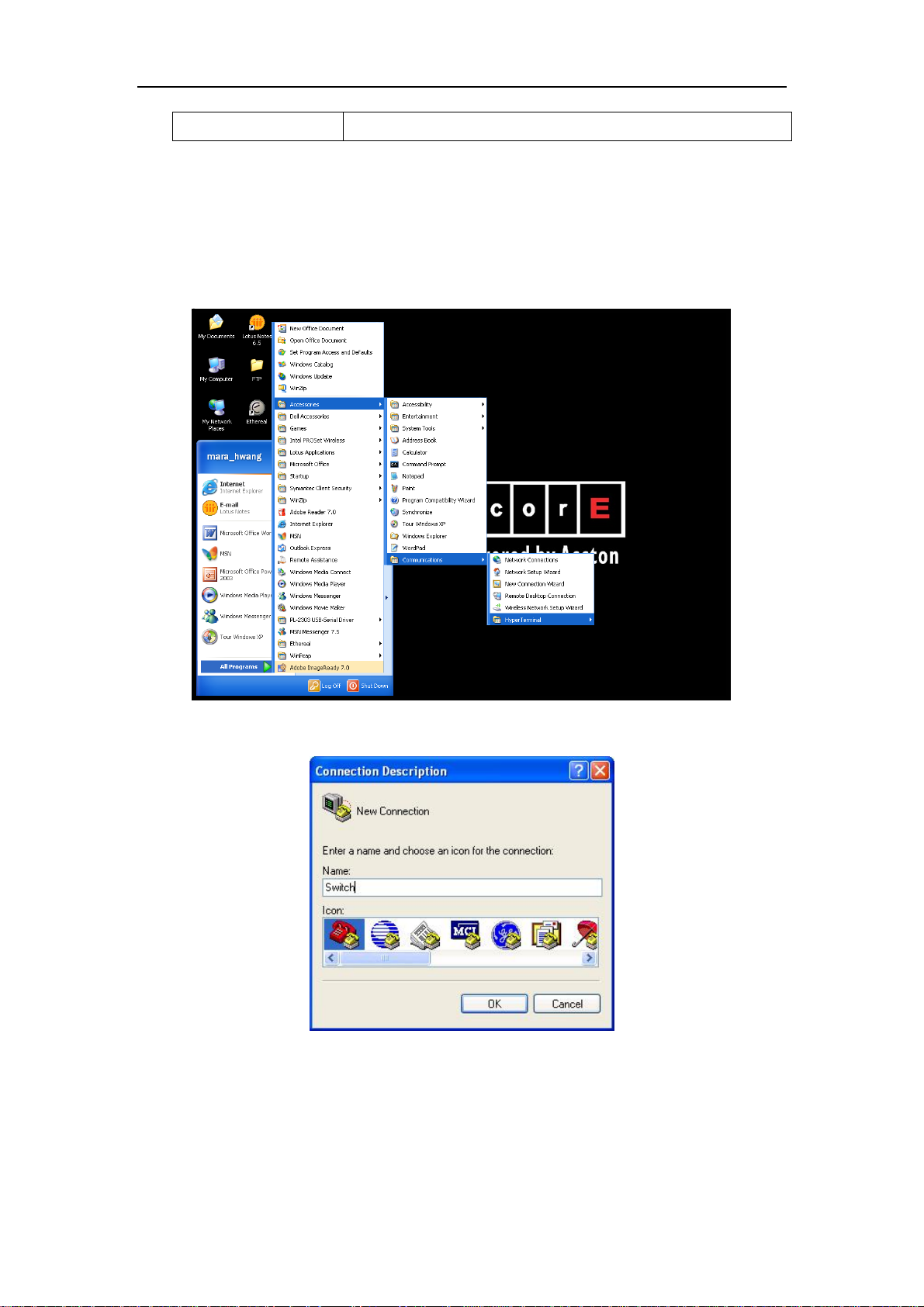
Step 2 Entering the HyperTerminal
Open the HyperTerminal included in Windows after the connection established. The
example below is based on the HyperTerminal included in Windows XP.
1) Click Start menu - All Programs -Accessories -Communication - HyperTerminal.
Fig 1-2 Opening HyperTerminal
2) Type a name for opening HyperTerminal, such as “Switch”.
Fig 1-3 Opening HyperTerminal
3) In the “Connecting with” drop-list, select the RS-232 serial port used by the PC, e.g.
COM1, and click “OK”.
19
Page 20
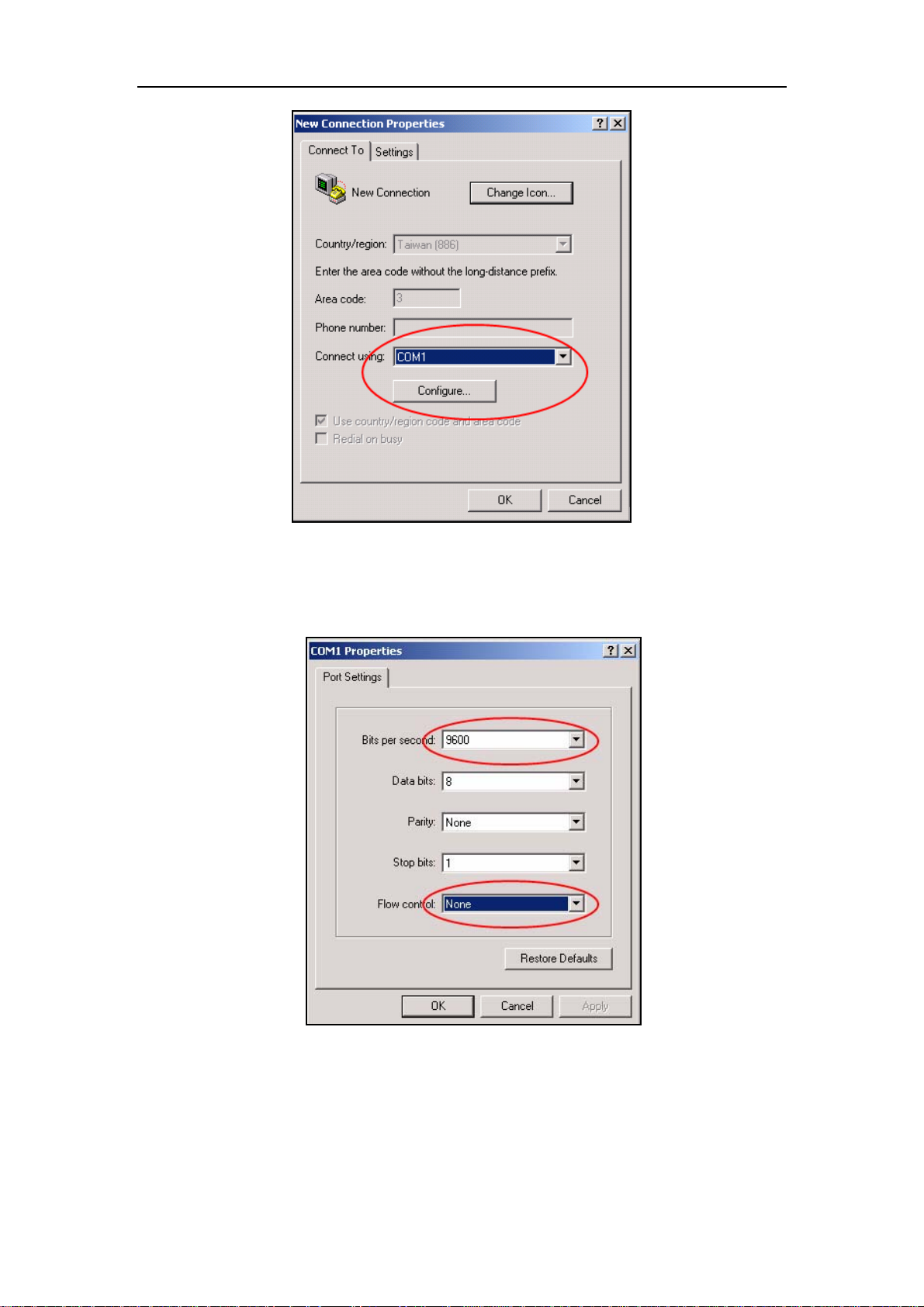
Fig 1-4 Opening HyperTerminal
4) COM1 property appears, select “9600” for “Baud rate”, “8” for “Data bits”, “none” for
“Parity checksum”, “1” for stop bit and “none” for traffic control; or, you can also click
“Revert to default” and click “OK”.
Fig 1-5 Opening HyperTerminal
Step 3 Entering switch CLI interface:
Power on the switch. The following appears in the HyperTerminal windows, that is
the CLI configuration mode for ES4700 series.
ES4700 series Management Switch
20
Page 21

Copyright (c) 2001-2006 by Accton Technology Corporation.
All rights reserved.
Reset chassis ... done.
Testing RAM...
134,217,728 RAM OK.
Initializing...
Attaching to file system ... done.
Loading nos.img ... done.
Starting at 0x10000...
Current time is WED APR 20 09: 37: 52 2005
ES4700 series Switch Operating System, Software Version ES4700 series 1.1.0.0,
Copyright (C) 2001-2006 by Accton Technology Corporation
http: //www.smc. com.
ES4700 series Switch
26 Ethernet/IEEE 802.3 interface(s)
Press ENTER to start session
The user can now enter commands to manage the switch. For a detailed description
for the commands, please refer to the following chapters.
1.1.2 In-band Management
In-band management refers to the management by login to the switch using
Telnet. In-band management enables management of the switch for some devices
attached to the switch. In the case when in-band management fails due to switch
configuration changes, out-of-band management can be used for configuring and
managing the switch.
1.1.3 Management via Telnet
To manage the switch with Telnet, the following conditions should be met:
1) Switch has an IP address configured
2) The host IP address (Telnet client) and the switch’s VLAN interface IP address is
in the same network segment.
3) If not 2), Telnet client can connect to an IP address of the switch via other
devices, such as a router.
ES4700 seriesis a Layer 3 switch that can be configured with several IP addresses.
The following example assumes the shipment status of the switch where only VLAN1
exists in the system.
21
Page 22

The following describes the steps for a Telnet client to connect to the switch’s VLAN1
interface by Telnet.
Fig 1-6 Manage the switch by Telnet
Step 1: Configure the IP addresses for the switch
First is the configuration of host IP address. This should be within the same network
segment as the switch VLAN1 interface IP address. Suppose the switch VLAN interface
IP address 10.1.128.251/24. Then, a possible host IP address is 10.1.128.252/24. Run
“ping 10.1.128.251” from the host and verify the result, check for reasons if ping failed.
The IP address configuration commands for VLAN1 interface are listed below.
Before in-band management, the switch must be configured with an IP address by
out-of-band management (i.e. Console mode), The configuration commands are as
follows (All switch configuration prompts are assumed to be “switch” hereafter if not
otherwise specified):
Switch>
Switch>en
Switch#config
Switch(Config)#interface vlan 1
Switch(Config-If-Vlan1)#ip address 10.1.128.251 255.255.255.0
Switch(Config-If-Vlan1)#no shutdown
Step 2: Run Telnet Client program.
Run Telnet client program included in Windows with the specified Telnet target.
22
Page 23

Fig 1-7 Run telnet client program included in Windows
Step 3: Login to the switch
Login to the Telnet configuration interface. Valid login name and password are
required, otherwise the switch will reject Telnet access. This is a method to protect the
switch from unauthorized access. As a result, when Telnet is enabled for configuring and
managing the switch, username and password for authorized Telnet users must be
configured with the following command:
username <user> password {0|7} <password>.
Assume an authorized user in the switch has a username of “test”, and password of
“test”, the configuration procedure should like the following:
Switch
>en
Switch#config
Switch(Config)#username test password 0 test
Enter valid login name and password in the Telnet configuration interface, Telnet
user will be able to enter the switch’s CLI configuration interface. The commands used in
the Telnet CLI interface after login is the same as in that in the Console interface.
23
Page 24

Fig 1-8 Telnet Configuration Interface
1.1.4 Management via HTTP
To manage the switch via HTTP, the following conditions should be met:
1) Switch has an IP address configured
2) The host IP address (HTTP client) and the switch’s VLAN interface IP address
are in the same network segment;
3) If 2) is not met, HTTP client should connect to an IP address of the switch via
other devices, such as a router.
Similar to management via Telnet, as soon as the host succeeds to ping an IP
address of the switch and to type the right login password, it can access the switch via
HTTP. The configuration list is as below:
Step 1: Configure the IP addresses for the switch and start the HTTP function on the
switch.
For configuring the IP address on the switch through out-of-band management, see
the relevant chapter.
To enable the WEB configuration, users should type the CLI command ip http
server in the global mode as below:
Switch
Switch#config
Switch(Config)#ip http server
>en
24
Page 25
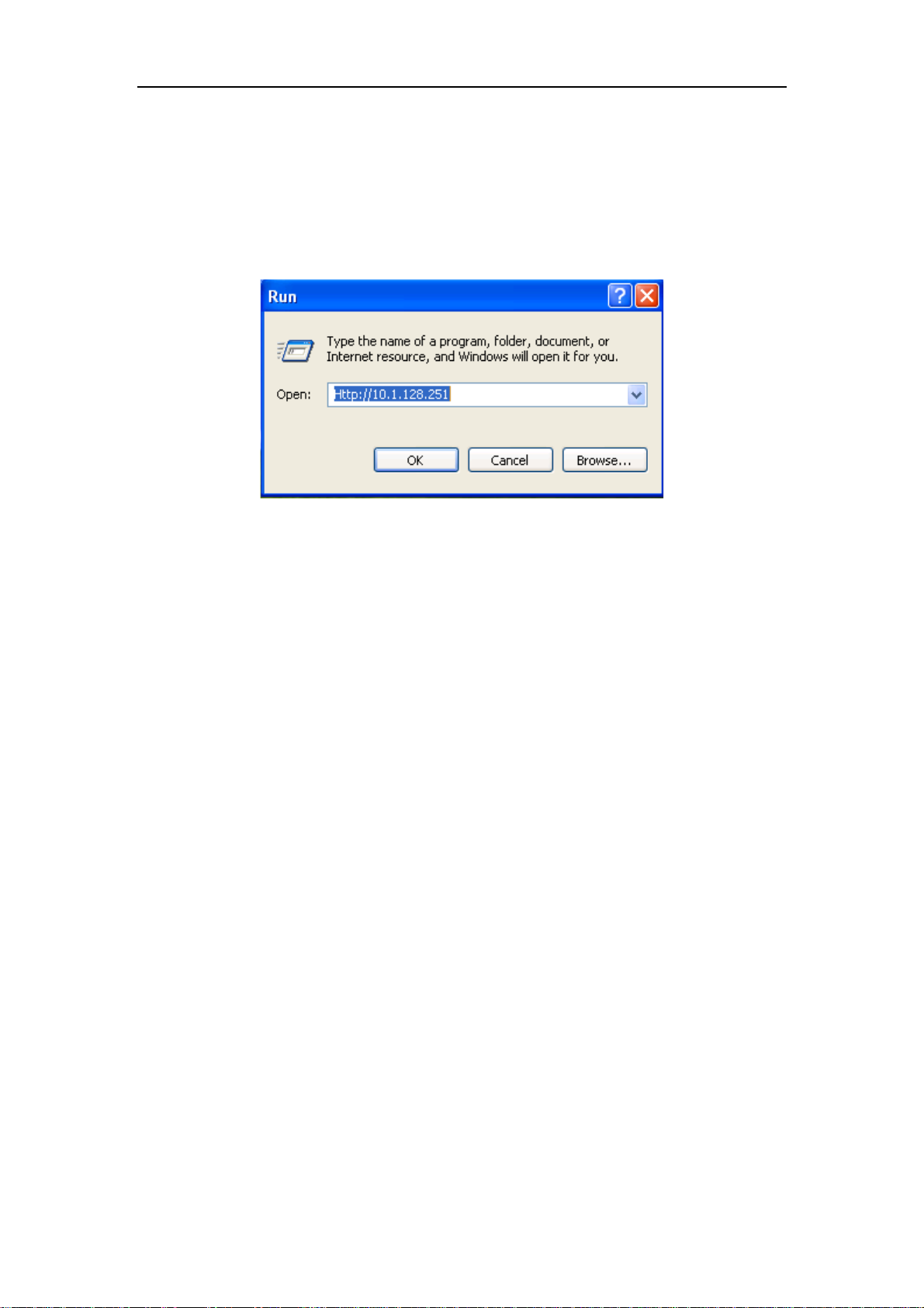
Step 2: Run HTTP protocol on the host.
Open the Web browser on the host and type the IP address of the switch. Or run
directly the HTTP protocol on the Windows. For example, the IP address of the switch is
“10.1.128.251”.
Fig 1-9 Run HTTP Protocol
When accessing a switch with IPv6 address, it is recommended to use the Firefox
browser with 1.5 or later version. For example, if the IPv6 address of the switch is
“3ffe:506:1:2::3”, enter the switch address at the address bar: http://[3ffe:506:1:2::3],
where the address should be in the square brackets.
Step 3: Logon to the switch
To logon to the HTTP configuration interface, valid login user name and password
are required; otherwise the switch will reject HTTP access. This is a method to protect
the switch from the unauthorized access. Consequently, in order to configure the switch
via HTTP, username and password for authorized HTTP users must be configured with
the following command in the global mode:
username <username> password <show_flag> <password>.
Suppose an authorized user in the switch has a username as “test”, and password
as “test”. The configuration procedure is as below:
Switch
>en
Switch#config
Switch(Config)# username test password 0 test
The Web login interface is as below:
25
Page 26
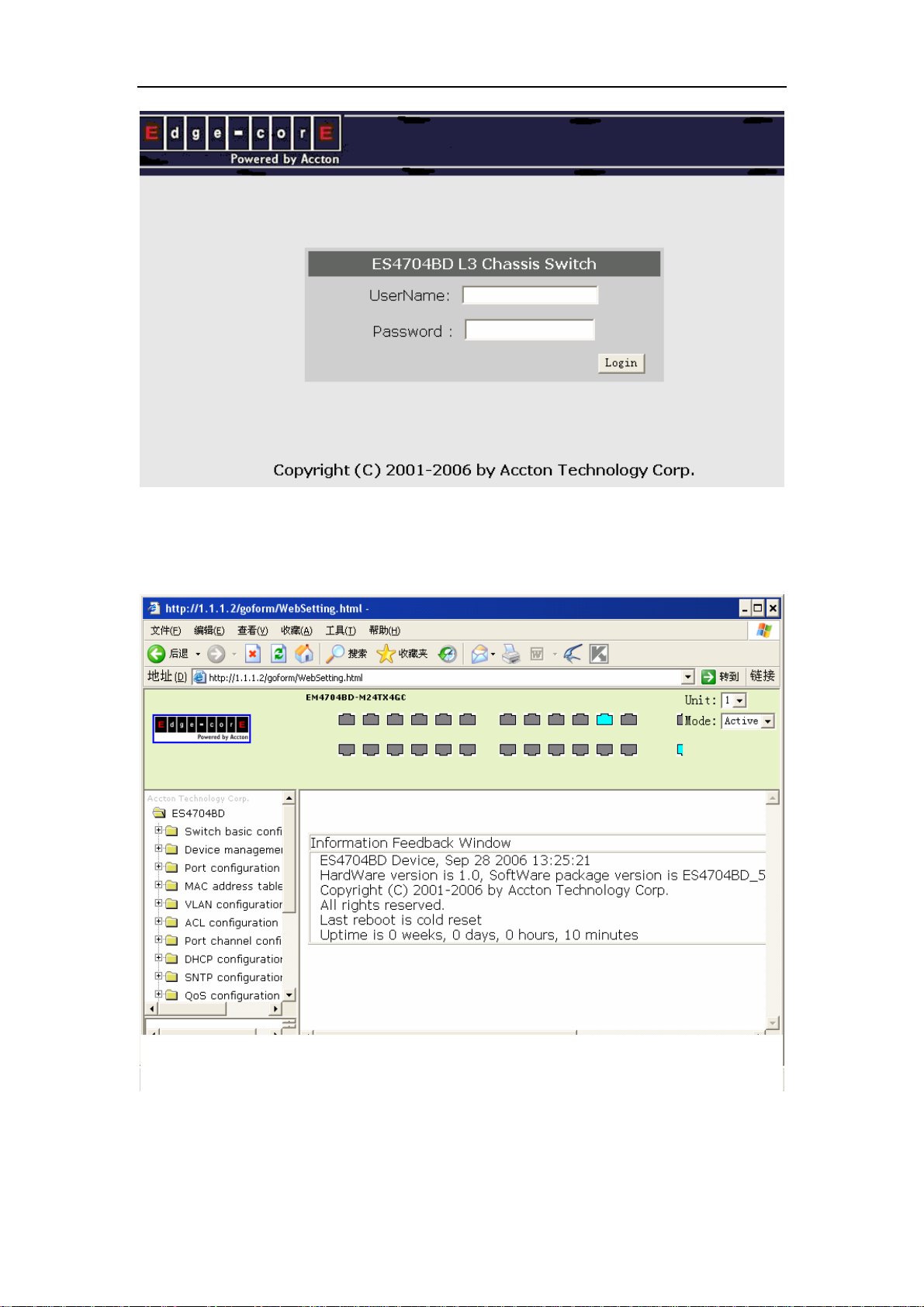
Fig 1-10 Web Login Interface
Input the right username and password, and then the main Web configuration
interface is shown as below.
Fig 1-11 Main Web Configuration Interface
26
Page 27

1.2 Management Interface
1.2.1 CLI Interface
CLI interface is familiar to most users. As aforementioned, out-of-band management
and Telnet login are all performed through CLI interface to manage the switch.
CLI Interface is supported by Shell program, which consists of a set of configuration
commands.Those commands are categorized according to their functions in switch
configuration and management. Each category represents a different configuration mode.
The Shell for the switch is described below:
z Configuration Modes
z Configuration Syntax
z Shortcut keys
z Help function
z Input verification
z Fuzzy match support
1.2.2 Configuration Modes
User Mode
Admin Mode
Global Mode
Interface Mode
Fig 1-12 Shell Configuration Modes
Vlan Mode
27
DHCP address pool
configuration mode
Route configuration
mode
ACL configuration
mode
Page 28

1.2.2.1 User Mode
On entering the CLI interface, entering user entry system first. If as common user, it
is defaulted to User Mode. The prompt shown is “Switch>“, the symbol “>“ is the prompt
for User Mode. When disable command is run under Admin Mode, it will also return to
the User Mode.
Under User Mode, no configuration to the switch is allowed, only clock time and
version information of the switch can be queries.
1.2.2.2 Admin Mode
To enter Admin Mode sees the following: In user entry system, if as Admin user, it is
defaulted to Admin Mode. Admin Mode prompt “Switch#” can be entered under the User
Mode by running the enable command and entering corresponding access levels admin
user password, if a password has been set. Or, when exit command is run under Global
Mode, it will also return to the Admin Mode. ES4700 series also provides a shortcut key
sequence "Ctrl+z”, this allows an easy way to exit to Admin Mode from any configuration
mode (except User Mode).
Under Admin Mode, when disable command is run, it will return to User Mode. When
exit command is run, it will exit the entry and enter user entry system direct. Next users
can reenter the system on entering corresponding user name and password.
Under Admin Mode, the user can query the switch configuration information,
connection status and traffic statistics of all ports; and the user can further enter the
Global Mode from Admin Mode to modify all configurations of the switch. For this reason,
a password must be set for entering Admin mode to prevent unauthorized access and
malicious modification to the switch.
1.2.2.3 Global Mode
Type the config command under Admin Mode will enter the Global Mode prompt
“Switch(Config)#”. Use the exit command under other configuration modes such as
Interface Mode, VLAN mode will return to Global Mode.
The user can perform global configuration settings under Global Mode, such as MAC
Table, Port Mirroring, VLAN creation, IGMP Snooping start, GVRP and STP, etc. And the
user can go further to Interface Mode for configuration of all the interfaces.
1.2.2.4 Interface Mode
Use the interface command under Global Mode can enter the interface mode
specified. ES4700 series provides three interface type: VLAN interface, Ethernet port and
28
Page 29

port-channel, and accordingly the three interface configuration modes.
Interface Type Entry Prompt Operates Exit
VLAN
Interface
Ethernet Port Type interface
port-channel Type interface
Type interface
vlan <Vlan-id>
command under
Global Mode.
ethernet
<interface-list>
command under
Global Mode.
port-channel
<port-channel-nu
mber> command
under Global
Mode.
Switch(Config-IfVlanx)#
Switch(Configethernetxx)#
Switch(Config-ifport-channelx)#
Configure
switch IPs, etc
Configure
supported
duplex mode,
speed, etc.
of Ethernet
Port.
Configure
port-channel
related
settings such
as duplex
mode, speed,
etc.
Use the exit
command to
return to
Global Mode.
Use the exit
command to
return to
Global Mode.
Use the exit
command to
return to
Global Mode.
1.2.2.5 VLAN Mode
Using the vlan <vlan-id> command under Global Mode can enter the corresponding
VLAN Mode. Under VLAN Mode the user can configure all member ports of the
corresponding VLAN. Run the exit command to exit the VLAN Mode to Global Mode.
1.2.2.6 DHCP Address Pool Mode
Type the ip dhcp pool <name> command under Global Mode will enter the DHCP
Address Pool Mode prompt “Switch(Config-<name>-dhcp)#”. DHCP address pool
properties can be configured under DHCP Address Pool Mode. Run the exit command to
exit the DHCP Address Pool Mode to Global Mode.
1.2.2.7 Route Mode
Routing
Protocol
Entry Prompt Operates Exit
RIP
Routing
Type router
rip
Switch(Config-Router-Rip)# Configure
RIP protocol
29
Use the
“exit”
Page 30

Protocol command
under
Global
Mode.
OSPF
Routing
Protocol
Type router
ospf
command
under
Global
Mode.
Switch(Config-Router-Ospf)# Configure
parameters. command to
return to
Global
Mode.
Use the
OSPF
protocol
parameters.
“exit”
command to
return to
Global
Mode.
1.2.2.8 ACL Mode
ACL type Entry Prompt Operates Exit
Standard IP
ACL Mode
Type
access-list ip
Switch(Config-Std-Nacla)#
Configure
parameters
Use the “exit”
command to
return to
Global Mode.
Use the “exit”
command to
return to
Global Mode.
Extended IP
ACL Mode
command
under Global
Mode.
Type
access-list ip
command
under Global
Mode.
Switch(Config-Ext-Naclb)#
for
Standard
IP ACL
Mode
Configure
parameters
for
Extended
IP ACL
Mode
1.2.3 Configuration Syntax
ES4700 series provides various configuration commands. Although all the
commands are different, they all abide by the syntax for ES4700 series configuration
commands. The general command format of ES4700 series is shown below:
cmdtxt <variable> { enum1 | … | enumN } [option]
Conventions: cmdtxt in bold font indicates a command keyword; <variable> indicates a
variable parameter; {enum1 | … | enumN } indicates a mandatory parameter that should
be selected from the parameter set enum1~enumN; and the square bracket ([ ]) in
[option] indicate an optional parameter. There may be combinations of “< >“, “{ }” and
30
Page 31

“[ ]” in the command line, such as [<variable>],{enum1 <variable>| enum2}, [option1
[option2]], etc.
Here are examples for some actual configuration commands:
y show calendar, no parameters required. This is a command with only a
keyword and no parameter, just type in the command to run.
y vlan <vlan-id>, parameter values are required after the keyword.
y duplex {auto|full|half}, user can enter duplex half, duplex full or duplex
auto for this command.
y snmp-server community <string>{ro|rw}, the followings are possible:
snmp-server community <string> ro
snmp-server community <string> rw
1.2.4 Shortcut Key Support
ES4700 series provides several shortcut keys to facilitate user configuration, such as
up, down, left, right and Blank Space. If the terminal does not recognize Up and Down
keys, ctrl +p and ctrl +n can be used instead.
Key(s) Function
Back Space Delete a character before the cursor, and the cursor moves back.
Up “↑” Show previous command entered. Up to ten recently entered
commands can be shown.
Down “↓” Show next command entered. When use the Up key to get
previously entered commands, you can use the Down key to
return to the next command
Left “←” The cursor moves one character to
the left.
Right “→” The cursor moves one character to
the right.
Ctrl +p The same as Up key “↑”.
Ctrl +n The same as Down key “↓”.
You can use the Left and
Right key to modify an
entered command.
Ctrl +b The same as Left key “←”.
Ctrl +f The same as Right key “→”.
Ctrl +z Return to the Admin Mode directly from the other configuration
modes ( except User Mode).
Ctrl +c Break the ongoing command process, such as ping or other
command execution.
31
Page 32

Tab When a string for a command or keyword is entered, the Tab can
be used to complete the command or keyword if there is no
conflict.
1.2.5 Help function
There are two ways in ES4700 series for the user to access help information: the
“help” command and the “?”.
Access to Help Usage and function
Help Under any command line prompt, type in “help” and press Enter will
get a brief description of the associated help system.
“?” 1. Under any command line prompt, enter “?” to get a command
list of the current mode and related brief description.
2. Enter a “?” after the command keyword with a embedded
space. If the position should be a parameter, a description of
that parameter type, scope, etc, will be returned; if the position
should be a keyword, then a set of keywords with brief
description will be returned; if the output is “<cr>“, then the
command is complete, press Enter to run the command.
3. A “?” immediately following a string. This will display all the
commands that begin with that string.
1.2.6 Input verification
Returned Information: success
All commands entered through keyboards undergo syntax check by the Shell.
Nothing will be returned if the user entered a correct command under corresponding
modes and the execution is successful.
Returned Information: error
Output error message Explanation
Unrecognized command or illegal
parameter!
Ambiguous command At least two interpretations is possible basing on
Invalid command or parameter The command is recognized, but no valid
The entered command does not exist, or there
is error in parameter scope, type or format.
the current input.
32
Page 33

parameter record is found.
This command is not exist in current
mode
Please configure precursor
command "*" at first !
syntax error : missing '"' before the
end of command line!
The command is recognized, but this command
can not be used under current mode.
The command is recognized, but the
prerequisite command has not been configured.
Quotation marks are not used in pairs.
1.2.7 Fuzzy match support
ES4700 series Shell support fuzzy match in searching command and keyword. Shell
will recognize commands or keywords correctly if the entered string causes no conflict.
For example:
1. For command “show interfaces status ethernet 1/1”, typing “sh in status e 1/1” will
work
2. However, for command “show running-config”, the system will report a “> Ambiguous
command!” error if only “show r” is entered, as Shell is unable to tell whether it is
“show rom” or “show running-config”. Therefore, Shell will only recognize the
command if “sh ru” is entered.
1.3 Web Management
1.3.1 Main Page
ES4700 series routing switch provides HTTP web management function and users
can configure and monitor the status of the switch through the web interface.
To manage the switch through web browser use the following steps:
Configure valid IP address, mask and confirm gateway for the switch.
1. Configure web user management and its password
2. Connect to the switch using the web browser. Enter the username and password to
proceed to web management.
1.3.2 Module Front Panel
When entering username, password and passing authentication, you will see the
following web management main page. On the left of the management page is the main
33
Page 34

management menu and on the right of the page system information and command
parameter are displayed. Click the main menu link to browse other management links
and to display configuration and statistic information.
Fig 1-13 Module Front Panel
34
Page 35

Chapter 2 Basic Switch Configuration
2.1 Commands for Basic Switch Configuration
Basic switch configuration includes commands for entering and exiting the admin
mode, commands for entering and exiting interface mode, for configuring and displaying
the switch clock, for displaying the version information of the switch system, etc.
Command Explanation
Normal User Mode/ Admin Mode
enable
disable
Admin Mode
config [terminal] Enter global mode from admin mode
Various Modes
exit
Admin Mode
calendar set <HH:MM:SS>
<YYYY.MM.DD>
Show version Display version information of the switch
set default Restore to the factory default
The User uses enable command to step into
admin mode from normal user mode. The
disable command is for exiting admin mode.
Exit current mode and enter previous mode,
such as using this command in global mode
to go back to admin mode, and back to
normal user mode from admin mode
Set system date and time
Flash Memory
Write
Reload Hot reset the switch
Save current configuration parameters to
Flash Memory
2.1.1 Command For Basic Configuration
2.1.1.1 authentication login
Command: authentication login {local | radius | local radius | radius local}
no authentication login
35
Page 36

Function: Configure the authentication mode and priority on Telnet Server for remote
login users; the “no authentication login” command restores to the default login
authentication mode.
Default: Default login authentication mode is local.
Command mode: Global mode
Usage guide: When using authentication modes combinations, the mode at the first of
the queue is with the highest priority which receding ascendingly. When a user passes
authentication mode with higher priority, the login will be granted without proceeding to
other modes with lower priority. It is to be noted that to login in only one authentication
mode is required. When using radius authentication, the AAA function must be enabled
and radius server be configured.
Example: Configure the remote login authentication mode to radius
Switch(Config)#authentication login radius
2.1.1.2 calendar set
Command: calendar set <HH> <MM> <SS> {<DD> <MON> <YYYY> | <MON> <DD>
<YYYY>}
Function: Set system date and time.
Parameter: <HH> <MM> <SS> is the current time, and the valid scope for HH is 0 to 23,
MM and SS 0 to 59; <DD> <MON> <YYYY> or <MON> <DD> <YYYY> is the current
date, month and year or the current year, month and date, and the valid scope for YYYY
is 1970~2100, MON meaning month, and DD between 1 to 31.
Command mode: Admin Mode
Default: upon first time start-up, it is defaulted to 2001.1.1 0: 0: 0.
Usage guide: The switch can not continue timing with power off, hence the current date
and time must be first set at environments where exact time is required.
Example: To set the switch current date and time to 2002.8.1 23: 0: 0:
Switch# calendar set 23 0 0 august 1 2002
2.1.1.3 config
Command: config [terminal]
Function: Enter Global Mode from Admin Mode.
Parameter: [terminal] indicates terminal configuration.
Command mode: Admin Mode
Example: Switch#config
2.1.1.4 debug ssh-server
Command: debug ssh-server
36
Page 37

no debug ssh-server
Function: Display SSH server debugging information; the “no debug ssh-server”
command stops displaying SSH server debugging information.
Default: This function is disabled by default.
Command mode: Admin Mode
2.1.1.5 dir
Command: dir
Function: Display the files and their sizes in the Flash memory.
Command mode: Admin Mode
Example: Check for files and their sizes in the Flash memory.
Switch#dir
boot.rom 329,828 1900-01-01 00: 00: 00 --SH
boot.conf 94 1900-01-01 00: 00: 00 --SH
nos.img 2,449,496 1980-01-01 00: 01: 06 ----
startup-config 2,064 1980-01-01 00: 30: 12 ----
2.1.1.6 enable
Command: enable
Function: Enter Admin Mode from User Mode.
Command mode: User Mode
Usage Guide: To prevent unauthorized access of non-admin user, user authentication is
required (i.e. Admin user password is required) when entering Admin Mode from User
Mode. If the correct Admin user password is entered, Admin Mode access is granted; if 3
consecutive entry of Admin user password are all wrong, it remains in the User Mode.
Set the Admin user password under Global Mode with “enable password” command.
Example:
Switch>enable
password: ***** (admin)
Switch#
2.1.1.7 enable password
Command: enable password [8] <password>
no enable password
Function: Configure the password used for enter Admin Mode from the User Mode,
The “no enable password” command deletes this password
Parameter: password is the configured code. Encryption will be performed by entering 8.
Command mode: Global Mode
37
Page 38

Default: This password is empty by system default
Usage Guide: Configure this password to prevent unauthorized entering Admin Mode. It
is recommended to set the password at the initial switch configuration. Also, it is
recommended to exit Admin Mode with “exit” command when the administrator needs to
leave the terminal for a long time.
Example: Set the Admin user password to “admin”.
Switch(Config)#enable password 8 admin
2.1.1.8 exec-timeout
Command: exec-timeout <minutes > [<seconds>]
no exec-timeout
Function: Configure the timeout of exiting admin mode. The “no exec-timeout”
command restores the default value.
Parameters:< minute > is the time value shown in minute and ranges between
0~35791.<seconds> is the time value shown in seconds and ranges between 0~2147483
Command mode: Global mode
Default: Default timeout is 10 minutes.
Usage guide: To secure the switch, as well to prevent malicious actions from
unauthorized user, the time will be count from the last configuration the admin had made,
and the system will exit the admin mode at due time. It is required to enter admin code
and password to enter the admin mode again. The timeout timer will be disabled when
the timeout is set to 0.
Example: Set the admin mode timeout value to 6 minutes
Switch(Config)#exec-timeout 6
2.1.1.9 exit
Command: exit
Function: Quit current mode and return to it’s previous mode.
Command mode: All Modes
Usage Guide: This command is to quit current mode and return to it’s previous mode.
Example: Quit global mode to it’s previous mode
Switch(Config)#exit
Switch#
2.1.1.10 help
Command: help
Function: Output brief description of the command interpreter help system.
Command mode: All configuration modes.
38
Page 39

Usage Guide: An instant online help provided by the switch. Help command displays
information about the whole help system, including complete help and partial help. The
user can type in ? any time to get online help.
Example:
Switch>help
enable -- Enable Admin mode
exit -- Exit telnet session
help -- help
show -- Show running system information
2.1.1.11 hostname
Command: hostname <hostname>
Function: Set the prompt in the switch command line interface.
Parameter <hostname> is the string for the prompt, up to 30 characters are allowed.
Command mode: Global Mode
Default: The default prompt is ES4700 series.
Usage Guide: With this command, the user can set the command line prompt of the
switch according to their own requirements.
Example: Set the prompt to “Test”.
Switch(Config)#hostname Test
2.1.1.12 ip host
Command: ip host <hostname> <ip_addr>
no ip host <hostname>
Function: Set the mapping relationship between the host and IP address; the “no ip
host” parameter of this command will delete the mapping.
Parameter: <hostname> is the host name, up to 15 characters are allowed; <ip_addr>
is the corresponding IP address for the host name, takes a dot decimal format.
Command mode: Global Mode
Usage Guide: Set the association between host and IP address, which can be used in
commands like “ping <host>“.
Example: Set IP address of a host with the hostname of “beijing” to 200.121.1.1.
Switch(Config)#ip host beijing 200.121.1.1
2.1.1.13 ipv6 host
Command: ipv6 host <hostname> <ipv6_addr>
no ipv6 host <hostname>
Function: Configure the mapping relationship between the IPv6 address and the host;
39
Page 40

the “no ipv6 host <hostname>” command deletes this mapping relationship
Parameter:<hostname> is the name of the host,containing max 15
characters;<ipv6_addr> is the IPv6 address corresponding to the host name.
Command Mode: Global Mode
Usage Guide: Configure a fixed corresponding relationship between the host and the
IPv6 address, applicable in commands such as “traceroute6 <host>”, etc.
Example: Set the IPv6 address of the host named beijing to 2001:1:2:3::1
Switch(Config)#ipv6 host beijing 2001:1:2:3::1
2.1.1.14 ip http server
Command: ip http server
no ip http server
Function: Enable Web configuration; the “no ip http server” command disables Web
configuration
Command mode: Global mode
Usage guide: Web configuation is for supplying a interface configured with HTTP for the
user, which is straight and visual, esay to understand. This command functions equal to
selection [2] of the main menu in Setup mode to configure the Web Server.
Example: Enable Web Server function and enable Web configurations.
Switch(Config)#ip http server
2.1.1.15 login
Command:login
no login
Function: login enable password authentication ,no login command cancels the login
configuration
Command mode: Global mode
Default: no login by default
Usage guide: By using this command, users have to enter the password set by
password command to enter normal user mode with console; no login cancels this
restriction
Example: Enable password
Switch(Config)#login
2.1.1.16 language
Command: language {chinese|english}
Function: Set the language for displaying the help information.
Parameter: chinese for Chinese display; english for English display.
40
Page 41

Command mode: Admin Mode
Default: The default setting is English display.
Usage Guide: ES4700 series provides help information in two languages, the user can
select the language according to their preference. After the system restart, the help
information display will revert to English.
2.1.1.17 login local
Command:login local
no login
Function: Login enables local user name and password identification, no login cancels
login local configuration.
Command Mode: Global Mode
Default: System Default is no login.
Usage Guide: The command enable the user access in common mode of shell, types in
user name and password configured by username command, and then can access in
common user mode through level configured by the command. No login cancels login
local configuration.
Notice: Executing the command, it insures that priority of one user is 15, if it uses
username command configuration to login. Only this can ensure that the user accesses
from common mode to admin mode and modify system configuration after the user pass
the shell login identification. If there is no user of priority 15, the user can not access in
admin and global mode.
Example: Enable local use password identification
Switch(Config)#login local
2.1.1.18 password
Command:password <password>
no password
Function: Configure the password used for enter normal user mode on the console. The
“no password” command deletes this password
Parameter: password is the configured code. Encryption will be performed by entering
8
Command mode: Global mode
Default: This password is empty by system default
Usage guide: When both this password and login command are configured, users have
to enter the password set by password command to enter normal user mode on console
Example:
Switch(Config)#password 8 test
41
Page 42

Switch(Config)#login
2.1.1.19 ping
Command: ping [<ip-addr> | <host>|vrf|]
Function: The switch send ICMP packet to remote devices to verify the connectivity
between the switch and remote devices.
Parameter: <ip-addr> is the target host IP address for ping, in dot decimal format.
<host> is the target host name for ping.
<vrf>VPN Routing/Forwarding instance.it is usefull only when VR is
configured.
Default: Send 5 ICMP packets of 56 bytes each, timeout in 2 seconds.
Command mode: Admin Mode
Usage Guide: When the user types in the ping command and press Enter, the system
will provide an interactive mode for configuration, and the user can choose all the
parameters for ping.
Example:
Default parameter for ping.
Switch#ping 10.1.128.160
Type ^c to abort.
Sending 5 56-byte ICMP Echos to 10.1.128.160, timeout is 2 seconds.
...!!
Success rate is 40 percent (2/5), round-trip min/avg/max = 0/0/0 ms
As shown in the above example, the switch pings a device with an IP address of
10.1.128.160, three ICMP request packets sent without receiving corresponding reply
packets (i.e. ping failed), the last two packets are replied successfully, the successful rate
is 40%. The switch represent ping failure with a “.”, for unreachable target; and ping
success with “!” , for reachable target.
Switch#ping
VRF name:
Target IP address: 10.1.128.160
Repeat count [5]: 100
Datagram size in byte [56]: 1000
Timeout in milli-seconds [2000]: 500
Extended commands [n]: n
Displayed information Explanation
VRF name: VPN Routing/Forwarding instance
Target IP address: Target IP address
Repeat count [5] Packet number, the default is 5
42
Page 43

Datagram size in byte [56] ICMP packet size the default is 56 bytes
Timeout in milli-seconds [2000]: Timeout (in milliseconds,) the default is 2
seconds.
Extended commands [n]: Whether to change the other options or not
2.1.1.20 ping6
Command: ping6 [<dst-ipv6-address> | host <hostname> | src < src-ipv6-address >
{<dst- ipv6-address > | host <hostname>} ]
Function: Verify the accessibility of the network
Parameter: <dst- ipv6-address > is the destination IPv6 address,< src-ipv6-address >
is the source IPv6 address,<hostname> is the host name of the remote host,containing
no more than 30 characters.
Default: None
Command Mode: User Mode
Usage Guide: Ping6 followed by IPv6 address is the default configuration. Ping6 function
can configure the parameters of the ping packets on users’ demands. When the
ipv6-address is the local link address, a vlan interface name is needed to be specified.
When specifying source IPv6 address, the sent icmp query packets will use specified
source IPv6 address as the source address of the ping packets.
Example:
(1) Default parameters of the ping6 program
Switch>ping6 2001:1:2::4
Type ^c to abort.
Sending 5 56-byte ICMP Echos to 2001:1:2::4, timeout is 2 seconds.
!!!!!
Success rate is 100 percent (5/5), round-trip min/avg/max = 1/320/1600 ms
(2) Specify source IPv6 address when using ping6
switch>ping6 src 2001:1:2::3 2001:1:2::4
Type ^c to abort.
Sending 5 56-byte ICMP Echos to 2001:1:2::4, using src address 2001:1:2::3, timeout is
2 seconds.
!!!!!
Success rate is 100 percent (5/5), round-trip min/avg/max = 1/1/1 ms
(3) Modify ping6 parameter with the help of the ping6 program
switch>ping6
Target IPv6 address:fe80::2d0:59ff:feb8:3b27
Output Interface: vlan1
Use source address option[n]:y
43
Page 44

Source IPv6 address: fe80::203:fff:fe0b:16e3
Repeat count [5]:
Datagram size in byte [56]:
Timeout in milli-seconds [2000]:
Extended commands [n]:
Type ^c to abort.
Sending 5 56-byte ICMP Echos to fe80::2d0:59ff:feb8:3b27, using src address
fe80::203:fff:fe0b:16e3, timeout is 2 seconds.
!!!!!
Success rate is 100 percent (5/5), round-trip min/avg/max = 1/4/16 ms
Displayed Information Explanation
ping6 Run ping6 function
Target IPv6 address Destination IPv6 address
Output Interface Name of Vlan interface,required to be
specified when destination address is a
local link address
Use source IPv6 address [n]: Use source IPv6 address, not used by
default
Source IPv6 address Source IPv6 IP address
Repeat count[5] Number of ping packets to be sent,5 by
default
Datagram size in byte[56] Size of Ping packet,56 by default
Timeout in milli-seconds[2000] Permitted delay time, 2 seconds by default
Extended commands[n] Configuration of extended parameter, not
applied by default
! Indicate the network is accessible
. Indicate the network is inaccessible
Success rate is 100 percent (8/8),
round-trip min/avg/max = 1/1/1 ms
Statistic information,indicating that ping
packets has succeeded in arriving in 100%
without any packet lost
2.1.1.21 reload
Command: reload
Function: Warm reset the switch.
Command mode: Admin Mode
Usage Guide: The user can use this command to restart the switch without power off.
44
Page 45

2.1.1.22 service password-encryption
Command:service password-encryption
no service password-encryption
Function: Encrypt system password. The “no service password-encryption” command
cancels the encryption
Command mode: Global mode
Default: no service password-encryption by system default
Usage guide: The current unencrypted passwords as well as the coming passwords
configured by password, enable password and username command will be encrypted by
executed this command. no service password-encryption cancels this function however
encrypted passwords remain unchanged.
Example: Encrypt system passwords
Switch(Config)#service password-encryption
2.1.1.23 service terminal-length
Command:service terminal-length <0-512>
no service terminal-length
Function: Configure the columns of characters displayed in each screen on terminal
(vty). The “no service terminal-length” command cancels the screen shifting operation.
Parameter: Columns of characters displayed on each screen of vty, ranging between
0-512.
Command mode: Global mode
Usage guide: Configure the columns of characters displayed on each screen of the
terminal. The columns of characters displayed on each screen on the telent.ssh client
and the Console will be following this configuration.
Example: Set the number of vty threads to 20.
Switch(Config)#service terminal-length 20
2.1.1.24 set default
Command: set default
Function: Reset the switch to factory settings.
Command mode: Admin Mode
Usage Guide: Reset the switch to factory settings. That is to say, all configurations made
by the user to the switch will disappear. When the switch is restarted, the prompt will be
the same as when the switch was powered on for the first time.
Note: After the command, “write” command must be executed to save the operation. The
45
Page 46

switch will reset to factory settings after restart.
Example:
Switch#set default
Are you sure? [Y/N] = y
Switch#write
Switch#reload
2.1.1.25 setup
Command: setup
Function: Enter the Setup Mode of the switch.
Command mode: Admin Mode
Usage Guide: ES4700 series provides a Setup Mode, in which the user can configure IP
addresses, etc.
2.1.1.26 terminal length
Command:terminal length <0-512>
terminal no length
Function: Set columns of characters displayed in each screen on terminal; the “terminal
no length” cancels the screen switching operation and display content once in all.
Parameter: Columns of characters displayed in each screen, ranging between 0-512 (0
refers to non-stop display)
Command mode: Admin mode
Default: Default columns is 25
Usage guide: Set columns of characters displayed in each screen on terminal, so that
the —More— message will be shown when displayed information exceeds the screen.
Press any key to show information in next screen. 25 columns by default
Example: Configure treads in each display to 20
Switch#terminal length 20
2.1.1.27 terminal monitor
Command:terminal monitor
terminal no monitor
Function: Copy debugging messages to current display terminal; The “terminal no
monitor” command restores to the default value
Command mode: Admin mode
Usage guide: Configures whether the current debugging messages is displayed on this
terminal. If this command is configured on telnet or ssh clients, debug messages will be
sent to that client. The debug message is displayed on console by default
46
Page 47

Example: Switch#terminal monitor
2.1.1.28 traceroute
Command: traceroute {<ip-addr> | host <hostname> }[hops <hops>] [timeout
<timeout> ]
Function: This command is tests the gateway passed in the route of a packet from the
source device to the target device. This can be used to test connectivity and locate a
failed sector.
Parameter: <ip-addr> is the target host IP address in dot decimal format. <hostname>
is the hostname for the remote host. <hops> is the maximum gateway number allowed
by Traceroute command. <timeout> Is the timeout value for test packets in milliseconds,
between 100 -10000.
Default: The default maximum gateway number is 16, timeout in 2000 ms.
Command mode: Admin Mode
Usage Guide: Traceroute is usually used to locate the problem for unreachable network
nodes.
2.1.1.29 traceroute6
Command: traceroute6 {<ipv6-addr> | host <hostname> }[hops <hops>] [timeout
<timeout> ]
Function: This command is for testing the gateways passed by the data packets from
the source device to the destination device, so to check the accessibility of the network
and further locating the network failure.
Parameter: <ipv6-addr> is the IPv6 address of the destination host,shown in colonned
hex notation;<hostname> is the name of the remote host;<hops> is the max number of
the gateways the traceroute6 passed through,ranging between 1-255;<timeout> is the
timeout period of the data packets,shown in millisecond and ranging between
100~10000.
Default: Default number of the gateways pass by the data packets is 16, and timeout
period is defaulted at 2000 ms
Command Mode: Admin Mode
Usage Guide: Traceroute6 is normally used to locate destination network inaccessible
failures.
Example: Switch# traceroute6 2004:1:2:3::4
2.1.1.30 cli username
Command:cli username <username> [privilege < privilege >] [ password (0|7)
<password>]
47
Page 48

no cli username <username>
Function: Configure shell user and priority shell by logging in user name and password.
Parameter: Username is the user name, privilege is the highest level executed by the
user, level is 1 to 15, default is 1, and password is user password, if input option 7 on
password setting, the password is encrypted; if input option 0, the password is not
processed.
Command Mode: Global Mode
Usage Guide: Currently there are two priorities 1 and 15 of registered commands in
system. The command of priority 1 often registers in common user mode and admin
mode. The command of priority 15 registers in other modes, except for common user
mode. The command configures user, priority and password. After executing login local
command, it can control that users must use configured user name and password to
access common user mode of shell. Only the user of priority 15 can access admin mode
by enable command. If the priority of identified user by login local is less than 15, the
user can not access in admin mode, other than common user mode.
Notice: The user can log in use name and priority after the command configures, before
login local command is executed (Enable username and password), it insures that priority
of one user is maximum 15, so that users could log in by this username and access in
admin mode and global mode to modify system configuration, otherwise, users only
access in common mode, not admin mode to take the users effect.
Example: Configure an administrator user admin, priority is 15, configure two common
users, priority is 1, and enable local user name and password identification.
Switch(Config)#cli username admin privilege 15 password 0 admin
Switch(Config)#cli username user1 privilege 1 password 7 user1
Switch(Config)#cli username user2 password 0 user2
Switch(Config)#login local
2.1.1.31 username password
Command:username <user_name> password <show_flag> <pass_word>
no uername <user_name>
Function: Configure username and password for logging on the switch; the “no
username <user_name>“ command deletes the user.
Parameter: <user_name> is the username. It can’t exceed 16 characters; <show_flag>
can be either 0 or 7. 0 is used to display unencrypted username and password, whereas
7 is used to display encrypted username and password; <pass_word> is password. It
can’t exceed 16 characters;
Command mode: Global Mode
48
Page 49

Default: The username and password are null by default.
Usage Guide: This command can be used to set the username for logging on the switch
and set the password as null.
Example: Set username as “admin” and set password as “admin”
Switch(Config)#username admin password 0 admin
2.1.1.32 username nopassword
Command: username <user_name> nopassword
Function: Set the username for logging on the switch and set the password as null.
Parameter: <user_name> is the username. It can’t exceed 16 characters.
Command mode: Global Mode
Usage Guide: This command is used to set the username for logging on the switch and
set the password as null.
Example: Set username as “admin” and set password as null.
Switch(Config)#username admin nopassword
Switch(Config)#
2.1.1.33 write
Command: write
Function: Save the currently configured parameters to the Flash memory.
Command mode: Admin Mode
Usage Guide: After a set of configuration with desired functions, the setting should be
saved to the Flash memory, so that the system can revert to the saved configuration
automatically in the case of accidentally powered down or power failure. This is the
equivalent to the copy running-config startup-config command.
2.2 Commands for Maintenance and Debug
When the users configures the switch, they will need to verify whether the
configurations are correct and the switch is operating as expected, and in network failure,
the users will also need to diagnostic the problem. ES4700 series provides various debug
commands including ping, telnet, show and debug, etc. to help the users to check system
configuration, operating status and locate problem causes.
2.2.1 Ping
Ping command is mainly used for sending ICMP query packet from the switches to
49
Page 50

remote devices, also for check the accessibility between the switch and the remote
device. Refer to the Ping command chapter in the Command Manual for explanations of
various parameters and options of the Ping command.
2.2.2 Ping6
Ping6 command is mainly used by the switch to send ICMPv6 query packet to the
remote equipment, verifying the accessibility between the switch and the remote
equipment. Options and explanations of the parameters of the Ping6 command please
refer to Ping6 command chapter in the command manual.
2.2.3 Telnet
2.2.3.1 Introduction to Telnet
Telnet is a simple remote terminal protocol for remote login. Using Telnet, the user
can login to a remote host with its IP address of hostname from his own workstation.
Telnet can send the user’s keystrokes to the remote host and send the remote host
output to the user’s screen through TCP connection. This is a transparent service, as to
the user, the keyboard and monitor seems to be connected to the remote host directly.
Telnet employs the Client-Server mode, the local system is the Telnet client and the
remote host is the Telnet server. ES4700 series can be either the Telnet Server or the
Telnet client.
When ES4700 series is used as the Telnet server, the user can use the Telnet client
program included in Windows or the other operation systems to login to ES4700 series,
as described earlier in the In-band management section. As a Telnet server, ES4700
series allows up to 5 telnet client TCP connections.
And as Telnet client, use telnet command under Admin Mode allow the user to login
to the other remote hosts. ES4700 series can only establish TCP connection to one
remote host. If a connection to another remote host is desired, the current TCP
connection must be dropped.
2.2.3.2 Telnet Configuration Task List
1. Configuring Telnet Server
2. Telnet to a remote host from the switch.
1. Configurate Telnet Server
Command Explanation
50
Page 51

Global Mode
ip telnet server
no ip telnet server
telnet-server securityip <ip-addr>
no telnet-server securityip <ip-addr>
Admin Mode
monitor
no monitor
2. Telnet to a remote host from the switch
Command Explanation
Admin Mode
Enable the Telnet server function in the
switch: the “no ip telnet server”
command disables the Telnet function.
Configure the secure IP address to
login to the switch through Telnet: the
“no telnet-server securityip
<ip-addr>“ command deletes the
authorized Telnet secure address.
Display debug information for Telnet
client login to the switch; the “no
monitor” command disables the
debug information.
telnet [<ip-addr>] [<port>]
Login to a remote host with the
Telnet client included in the switch.
2.2.3.3 Command For Telnet
2.2.3.3.1 telnet
Command: telnet {<ip-addr> | <ipv6-addr> | host <hostname>} [<port>]
Function: Log on the remote host by Telnet
Parameter:<ip-addr> is the IP address of the remote host,shown in dotted decimal
notation;<ipv6-addr> is the IPv6 address of the remote host;<hostname> is the name of
the remote host,containing max 30 characters;<port> is the port number,ranging
between 0~65535.
Command Mode: Admin Mode
Usage Guide: This command is used when the switch is applied as Telnet client, for
logging on remote host to configure. When a switch is applied as a Telnet client, it can
only establish one TCP connection with the remote host. To connect to another remote
host, the current TCP connection must be disconnected with a hotkey “CTRL+ |”. To
telnet a host name, mapping relationship between the host name and the IP/IPv6
address should be previously configured. For required commands please refer to ip host
and ipv6 host. In case a host corresponds to both an IPv4 and an IPv6 addresses, the
IPv6 should be preferred when telneting this host name.
51
Page 52

Example:
(1) The switch Telnets to a remote host whose IP address is 20.1.1.1
Switch#telnet 20.1.1.1 23
(2) The switch Telnets to a remote host whose IPv6 address is 3ffe:506:1:2::3
Switch#telnet 3ffe:506:1:2::3
(3) Configure the mapping relationship between the host name ipv6host and the IPv6
address 3ffe:506:1:2::3, and then telnet to host ipv6host
Switch#config
Switch(Config)# ipv6 host ipv6host 3ffe:506:1:2::3
Switch#telnet host ipv6host
2.2.3.3.2 ip telnet server
Command: ip telnet server
no ip telnet server
Function: Enable the Telnet server function in the switch: the “no ip telnet server”
command disables the Telnet function in the switch.
Default: Telnet server function is enabled by default.
Command mode: Global Mode
Usage Guide: This command is available in Console only. The administrator can use this
command to enable or disable the Telnet client to login to the switch.
Example: Disable the Telnet server function in the switch.
Switch(Config)#no ip telnet server
2.2.3.3.3 telnet-server securityip
Command: telnet-server securityip <ip-addr>
no telnet-server securityip <ip-addr>
Function: Configure the secure IP address of Telnet client allowed to login to the switch;
the “no telnet-server securityip <ip-addr>“ command deletes the authorized Telnet
secure address.
Parameter: <ip-addr> is the secure IP address allowed to access the switch, in dot
decimal format.
Default: no secure IP address is set by default.
Command mode: Global Mode
Usage Guide: When no secure IP is configured, the IP addresses of Telnet clients
connecting to the switch will not be limited; if a secure IP address is configured, only
hosts with the secure IP address is allowed to connect to the switch through Telnet for
configuration. The switch allows multiple secure IP addresses.
Example: Set 192.168.1.21 as a secure IP address.
Switch(Config)#telnet-server securityip 192.168.1.21
52
Page 53

2.2.4 SSH
2.2.4.1 Introduction to SSH
SSH (Secure Shell) is a protocol which ensures a secure remote access connection
to network devices. It is based on the reliable TCP/IP protocol. By conducting the
mechanism such as key distribution, authentication and encryption between SSH server
and SSH client, a secure connection is established. The information transferred on this
connection is protected from being intercepted and decrypted. The switch meets the
requirements of SSH2.0. It supports SSH2.0 client software such as SSH Secure Client
and putty. Users can run the above software to manage the switch remotely.
The switch presently supports RSA authentication, 3DES cryptography protocol and
SSH user password authentication etc.
2.2.4.2 SSH Server Configuration Task List
1. SSH Server Configuration
Command Explanation
Global Mode
ssh-server enable
no ssh-server enable
ssh-user <user-name> password {0|7}
<password>
no ssh-user <user-name>
ssh-server timeout <timeout>
no ssh-server timeout
Enable SSH function on the switch; the
“no ssh-server enable” command
disables SSH function.
Configure the username and password of
SSH client software for logging on the
switch; the “no ssh-user
<user-name>“ command deletes the
username.
Configure timeout value for SSH
authentication; the “no ssh-server
timeout” command restores the default
timeout value for SSH authentication.
ssh-server authentication-retires <
authentication-retires>
no ssh-server authentication-retries
ssh-server host-key create rsa
modulus <moduls>
53
Configure the number of times for
retrying SSH authentication; the “no
ssh-server authentication-retries”
command restores the default number of
times for retrying SSH authentication.
Generate the new RSA host key on the
SSH server.
Page 54

Admin Mode
Display SSH debug information on the
monitor
no monitor
SSH client side; the “no monitor”
command stops displaying SSH debug
information on the SSH client side.
2.2.4.3 Command for SSH
2.2.4.3.1 ssh-server authentication-retries
Command:ssh-server authentication-retries < authentication-retries >
no ssh-server authentication-retries
Function: Configure the number of times for retrying SSH authentication; the “no
ssh-server authentication-retries” command restores the default number of times for
retrying SSH authentication.
Parameter: < authentication-retries > is the number of times for retrying authentication;
valid range is 1 to 10.
Command mode: Global Mode
Default: The number of times for retrying SSH authentication is 3 by default.
Example: Set the number of times for retrying SSH authentication to 5.
Switch(Config)#ssh-server authentication-retries 5
2.2.4.3.2 ssh-server enable
Command: ssh-server enable
no ssh-server enable
Function: Enable SSH function on the switch; the “no ssh-server enable” command
disables SSH function.
Command mode: Global Mode
Default: SSH function is disabled by default.
Usage Guide: In order that the SSH client can log on the switch, the users need to
configure the SSH user and enable SSH function on the switch.
Example: Enable SSH function on the switch.
Switch(Config)#ssh-server enable
2.2.4.3.3 ssh-server host-key create rsa
Command: ssh-server host-key create rsa [modulus < modulus >]
Function: Generate new RSA host key
Parameter: modulus is the modulus which is used to compute the host key; valid range
is 768 to 2048. The default value is 1024.
Command mode: global Mode
Default: The system uses the key generated when the ssh-server is started at the first
54
Page 55

time.
Usage Guide: This command is used to generate the new host key. When SSH client
logs on the server, the new host key is used for authentication. After the new host key is
generated and “write” command is used to save the configuration, the system uses this
key for authentication all the time. Because it takes quite a long time to compute the
new key and some clients are not compatible with the key generated by the modulus
2048, it is recommended to use the key which is generated by the default modulus
1024.
Example: Generate new host key.
Switch(Config)#ssh-server host-key create rsa
2.2.4.3.4 ssh-server timeout
Command: ssh-server timeout <timeout>
no ssh-server timeout
Function: Configure timeout value for SSH authentication; the “no ssh-server timeout”
command restores the default timeout value for SSH authentication.
Parameter: <timeout> is timeout value; valid range is 10 to 600 seconds.
Command mode: Global Mode
Default: SSH authentication timeout is 180 seconds by default.
Example: Set SSH authentication timeout to 240 seconds.
Switch(Config)#ssh-server timeout 240
2.2.4.3.5 ssh-user
Command: ssh-user <username> password {0|7} <password>
no ssh-user <username>
Function: Configure the username and password of SSH client software for logging on
the switch; the “no ssh-user <user-name>“ command deletes the username.
Parameter: <username> is SSH client username. It can’t exceed 16 characters;
<password> is SSH client password. It can’t exceed 8 characters; 0|7 stand for
unencrypted password and encrypted password.
Command mode: Global Mode
Default: There are no SSH username and password by default.
Usage Guide: This command is used to configure the authorized SSH client. Any
unauthorized SSH clients can’t log on and configure the switch. When the switch is a
SSH server, it can have maximum three users and it allows maximum three users to
connect to it at the same time.
Example: Set a SSH client which has “switch” as username and “switch” as password.
Switch(Config)#ssh-user switch password 0 switch
2.2.4.4 Typical SSH Server Configuration
55
Page 56

Example 1:
Requirement: Enable SSH server on the switch, and run SSH2.0 client software
such as Secure shell client and putty on the terminal. Log on the switch by using the
username and password from the client.
Configure the IP address, add SSH user and enable SSH service on the switch.
SSH2.0 client can log on the switch by using the username and password to configure
the switch.
Switch(Config)#interface vlan 1
Switch(Config-Vlan-1)#ip address 100.100.100.200 255.255.255.0
Switch(Config-Vlan-1)#exit
Switch(Config)#ssh-user test password 0 test
Switch(Config)#ssh-server enable
2.2.5 Traceroute
Trace route command is for testing the gateways through which the data packets
travels from the source device to the destination device, so to check the network
accessibility and locate the network failure.
Execution procedure of the Trace route command consists of: first a data packet with
TTL at 1 is sent to the destination address, if the first hop returns an ICMP error message
to inform this packet can not be sent (due to TTL timeout), a data packet with TTL at 2 will
be sent. Also the send hop may be a TTL timeout return, but the procedure will carries on
till the data packet is sent to its destination. These procedures is for recording every
source address which returned ICMP TTL timeout message, so to describe a path the IP
data packets traveled to reach the destination
2.2.6 Traceroute6
The Traceroute6 function is used on testing the gateways passed through by the
data packets from the source equipment to the destination equipment, to verify the
accessibility and locate the network failure. The principle of the Traceroute6 under IPv6 is
the same as that under IPv4, which adopts the hop limit field of the ICMPv6 and IPv6
header. First, Traceroute6 sends an IPv6 datagram (including source address,
destination address and packet sent time) whose HOPLIMIT is set to 1. When first route
on the path receives this datagram, it minus the HOPLIMIT by 1 and the HOPLIMIT is
now 0. So the router will discard this datagram and returns with a 「ICMPv6 time
56
Page 57

exceeded」 message (including the source address of the IPv6 packet, all content in the
IPv6 packet and the IPv6 address of the router). Upon receiving this message, the
Traceroute6 sends another datagram of which the HOPLIMIT is increased to 2 so to
discover the second router. Plus 1 to the HOPLIMIT every time to discover another router,
the Traceroute6 repeat this action till certain datagram reaches the destination.
Traceroute6 Options and explanations of the parameters of the Traceroute6
command please refer to traceroute6 command chapter in the command manual.
2.2.7 Show
show command is used to display information about the system , port and protocol
operation. This part introduces the show command that displays system information,
other show commands will be discussed in other chapters.
Admin Mode
show calendar Display current system clock
show debugging Display the debugging state
dir
show history
show memory Display content in specified memory area
show running-config
show startup-config
show interface
switchport[ethernet
Display the files and the sizes saved in the
flash
Display the recent user input history
command
Display the switch parameter configuration
validating at current operation state.
Display the switch parameter configuration
written in the Flash Memory at current
operation state, which is normally the
configuration file applied in next time the
switch starts up
Display the VLAN port mode and the
belonging VLAN number of the switch as well
<interface-list>]
show tcp
show udp
show telnet login
as the Trunk port information
Display the TCP connection status
established currently on the switch
Display the UDP connection status
established currently on the switch
Display the information of the Telnet client
which currently establishes a Telnet
connection with the switch
57
Page 58

Display the information of all the Telnet clients
show telnet user
Show tech-support
show version
which are authorized to access the switch
through Telnet.
Display the operation information and the
state of each task running on the switch. It is
used by the technicians to diagnose whether
the switch operates properly.
Display the version of the switch
2.2.7.1 Command For Show
2.2.7.1.1 show calendar
Command: show calendar
Function: Display the system clock.
Command mode: Admin Mode
Usage Guide: The user can use this command to check system date and time so that
the system clock can be adjusted in time if inaccuracy occurs.
Example:
Switch#show calendar
Current time is TUE AUG 22 11: 00: 01 2002
2.2.7.1.2 show debugging
Command: show debugging
Function: Display the debug switch status.
Usage Guide: If the user need to check what debug switches have been enabled, show
debugging command can be executed.
Command mode: Admin Mode
Example: Check for currently enabled debug switch.
Switch#show debugging
STP:
Stp input packet debugging is on
Stp output packet debugging is on
Stp basic debugging is on
2.2.7.1.3 show history
Command: show history
Function: Display the recent user command history,.
Command mode: Admin Mode
Usage Guide: The system holds up to 10 commands the user entered, the user can use
58
Page 59

the UP/DOWN key or their equivalent (ctrl+p and ctrl+n) to access the command history.
Example:
Switch#show history
enable
config
interface ethernet 1/3
enable
dir
show ftp
2.2.7.1.4 show memory
Command: show memory
Function: Display the contents in the memory.
Command mode: Admin Mode
Usage Guide: This command is used for switch debug purposes. The command will
interactively prompt the user to enter start address of the desired information in the
memory and output word number. The displayed information consists of three parts:
address, Hex view of the information and character view.
Example:
Switch#show memory
start address : 0x2100
number of words[64]:
002100: 0000 0000 0000 0000 0000 0000 0000 0000 *................*
002110: 0000 0000 0000 0000 0000 0000 0000 0000 *................*
002120: 0000 0000 0000 0000 0000 0000 0000 0000 *................*
002130: 0000 0000 0000 0000 0000 0000 0000 0000 *................*
002140: 0000 0000 0000 0000 0000 0000 0000 0000 *................*
002150: 0000 0000 0000 0000 0000 0000 0000 0000 *................*
002160: 0000 0000 0000 0000 0000 0000 0000 0000 *................*
002170: 0000 0000 0000 0000 0000 0000 0000 0000 *................*
2.2.7.1.5 show running-config
Command: show running-config
Function: Display the current active configuration parameters for the switch.
Default: If the active configuration parameters are the same as the default operating
parameters, nothing will be displayed.
Command mode: Admin Mode
Usage Guide: When the user finishes a set of configuration and needs to verify the
configuration, show running-config command can be used to display the current active
59
Page 60

parameters.
Example: Switch#show running-config
2.2.7.1.6 show ssh-server
Command: show ssh-server
Function: Display SSH state and users which log on currently.
Command mode: Admin Mode
Example:
Switch#show ssh-server
ssh-server is enabled
connection version state user name
1 2.0 session started test
2.2.7.1.7 show ssh-user
Command: show ssh-user
Function: Display the configured SSH usernames.
Parameter: Admin Mode
Example:
Switch#show ssh-user
test
2.2.7.1.8 show startup-config
Command: show startup-config
Function: Display the switch parameter configurations written into the Flash memory at
the current operation, those are usually also the configuration files used for the next
power-up.
Default: If the configuration parameters read from the Flash are the same as the default
operating parameter, nothing will be displayed.
Command mode: Admin Mode
Usage Guide: The show running-config command differs from show startup-config in
that when the user finishes a set of configurations, show running-config displays the
added-on configurations whilst show startup-config won’t display any configurations.
However, if write command is executed to save the active configuration to the Flash
memory, the displays of show running-config and show startup-config will be the
same.
2.2.7.1.9 show interface switchport
Command: show interface switchport [ethernet <interface-list>]
Function: Show the VLAN port mode, VLAN number and Trunk port messages of the
VLAN port mode on the switch.
Parameter: <interface-list> is the port number or port list, which could be any port
60
Page 61

information existing in the switch
Command mode: Admin mode
Example: Show VLAN messages of port ethernet 1/1.
Switch#show interface switchport ethernet 1/1
Ethernet1/1
Type :Universal
Mac addr num :-1
Mode :Access
Port VID :1
Trunk allowed Vlan :ALL
Displayed Information Description
Ethernet1/1 Corresponding interface number of the Ethernet
Type Current interface type
Mac addr num Number of interfaces with MAC address learning
ability
Mode :Access Current interface VLAN mode
Port VID :1 Current VLAN number the interface belongs
Trunk allowed Vlan :ALL VLAN permitted by Trunk.
2.2.7.1.10 show users
Command: show users
Function: Display all user information that can login the switch .
Usage Guide: This command can be used to check for all user information that can login
the switch .
Example:
Switch#show users
User level havePasword
admin 0 1
Online user info: user ip login time(second) usertype
2.2.7.1.11 show tcp
Command: show tcp
Function: Display the current TCP connection status established to the switch.
Command mode: Admin Mode
Example:
Switch#show tcp
LocalAddress LocalPort ForeignAddress ForeignPort State
0.0.0.0 23 0.0.0.0 0 LISTEN
0.0.0.0 80 0.0.0.0 0 LISTEN
Displayed information Description
LocalAddress
LocalPort
ForeignAddress
ForeignPort
State
Local address of the TCP connection.
Local pot number of the TCP connection.
Remote address of the TCP connection.
Remote port number of the TCP connection.
Current status of the TCP connection.
61
Page 62

2.2.7.1.12 show udp
Command: show udp
Function: Display the current UDP connection status established to the switch.
Command mode: Admin Mode
Example:
Switch#show udp
LocalAddress LocalPort ForeignAddress ForeignPort State
0.0.0.0 161 0.0.0.0 0 CLOSED
0.0.0.0 123 0.0.0.0 0 CLOSED
0.0.0.0 1985 0.0.0.0 0 CLOSED
Displayed information Description
LocalAddress Local address of the udp connection.
LocalPort Local pot number of the udp connection.
ForeignAddress Remote address of the udp connection.
ForeignPort Remote port number of the udp connection.
State Current status of the udp connection.
2.2.7.1.13 show version
Command: show version<unit>
Parameter: where the range of unit is 1
Function: Display the switch version.
Default: The default value for <unit> is 1
Command mode: Admin Mode
Usage Guide: Use this command to view the version information for the switch, including
hardware version and software version. .
Example:
Switch#show ver 1
ES4700 series Device, Apr 14 2005 11: 19: 29
HardWare version is 2.0, SoftWare version packet is ES4700 series_1.1.0.0, BootRom
version is ES4700 series_1.0.4
Copyright (C) 2001-2006 by Accton Technology Corporation..
All rights reserved.
Last reboot is cold reset
Uptime is 0 weeks, 0 days, 0 hours, 28 minutes
2.2.8 Debug
All the protocols ES4700 series supports have their corresponding debug commands.
The users can use the information from debug command for troubleshooting. Debug
commands for their corresponding protocols will be introduced in the later chapters.
62
Page 63

2.2.9 System log
2.2.9.1 System Log Introduction
The system log takes all information output under it control, while making detailed
catalogue, so to select the information effectively. Combining with Debug programs, it will
provide a powerful support to the network administrator and developer in monitoring the
network operation state and locating the network failures.
The switch system log has following characteristics
z Log output from four directions (or log channels) of the Console, Telnet terminal
and monitor, log buffer zone, and log host.
z The log information is classified to four level of severities by which the
information will be filtered
z According to the severity level the log information can be auto outputted to
corresponding log channel.
2.2.9.1.1 Log Output Channel
So far the system log can be outputted the log information through four channels
z Through Console port to the local console
z Output the log information to remote Telnet terminal or monitor, this function is
good for remote maintenance.
z Assign a proper log buffer zone inside the switch, for record the log information
permanently or temporarily
z Configure the log host, the log system will directly send the log information to
the log host, and save it in files to be viewed at any time
Among above log channels, users rarely use the console monitor, but will commonly
choose the Telnet terminal to monitor the system operation status. However information
outputted from these channels are of low traffic capacity and can not be recorded for later
view. The other two channels---the log buffer zone and log host channel are two
important channels
SDRAM (Synchronous Dynamic Random Access Memory) and NVRAM (Non
Vulnerable Random Access Memory) is provided inside the switch as two part of the log
buffer zone, The two buffer zone record the log information in a circuit working pattern,
namely when log information need to be recorded exceeds the buffer size, the oldest log
information will be erased and replaced by the new log information, information saved in
NVRAM will stay permanently while those in SDRAM will lost when the system restarts or
encounter an power failure. Information in the log buffer zone is critical for monitoring the
63
Page 64

system operation and detecting abnormal states.
Note: the NVRAM log buffer may not exist on some switches, which only
have the SDRAM log buffer zone
It is recommended to use the system log server. By configuring the log host
on the switch, the log can be sent to the log server for future examination
2.2.9.1.2 Format And Severity Of The Log Information
The log information format is compatible with the BSD syslog protocol, so we can
record and analyze the log by the systlog (system log protect session) on the
UNIX/LINUX, as well as syslog similar applications on PC.
The log information is classified into eight classes by severity or emergency
procedure. One level per value and the higher the emergency level the log information
has, the smaller its value will be. For example, the level of critical is 2, and warning is 4,
debugging is leveled at 7, so the critical is higher than warnings which no doubt is high
than debugging. The rule applied in filtering the log information by severity level is that:
only the log information with level equal to or higher than the threshold will be outputted.
So when the severity threshold is set to debugging, all information will be outputted and if
set to critical, only critical, alerts and emergencies will be outputted.
Follow table summarized the log information severity level and brief description.
Note: these severity levels are in accordance with the standard UNIX/LINUX syslog
Table 1-1 Severity of the log
ٛ information
Severity Value Description
emergencies 0
alerts 1
critical 2
errors 3
warnings 4
notifications 5
informational 6
System is unusable
Action must be taken immediately
Critical conditions
Error conditions
Warning conditions
Normal but significant condition
Informational messages
debugging 7
Debug-level messages
Right now the switch can generate information of following four levels
z Restart the switch, mission abnormal, hot plug on the CHASSIS switch chips are
classified critical
z Up/down switch, topology change, aggregate port state change of the interface
are classified warnings
z Outputted information from the CLI command is classified informational
64
Page 65

z Information from the debugging of CLI command is classified debugging
Log information can be automatically sent to corresponding channels with regard to
respective severity levels. Amongst the debugging information can only be sent to the
monitor. Those with the Informational level can only be sent to current monitor terminal,
such as the information from the Telnet terminal configuration command can only be
transmitted to the Telnet terminal. Warnings information can be sent to all terminal with
also saved in the SDRAM log buffer zone. And the critical information can be save both in
SDRAM and the NVRAM (if exists) besides sent to all terminals. To check the log save in
SDRAM and the NVRAM, we can use the show logging buffered command. To clear the
log save in NVRAM and SDRAM log buffer zone, we can use the clear logging command
2.2.9.2 System Log Configuration
2.2.9.2.1 System Log Configuration Task Sequence
1. Display and clear log buffer zone
2. Configure the log host output channel
1. Display and clear log buffer zone
Command Description
Admin Mode
show logging buffered [slot <slot-ID> |
level { critical | warnings} | range
<begin-index> <end-index>]
clear logging { sdram | nvram } Clear log buffer zone information
2. Configure the log host output channel
Command Description
Global Mode
logging {<ipv4-addr> | <ipv6-addr>} [ facility
<local-number> ] [level <severity>]
no logging {<ipv4-addr> |
<ipv6-addr>}[ facility <local-number>]
Show detailed log information in
the log buffer channel
Enable the output channel of the
log host. The “no” form of this
command will disable the output
at the output channel of the log
host.
2.2.9.2.2 System Log Configuration Command
2.2.9.2.2.1 show logging buffered
Command: show logging buffered [slot <slot-ID> | level { critical | warnings} |
65
Page 66

range <begin-index> <end-index>]
Function: This command displays the detailed information in the log buffer channel. This
command is not supported on low end switches
Parameter:<slot-ID>is the logical slot number,such as 1,2,3,M1,M2,This option is only
available on high-end stand switch, and not supported in box switch;<begin-index>
is the index start value of the log message, the valid range is 1-65535,<end-index> is
the index end value of the log message, the valid range is 1-65535.
Command Mode:Admin Mode
Default:No parameter specified indicates all the critical log information will be displayed.
Usage Guide:Warning and critical log information is saved in the buffer zone. When
displayed to the terminal, their display format should be: index ID time <level> module
ID [mission name] log information.
Example 1:Display the critical log information in the log buffer zone channel and related
to the main control chip M1 with index ID between 940 and 946.
Switch#show logging buffered slot M1 level critical range 940 946
/********* Log information on Active Master ***************/
Current messages in NVRAM:946
slot 1: 12, slot 2: 3, slot 3: 17, slot 4: 0,
slot M1: 878, slot M2: 0, slot 5: 0, slot 6: 4,
slot 7: 32, slot 8: 0,
Current messages in SDRAM:24
943 Dec 22 09:11:33 2006 <critical> DEFAULT[app_root]:Clock between master and
slave has been synchronized!
942 Dec 22 09:10:57 2006 <critical> DEFAULT[app_root]:Slot M1 is booting, software
version:ES4700_5.0.20.3....
941 Dec 20 14:17:49 2006 <critical> MODULE_CHASSIS_LOAD[thotswap]:Slot 7
pushed done
940 Dec 20 14:17:49 2006 <critical> MODULE_CHASSIS_LOAD[thotswap]:Slot 7 is
ready to conf
Example 2: Display all the critical information in the log buffer zone channel and related
to main control chip M1.
Switch #show logging buffered slot M1 level warning
/********* Log information on Active Master ***************/
Current messages in NVRAM:946
slot 1: 12, slot 2: 3, slot 3: 17, slot 4: 0,
slot M1: 878, slot M2: 0, slot 5: 0, slot 6: 4,
slot 7: 32, slot 8: 0,
Current messages in SDRAM:24
66
Page 67

2.2.9.2.2.2 clear logging
Command: clear logging { sdram | nvram }
Function: This command is used to clear all the information in the log buffer zone.
Command Mode:Admin Mode
Usage Guide: When the old information in the log buffer zone is no longer concerned,
we can use this command to clear all the information
example:Clear all information in the log buffer zone sdram
Switch# clear logging sdram
2.2.9.2.2.3 logging host
Command: logging {<ipv4-addr> | <ipv6-addr>} [ facility <local-number> ] [level
<severity>]
no logging {<ipv4-addr> | <ipv6-addr>}[ facility <local-number> ]
Function: The command is used to configure the output channel of the log host. The
“no” form of this command will disable the output at the log host output channel
Parameter: <ipv4-addr> is the IPv4 address of the host,<ipv6-addr> is the IPv6
address of the host;<local-number> is the recording equipment of the host with a valid
range of local0 ~ local7,which is in accordance with the facility defined in the
RFC3164;<severity> is the severity threshold of the log information severity level,The
rule of the log information output is explained as follows:only those with a level equal to
or higher than the threshold will be outputted. For detailed description on the severity
please refer to the operation manual.
Command Mode:Global Mode
Default: No log information output to the log host by default. The default recorder of the
log host is the local0, the default severity level is warnings
Usage Guide:Only when the log host is configured by the logging command, this
command will be available. We can configure many IPv4 and IPv6 log hosts.
Example 1:Send the log information with a severity level equal to or higher than
warning to the log server with an IPv4 address of 100.100.100.5, and save to the log
recording equipment local1
Switch(Config)# logging 100.100.100.5 facility local1 level warnings
Example 2:Send the log information with a severity level equal to or higher than
informational to the log server with an IPv6 address of 3ffe:506:1:2::3, and save to the log
recording equipment local1
Switch(Config)# logging 3ffe:506:1:2::3 facility local5 level informational
67
Page 68

2.2.9.3 System Log Configuration Example
Example 1:When managing VLAN the IPv4 address of the switch is 100.100.100.1, and
the IPv4 address of the remote log server is 100.100.100.5. It is required to send the
log information with a severity equal to or higher than warnings to this log server and
save in the log record equipment local1
Configuration procedure:
Switch(Config)#interface Ethernet 0
Switch(Config-Ethernet0)#ip address 100.100.100.1 255.255.255.0
Switch(Config-Ethernet0)#exit
Switch(Config)#logging 100.100.100.5 facility local1 level warnings
Example 2:When managing VLAN the IPv6 address of the switch is 3ffe:506::1, and the
IPv4 address of the remote log server is 3ffe:506::4. It is required to send the log
information with a severity equal to or higher than critical to this log server and save the
log in the record equipment local7.
Configuration procedure
Switch(Config)#interface Ethernet 0
Switch(Config-Ethernet0)#ipv6 address 3ffe:506::1/64
Switch(Config-Ethernet0)#exit
Switch(Config)#logging 3ffe:506::4 facility local7 level warnings
2.3 Configurate Switch IP Addresses
All Ethernet ports of ES4700 series is default to Data Link layer ports and perform
layer 2 forwarding. VLAN interface represent a Layer 3 interface function , which can be
assigned an IP address, which is also the IP address of the switch. All VLAN interface
related configuration commands can be configured under VLAN Mode. ES4700 series
provides three IP address configuration methods:
& Manual
& BootP
& DHCP
Manual configuration of IP address is assign an IP address manually for the switch.
In BootP/DHCP mode, the switch operates as a BootP/DHCP client, send broadcast
packets of BootPRequest to the BootP/DHCP servers, and the BootP/DHCP servers
assign the address on receiving the request. In addition, ES4700 series can act as a
68
Page 69

DHCP server, and dynamically assign network parameters such as IP addresses,
gateway addresses and DNS server addresses to DHCP clients DHCP Server
configuration is detailed in later chapters.
2.3.1 Switch IP Addresses Configuration Task List
1. Manual configuration
2. BootP configuration
3. DHCP configuration
1. Manual configuration
Command Explanation
ip address <ip_address> <mask>
[secondary]
no ip address <ip_address> <mask>
[secondary]
2. BootP configuration
Command Explanation
ip address bootp
no ip address bootp
3.DHCP
Command Explanation
ip address dhcp
Configure the VLAN interface IP address;
the “no ip address <ip_address> <mask>
[secondary]” command deletes VLAN
interface IP address.
Enable the switch to be a BootP client and
obtain IP address and gateway address
through BootP negotiation; the “no ip
address bootp” command disables the
BootP client function.
Enable the switch to be a DHCP client and
no ip address dhcp
obtain IP address and gateway address
through DHCP negotiation; the “no ip
address dhcp-client” command disables
the DHCP client function.
2.3.2 Commands For Configuring Switch IP
2.3.2.1 ip address
69
Page 70

Command: ip address <ip-address> <mask> [secondary]
no ip address [<ip-address> <mask>] [secondary]
Function: Set the IP address and mask for the specified VLAN interface; the “no ip
address <ip address> <mask> [secondary]” command deletes the specified IP
address setting.
Parameter: <ip-address> is the IP address in dot decimal format; <mask> is the subnet
mask in dot decimal format; [secondary] indicates the IP configured is a secondary IP
address.
Default: No IP address is configured upon switch shipment.
Command mode: Interface Mode
Usage Guide: A VLAN interface must be created first before the user can assign an IP
address to the switch.
Example: Set 10.1.128.1/24 as the IP address of VLAN1 interface.
Switch(Config)#interface vlan 1
Switch(Config-If-Vlan1)#ip address 10.1.128.1 255.255.255.0
Switch(Config-If-Vlan1)#exit
2.3.2.2 ip address bootp-client
Command: ip address bootp-client
no ip address bootp-client
Function: Enable the switch to be a BootP client and obtain IP address and gateway
address through BootP negotiation; the “no ip address bootp-client” command disables
the BootP client function and releases the IP address obtained in BootP .
Default: BootP client function is disabled by default.
Command mode: Interface Mode
Usage Guide: Obtaining IP address through BootP, Manual configuration and DHCP are
mutually exclusive, enabling any 2 methods for obtaining IP address is not allowed. Note:
To obtain IP address via DHCP, a DHCP server or a BootP server is required in the
network.
Example: Get IP address through BootP.
Switch(Config)#interface vlan 1
Switch(Config-If-Vlan1)#ip address bootp-client
Switch (Config-If-Vlan1)#exit
2.3.2.3 ip address dhcp-client
Command: ip address dhcp-client
no ip address dhcp-client
70
Page 71

Function: Enables the switch to be a DHCP client and obtain IP address and gateway
address through DHCP negotiation; the “no ip address dhcp-client” command disables
the DHCP client function and releases the IP address obtained in DHCP. Note: To obtain
IP address via DHCP, a DHCP server is required in the network.
Default: the DHCP client function is disabled by default.
Command mode: Interface Mode
Usage Guide: Obtaining IP address by DHCP, Manual configuration and BootP are
mutually exclusive, enabling any 2 methods for obtaining an IP address is not allowed.
Example: Getting an IP address through DHCP.
Switch (Config)#interface vlan 1
Switch (Config-If-Vlan1)#ip address dhcp-client
Switch (Config-If-Vlan1)#exit
2.4 SNMP Configuration
2.4.1 Introduce to SNMP
SNMP (Simple Network Management Protocol) is a standard network management
protocol widely used in computer network management. SNMP is an evolving protocol.
SNMP v1 [RFC1157] is the first version of SNMP which is adapted by vast numbers of
manufacturers for its simplicity and easy implementation; SNMP v2c is an enhanced
version of SNMP v1, which supports layered network management; SNMP v3
strengthens the security by adding USM (User-based Security Mode) and VACM
(View-based Access Control Model).
SNMP protocol provides a simple way of exchange network management
information between two points in the network. SNMP employs a polling mechanism of
message query, and transmits messages through UDP (a connectionless transport layer
protocol). Therefore it is well supported by the existing computer networks.
SNMP protocol employs a station-agent mode. There are two parts in this structure:
NMS (Network Management Station) and Agent. NMS is the workstation on which SNMP
client program is running. It is the core on the SNMP network management. Agent is the
server software runs on the devices which need to be managed. NMS manages all the
managed objects through Agents. The switch supports Agent function.
The communication between NMS and Agent functions in Client/Server mode by
exchanging standard messages. NMS sends request and the Agent responds. There are
seven types of SNMP message:
z Get-Request
71
Page 72

z Get-Response
z Get-Next-Request
z Get-Bulk-Request
z Set-Request
z Trap
z Inform-Request
NMS sends queries to the Agent with Get-Request, Get-Next-Request,
Get-Bulk-Request and Set-Request messages; and the Agent, upon receiving the
requests, replies with Get-Response message. On some special situations, like network
device ports are on Up/Down status or the network topology changes, Agents can send
Trap messages to NMS to inform the abnormal events. Besides, NMS can also be set to
alert to some abnormal events by enabling RMON function. When alert events are
triggered, Agents will send Trap messages or log the event according to the settings.
Inform-Request is mainly used for inter-NMS communication in the layered network
management.
USM ensures the transfer security by well-designed encryption and authentication.
USM encrypts the messages according to the user typed password. This mechanism
ensures that the messages can’t be viewed on transmission. And USM authentication
ensures that the messages can’t be changed on transmission. USM employs DES-CBC
cryptography. And HMAC-MD5 and HMAC-SHA are used for authentication.
VACM is used to classify the users’ access permission. It puts the users with the
same access permission in the same group. Users can’t conduct the operation which is
not authorized.
Introduction to MIB
The network management information accessed by NMS is well defined and
organized in a Management Information Base (MIB). MIB is pre-defined information
which can be accessed by network management protocols. It is in layered and structured
form. The pre-defined management information can be obtained from monitored network
devices. ISO ASN.1 defines a tree structure for MID. Each MIB organizes all the available
information with this tree structure. And each node on this tree contains an OID (Object
Identifier) and a brief description about the node. OID is a set of integers divided by
periods. It identifies the node and can be used to locate the node in a MID tree structure,
shown in the figure below:
72
Page 73

Fig 2-1 ASN.1 Tree Instance
In this figure, the OID of the object A is 1.2.1.1. NMS can locate this object through
this unique OID and gets the standard variables of the object. MIB defines a set of
standard variables for monitored network devices by following this structure.
If the variable information of Agent MIB needs to be browsed, the MIB browse
software needs to be run on the NMS. MIB in the Agent usually consists of public MIB
and private MIB. The public MIB contains public network management information that
can be accessed by all NMS; private MIB contains specific information which can be
viewed and controlled by the support of the manufacturers
MIB-I [RFC1156] is the first implemented public MIB of SNMP, and is replaced by
MIB-II [RFC1213]. MIB-II expands MIB-I and keeps the OID of MIB tree in MIB-I. MIB-II
contains sub-trees which are called groups. Objects in those groups cover all the
functional domains in network management. NMS obtains the network management
information by visiting the MIB of SNMP Agent.
The switch can operate as a SNMP Agent, and supports both SNMP v1/v2c and
SNMP v3. The switch supports basic MIB-II, RMON public MIB and other public MID
such as BRIDGE MIB. Besides, the switch supports self-defined private MIB.
Introduction to RMON
RMON is the most important extended of the standard SNMP. RMON is a set of MIB
definitions, used to define standard network monitor functions and interfaces, enabling
the communication between SNMP management terminals and remote monitors. RMON
provides a highly efficient method to monitor actions inside the subnets.
MID of RMON consists of 10 groups. The switch supports the most frequently used
group 1, 2, 3 and 9:
Statistics: Maintain basic usage and error statistics for each subnet monitored by
the Agent.
History: Record periodical statistic samples available from Statistics.
73
Page 74

Alarm: Allow management console users to set any count or integer for sample
intervals and alert thresholds for RMON Agent records.
Event: A list of all events generated by RMON Agent.
Alarm depends on the implementation of Event. Statistics and History display some
current or history subnet statistics. Alarm and Event provide a method to monitor any
integer data change in the network, and provide some alerts upon abnormal events
(sending Trap or record in logs).
2.4.2 SNMP Configuration Task List
1. Enable or disable SNMP Agent server function
2. Configure SNMP community string
3. Configure IP address of SNMP management base
4. Configure engine ID
5. Configure user
6. Configure group
7. Configure view
8. Configuring TRAP
9. Enable/Disable RMON
1. Enable or disable SNMP Agent server function
Command Explanation
snmp-server
no snmp-server
2. Configure SNMP community string
Command Explanation
snmp-server community <string>
{ro|rw}
Enable the SNMP Agent function on the
switch; the “no snmp-server” command
disables the SNMP Agent function on the
switch.
Configure the community string for the
switch; the “no snmp-server community
no snmp-server community <string>
3. Configure IP address of SNMP management base
Command Explanation
snmp-server securityip
{<ipv4-address>| <ipv6-address>}
no snmp-server securityip
{<ipv4-address>| <ipv6-address>}
<string>“ command deletes the configured
community string.
Configure the secure IPv4/IPv6 address
which is allowed to access the switch on
the NMS; the “no snmp-server securityip
{<ipv4-address>| <ipv6-address>}
74
Page 75

“ command deletes configured secure
address.
snmp-server SecurityIP enable
snmp-server SecurityIP disable
Enable or disable secure IP address check
function on the NMS.
4. Configure engine ID
Command Explanation
snmp-server engineid < engine-string >
no snmp-server engineid <
engine-string >
Configure the local engine ID on the
switch. This command is used for SNMP
v3
5. Configure user
Command Explanation
snmp-server user <user-string>
<group-string> [[encrypted] {auth
{md5|sha} <password-string>}]
Add a user to a SNMP group. This
command is used to configure USM for
SNMP v3.
no snmp-server user <user-string>
<group-string>
6. Configure group
Command Explanation
snmp-server group <group-string>
{NoauthNopriv|AuthNopriv|AuthPriv}
[[read <read-string>] [write
Set the group information on the switch.
This command is used to configure VACM
for SNMP v3.
<write-string>] [notify <notify-string>]]
no snmp-server group <group-string>
{NoauthNopriv|AuthNopriv|AuthPriv}
7. Configure view
Command Explanation
snmp-server view <view-string>
<oid-string> {include|exclude}
Configure view on the switch. This
command is used for SNMP v3.
no snmp-server view <view-string>
8. Configuring TRAP
Command Explanation
snmp-server enable traps
no snmp-server enable traps
Enable the switch to send Trap message.
This command is used for SNMP v1/v2/v3.
Command: snmp-server host
{<ipv4-addr>|<ipv6-addr>}
{v1|v2c|{v3
{NoauthNopriv|AuthNopriv|AuthPriv}}}
Set the host IPv4/IPv6 address which is
used to receive SNMP Trap information.
For SNMP v1/v2, this command also
configures Trap community string; for
75
Page 76

<user-string>
no snmp-server host
{<ipv4-addr>|<ipv6-addr>} {v1|v2c|{v3
{NoauthNopriv|AuthNopriv |AuthPriv}}}
<user-string>
9. Enable/Disable RMON
Command Explanation
rmon enable
no rmon enable
SNMP v3, this command also configures
Trap user name and security level.
Enable/disable RMON.
2.4.3 Command For SNMP
2.4.3.1 rmon
Command: rmon enable
no rmon enable
Function: Enable RMON; the “no rmon enable” command disables RMON.
Command mode: Global Mode
Default: RMON is disabled by default.
Example 1: Enable RMON
Switch(config)#rmon enable
Example 2: Disable RMON
Switch(config)#no rmon enable
2.4.3.2 show snmp
Command: show snmp
Function: Display all SNMP counter information.
Command mode: Admin Mode
Example:
Switch#show snmp
0 SNMP packets input
0 Bad SNMP version errors
0 Unknown community name
0 Illegal operation for community name supplied
0 Encoding errors
0 Number of requested variables
0 Number of altered variables
0 Get-request PDUs
76
Page 77

0 Get-next PDUs
0 Set-request PDUs
0 SNMP packets output
0 Too big errors (Max packet size 1500)
0 No such name errors
0 Bad values errors
0 General errors
0 Get-response PDUs
0 SNMP trap PDUs
Displayed information Explanation
snmp packets input Total number of SNMP packet inputs.
bad snmp version errors Number of version information error
packets.
unknown community name Number of community name error
packets.
illegal operation for community name
supplied
Number of permission for community
name error packets.
encoding errors Number of encoding error packets.
number of requested variablest Number of variables requested by NMS.
number of altered variables Number of variables set by NMS.
get-request PDUs Number of packets received by “get”
requests.
get-next PDUs Number of packets received by “getnext”
requests.
set-request PDUs Number of packets received by “set”
requests.
snmp packets output Total number of SNMP packet outputs.
too big errors Number of “Too_ big” error SNMP
packets.
maximum packet size Maximum length of SNMP packets.
no such name errors Number of packets requesting for
non-existent MIB objects.
bad values errors Number of “Bad_values” error SNMP
packets.
general errors Number of “General_errors” error SNMP
packets.
response PDUs Number of response packets sent.
77
Page 78

trap PDUs Number of Trap packets sent.
2.4.3.3 show snmp status
Command: show snmp status
Function: Display SNMP configuration information.
Command mode: Admin Mode
Example:
Switch#show snmp status
Trap enable
RMON enable
Community Information:
V1/V2c Trap Host Information:
V3 Trap Host Information:
Security IP Information:
Displayed information Description
Community string Community string
Community access Community access permission
Trap-rec-address IP address which is used to receive Trap.
Trap enable Enable or disable to send Trap.
SecurityIP IP address of the NMS which is allowed
to access Agent
2.4.3.4 snmp-server community
Command: snmp-server community <string> {ro|rw}
snmp-server community <string>
Function: Configure the community string for the switch; the “no snmp-server
community <string>“ command deletes the configured community string.
Parameter: <string> is the community string set; ro|rw is the specified access mode to
MIB, ro for read-only and rw for read-write.
Command mode: Global Mode
Usage Guide: The switch supports up to 4 community strings.
Example 1: Add a community string named “private” with read-write permission.
Switch(config)#snmp-server community private rw
Example 2: Add a community string named “public” with read-only permission.
Switch(config)#snmp-server community public ro
78
Page 79

Example 3: Modify the read-write community string named “private” to read-only.
Switch(config)#snmp-server community private ro
Example 4: Delete community string “private”.
Switch(config)#no snmp-server community private
2.4.3.5 snmp-server
Command: snmp-server
no snmp-server
Function: Enable the SNMP proxy server function on the switch. The “no snmp-server”
command disables the SNMP proxy server function
Command mode: Global mode
Default: SNMP proxy server function is disabled by system default.
Usage guide: To perform configuration management on the switch with network manage
software, the SNMP proxy server function has to be enabled with this command.
Example: Enable the SNMP proxy server function on the switch.
Switch(Config)#snmp-server
2.4.3.6 snmp-server enable traps
Command: snmp-server enable traps
no snmp-server enable traps
Function: Enable the switch to send Trap message; the “no snmp-server enable traps”
command disables the switch to send Trap message.
Command mode: Global Mode
Default: Trap message is disabled by default.
Usage Guide: When Trap message is enabled, if Down/Up in device ports or of system
occurs, the device will send Trap messages to NMS that receives Trap messages.
Example 1: Enable to send Trap messages.
Switch(config)#snmp-server enable traps
Example 2: Disable to send Trap messages.
Switch(config)#no snmp-server enable trap
2.4.3.7 snmp-server host
Command: snmp-server host {<ipv4-addr>|<ipv6-addr>} {v1|v2c|{v3
{NoauthNopriv|AuthNopriv|AuthPriv}}} <user-string>
no snmp-server host {<ipv4-addr>|<ipv6-addr>} {v1|v2c|{v3
{NoauthNopriv|AuthNopriv |AuthPriv}}} <user-string>
Function: As for the v1/v2c versions this command configures the IP address and trap
community character string of the network manage station receiving the SNMP Trap
79
Page 80

message. And for v3 version, this command is used for receiving the network manage
station IP address and the Trap user name and safety level; the “no” form of this
command cancels this IP address.
Command Mode: Global Mode
Parameter: <ipv4-addr>|<ipv6-addr> is the IP address of the NMS managing station
which receives Trap message.
v1|v2c|v3 is the version number when sending the trap
NoauthNopriv|AuthNopriv|AuthPriv is the safety level v3 trap is applied, which may be
non encrypted and non authentication, non encrypted and authentication, encrypted and
authentication.
<user-string> is the community character string applied when sending the Trap
message at v1/v2, and will be the user name at v3
Usage Guide:The Community character string configured in this command is the default
community string of the RMON event group. If the RMON event group has no community
character string configured, the community character string configured in this command
will be applied when sending the Trap of RMON, and if the community character string is
configured, its configuration will be applied when sending the RMON trap.
Example:
Configure an IP address to receive Trap
Switch(config)#snmp-server host 1.1.1.5 v1 usertrap
Delete a Trap receiving IP address
Switch(config)#no snmp-server host 1.1.1.5 v1 usertrap
Configure a Trap receiving IPv6 address
Switch(config)#snmp-server host 2001:1:2:3::1 v1 usertrap
Delete a Trap receiving IPv6 address
Switch(config)#no snmp-server host 2001:1:2:3::1 v1 usertrap
2.4.3.8 debug snmp mib
Command: debug snmp mib
no debug snmp mib
Function:Enable the SNMP mib debugging; the " no debug snmp mib” command
disables the debugging
Command Mode: Admin Mode
Usage Guide: When user encounters problems in applying SNMP, the SNMP debugging
is available to locate the problem causes.
Example: Switch#debug snmp mib
2.4.3.9 debug snmp keneral
80
Page 81

Command: debug snmp keneral
no debug snmp keneral
Function:Enable the SNMP keneral debugging; the “no debug snmp keneral”
command disables the debugging function
Command Mode: Admin Mode
Usage Guide:When user encounters problems in applying SNMP, the SNMP debugging
is available to locate the problem causes.
Example: Switch#debug snmp keneral
2.4.3.10 show snmp engineid
Command: show snmp engineid
Function:Display the engine ID commands
Command Mode: Admin Mode
Example:
Switch#show snmp engineid
SNMP engineID:3138633303f1276c Engine Boots is:1
Displayed Information Explanation
SNMP engineID Engine number
Engine Boots Engine boot counts
2.4.3.11 show snmp group
Command: show snmp group
Function: Display the group information commands
Command Mode: Admin Mode
Example:
Switch#show snmp group
Group Name:initial Security Level:noAuthnoPriv
Read View:one
Write View:<no writeview specified>
Notify View:one
Displayed Information Explanation
Group Name Group name
Security level Security level
Read View Read view name
Write View Write view name
Notify View Notify view name
<no writeview specified> No view name specified by the user
81
Page 82

2.4.3.12 show snmp mib
Command: show snmp mib
Function: Display all MIB supported by the switch
Command Mode: Admin Mode
2.4.3.13 show snmp user
Command: show snmp user
Function:Display the user information commands
Command Mode: Admin Mode
Example:
Switch#show snmp user
User name: initialsha
Engine ID: 1234567890
Auth Protocol:MD5 Priv Protocol:DES-CBC
Row status:active
Displayed Information Explanation
User name User name
Engine ID Engine ID
Priv Protocol Employed encryption algorithm
Auth Protocol Employed identification algorithm
Row status User state
2.4.3.14 show snmp view
Command: show snmp view
Function:Display the view information commands.
Command Mode: Admin Mode
Example:
Switch#show snmp view
View Name:readview 1. -Included active
1.3. - Excluded active
Displayed Information Explanation
View Name View name
1.and1.3. OID number
Included The view includes sub trees rooted by
this OID
Excluded The view does not include sub trees
rooted by this OID
82
Page 83

active State
2.4.3.15 snmp-server engineid
Command: snmp-server engineid < engine-string >
no snmp-server engineid < engine-string >
Function: Configure the engine ID; the “no" form of this command restores to the default
engine ID
Command Mode:Global mode
Parameter:<engine-string> is the engine ID shown in 1-32 digit hex characters
Default:Default value is the company ID plus local MAC address
Usage Guide:
Example: Set current engine ID to A66688999F
Switch(config)#snmp-server engineid A66688999F
Restore the default engine ID
Switch(config)#no snmp-server engineid A66688999F
2.4.3.16 snmp-server group
Command: snmp-server group <group-string>
{NoauthNopriv|AuthNopriv|AuthPriv} [[read <read-string>] [write
<write-string>] [notify <notify-string>]]
no snmp-server group <group-string> {NoauthNopriv|AuthNopriv|AuthPriv}
Function:This command is used to configure a new group; the “no” form of this
command deletes this group.
Command Mode: Global Mode
Parameter:<group-string > group name which includes 1-32 characters
NoauthNopriv Applies the non recognizing and non encrypting safety level
AuthNopriv Applies the recognizing but non encrypting safety level
AuthPriv Applies the recognizing and encrypting safety level
Name of readable view which includes 1-32 characters
Name of writable view which includes 1-32 characters
Name of trappable view which includes 1-32 characters
Usage Guide:There is a default view “v1defaultviewname” in the system. It is
recommended to use this view as the view name of the notification. If the read or write
view name is empty, corresponding operation will be disabled.
Example:Create a group CompanyGroup, with the safety level of recognizing
andencrypting, the read viewname isreadview, and the writing is disabled.
Switch (Config)#snmp-server group CompanyGroup AuthPriv read readview
deletet group
83
Page 84

Switch (Config)#no snmp-server group CompanyGroup AuthPriv
2.4.3.17 snmp-server SecurityIP enable
Command: snmp-server SecurityIP enable
snmp-server SecurityIP disable
Function: Enable/disable the safety IP address authentication on NMS manage station
Command Mode:Global Mode
Default: Enable the safety IP address authentication function
Example:
Disable the safety IP address authentication function
Switch(config)#snmp-server securityip disable
2.4.3.18 snmp-server view
Command: snmp-server view <view-string> <oid-string> {include|exclude}
no snmp-server view <view-string>
Function: This command is used to create or renew the view information; the “no" form
of this command deletes the view information
Command Mode:Global Mode
Parameter: <view-string> view name, containing 1-32 characters;
<oid-string>is OID number or corresponding node name, containing 1-255 characters.
include|exclude , include/exclude this OID
Usage Guide: The command supports not only the input using the character string of the
variable OID as parameter. But also supports the input using the node name of the
parameter
Example:
Create a view, the name is readview, including iso node but not including the iso.3 node
Switch (Config)#snmp-server view readview iso include
Switch (Config)#snmp-server view readview iso.3 exclude
Delete the view
Switch (Config)#no snmp-server view readview
2.4.3.19 snmp-server user
Command:snmp-server user <user-string> <group-string> [[encrypted] {auth
{md5|sha} <password-string>}]
no snmp-server user <user-string> <group-string>
Function: Add a new user to an SNMP group; the "no” form of this command deletes this
user
Command Mode:Global Mode
84
Page 85

Parameter: <user-string> is the user name containing 1-32 characters
<group-string> is the name of the group the user belongs to, containing 1-32 characters
encrypted use DES for the packet encryption
auth perform packet authentication
md5 packet authentication using HMAC MD5 algorithm
sha packet authentication using HMAC SHA algorithm
<password-string> user password,containing 1-32 character
Usage Guide: If the encryption and authentication is not selected, the default settings
will be no encryption and no authentication. If the encryption is selected, the
authentication must be done. When deleting a user, if correct username and incorrect
group name is inputted, the user can still be deleted.
Example: Add a new user tester in the UserGroup with an encryption safety level and
HMAC md5 for authentication, the password is hello.
Switch (Config)#snmp-server user tester UserGroup encrypted auth md5 hello
deletes an User
Switch (Config)#no snmp-server user tester UserGroup
2.4.3.20 snmp-server securityip
Command:snmp-server securityip {<ipv4-address>| <ipv6-address>}
no snmp-server securityip {<ipv4-address>| <ipv6-address>}
Function: Configure to permit to access security IPv4 or IPv6 address of the switch
NMS administration station; the“no snmp-server securityip {<ipv4-address>|
<ipv6-address>}”command deletes configured security IPv4 or IPv6 address.
Command Mode: Global Mode
Parameter: <ipv4-address> is NMS security IPv4 address, point separated decimal
format
<ipv6-address> is NMS security IPv6 address, colon separated hex format.
Usage Guide: It is only the consistency between NMS administration station IPv4 or
IPv6 address and security IPv4 or IPv6 address configured by the command,
so it send SNMP package could be processed by switch, the command only
applies to SNMP.
Example:
Configure security IP address of NMS administration station
Switch(config)#snmp-server securityip 1.1.1.5
Delete security IPv6 address
Switch(config)#no snmp-server securityip 2001::1
2.4.4 Typical SNMP Configuration Examples
85
Page 86

1.1.1.9
1.1.1.5
Fig 2-2 Typical SNMP Configuration
The IP address of the NMS is 1.1.1.5; the IP address of the switch (Agent) is 1.1.1.9
Scenario 1: The NMS network administrative software uses SNMP protocol to obtain
data from the switch.
The configuration on the switch is listed below:
Switch(config)#snmp-server
Switch(Config)#snmp-server community private rw
Switch(Config)#snmp-server community public ro
Switch(Config)#snmp-server securityip 1.1.1.5
The NMS can use “private” as the community string to access the switch with read-write
permission, or use “public” as the community string to access the switch with read-only
permission.
Scenario 2: NMS will receive Trap messages from the switch (Note: NMS may have
community string verification for the Trap messages. In this scenario, the NMS uses a
Trap verification community string of “ectrap”).
The configuration on the switch is listed below:
Switch(config)#snmp-server
Switch(Config)#snmp-server host 1.1.1.5 ectrap
Switch(Config)#snmp-server enable traps
Scenario 3: NMS uses SNMP v3 to obtain information from the switch.
The configuration on the switch is listed below:
Switch(config)#snmp-server
Switch (Config)#snmp-server user tester UserGroup encrypted auth md5 hello
Switch (Config)#snmp-server group UserGroup AuthPriv read max write max notify max
Switch (Config)#snmp-server view max 1 include
86
Page 87

Scenario 4: NMS wants to receive the v3Trap messages sent by the switch.
The configuration on the switch is listed below:
Switch(config)#snmp-server
Switch(config)#snmp-server host 10.1.1.2 v3 AuthPriv tester
Switch(config)#snmp-server enable traps
2.4.5 SNMP Troubleshooting Help
When users configure the SNMP, the SNMP server may fail to run properly due to
physical connection failure and wrong configuration, etc. Users can troubleshoot the
problems by following the guide below:
Good condition of the physical connection.
Interface and datalink layer protocol is Up (use the “show interface” command), and
the connection between the switch and host can be verified by ping ( use “ping”
command).
The switch enabled SNMP Agent server function (use “snmp-server” command)
Secure IP for NMS (use “snmp-server securityip” command) and community string
(use “snmp-server community” command) are correctly configured, as any of them
fails, SNMP will not be able to communicate with NMS properly.
If Trap function is required, remember to enable Trap (use “snmp-server enable
traps” command): and remember to properly configure the target host IP address
and community string for Trap (use “snmp-server host” command) to ensure Trap
message can be sent to the specified host.
If RMON function is required, RMON must be enabled first (use “rmon enable”
command).
Use “show snmp” command to verify sent and received SNMP messages; Use
“show snmp status” command to SNMP configuration information; Use “debug snmp
packet” to enable SNMP debug function and verify debug information.
If users still can’t solve the SNMP problems, Please contact our technical and
service center.
2.5 Switch Upgrade
ES4700 series provides two ways for switch upgrade: BootROM upgrade and the
TFTP/FTP upgrade under Shell.
2.5.1 Switch System Files
87
Page 88

The system files includes system image file and boot file. The updating of the switch
is to update the two files by overwrite the old files with the new ones.
The system image files refers to the compressed files of the switch hardware drivers,
and software support program, etc, namely what we usually call the IMG update file. The
IMG file can only be saved in the FLASH with a defined name of nos.img
The boot file is for initiating the switch, namely what we usually call the ROM update
file ((It can be compressed into IMG file if it is of large size). The boot file can only be
saved in the ROM in which the file name is defined as boot.rom
The update method of the system image file and the boot file is the same. The
switch supplies the user with two modes of updating: 1. BootROM mode; 2. TFTP and
FTP update at Shell mode. This two update method will be explained in details in
following two sections.
2.5.2 BootROM Upgrade
There are two methods for BootROM upgrade: TFTP and FTP, which can be
selected at BootROM command settings.
Console cable
connection
Fig 2-3 Typical topology for switch upgrade in BootROM mode
The upgrade procedures are listed below:
Step 1:
As shown in the figure, a PC is used as the console for the switch. A console cable is
cable
connection
used to connect PC to the management port on the switch. The PC should have
FTP/TFTP server software installed and has the img file required for the upgrade.
Step 2:
Press “ctrl+b” on switch boot up until the switch enters BootROM monitor mode. The
operation result is shown below:
88
Page 89

ES4700 series Management Switch
Copyright (c) 2001-2004 by Accton Technology Corporation.
All rights reserved.
Reset chassis ... done.
Testing RAM...
134,217,728 RAM OK.
Loading BootROM...
Starting BootRom...
Attaching to file system ... done.
BootRom version: 1.0.4
Creation date: Jun 9 2006, 14: 54: 12
Attached TCP/IP interface to lnPci0.
[Boot]:
Step 3:
Under BootROM mode, run “setconfig” to set the IP address and mask of the switch
under BootROM mode, server IP address and mask, and select TFTP or FTP upgrade.
Suppose the switch address is 192.168.1.2/24, and PC address is 192.168.1.66/24, and
select TFTP upgrade, the configuration should like:
[Boot]: setconfig
Host IP Address: 10.1.1.1 192.168.1.2
Server IP Address: 10.1.1.2 192.168.1.66
FTP(1) or TFTP(2): 1 2
Network interface configure OK.
[Boot]:
Step 4:
Enable FTP/TFTP server in the PC. For TFTP, run TFTP server program; for FTP, run
FTP server program. Before start downloading upgrade file to the switch, verify the
connectivity between the server and the switch by ping from the server. If ping succeeds,
run “load” command in the BootROM mode from the switch; if it fails, perform
troubleshooting to find out the cause. The following is the configuration for the system
update image file.
[Boot]: load nos.img
Loading...
entry = 0x10010
89
Page 90

size = 0x1077f8
Step 5:
Execute “write nos.img” in BootROM mode. The following saves the system update
image file.
[Boot]: write nos.img
Programming...
Program OK.
[Boot]:
Step 6:
After successful upgrade, execute “run” command in BootROM mode to return to CLI
configuration interface.
[Boot]: run(or reboot)
Other commands in BootROM mode
1. DIR command
Used to list existing files in the FLASH.
[Boot]: dir
boot.rom 327,440 1900-01-01 00: 00: 00 --SH
boot.conf 83 1900-01-01 00: 00: 00 --SH
nos.img 2,431,631 1980-01-01 00: 21: 34 ----
startup-config 2,922 1980-01-01 00: 09: 14 ----
temp.img 2,431,631 1980-01-01 00: 00: 32 ----
2. CONFIG RUN command
Used to set the IMG file to run upon system start-up, and the configuration file to run
upon configuration recovery.
[Boot]: config run
Boot File: [nos.img] nos1.img
Config File: [boot.conf]
2.5.3 FTP/TFTP Upgrade
2.5.3.1 Introduction to FTP/TFTP
FTP(File Transfer Protocol)/TFTP(Trivial File Transfer Protocol) are both file transfer
protocols that belonging to fourth layer(application layer) of the TCP/IP protocol stack,
90
Page 91

used for transferring files between hosts, hosts and switches. Both of them transfer files
in a client-server model. Their differences are listed below.
FTP builds upon TCP to provide reliable connection-oriented data stream transfer
service. However, it does not provide file access authorization and uses simple
authentication mechanism(transfers username and password in plain text for
authentication). When using FTP to transfer files, two connections need to be established
between the client and the server: a management connection and a data connection. A
transfer request should be sent by the FTP client to establish management connection on
port 21 in the server, and negotiate a data connection through the management
connection.
There are two types of data connections: active connection and passive connection.
In active connection, the client transmits its address and port number for data
transmission to the sever, the management connection maintains until data transfer is
complete. Then, using the address and port number provided by the client, the server
establishes data connection on port 20 (if not engaged) to transfer data; if port 20 is
engaged, the server automatically generates some other port number to establish data
connection.
In passive connection, the client, through management connection, notify the server
to establish a passive connection. The server then create its own data listening port and
inform the client about the port, and the client establishes data connection to the
specified port.
As data connection is established through the specified address and port, there is a
third party to provide data connection service.
TFTP builds upon UDP, providing unreliable data stream transfer service with no
user authentication or permission-based file access authorization. It ensures correct data
transmission by sending and acknowledging mechanism and retransmission of time-out
packets. The advantage of TFTP over FTP is that it is a simple and low overhead file
transfer service.
ES4700 series can operate as either FTP/TFTP client or server. When ES4700
series operates as a FTP/TFTP client, configuration files or system files can be
downloaded from the remote FTP/TFTP servers(can be hosts or other switches) without
affecting its normal operation. And file list can also be retrieved from the server in ftp
client mode. Of course, ES4700 series can also upload current configuration files or
system files to the remote FTP/TFTP servers(can be hosts or other switches). When
ES4700 series operates as a FTP/TFTP server, it can provide file upload and download
service for authorized FTP/TFTP clients, as file list service as FTP server.
Here are some terms frequently used in FTP/TFTP.
ROM: Short for EPROM, erasable read-only memory. EPROM is repalced by FLASH
91
Page 92

memory in ES4700 series.
SDRAM: RAM memory in the switch, used for system software operation and
configuration sequence storage.
FLASH: Flash memory used to save system file and configuration file
System file: including system image file and boot file.
System image file: refers to the compressed file for switch hardware driver and software
support program, usually refer to as IMG upgrade file. In ES4700 series, the system
image file is allowed to save in FLASH only. ES4700 series mandates the name of
system image file to be uploaded via FTP in Global Mode to be nos.img, other IMG
system files will be rejected.
Boot file: refers to the file initializes the switch, also referred to as the ROM upgrade file
(Large size file can be compressed as IMG file). In ES4700 series, the boot file is allowed
to save in ROM only. ES4700 series mandates the name of the boot file to be boot.rom.
Configuration file: including start up configuration file and active configuration file. The
distinction between start up configuration file and active configuration file can facilitate the
backup and update of the configurations.
Start up configuration file: refers to the configuration sequence used in switch start up.
ES4700 series start up configuration file stores in FLASH only, corresponding to the so
called configuration save. To prevent illicit file upload and easier configuration, ES4700
series mandates the name of start up configuration file to be startup-config.
Active configuration file: refers to the active configuration sequence use in the switch.
In ES4700 series, the active configuration file stores in the RAM. In the current version,
the active configuration sequence running-config can be saved from the RAM to FLASH
by write command or copy running-config startup-config command, so that the active
configuration sequence becomes the start up configuration file, which is called
configuration save. To prevent illicit file upload and easier configuration, ES4700 series
mandates the name of active configuration file to be running-config.
Factory configuration file: The configuration file shipped with ES4700 series in the
name of factory-config. Run set default and write, and restart the switch, factory
configuration file will be loaded to overwrite current start up configuration file.
2.5.3.2 FTP/TFTP Configuration
The configurations of ES4700 series as FTP and TFTP clients are almost the same,
so the configuration procedures for FTP and TFTP are described together in this manual.
2.5.3.2.1 FTP/TFTP Configuration Task List
1. FTP/TFTP client configuration
Upload/download the configuration file or system file.
(1) For FTP client, server file list can be checked.
92
Page 93

2. FTP server configuration
(1) Start FTP server
(2) Configure FTP login username and password
(3) Modify FTP server connection idle time
(4) Shut down FTP server
3. TFTP server configuration
(1) Start TFTP server
(2) Configure TFTP server connection idle time
(3) Configure retransmission times before timeout for packets without
acknowledgement
(4) Shut down TFTP server
1. FTP/TFTP client configuration
(1)FTP/TFTP client upload/download file
Command Explanation
Admin Mode
copy <source-url> <destination-url>
FTP/TFTP client upload/download file
[ascii | binary]
(2)For FTP client, server file list can be checked.
Global Mode
For FTP client, server file list can be
checked.
dir <ftpServerUrl>
FtpServerUrl format looks like: ftp: //user:
password@IP Address
2. FTP server configuration
(1)Start FTP server
Command Explanation
Global Mode
Start FTP server, the “no ftp-server enable”
ftp-server enable
command shuts down FTP server and
no ftp-server enable
prevents FTP user from logging in.
(2)Modify FTP server connection idle time
Command Explanation
Global Mode
ftp-server timeout <seconds>
Set connection idle time
3. TFTP server configuration
(1)Start TFTP server
Command Explanation
93
Page 94

Global Mode
tftp-server enable
no tftp-server enable
(2)Modify TFTP server connection idle time
Command Explanation
Global Mode
tftp-server
retransmission-number <
number >
(3)Modify TFTP server connection retransmission time
Command Explanation
Global Mode
tftp-server
retransmission-number <
number >
Start TFTP server, the “no ftp-server enable”
command shuts down TFTP server and
prevents TFTP user from logging in.
Set maximum retransmission time within
timeout interval.
Set maximum retransmission time within
timeout interval.
2.5.3.2.2 Command For Switch Upgrade
2.5.3.2.2.1 copy(FTP)
Command: copy <source-url> <destination-url> [ascii | binary]
Function: Download files to the FTP client.
Parameter:<source-url> is the location of the source files or directories to be
copied;<destination-url> is the destination address to which the files or directories to be
copied;forms of <source-url> and <destination-url> vary depending on different
locations of the files or directories. ascii indicates the ASCII standard will be
adopted;binary indicates that the binary system will be adopted in the file transmission
(default transmission method).When URL represents an FTP address, its form should
be:ftp://<username>:<password>@{<ipaddress>|<ipv6address>|<hostname> }/<file
name>,amongst <username> is the FTP user name,<password> is the FTP user
password,<ipaddress>|<ipv6address> is the IPv4 or IPv6 address of the FTP
server/client,<hostname> is the name of the host mapping with the IPv6 address,it does
not support the file download and upload with hosts mapping with IPv4
addresses,<filename> is the name of the FTP upload/download file.
Special keywords of the filename
Keywords Source or destination addresses
94
Page 95

running-config Running configuration files
startup-config Startup configuration files
nos.img System files
nos.rom System startup files
Command Mode: Admin Mode
Usage Guide: This command supports command line hints,namely if the user can enter
commands in following forms: copy <filename> ftp:// or copy ftp:// <filename> and
press Enter,following hints will be provided by the system:
ftp server ip/ipv6 address [x.x.x.x]/[x:x::x:x] >
ftp username>
ftp password>
ftp filename>
Requesting for FTP server address, user name, password and file name
Examples:
(1)Save images in the FLASH to the FTP server of 2004:1:2:3::6
Switch#copy nos.img ftp://username:password@2004:1:2:3::6/ nos.img
(2)Obtain system file nos.img from the FTP server 2004:1:2:3::6
Switch#copy ftp:// username:password@2004:1:2:3::6/nos.img nos.img
(3)Save the running configuration files
Switch#copy running-config startup-config
2.5.3.2.2.2 copy(TFTP)
Command: copy <source-url> <destination-url> [ascii | binary]
Function: Download files to the TFTP client
Parameter: <source-url> is the location of the source files or directories to be cop
ied;<destination-url> is the destination address to which the files or directories to
be copied;forms of <source-url> and <destination-url> vary depending on differentl
ocations of the files or directories. ascii indicates the ASCII standard will be adopt
ed;binary indicates that the binary system will be adopted in the file transmission(d
efault transmission method).When URL represents an TFTP address, its form shoul
d be: tftp://{<ipaddress>|<ipv6address>|<hostname> }/<filename>,amongst <ipaddress
>|<ipv6address> is the IPv4 or IPv6 address of the TFTP server/client,<hostname>
is the name of the host mapping with the IPv6 address,it does not support the file
download and upload with hosts mapping with IPv4 addresses,<filename> is the na
me of the TFTP upload/download file.
Special keyword of the filename
Keywords Source or destination addresses
running-config Running configuration files
95
Page 96

startup-config Startup configuration files
nos.img System files
nos.rom System startup files
Command Mode: Admin Mode
Usage Guide: This command supports command line hints,namely if the user can enter
commands in following forms: copy <filename> tftp:// or copy tftp:// <filename> and
press Enter,following hints will be provided by the system:
tftp server ip/ipv6 address[x.x.x.x]/[x:x::x:x]>
tftp filename>
Requesting for TFTP server address, file name
Example:
(1)Save images in the FLASH to the TFTP server of 2004:1:2:3::6
Switch#copy nos.img tftp:// 2004:1:2:3::6/ nos.img
(2)Obtain system file nos.img from the TFTP server 2004:1:2:3::6
Switch#copy tftp:// 2004:1:2:3::6/nos.img nos.img
(3)Save running configuration files
Switch#copy running-config startup-config
2.5.3.2.2.3 dir
Command: dir <ftp-server-url>
Function: Browse the file list on the FTP server.
Parameter:The form of < ftp-server-url > is:ftp://<username>:<password>@{<ipv4a
ddress>|<ipv6address>},amongst <username> is the FTP user name,<password> is
the FTP user password,
{<ipv4address>|<ipv6address>} is the IPv4 or IPv6 address of the FTP server.
Command Mode: Global Mode
Example: Browse the list of the files on the server with the FTP client
Switch(Config)# dir ftp://user:password@IPv6 Address.
2.5.3.2.2.4 ftp-server enable
Command: ftp-server enable
no ftp-server enable
Function: Start FTP server, the “no ftp-server enable” command shuts down FTP
server and prevents FTP user from logging in.
Default: FTP server is not started by default.
Command mode: Global Mode
Usage Guide: When FTP server function is enabled, the switch can still perform ftp client
functions. FTP server is not started by default.
96
Page 97

Example: enable FTP server service.
Switch#config
Switch(Config)# ftp-server enable
2.5.3.2.2.5 ftp-server timeout
Command: ftp-server timeout <seconds>
Function: Set data connection idle time
Parameter: < seconds> is the idle time threshold ( in seconds) for FTP connection, the
valid range is 5 to 3600.
Default: The system default is 600 seconds.
Command mode: Global Mode
Usage Guide: When FTP data connection idle time exceeds this limit, the FTP
management connection will be disconnected.
Example: Modify the idle threshold to 100 seconds.
Switch#config
Switch(Config)#ftp-server timeout 100
2.5.3.2.2.6 show ftp
Command: show ftp
Function: display the parameter settings for the FTP server
Command mode: Admin Mode
Default: No display by default.
Example:
Switch#show ftp
Timeout : 600
Displayed information Description
Timeout Timeout time.
2.5.3.2.2.7 show tftp
Command: show tftp
Function: display the parameter settings for the TFTP server
Default: No display by default.
Command mode: Admin Mode
Example:
Switch#show tftp
timeout : 60
Retry Times : 10
97
Page 98

Displayed information Explanation
Timeout Timeout time.
Retry Times Retransmission times.
2.5.3.2.2.8 tftp-server enable
Command: tftp-server enable
no tftp-server enable
Function: Start TFTP server, the “no ftp-server enable” command shuts down TFTP
server and prevents TFTP user from logging in.
Default: TFTP server is not started by default.
Command mode: Global Mode
Usage Guide: When TFTP server function is enabled, the switch can still perform tftp
client functions. TFTP server is not started by default.
Example: enable TFTP server service.
Switch#config
Switch(Config)#tftp-server enable
2.5.3.2.2.9 tftp-server retransmission-number
Command: tftp-server retransmission-number <number>
Function: Set the retransmission time for TFTP server
Parameter: < number> is the time to re-transfer, the valid range is 1 to 20.
Default: The default value is 5 retransmission.
Command mode: Global Mode
Example: Modify the retransmission to 10 times.
Switch#config
Switch(Config)#tftp-server retransmission-number 10
2.5.3.2.2.10 tftp-server transmission-timeout
Command: tftp-server transmission-timeout <seconds>
Function: Set the transmission timeout value for TFTP server
Parameter: < seconds> is the timeout value, the valid range is 5 to 3600s.
Default: The system default timeout setting is 600 seconds.
Command mode: Global Mode
Example: Modify the timeout value to 60 seconds.
Switch#config
Switch(Config)#tftp-server transmission-timeout 60
2.5.4 FTP/TFTP Configuration Examples
98
Page 99

Switch
10.1.1.2
computer
10.1.1.1
Fig 2-4 Download nos.img file as FTP/TFTP client
Scenario 1: The switch is used as FTP/TFTP client. The switch connects from one
of its ports to a computer, which is a FTP/TFTP server with an IP address of 10.1.1.1; the
switch acts as a FTP/TFTP client, the IP address of the switch management VLAN is
10.1.1.2. Download “nos.img” file in the computer to the switch.
FTP Configuration
Computer side configuration:
Start the FTP server software on the computer and set the username “Switch”, and
the password “switch”. Place the “12_30_nos.img” file to the appropriate FTP server
directory on the computer.
The configuration procedures of the switch is listed below:
Switch(Config)#inter vlan 1
Switch (Config-If-Vlan1)#ip address 10.1.1.2 255.255.255.0
Switch (Config-If-Vlan1)#no shut
Switch (Config-If-Vlan1)#exit
Switch (Config)#exit
Switch#copy ftp: //Switch:switch@10.1.1.1/12_30_nos.img nos.img
With the above commands, the switch will have the “nos.img” file in the computer
downloaded to the FLASH.
TFTP Configuration
Computer side configuration:
Start TFTP server software on the computer and place the “nos.img” file to the
appropriate TFTP server directory on the computer.
The configuration procedures of the switch is listed below:
Switch (Config)#inter vlan 1
Switch (Config-If-Vlan1)#ip address 10.1.1.2 255.255.255.0
Switch (Config-If-Vlan1)#no shut
99
Page 100

Switch (Config-If-Vlan1)#exit
Switch (Config)#exit
Switch#copy tftp: //10.1.1.1/12_30_nos.img nos.img
Scenario 2: The switch is used as FTP server. The switch operates as the FTP server
and connects from one of its ports to a computer, which is a FTP client. Transfer the
“nos.img” file in the switch to the computer and save as 12_25_nos.img.
The configuration procedures of the switch is listed below:
Switch (Config)#inter vlan 1
Switch (Config-If-Vlan1)#ip address 10.1.1.2 255.255.255.0
Switch (Config-If-Vlan1)#no shut
Switch (Config-If-Vlan1)#exit
Switch (Config)#ftp-server enable
Switch(Config)# username Switch password 0 Admin
Computer side configuration:
Login to the switch with any FTP client software, with the username “Admin” and
password “switch”, use the command “get nos.img 12_25_nos.img” to download
“nos.img” file from the switch to the computer.
Scenario 3: The switch is used as TFTP server. The switch operates as the TFTP server
and connects from one of its ports to a computer, which is a TFTP client. Transfer the
“nos.img” file in the switch to the computer.
The configuration procedures of the switch is listed below:
Switch(Config)#inter vlan 1
Switch (Config-If-Vlan1)#ip address 10.1.1.2 255.255.255.0
Switch (Config-If-Vlan1)#no shut
Switch (Config-If-Vlan1)#exit
Switch (Config)#tftp-server enable
Computer side configuration:
Login to the switch with any TFTP client software, use the “tftp” command to download
“nos.img” file from the switch to the computer.
Scenario 4: The switch is used as FTP/TFTP client. The switch connects from one of its
ports to a computer, which is a FTP/TFTP server with an IP address of 10.1.1.1; several
switch user profile configuration files are saved in the computer. The switch operates as
the FTP/TFTP client, the management VLAN IP address is 10.1.1.2. Download switch
user profile configuration files from the computer to the switch FLASH.
100
 Loading...