

Page 1

SMCDPCR-AP
802.11b/g Cradle Access Point
User Guide
38 Tesla
Irvine, CA 92618
Phone: (949) 679-8000
November 2006
Revision Number: R01 V.1.0.3.8
Page 2

Copyright
Information furnished by SMC Networks, Inc. (SMC) is believed to be accurate and reliable.
However, no responsibility is assumed by SMC for its use, nor for any infringements of patents
or other rights of third parties which may result from its use. No license is granted by
implication or otherwise under any patent or patent rights of SMC. SMC reserves the right to
change specifications at any time without notice.
Copyright © 2006 by
SMC Networks, Inc.
38 Tesla
Irvine, CA 92618
All rights reserved.
Trademarks:
SMC is a registered trademark; and EliteConnect is a trademark of SMC Networks, Inc. Other
product and company names are trademarks or registered trademarks of their respective
holders.
Page 3

Two-Year Warranty
Two-Year Warranty Statement: SMC Networks, Inc. (“SMC”) warrants its products to be
free from defects in workmanship and materials, under normal use and service, for the
applicable warranty term. All SMC products carry a standard (2) Year limited warranty
from the date of purchase from SMC or its Authorized Reseller. SMC may, at its own
discretion, repair or replace any product not operating as warranted with a similar or
functionally equivalent product, during the applicable warranty term. SMC will endeavor to
repair or replace any product returned under warranty within 30 days of receipt of the
product. Registration can be accomplished online via the SMC web site. Failure to
register will not affect the standard (2) year warranty. The (2) year warranty covers a
product for two years from the original date of purchase. As new technologies emerge,
older technologies become obsolete and SMC will, at its discretion, replace an older
product in its product line with one that incorporates these newer technologies.
All products that are replaced become the proper ty of SMC. Replacement products may
be either new or reconditioned. Any replaced or repaired product carries either a 30-day
limited warranty or the remainder of the initial warranty, whichever is longer. SMC is not
responsible for any custom software or firmware, configuration information, or memory
data of Customer contained in, stored on, or integrated with any products returned to
SMC pursuant to any warranty. Products returned to SMC should have any
customer-installed accessory or add-on components, such as expansion modules,
removed prior to returning the product for replacement. SMC is not responsible for these
items if they are returned with the product. Customers must contact SMC for a Return
Material Authorization number prior to returning any product to SMC. Proof of purchase
may be required. Any product returned to SMC without a valid Return Material
Authorization (RMA) number clearly marked on the outside of the package will be
returned to customer at customer’s expense. For warranty claims within North America,
please call our toll-free customer support number at (800) 762-4968. Customers are
responsible for all shipping charges from their facility to SMC. SMC is responsible for
return shipping charges from SMC to customer.
Page 4

WARRANTIES EXCLUSIVE: IF AN SMC PRODUCT DOES NOT OPERATE AS
WARRANTED ABOVE, CUSTOMER’S SOLE REMEDY SHALL BE REPAIR OR
REPLACEMENT OF THE PRODUCT IN QUESTION, AT SMC’S OPTION. THE
FOREGOING WARRANTIES AND REMEDIES ARE EXCLUSIVE AND ARE IN
LIEU OF ALL OTHER WARRANTIES OR CONDITIONS, EXPRESS OR IMPLIED,
EITHER IN FACT OR BY OPERATION OF LAW, STATUTORY OR OTHERWISE,
INCLUDING WARRANTIES OR CONDITIONS OF MERCHANTABILITY AND
FITNESS FOR A PARTICULAR PURPOSE. SMC NEITHER ASSUMES NOR
AUTHORIZES ANY OTHER PERSON TO ASSUME FOR IT ANY OTHER
LIABILITY IN CONNECTION WITH THE SALE, INSTALLATION, MAINTENANCE
OR USE OF ITS PRODUCTS. SMC SHALL NOT BE LIABLE UNDER THIS
WARRANTY IF ITS TESTING AND EXAMINATION DISCLOSE THE ALLEGED
DEFECT IN THE PRODUCT DOES NOT EXIST OR WAS CAUSED BY
CUSTOMER’S OR ANY THIRD PERSON’S MISUSE, NEGLECT, IMPROPER
INSTALLATION OR TESTING, UNAUTHORIZED ATTEMPTS TO REPAIR, OR
ANY OTHER CAUSE BEYOND THE RANGE OF THE INTENDED USE, OR BY
ACCIDENT, FIRE, LIGHTNING, OR OTHER HAZARD. LIMITATION OF LIABILITY:
IN NO EVENT, WHETHER BASED IN CONTRACT OR TORT (INCLUDING
NEGLIGENCE), SHALL SMC BE LIABLE FOR INCIDENTAL, CONSEQUENTIAL,
INDIRECT, SPECIAL, OR PUNITIVE DAMAGES OF ANY KIND, OR FOR LOSS
OF REVENUE, LOSS OF BUSINESS, OR OTHER FINANCIAL LOSS ARISING
OUT OF OR IN CONNECTION WITH THE SALE, INSTALLATION,
MAINTENANCE, USE, PERFORMANCE, FAILURE, OR INTERRUPTION OF ITS
PRODUCTS, EVEN IF SMC OR ITS AUTHORIZED RESELLER HAS BEEN
ADVISED OF THE POSSIBILITY OF SUCH DAMAGES. SOME STATES DO NOT
ALLOW THE EXCLUSION OF IMPLIED WARRANTIES OR THE LIMITATION OF
INCIDENTAL OR CONSEQUENTIAL DAMAGES FOR CONSUMER PRODUCTS,
SO THE ABOVE LIMITATIONS AND EXCLUSIONS MAY NOT APPLY TO YOU.
THIS WARRANTY GIVES YOU SPECIFIC LEGAL RIGHTS, WHICH MAY VARY
FROM STATE TO STATE. NOTHING IN THIS WARRANTY SHALL BE TAKEN TO
AFFECT YOUR STATUTORY RIGHTS.
* SMC will provide warranty service for 90 days following discontinuance from the
active SMC price list. Under the two-year warranty, internal and external power
supplies, fans, batteries, power chargers, and cables are covered by a standard
90-day warranty from date of purchase.
SMC Networks, Inc.
38 Tesla
Irvine, CA 92618
Page 5

Compliances
Federal Communication Commission Interference Statement
This equipment has been tested and found to comply with the limits for a Class B digital
device, pursuant to Part 15 of the FCC Rules. These limits are designed to provide
reasonable protection against harmful interference in a residential installation. This
equipment generates, uses and can radiate radio frequency energy and, if not installed
and used in accordance with the instructions, may cause harmful interference to radio
communications. However, there is no guarantee that interference will not occur in a
particular installation. If this equipment does cause harmful interference to radio or
television reception, which can be determined by turning the equipment off and on, the
user is encouraged to try to correct the interference by one of the following measures:
• Reorient or relocate the receiving antenna
• Increase the separation between the equipment and receiver
• Connect the equipment into an outlet on a circuit different from that to which the receiver
is connected
• Consult the dealer or an experienced radio/TV technician for help
This device complies with Part 15 of the FCC Rules. Operation is subject to the following
two conditions: (1) This device may not cause harmful interference, and (2) this device
must accept any interference received, including interference that may cause undesired
operation.
FCC Caution: Any changes or modifications not expressly approved by the party
responsible for compliance could void the user's authority to operate this equipment.
IMPORTANT NOTE:
FCC Radiation Exposure Statement
This equipment complies with FCC radiation exposure limits set forth for an uncontrolled
environment. This equipment should be installed and operated with a minimum distance
of 20 centimeters (8 inches) between the radiator and your body. This transmitter must
not be co-located or operating in conjunction with any other antenna or transmitter.
The antenna(s) used for this transmitter must not be co-located or operating in
conjunction with any other antenna or transmitter.
IEEE 802.11b or 802.11g operation of this product in the U.S.A. is firmware-limited to
channels 1 through 11.
Canada RSS Statement
This Class B digital apparatus complies with Canada RSS-210.
Cet appareil numérique de la classe B est conforme à la norme CNR-210 du Canada.
i
Page 6

Japan VCCI Class B
Taiwan DGT (NCC)
根據交通部低功率管理辦法規定:
第十二條 經型式認證合格之低功率射頻電機,非經許可,公司、商號或使用者均不得擅
第十四條 低功率射頻電機之使用不得影響飛航安全及干擾合法通信;經發現有干擾現象
自變更頻率、加大功率或變更原設計之特性及功能。
時,應立即停用,並改善至無干擾時方得繼續使用。前項合法通信,指依電信
法規定作業之無線電通信。低功率射頻電機須忍受合法通信或工業、科學及醫
療用電波輻射性電機設備之干擾。
EC Conformance Declaration
Marking by the above symbol indicates compliance with the Essential Requirements of
the R&TTE Directive of the European Union (1999/5/EC). This equipment meets the
following conformance standards:
• EN 60950-1 (IEC 60950-1) - Product Safety
• EN 300 328 - Technical requirements for 2.4 GHz radio equipment
• EN 301 489-1, EN 301 489-17 - EMC requirements for radio equipment
• EN 50385 - The Compliance of Radio Base Stations and Fixed Terminal Stations for
Wireless Telecommunication Systems with the Basic Restrictions or the Reference
Levels Related to Human Exposure to Radio Frequency Electromagnetic Fields (110
MHz - 40 GHz)
This device is intended for use in the following European Community countries:
• Austria • Belgium • Denmark
• Finland • France • Germany
• Italy • Luxembourg • Netherlands
• Norway • Spain • Sweden
• Switzerland • United Kingdom • Portugal
• Greece • Ireland • Iceland
Requirements for indoor vs. outdoor operation, license requirements and allowed
channels of operation apply in some countries as described below:
• In Italy the end-user must apply for a license from the national spectrum authority to
operate this device outdoors.
• In Belgium outdoor operation is only permitted using the 2.46 - 2.4835 GHz band:
Channel 13.
• In France outdoor operation is only permitted using the 2.4 - 2.454 GHz band: Channels
1 - 7.
ii
Page 7

Table of Contents
Chapter 1: Introduction 1-1
Package Checklist 1-1
Hardware Description 1-2
Wi-Fi Phone Cradle 1-3
LED Indicators 1-3
Ethernet Port 1-3
Power Socket 1-4
Reset Button 1-4
Chapter 2: Hardware Installation 2-1
Chapter 3: Initial Configuration 3-1
Connecting to the Web Interface 3-1
Management Access Through a Wireless Connection 3-2
Changing a PC’s IP Address 3-2
Logging into the Web Interface 3-4
Using the Setup Wizard 3-6
Chapter 4: System Configuration 4-1
Information 4-3
System 4-3
Client 4-4
Network 4-5
Event Log 4-6
System Settings 4-7
Administration 4-7
Reboot System 4-8
Wireless VAP Settings 4-9
Basic 4-9
Channel Setting 4-10
WEP Security 4-11
WPA-PSK Security 4-12
Network Settings 4-14
DHCP Client 4-14
DHCP Server/NAT 4-15
PPPoE 4-16
Time and Log 4-17
iii
Page 8

Contents
Updating Firmware 4-18
Upgrade via the Web Page 4-18
Upgrade via a Remote Server 4-19
Appendix A: Troubleshooting A-1
Diagnosing Access Point Indicators A-1
Wireless Connection Problems A-1
Appendix B: Cables and Pinouts B-1
Twisted-Pair Cable Assignments B-1
10/100BASE-TX Pin Assignments B-1
Straight-Through Wiring B-2
Crossover Wiring B-2
Appendix C: Specifications C-1
Glossary
Index
iv
Page 9

Chapter 1: Introduction
The SMCDPCR-AP is an IEEE 802.11b/g (Wi-Fi) access point that provides a
quality wireless Voice over Internet Protocol (VoIP) service for Wi-Fi phones, and
high-speed data communications between the internet and other 802.11b/g mobile
devices. The SMC Cradle Access Point also includes a cradle for charging an SMC
Wi-Fi phone.
The access point software provides two “virtual” wireless interfaces that can be used
to separate different types of network traffic. Both wireless interfaces provide
gateway functions, such as a DHCP server and Network Address Translation (NAT),
that route data from wireless clients to the wired network. In addition, the access
point offers full network management capabilities through an easy-to-use web
interface.
Package Checklist
The SMC Cradle Access Point package includes:
• SMCDPCR-AP Cradle Access Point
• RJ-45 Category 5 network cable
• AC power adapter
• Quick Installation Guide
• Management Guide CD
Inform your dealer if there are any incorrect, missing or damaged parts. If possible,
retain the carton, including the original packing materials. Use them again to repack
the product in case there is a need to return it.
1-1
Page 10
Introduction
1
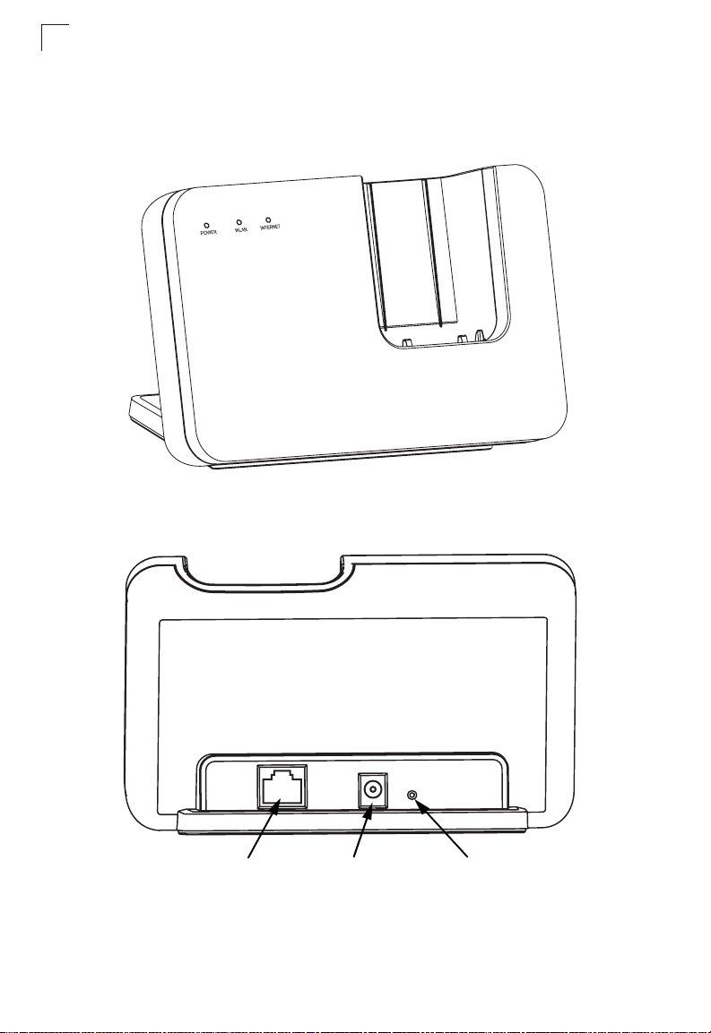
Hardware Description
Front Panel
Back Panel
1-2
Ethernet Port DC-IN Power Socket Reset Button
Page 11
Hardware Description
Wi-Fi Phone Cradle
The SMC Cradle Access Point accepts an SMC Wi-Fi Phone in its cradle for
charging the battery. When the device is powered on, just place the phone in the
cradle and charging starts immediately.
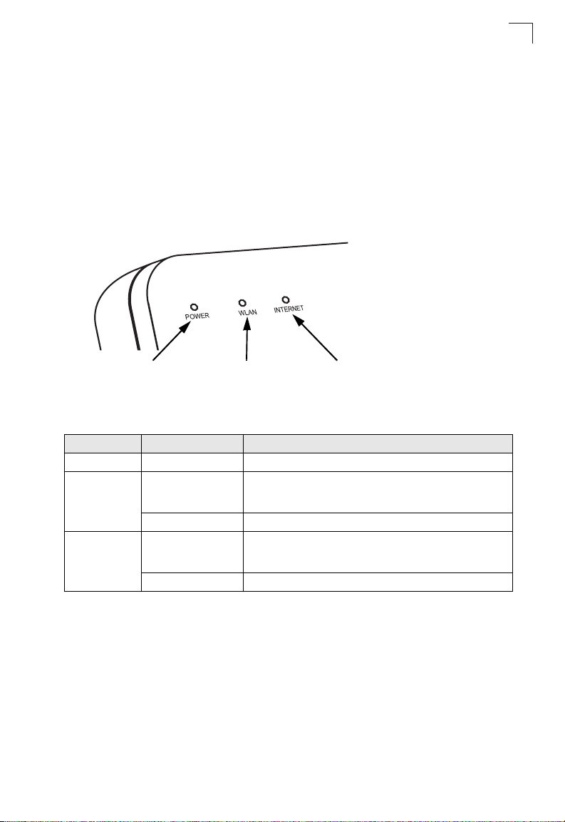
LED Indicators
The access point includes three status LED indicators, as described in the following
figure and table.
1
Power
LED Status Description
POWER On Green Indicates that the system is working normally.
WLAN On Indicates the 802.11g radio is enabled and transmitting or
Off Indicates the 802.11g radio is disabled.
INTERNET On/Flashing Green Indicates a valid link on the Ethernet port and that the access
Off The Ethernet port has no valid link.
802.11g
Wireless
Link/Activity
receiving data through wireless links. The flashing rate is
proportional to network activity.
point is transmitting or receiving data. The flashing rate is
proportional to network activity.
Ethernet
Link/Activity
Ethernet Port
The access point has one 10/100BASE-TX RJ-45 port that can be attached directly
to 10/100BASE-TX LAN segments. Connect this port to the device (cable or ADSL
modem) that provides your Internet access, or to a LAN switch in a network that has
Internet access.
This port supports automatic MDI/MDI-X operation, so you can use straight-through
cables for all network connections to PCs, switches, or hubs.
1-3
Page 12

Introduction
1
Power Socket
The access point does not have a power switch. It is powered on when connected to
the AC power adapter, and the power adapter is connected to a power source. The
power adapter automatically adjusts to any voltage between 100-240 volts at 50 or
60 Hz. No voltage range settings are required.
Reset Button
The Reset button can be used to restart the access point or restore the factory
default configuration. If you press the button for less than 5 seconds, the access
point will restart. If you press and hold down the button for 5 seconds or more, any
configuration changes you may have made are removed and the access point is
restored to its factory default configuration.
1-4
Page 13

Chapter 2: Hardware Installation
To install the SMC Cradle Access Point, follow these steps:
1. Select a Site – Choose a proper place for the access point. In general, the best
location is at the center of your wireless coverage area, within line of sight of all
wireless devices. For optimum performance, consider these points:
• Mount the access point as high as possible above any obstructions in the
coverage area.
• Avoid mounting next to or near building support columns or other obstructions
that may cause reduced signal or null zones in parts of the coverage area.
• Mount away from any signal absorbing or reflecting structures (such as those
containing metal).
• Avoid radio interference by mounting away from other 2.4 GHz devices, such as
other 802.11b or g wireless devices, regular cordless phones, and microwave
ovens.
2. Mount the Access Point – The access point is designed to be mounted on any
horizontal surface, such as a desktop.
3. Connect the Power Cord – Connect the power adapter to the access point,
and plug the power adapter into an AC power outlet.
Warning: Use ONLY the power adapter supplied with the access point.
Otherwise, the product may be damaged.
4. Observe the Indicator LEDs – When you power on the access point verify that
the POWER LED turns on and that the other LED indicators start functioning as
described under “LED Indicators".
5. Connect the Ethernet Cable – The access point can be connected to any 10
or 100 Mbps Ethernet network device, such as a hub or a switch. Connect your
network to the RJ-45 port on the back panel using category 3, 4, or 5 UTP
Ethernet cable. When the access point and the connected device are powered
on, the INTERNET LED should turn on indicating a valid network connection. If
the INTERNET LED fails to turn on, refer to “Troubleshooting".
Note: The RJ-45 port on the access point supports automatic MDI/MDI-X operation, so
you can use straight-through cables for all network connections to PCs, switches,
or hubs.
2-1
Page 14

Hardware Installation
2
2-2
Page 15
Chapter 3: Initial Configuration
The SMC Cradle Access Point offers a user-friendly web-based management
interface for the configuration of all the unit’s features. Any PC with a wired or
wireless connection to the unit can access the management interface using a web
browser, such as Internet Explorer (version 5.0 or above). The initial configuration
steps can be made through the web browser interface using the Setup Wizard.
Connecting to the Web Interface
It is recommended to make the initial changes by connecting to the web
management interface through a wired connection to the access point’s Ethernet
port using the default IP (Internet Protocol) address of 192.168.1.1. Alternatively,
you can connect to the web interface through a wireless connection. Either method
may require changing the IP address settings of the attached PC.
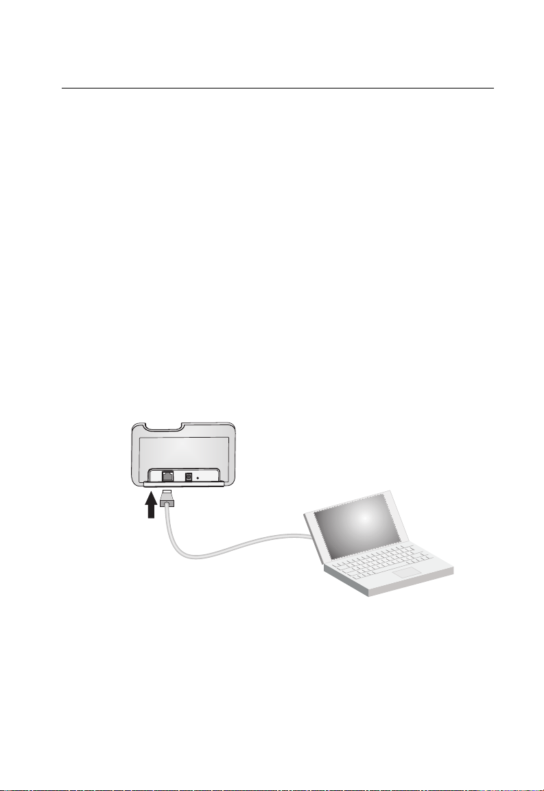
The following procedure shows how to access the web interface from a PC
connected to the access point’s Ethernet port:
1. Place the access point close to the PC that you will use for configuration. It
helps if you can see the front panel LEDs of the access point while working on
your PC.
AP’s Default IP Address 192.168.1.1
PC’s IP Address 192.168.1.x
Direct Ethernet
Cable Connection
Figure 3-1. Connecting to the Web Management Interface
2. Connect the network port of your PC to the access point’s Ethernet port, start
your PC (if it is not already running), connect power to the access point and,
when your PC has finished its start-up sequence, verify that you have a link by
checking the LEDs on the front-panel of the access point.
3. Set your PC’s IP address to be on the same subnet as the access point. The
default IP address of the access point is 192.168.1.1 and the subnet mask is
3-1
Page 16

Initial Configuration
3
255.255.255.0, so the PC and access point are on the same subnet when they
both have addresses that start 192.168.1.x. If the PC and access point are
already on the same subnet, proceed directly to step 4. Otherwise, you must
manually set the PC’s IP address to 192.168.1.x (where “x” can be any number
from 2 to 254). If you are unfamiliar with this process, see “Changing a PC’s IP
Settings” below.
4. Open your web browser and enter the address http://192.168.1.1. If your PC is
properly configured, you will see the login page of your access point. If you do
not see the login page, check your settings and repeat step 3.
5. Proceed to the following sections for information on logging into the web
interface and starting the Setup Wizard.
Management Access Through a Wireless Connection
You can also access the web management interface from a PC using a wireless
connection. Follow these steps:
1. Ensure your PC is equipped with an 802.11g or 802.11b wireless adapter and
has a WLAN utility installed.
2. Set your PC’s IP settings so that it automatically obtains an IP address from the
access point. If you are unfamiliar with this process, see “Changing a PC’s IP
Settings” below.
3. Start your PC's WLAN utility and search for available wireless networks.
4. Find the wireless network named "SMC" and connect to it. (Be sure the access
point is already powered on and the WLAN LED is flashing.)
5. Open your web browser and enter the IP address 192.168.2.1 in the address
bar. The access point login page should display. If you do not see the login
page, check your PC's settings and repeat step 3.
Changing a PC’s IP Settings
To change the IP settings of your PC:
1. On Windows
Connections on the Control Panel window.
2. Right-click the icon for the network connection you want to change, and then
click properties.
3. On the General tab, under This connection uses the following items, select
Internet Protocol (TCP/IP), and then click Properties.
3-2
®
XP, go to Start, then Network Connections. Or, find Network
Page 17

Management Access Through a Wireless Connection
4. In the Internet Protocol (TCP/IP) Properties dialog box, do one of the
following:
a. To set a specific IP address, click Use the following IP address, then type
your intended settings for IP address, Subnet mask, and Default
gateway.
b. To be automatically assigned an IP address, click Obtain an IP address
automatically.
5. Click OK to save the changes and then click OK again to close the Properties
dialog box.
Note: If you are using an operating system other than Windows XP and are unsure how
to change the IP settings, refer to your operating system on-line help or user
documentation.
3
3-3
Page 18
Initial Configuration
3
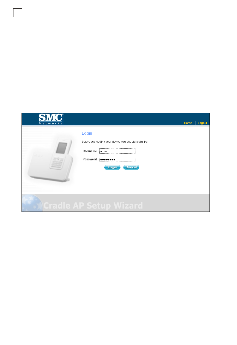
Logging into the Web Interface
In the web browser’s address bar, type the default IP address of http://192.168.1.1
for a wired connection, or http://192.168.2.1 for a wireless connection. The web
browser displays the access point’s login page.
The default Username is “admin” with a default Password of “smcadmin.” Click
LOGIN to access the web management interface.
Note: It is strongly recommended that you change the default user name and password.
If the default values are not changed, the management interface is not protected
and anyone that can connect to the access point may be able to compromise your
network security. For information on changing the user name and password, see
“Administration” on page 4-7.
3-4
Figure 3-2. Login Page
Page 19

Logging into the Web Interface
The home page displays the Main Menu. There are two options available, you can
configure the basic features of the access point using the Setup Wizard’s simple
steps, or you can configure all features in detail using the Advanced Setup menu.
Figure 3-3. Home Page
3
3-5
Page 20

Initial Configuration
3
Using the Setup Wizard
There are only a few basic steps you need to set up the access point and provide a
connection for your Wi-Fi phone and network access for other wireless stations.
The Setup Wizard takes you through configuration procedures for the general
network settings, such as IP configuration, wireless network name (Service Set
Identifier), and wireless security. Follow these steps:
1. Launch the Setup Wizard – Click “Start with Setup Wizard” on the home page.
2. Network Setting – Sets the access point’s IP address assignment method and
configures the local Dynamic Host Configuration Prototcol (DHCP) server and
Network Address Translation (NAT) settings.
Figure 3-4. Setup Wizard - Network Setting
There are three basic methods for configuring the access point’s IP address:
• Dynamic IP — The IP address is assigned automatically from a home
gateway router or other device that has a DHCP server feature.
• PPPoE — The IP address is assigned automatically from an Internet service
provider (ISP) through an ADSL modem using Point-to-Point Protocol over
Ethernet (PPPoE). If your ISP has provided you with a user name and
password, enter these in the corresponding text boxes under PPPoE Setting.
• Static IP — The IP address is assigned manually by the user. This may be
required if your access point is connected to a home gateway router or other
device that does not support a DHCP server.
3-6
Page 21

Using the Setup Wizard
If you select Static IP, enter an appropriate IP address and subnet mask that are
compatible with your existing network. If a management station exists on
another network segment, then you must enter the IP address for a Default
Gateway that can route traffic between these segments. Also enter the IP
address for the Domain Name Server (DNS) to be used for host-name to IP
address resolution.
Figure 3-5. Setup Wizard - DHCP Server and NAT Settings
3. DHCP Server/NAT Setting — This access point includes a DHCP server that
can assign IP addresses to any wireless station or Wi-Fi phone requesting the
service. Addresses are assigned from a common address pool configured on
the access point. You can configure the address pool by specifying start and
end IP addresses.
3
NAT is a standard method of mapping multiple “internal” IP addresses to one
“external” IP address on devices at the edge of a network. For the access point,
the internal (local) IP addresses are the IP addresses assigned to wireless
clients by the DHCP server, and the external IP address is the IP address
assigned to the access point itself. Note that the access point IP address is
always in a different subnet from the DHCP server pool. The access point uses
the NAT IP settings to route traffic from the wireless interface to the Ethernet
network.
Note: When using a wireless client to access the web management interface with the
DHCP server enabled, be sure to change your PC’s IP settings to “Obtain an IP
address automatically” and then use the configured Gateway IP address (default:
192.168.2.1) in your web browser..
Wireless VAP 1 Setting – Sets the wireless Service Set Identifier (SSID) and
4.
wireless security encryption key for the VAP 1 network. An SSID is a
recognizable text name that identifies a wireless network. Wireless clients that
want to connect to a network through an access point must set their SSIDs to
match that of the access point.
This access point supports two independent wireless networks (SSID
interfaces) using the same radio. These SSID interfaces, or Virtual Access
3-7
Page 22

Initial Configuration
3
Points (VAPs), enable wireless traffic to be separated for different user groups
within the same service area. Wireless clients within the service area connect to
what appears to be different access points, but is in fact the same physical unit.
For each SSID interface (or VAP) different security settings can be applied. This
allows you to set one SSID for public use and keep the other SSID private, or
restrict one SSID for Wi-Fi phones only and use the other for PC wiress data.
Figure 3-6. Setup Wizard - Setting the VAP 1 SSID and Security
Enter the SSID, or wireless network name, which all wireless stations must use
to associate with the access point. The SSID is case sensitive and can consist
of up to 32 alphanumeric characters (Default: SMC AP1).
The access point offers two wireless security options; Wired Equivalent Privacy
(WEP) or Wi-Fi Protected Access Pre-shared Key (WPA / WPA2-PSK). Select
the security you want to use and enter the appropriate encryption key, or select
“none” for no security.
• WEP Key — Enter 10 hexadecimal digits (0 to 9 and A to F) or 5
alphanumeric characters for 64 bit keys, 26 hexadecimal digits or 13
alphanumeric characters for 128 bit keys, and 32 hexadecimal digits or 16
alphanumeric characters for 152 bit keys.
• WPA / WPA2-PSK Key — Enter as an easy-to-remember form of letters and
numbers. The key must be from 8 to 63 characters, which can include
spaces.
Note: All wireless devices must be configured with the same WEP or WPA / WPA2-PSK
Key values to communicate with the access point.
3-8
Page 23

Using the Setup Wizard
5. Wireless VAP 2 Setting – Sets the wireless Service Set Identifier (SSID) and
wireless security encryption key for the VAP 2 wireless network.
Figure 3-7. Setup Wizard - Setting the VAP 2 SSID and Security
Enter the SSID, or wireless network name, which all wireless stations must use
to associate with the access point. The SSID is case sensitive and can consist
of up to 32 alphanumeric characters (Default: SMC AP2).
3
The access point offers two wireless security options; Wired Equivalent Privacy
(WEP) or Wi-Fi Protected Access Pre-shared Key (WPA / WPA2-PSK). Select
the security you want to use and enter the appropriate encryption key, or select
“none” for no security.
• WEP Key — Enter 10 hexadecimal digits (0 to 9 and A to F) or 5
alphanumeric characters for 64 bit keys, 26 hexadecimal digits or 13
alphanumeric characters for 128 bit keys, and 32 hexadecimal digits or 16
alphanumeric characters for 152 bit keys.
• WPA / WPA2-PSK Key — Enter as an easy-to-remember form of letters and
numbers. The key must be from 8 to 63 characters, which can include
spaces.
Note: All wireless devices must be configured with the same WEP or WPA /
Key values to communicate with the access point.
6.
Click Finish.
WPA2-PSK
3-9
Page 24

Initial Configuration
3
Figure 3-8. Setup Wizard - Finish
7. Click the Continue button to make other configuration changes before restarting
the access point, or click the Reboot button to restart immediately.
Note that the access point will start using any configured new IP settings, which
must be used to access the web management interface.
3-10
Page 25

Chapter 4: System Configuration
The access point’s basic settings can be configured using the Setup Wizard, as
described in the previous chapter, “Initial Configuration.” However, for some
installations, you may need to configure specific settings that are not available in the
Setup Wizard. The Advanced Setup menu provides access to all the unit’s settings
for complete control of the access point’s features.
To access the Advanced Setup menus, follow these steps:
1. Use your web browser to connect to the management interface using the
default IP address of 192.168.1.1 or the IP address set through the Wizard.
2. Log into the access point management interface by entering the user name
“admin” and password “smcadmin” (the default), and click “LOGIN.”
3. When the home page displays, click on Advanced Setup. The following page
displays.
Figure 4-1. Advanced Setup
The information in this chapter is organized to reflect the structure of the web
management screens for easy reference. However, it is recommended that you first
change the user name and password to control access to the management
interface. For details, see “Administration” on page 4-7.
4-1
Page 26

System Configuration
4
The Advanced Setup pages include the options in the table below. For details on
configuration for each feature, see the corresponding page number.
Table 4-1. Configuration Options
Menu Description Page
Information
System Displays a summary of access point settings 4-3
Clients Displays information on stations associated to the access
Network Displays DHCP client, server, NAT, and PPPoE settings 4-5
Event Log Displays the system message log 4-6
System
Administration Configures the password for management
Reboot System Restarts the system and resets configuration settings to
Wireless VAP 1, 2
Basic Enables the VAP interface and sets the SSID 4-9
Channel Sets the radio channel 4-10
WEP Configures WEP security 4-11
WPA / WPA2-PSK Configures WPA-PSK security 4-12
Network
DHCP Client Enables DHCP client or manually sets an IP address 4-14
DHCP Server/NAT Enables DHCP server and configures NAT settings 4-15
PPPoE Configures PPPoE settings 4-16
Time & Log
SNTP Sets the system clock using SNTP 4-17
Update
Upgrade via the Web
Page
Upgrade via a Remote
Server
point
access
factory defaults
Upgrades system software from a local file
Upgrades system software from a file on an FTP or TFTP
server
4-4
4-7
4-8
4-18
4-19
4-2
Page 27

Information
Information
The system information pages display details on the current configuration and status
of the access point, including associated wireless stations and event log messages.
System
The system information page displays basic system configuration settings, as well
as the settings for each wireless interface. The displayed settings are for status
information only and are not configurable on this page.
4
Figure 4-2. System Information
The displayed items on this page can be described as follows:
Cradle AP System Configuration – Displays basic system configuration settings:
• System Up Time – Length of time since the access point was powered on.
• MAC Address – The physical layer address for the access point’s Ethernet port.
• IP Address – The IP address configured on the access point.
4-3
Page 28

System Configuration
4
• IP Default Gateway – The IP address of the gateway router between the access
point and management stations that exist on other network segments.
• HTTP Server – The status of the web management server.
• HTTP Server Port – The TCP port used by the web management server.
• Version – The version number of the current access point software.
Wireless VAP 1/2 Configuration – The AP Wireless Configuration table displays
the wireless interface settings listed below.
•Status – The status of the Configuration.
• SSID – The service set identifier for this wireless group.
• Channel – The radio channel through which the access point communicates with
wireless clients.
• Encryption – The key size used for data encryption.
• Authentication Type – Shows if open system or shared key authentication is
used.
• Multicast Cipher – The encryption used for broadcast and multicast data.
Client
The client information page displays details on wireless devices currently associated
to the access point. The displayed settings are for status information only and are
not configurable on this page.
Figure 4-3. Client Information
The displayed items on this page can be described as follows:
• Station Address – The MAC address of the wireless client.
• Authenticated – Shows if the client has been authenticated. The two basic
methods of authentication supported for 802.11 wireless networks are “open
system” and “shared key.” Open-system authentication accepts any client
attempting to connect to the access point without verifying its identity. The
shared-key approach uses Wired Equivalent Privacy (WEP) to verify client identity
by distributing a shared key to clients before attempting authentication.
4-4
Page 29

Information
• Associated – Shows if the client has been successfully associated with the access
point. Clients can associate with the access point only after authentication has
completed.
• Encryption – Indicates if encryption is being used by the client; either Enabled or
Disabled.
• Cipher – Indicates the encryption cipher capability being advertised by the client;
WEP, TKIP, AES, or None.
• SSID -- The VAP interface that the client is associated with.
• RSSI -- The received signal strength of the client. The greater the RSSI value, the
stronger the wireless signal from the client.
Network
The network information page displays the current Dynamic Host Configuration
Protocol (DHCP) client, DHCP server, and Point-to-Point Protocol over Ethernet
(PPPoE) status. The displayed settings are for status information only and are not
configurable on this page.
4
Figure 4-4. Network Information
The displayed items on this page can be described as follows:
• DHCP Client Setting – Enables the access point to automatically obtain an IP
address from a DHCP server. When disabled, or if a response is not received from
the DHCP server, the access point uses the configured static IP settings on the
Network > DHCP Client page. (Default: Enabled)
• DHCP Server/NAT Setting – Enables or disables the DHCP server on the access
point. The access point DHCP server can assign IP addresses to any wireless
client requesting the service. Addresses are assigned to clients from a common
address pool configured on the Network > DHCP Server/NAT page.
(Default: Enabled)
• PPPoE Setting – Enables a connection to an Internet service provider using
PPPoE. The PPPoE access user name and password can be set on the
Network > PPPoE page. (Default: Disabled)
4-5
Page 30

System Configuration
4
Event Log
The Event Log page displays system messages generated during system operation.
The logged messages can serve as a valuable tool for isolating access point and
network problems.
Figure 4-5. Event Log
The Event Log page displays the last 128 messages logged in chronological order, from
the newest to the oldest. Log messages saved in the access point’s memory are erased
when the device is rebooted.
4-6
Page 31

System Settings
System Settings
The system settings pages allow you to change the management access password
and restart the access point.
Administration
Management access to the access point is controlled through a single user name
and password.
To protect access to the management interface, you need to change the default use
name and password as soon as possible. If the user name and password are not
changed, then anyone having access to the access point may be able to
compromise the access point and network security.
Note: If you forget your user name or password, you can press the reset button on the
back of the access point for more than five seconds to reset to the factory
defaults.
4
Figure 4-6. Administration Password
The displayed items on this page can be described as follows:
• Username – The name of the user. The default is "admin." The user name can be
changed. (Length: 0-16 characters, case sensitive)
• New Password – The password for management access. (Length: 0-16
characters, case sensitive)
• Confirm New Password – Enter the password again for verification.
• Country – Sets the country in which the access point is being used. Some
countries allow the user to set the access point so that it conforms to the local
wireless regulations. This setting ensures that the access point uses only the radio
channels and transmit power levels permitted for that region. It is the user’s
responsibility to set the correct country (the default is “NO_COUNTRY_SET”).
Once a country has been set, the Country setting is no longer displayed on this
page. To change the Country setting, you must reset the access point to its factory
default configuration.
4-7
Page 32

System Configuration
4
Units intended for use in other countries, such as the United States, are
pre-configured to use only the appropriate channels and the user cannot change
the Country setting. For units shipped to these countries, the Country setting is not
displayed on this web page.
Reboot System
The Reboot System page allows you to restart the access point software and restore
factory default settings.
Figure 4-7. Reboot System
The displayed items on this page can be described as follows:
• Restore Factory Settings – Click the Restore button to reset the configuration
settings for the access point to the factory defaults and reboot the system. Note
that all user configured information will be lost. You will have to use the default IP
address to re-gain management access to the access point.
• Reboot Access Point – Click the Reboot button to reboot the system.
Note: If you have upgraded the system software, then you must reboot the access point
to implement the new code.
4-8
Page 33

Wireless VAP Settings
Wireless VAP Settings
The Wireless VAP 1 Setting (Default: Enabled) and Wireless VAP 2 Setting
(Default: Disabled) pages include configuration options for radio signal
characteristics and wireless security features on the access point.
The following sections apply to both Wireless VAP 1 Setting and Wireless VAP 2
Setting pages.
Basic
The Basic Setting page allows you to enable the VAP radio interface and define the
Service Set IDentifier (SSID).
The access point includes an IEEE 802.11g radio for wireless communications. The
IEEE 802.11g standard operates within the 2.4 GHz band at up to 54 Mbps. Note
that because the IEEE 802.11g standard is an extension of the IEEE 802.11b
standard, it allows clients with 802.11b wireless network cards to associate to an
802.11g access point.
The SSID is a recognizable text string that identifies the wireless network service
provided by the VAP interface. Wireless clients that want to connect to the network
must set their SSIDs to match that of the VAP interface.
4
Figure 4-8. Basic Wireless Settings
The displayed items on this page can be described as follows:
• Radio Status – Enables radio communications for the VAP interface.
(Default: VAP 1 - Enabled, VAP 2 - Disabled)
• Radio Mode – Defines the radio mode for the VAP interface. (Default: b+g mix)
- b only: Both 802.11b and 802.11g clients can communicate with the access
point, but 802.11g clients can only transfer data at 802.11b standard rates (up
to 11 Mbps).
- b + g mix: Both 802.11b and 802.11g clients can communicate with the access
point (up to 54 Mbps).
4-9
Page 34

System Configuration
4
- g only: Only 802.11g clients can communicate with the access point (up to 54
Mbps). The g-only mode provides better wireless network performance, but
802.11b clients cannot connect to the access point.
• SSID – The name of the wireless network service provided by the VAP. Clients that
want to connect to the network must set their SSID to the same as that of the VAP
interface. (Defaults: VAP 1 - “SMC AP1,” VAP 2 “SMC AP2”; Range: 1-32
characters)
Channel Setting
The access point uses one radio channel in the 2.4 GHz band to communicate with its
clients. The radio channel may be set manually by the user or automatically by the
system, which selects the channel with the least radio interference.
Note: If you experience poor performance, you may be encountering interference from
another wireless device. Try changing the channel, as this may eliminate
interference and increase performance. Channels 1, 6, and 11, as the three
non-overlapping channels in the 2.4 GHz band, are preferred.
Figure 4-9. Wireless Channel Setting
The displayed items on this page can be described as follows:
• Auto Channel Selection – Enables the access point to automatically select an
interference-free radio channel. (Default: Enabled)
• Radio Channel – The radio channel that the access point uses to communicate
with wireless clients. When multiple access points are deployed in the same area,
set the channel on neighboring access points at least five channels apart to avoid
interference with each other. For example, you can deploy up to three access
points in the same area using channels 1, 6, 11. Note that wireless clients
automatically set the channel to the same as that used by the access point to which
it is linked. (Range: 1-11)
4-10
Page 35

Wireless VAP Settings
WEP Security
The access point is configured by default as an “open system,” which broadcasts a
beacon signal including the configured SSID. Wireless clients with a configured
SSID of “any” can read the SSID from the beacon and automatically set their SSID
to allow immediate connection to the access point. To secure the wireless network,
you have to implement user authentication and wireless data encryption.
Wired Equivalent Privacy (WEP) provides a basic level of security, preventing
unauthorized access to the network and encrypting data transmitted between
wireless clients and the access point. WEP uses static shared keys (fixed-length
hexadecimal or alphanumeric strings) that are manually distributed to all clients that
want to use the network.
4
Figure 4-10. WEP Wireless Security
The displayed items on this page can be described as follows:
• WEP Status – Enables the access point to use WEP shared keys. If enabled, you
must configure at least one key for the VAP interface and all its clients.
• Key Type – Select the preferred method of entering WEP encryption keys on the
access point.
- Hexadecimal: Enter keys as hexadecimal digits (0 to 9 and A to F).
- Alphanumeric: Enter keys as alphanumeric characters.
• Setting Key – Sets WEP key values for one or two keys. At least one key must be
specified. Each WEP key has an index number. The selected key is used for
authentication and encryption on the VAP interface.
Enter key values that match the key type and length settings. Select 64 Bit, 128 Bit,
or 152 Bit key length. Note that the same size of encryption key must be supported
on all wireless clients. (Default: 64 Bit)
- 64 Bit: Enter keys as 5 alphanumeric characters or 10 hexadecimal digits.
4-11
Page 36

System Configuration
4
- 128 Bit: Enter keys as 13 alphanumeric characters or 26 hexadecimal digits.
- 152 Bit: Enter keys as 16 alphanumeric characters or 32 hexadecimal digits.
Note: Key index and type must match that configured on all clients.
WPA-PSK Security
Wi-Fi Protected Access (WPA) employs a combination of technologies to provide an
enhanced security solution for wireless networks. The WPA Pre-shared Key
(WPA-PSK) mode for small networks uses a common password phrase that must be
manually distributed to all clients that want to connect to the network.
WPA2 is a futher security enhancement that includes the now ratified IEEE 802.11i
wireless security standard. Both WPA and WPA2 provide very robust security
through the support of the Advanced Encryption Standard (AES) and Temporal Key
Integrity Protocol (TKIP) encryption ciphers.
Note: The computationally intensive operations of AES encryption requires hardware
support on client devices. Before implementing AES in the network, be sure that
wireless client hardware is AES or WPA2 compliant.
Figure 4-11. WPA-PSK Wireless Security
The displayed items on this page can be described as follows:
• WPA-PSK Status – Enables WPA-PSK or WPA2-PSK security on the VAP
interface. When enabled, WEP clients are not supported. (Default: Disabled).
• Authentication – Selects the wireless security mechanism for the network.
- WPA-PSK – Use pre-shared key authentication for WPA-compliant clients.
- WPA2-PSK – Use pre-shared key authentication for WPA2-compliant clients.
- WPA Mix Mode – Use pre-shared key authentication for WPA- and
WPA2-compliant clients when they coexist in the same network.
• Key Cipher Mode – Selects the encryption cipher to use for multicast and unicast
data traffic:
- Auto – Uses TKIP for the multicast cipher and TKIP or AES for the unicast cipher
depending on the capability of associated clients.
- AES – Uses AES keys for both multicast and unicast encryption.
- TKIP – Uses TKIP keys for both multicast and unicast encryption.
4-12
Page 37

Wireless VAP Settings
• WPA-PSK Key – Enter a key as an easy-to-remember form of letters and
numbers. The key must be from 8 to 63 characters, which can include spaces. All
wireless clients must be configured with the same key to communicate with the
VAP interface.
4
4-13
Page 38

System Configuration
4
Network Settings
The access point supports DHCP client, DHCP server and Network Address
Translation (NAT). Point-to-Point Protocol over Ethernet (PPPoE) is also supported
for users that have an IP address assigned automatically from an Internet service
provider (ISP) through an ADSL modem.
DHCP Client
Configuring the access point with an IP address enables you to manage the access
point from any PC in the attached network. A number of access point features
depend on IP addressing to operate.
Note: You can connect to the web browser interface to access IP addressing only if the
access point already has an IP address that is reachable through your network.
By default, the access point is configured with the IP address 192.168.1.1, with the
DHCP client enabled.
Figure 4-12. DHCP Client Settings
The displayed items on this page can be described as follows:
• DHCP Client Setting – Enables the access point to automatically obtain an IP
address from a DHCP server. If a response is not received from the DHCP server,
the access point uses the fixed IP settings as configured on this page. When set to
disabled, a static IP address can be manually configured.
• Static IP Address – The IP address of the access point. Valid IP addresses
consist of four decimal numbers, 0 to 255, separated by periods.
• Subnet Mask – The mask that identifies the host address bits used for routing to
specific subnets.
• Default Gateway – The default gateway is the IP address of the router for the
access point, which is used if the requested destination address is not on the local
subnet. If you have management stations located on another subnet, type the IP
4-14
Page 39

Network Settings
address of the default gateway router in the text field provided. Otherwise, leave
the address as (192.168.1.254).
• DNS IP Address – The IP address of a Domain Name Server on the network. A
DNS maps numerical IP addresses to domain names and can be used to identify
network hosts by familiar names instead of the IP addresses.
If you have a DNS server located on the local network, type the IP address in the
text field provided. Otherwise, leave the address as all zeros (0.0.0.0).
DHCP Server/NAT
The access point includes a Dynamic Host Configuration Protocol (DHCP) server
that can assign temporary IP addresses to wireless clients requesting the service.
Addresses are assigned to clients from a common address pool configured on the
access point. Configure an address pool by specifying start and end IP addresses.
Be sure not to include the access point's IP address in the address pool range.
Network Address Translation (NAT) is a standard method of mapping multiple
"internal" IP addresses to one "external" IP address on devices at the edge of a
network. For the access point, the internal (local) IP addresses are the IP addresses
assigned to wireless clients by the DHCP server, and the external IP address is the
IP address assigned to the Ethernet port. When enabled, the access point's wireless
interface uses the NAT IP settings to access the Ethernet network.
Note: When the DHCP server is enabled, NAT is also enabled.
4
Figure 4-13. DHCP Server/NAT Settings
The displayed items on this page can be described as follows:
• DHCP Server/NAT Setting – Enables or disables the DHCP server and NAT on
the access point. (Default: Enabled)
4-15
Page 40

System Configuration
4
• Start/End IP Address – Specifies the start/end IP address of a range that the
DHCP server can assign to DHCP clients. You can specify a single address or an
address range.
• Gateway – The IP address of the gateway router for the access point, which is
used if the requested destination address is not on the local subnet.
• DNS IP Address – The IP address of a Domain Name Server on the network. A
DNS maps numerical IP addresses to domain names and can be used to identify
network hosts by familiar names instead of the IP addresses.
Note: With DHCP Server/NAT enabled, a wireless PC needs to use the configured
Gateway IP address (Default: 192.168.2.1) to access the web management
interface. With DHCP Server/NAT disabled, both wired and wireless PCs can use
the DHCP client setting (Default: 192.168.1.1).
PPPoE
Many Internet service providers (ISPs) use the Point-to-Point Protocol over Ethernet
(PPPoE) to automatically assign an IP address to users with a DSL modem. The
PPPoE page provides the settings needed for this service.
Figure 4-14. PPPoE Settings
The displayed items on this page can be described as follows:
• PPPoE Setting — Enables the access point IP address to be assigned
automatically from an Internet service provider (ISP) through an ADSL modem
using PPPoE.
• Username — If your ISP has provided you with a PPPoE user name, enter it in the
corresponding text box.
• Password — If your ISP has provided you with a PPPoE password, enter it in the
corresponding text box.
4-16
Page 41

Time and Log
Time and Log
Simple Network Time Protocol (SNTP) allows the access point to set its internal
clock based on periodic updates from a time server (SNTP or NTP). Maintaining an
accurate time on the access point enables all system log messages to be stamped
with the correct time and date. If the clock is not set, the access point only records
the time from the factory default set at the last bootup.
The access point acts as an SNTP client, which periodically sends time
synchronization requests to a specific time server. SNTP uses Coordinated
Universal Time (or UTC, formerly Greenwich Mean Time, or GMT) based on the
time at the Earth’s prime meridian, zero degrees longitude. To display the time
corresponding to your local time, you must also indicate the number of hours your
time zone is located before or after UTC/GMT.
4
Figure 4-15. SNTP Settings
The displayed items on this page can be described as follows:
• SNTP Server Setting — Configures the access point to operate as an SNTP client.
When enabled, the time server IP address must be specified.
• Primary Server: The IP address of an SNTP or NTP time server that the access
point attempts to poll for a time update.
• Time Zone — Sets the number of hours your local time zone is located before or
after UTC/GMT. (Default: GMT+00)
• Daylight Saving — The access point provides a way to automatically adjust the
system clock for Daylight Savings Time changes. To use this feature you must
define the month and date to begin and to end the change from standard time.
During this period the system clock is set back by one hour.
4-17
Page 42

System Configuration
4
Updating Firmware
You can upgrade new access point software from a local file on the management
workstation, or from an FTP or TFTP server.
After upgrading to new software, you must reboot the access point to implement the
new code. Until a reboot occurs, the access point will continue to run the software it
was using before the upgrade started.
Note: The software file can be downloaded from a PC using a wired or wireless
connection. However, it is strongly recommended to use a wired connection for
downloading new software.
Upgrade via the Web Page
This web page allows you to download a new software code file from the local web
management station to the access point using HTTP.
Figure 4-16. Web Page Upgrade
The displayed items on this page can be described as follows:
• New Firmware File — Specifies the name of the code file on the local web
management station. You can use the Browse button to locate the image file locally
on the management station.
• Start Upgrade — Starts the download process. Be sure to allow enough time for
the download to complete before rebooting the access point.
4-18
Page 43

Updating Firmware
Upgrade via a Remote Server
This web page allows you to download a new software code file from a remote
server to the access point using FTP or TFTP.
When using an FTP or TFTP server, be sure to first obtain the IP address of the
server and note the correct file path where the access point software is stored. If
upgrading from an FTP server, also make sure that you have a user account
configured on the server with a user name and password.
Figure 4-17. Remote Server Upgrade
The displayed items on this page can be described as follows:
• Remote File — Specifies a software code file download from a remote FTP or
TFTP server.
• New firmware file — Specifies the name of the code file on the server. A path on
the server can be specified using “/” in the destination file name, providing the path
already exists. Other than to indicate a path, the file name must not contain any
slashes (\ or /), the leading letter cannot be a period (.), and the maximum length
for file names on the FTP/TFTP server is 255 characters or 32 characters for files
on the access point. (Valid characters: A-Z, a-z, 0-9, “.”, “-”, “_”)
• IP Address — IP address or host name of the FTP or TFTP server.
• Username — The user ID used for login to an FTP server.
• Password — The password used for login to an FTP server.
• Start Upgrade — Starts the download process. Be sure to allow enough time for
the download to complete before rebooting the access point.
4
4-19
Page 44

System Configuration
4
4-20
Page 45

Appendix A: Troubleshooting
Diagnosing Access Point Indicators
Troubleshooting Chart
Symptom Action
POWER LED is Off
WLAN LED is Off
INTERNET LED is Off • Verify that the access point and attached device are powered on.
Wireless Connection Problems
Check the following items before you contact local Technical Support.
1. If wireless clients cannot access the network, check the following:
• Be sure the access point and the wireless clients are configured with the same
Service Set ID (SSID).
• If authentication or encryption are enabled, ensure that the wireless clients are
properly configured with the appropriate authentication or encryption keys.
2. If the access point cannot be configured using a web browser:
• Be sure to have configured the access point with a valid IP address, subnet
mask and default gateway.
• If you are connecting to the access point through the wired Ethernet interface,
check the network cabling between the management station and the access
point. If you are connecting to access point from a wireless client, ensure that
you have a valid connection to the access point.
3. If you forgot or lost the password:
• Set the access point to its default configuration by pressing the reset button
on the back panel for 5 seconds or more. Connect to the web management
interface using the default IP address 192.168.1.1. Then use the default user
name and password “smcadmin” to access the management interface.
• AC power adapter may be disconnected. Check connections between
the access point, the power adapter, and the wall outlet.
• The access point’s radio has been disabled through it’s web
management interface. Access the management interface using a
web browser to enable the WLAN radio.
• Be sure the cable is plugged into both the access point and
corresponding device.
• Verify that the proper cable type is used and its leng th does not exceed
specified limits.
• Check the cable connections for possible defects. Replace the
defective cable if necessary.
A-1
Page 46

Troubleshooting
A
4. If all other recovery measure fail, and the access point is still not functioning
properly, take any of these steps:
• Reset the access point’s hardware using the web interface or through a power
reset.
• Reset the access point to its default configuration by pressing the reset button
on the back panel for 5 seconds or more. Connect to the web management
interface using the default IP address 192.168.1.1, then use the default user
name “admin” and password “smcadmin.”
A-2
Page 47

Appendix B: Cables and Pinouts
Twisted-Pair Cable Assignments
For 10/100BASE-TX connections, a twisted-pair cable must have two pairs of wires.
Each wire pair is identified by two different colors. For example, one wire might be
green and the other, green with white stripes. Also, an RJ-45 connector must be
attached to both ends of the cable.
Caution: Each wire pair must be attached to the RJ-45 connectors in a specific
orientation. (See “Straight-Through Wiring” on page B-2 and “Crossover
Wiring” on page B-2 for an explanation.)
Caution: DO NOT plug a phone jack connector into the RJ-45 port. Use only twisted-pair
The following figure illustrates how the pins on the RJ-45 connector are numbered.
Be sure to hold the connectors in the same orientation when attaching the wires to
the pins.
cables with RJ-45 connectors that conform with FCC standards.
8
1
8
1
10/100BASE-TX Pin Assignments
Use unshielded twisted-pair (UTP) or shielded twisted-pair (STP) cable for RJ-45
connections: 100-ohm Category 3 or better cable for 10 Mbps connections, or
100-ohm Category 5 or better cable for 100 Mbps connections. Also be sure
length of any twisted-pair connection does not exceed 100 meters (328 feet).
The RJ-45 port on the access point supports automatic MDI/MDI-X operation, so
you can use straight-through or crossover cables for all network connections to PCs,
switches, or hubs. In straight-through cable, pins 1, 2, 3, and 6, at one end of the
cable, are connected straight through to pins 1, 2, 3, and 6 at the other end.
Pin MDI Signal Name MDI-X Signal Name
1 Transmit Data plus (TD+) Receive Data plus (RD+)
2 Transmit Data minus (TD-) Receive Data minus (RD-)
3 Receive Data plus (RD+) Transmit Data plus (TD+)
6 Receive Data minus (RD-) Transmit Data minus (TD-)
4,5,7,8 Not used Not used
Note: The “+” and “-” signs represent the polarity of the wires that make up each wire pair.
that the
B-1
Page 48

Cables and Pinouts
B
Straight-Through Wiring
If the twisted-pair cable is to join two ports and only one of the ports has an internal
crossover (MDI-X), the two pairs of wires must be straight-through.
EIA/TIA 568B RJ-45 WiringStandard
10/100BASE-TX Straight-through Cable
White/Orange Stripe
Orange
End A
1
2
3
4
5
6
7
8
White/Green Stripe
Blue
White/Blue Stripe
Green
White/Brown Stripe
Brown
1
2
3
4
5
6
7
8
End B
Crossover Wiring
If the twisted-pair cable is to join two ports and either both ports are labeled with an
“X” (MDI-X) or neither port is labeled with an “X” (MDI), a crossover must be
implemented in the wiring.
EIA/TIA 568B RJ-45 WiringStandard
10/100BASE-TX Crossover Cable
White/Orange Stripe
Orange
End A
1
2
3
4
5
6
7
8
White/Green Stripe
Blue
White/Blue Stripe
Green
White/Brown Stripe
Brown
1
2
3
4
5
6
7
8
End B
B-2
Page 49

Appendix C: Specifications
Maximum Channels
FCC/IC: 1-11
ETSI: 1-13
France: 10-13
MKK: 1-14
Ta i w a n : 1 - 11
Maximum Clients
32 per VAP interface
Data Rate
802.11g: 6, 9, 12, 18, 24, 36, 48, 54 Mbps per channel
802.11b: 1, 2, 5.5, 11 Mbps per channel
Modulation Type
802.11g: CCK, BPSK, QPSK, OFDM
802.11b: CCK, BPSK, QPSK
Network Configuration
Infrastructure
Operating Frequency
2.4 ~ 2.4835 GHz (US, Canada, ETSI)
2.4 ~ 2.497 GHz (Japan)
2.400 ~ 2.4835 GHz (Taiwan)
Wireless Output Power
802.11b: 19 dBm (typical)
802.11g: 18 dBm @ 6 Mbps, 15 dBm @ 54 Mbps
Wireless Receive Sensitivity
802.11b: -90 dBm @ 1 Mbps, -84 dBm @ 11 Mbps
802.11g: -86 dBm @ 6 Mbps, -68 dBm @ 54 Mbps
AC Power Adapter
Input: 100-240 VAC, 50-60 Hz
Output: 5 VDC, 2 A
Unit Power Supply
DC Input: 5 VDC, 2 A maximum
Power Consumption: 6.5 W maximum
Physical Size
14.7 x 9.2 x 7.7 cm (5.79 x 3.6 x 3.03 in)
Weight
170 g (6 oz)
LED Indicators
POWER (Power), INTERNET (Ethernet Link/Activity), WLAN (Wireless Link/Activity)
C-1
Page 50

Specifications
C
Network Management
Web-browser
Temperature
Operating: 0 to 40 °C (32 to 104 °F)
Storage: -20 to 70 °C (-4 to 158 °F)
Humidity
15% to 95% (non-condensing)
Compliances
FCC Part 15B Class B
VCCI Class B
EN 55022 Class B
EN 55024
EN 50385
EN61000-3-2
EN61000-3-3
Radio Signal Certification
FCC Part 15C 15.247, 15.207 (2.4 GHz)
EN 300-328
EN 301 489-1
EN 301 489-17
ARIB STD-T66
ARIB STD-33
RSS-210
DGT
Safety
EN 60950-1
IEC 60950-1 (CB)
Standards
IEEE 802.3-2005 10BASE-T, 100BASE-TX
IEEE 802.11b, g
Wi-Fi 11b/g, WPA, WPA2, WMM
C-2
Page 51

Glossary
10BASE-T
IEEE 802.3 specification for 10 Mbps Ethernet over two pairs of Category 3 or better
UTP cable.
100BASE-TX
IEEE 802.3u specification for 100 Mbps Fast Ethernet over two pairs of Category 5
or better UTP cable.
Access Point
An internetworking device that seamlessly connects wired and wireless networks.
Access points attached to a wired network, support the creation of multiple radio
cells that enable roaming throughout a facility.
Ad Hoc
A group of computers connected as an independent wireless network, without an
access point.
Advanced Encryption Standard (AES)
An encryption algorithm that implements symmetric key cryptography. AES provides
very strong encryption using a completely different ciphering algorithm to TKIP and
WEP.
Authentication
The process to verify the identity of a client requesting network access. IEEE 802.11
specifies two forms of authentication: open system and shared key.
Backbone
The core infrastructure of a network. The portion of the network that transports
information from one central location to another central location where it is unloaded
onto a local system.
Beacon
A signal periodically transmitted from the access point that is used to identify the
service set, and to maintain contact with wireless clients.
Broadcast Key
Broadcast keys are sent to stations using dynamic keying. Dynamic broadcast key
rotation is often used to allow the access point to generate a random group key and
periodically update all key-management capable wireless clients.
Glossary-1
Page 52

Glossary
Dynamic Host Configuration Protocol (DHCP)
Provides a framework for passing configuration information to hosts on a TCP/IP
network. DHCP is based on the Bootstrap Protocol (BOOTP), adding the capability
of automatic allocation of reusable network addresses and additional configuration
options.
Encryption
Data passing between the access point and clients can use encryption to protect
from interception and evesdropping.
Ethernet
A popular local area data communications network, which accepts transmission
from computers and terminals.
File Transfer Protocol (FTP)
A TCP/IP protocol used for file transfer.
Hypertext Transfer Protocol (HTTP)
HTTP is a standard used to transmit and receive all data over the World Wide Web.
IEEE 802.11b
A wireless standard that supports wireless communications in the 2.4 GHz band
using Direct Sequence Spread Spectrum (DSSS). The standard provides for data
rates of 1, 2, 5.5, and 11 Mbps.
IEEE 802.11g
A wireless standard that supports wireless communications in the 2.4 GHz band
using using Orthogonal Frequency Division Multiplexing (OFDM). The standard
provides for data rates of 6, 9, 12, 18, 24, 36, 48, 54 Mbps. IEEE 802.11g is also
backward compatible with IEEE 802.11b.
Infrastructure
An integrated wireless and wired LAN is called an infrastructure configuration.
Local Area Network (LAN)
A group of interconnected computer and support devices.
MAC Address
The physical layer address used to uniquely identify network nodes.
Network Time Protocol (NTP)
NTP provides the mechanisms to synchronize time across the network. The time
servers operate in a hierarchical-master-slave configuration in order to synchronize
local clocks within the subnet and to national time standards via wire or radio.
Glossary-2
Page 53

Glossary
Open System
A security option which broadcasts a beacon signal including the access point’s
configured SSID. Wireless clients can read the SSID from the beacon, and
automatically reset their SSID to allow immediate connection to the nearest access
point.
Orthogonal Frequency Division Multiplexing (ODFM)
OFDM/ allows multiple users to transmit in an allocated band by dividing the
bandwidth into many narrow bandwidth carriers.
Service Set Identifier (SSID)
An identifier that is attached to packets sent over the wireless LAN and functions as
a password for joining a particular radio cell; i.e., Basic Service Set (BSS).
Session Key
Session keys are unique to each client, and are used to authenticate a client
connection, and correlate traffic passing between a specific client and the access
point.
Shared Key
A shared key can be used to authenticate each client attached to a wireless network.
Shared Key authentication must be used along with the 802.11 Wireless Equivalent
Privacy algorithm.
Simple Network Time Protocol (SNTP)
SNTP allows a device to set its internal clock based on periodic updates from a
Network Time Protocol (NTP) server. Updates can be requested from a specific NTP
server, or can be received via broadcasts sent by NTP servers.
Temporal Key Integrity Protocol (TKIP)
A data encryption method designed as a replacement for WEP. TKIP avoids the
problems of WEP static keys by dynamically changing data encryption keys.
Trivial File Transfer Protocol (TFTP)
A TCP/IP protocol commonly used for software downloads.
Wi-Fi Protected Access
WPA employs 802.1X as its basic framework for user authentication and dynamic
key management to provide an enhanced security solution for 802.11 wireless
networks.
Glossary-3
Page 54

Glossary
Wired Equivalent Privacy (WEP)
WEP is based on the use of security keys and the popular RC4 encryption
algorithm. Wireless devices without a valid WEP key will be excluded from network
traffic.
WPA Pre-shared Key (WPA-PSK)
WPA-PSK can be used for small office networks with a limited number of users that
may not need a high level of security. WPA-PSK provides a simple security
implementation that uses just a pre-shared password for network access.
Glossary-4
Page 55

Index
A
authentication
4-11
type
C
cable
assignments
channels, maximum C-1
clients, maximum C-1
configuration settings, saving or
restoring
configuration, initial setup 3-1
B-1
4-8
D
data rate, options C-1
DHCP 4-14
server 4-15
DNS 4-15, 4-16
Domain Name Server See DNS
downloading software
4-18
E
Ethernet
2-1
cable
port 1-3
F
factory defaults
restoring
firmware
upgrading
4-8
4-18
I
IEEE 802.11g
configuring interface
radio channel 4-10
initial setup 3-1
installation
mounting
IP address
configuring
2-1
3-6, 4-14
4-9
M
mounting the access point 2-1
multicast cipher 4-12
O
open system 4-11
operating frequency C-1
P
package checklist 1-1
PoE
specifications
power connection 2-1
C-1
R
radio channel
802.11g interface
reset 4-8
reset button 4-8
resetting the access point 4-8
restarting the system 4-8
4-10
G
gateway address 4-14, 4-16
S
security, options 4-11
SNTP 4-17
enabling client 4-17
server 4-17
Index-1
Page 56

Index
software
displaying version
downloading 4-18
specifications C-1
SSID
configuring
system clock, setting 4-17
system software, downloading from
4-18
server
4-3, 4-18
3-7, 3-9
T
troubleshooting A-1
U
upgrading software 4-18
user name, manager 4-7
user password 4-7
W
WEP
configuring
WPA
pre-shared key
4-11
4-13
Index-2
Page 57

Page 58

Model Number: SMCDPCR-AP
Pub. Number: 149100037100E, E112006-EK-R01
 Loading...