


TigerChassis 10/100/1000
14-Slot Multilayer Chassis Switch
◆ IP routing with RIP and OSPF support
◆ Optional blades include 10BASE-T/100BASE-TX, 100BASE-FX, 1000BASE-SX/LX, 10/
100/1000BASE-T, GBIC
◆ 12 slots available for media expansion
◆ 24 Gbps switch fabric for non-blocking switching performance
◆ Security features to prevent intruder access and ensure a safe network
environment
◆ Full support for IEEE 802.1Q VLANs with GVRP
◆ QoS support for IEEE 802.1p priority
◆ IGMP and DVMRP multicast support
◆ Optional redundant power, fan, and switch fabric failover support
◆ Manageable via console, web, SNMP/RMON
◆ Supports CIDR, multinetting
Installation and Maintenance Guide
SMC9712G


TigerChassis 10/100/1000
Installation and Maintenance Guide
From SMC’s Chassis line of feature-rich workgroup LAN solutions
38 Tesla
Irvine, CA 92618
Phone: (949) 679-8000
January 2002
Pub. # 150200008900A R01

Information furnished by SMC Networks, Inc. (SMC) is believed to be accurate and reliable. However, no responsibility is assumed by SMC for its
use, nor for any infringements of patents or other rights of third parties which may result from its use. No license is granted by implication or
otherwise under any patent or patent rights of SMC. SMC reserves the right to change specifications at any time without notice.
Copyright © 2002 by
SMC Networks, Inc.
38 Tesla
Irvine, CA 92618
All rights reserved. Printed in Taiwan
Trademarks:
SMC is a registered trademark; and TigerChassis is a trademark of SMC Networks, Inc. Other product and company names are trademarks or registered trademarks
of their respective holders.

L
IMITED
Limited Warranty Statement: SMC Networks, Inc. (“SMC”) warrants its products to be free from defects in workmanship and materials, under
normal use and service, for the applicable warranty term. All SMC products carry a standard 90-day limited warranty from the date of purchase
from SMC or its Authorized Reseller. SMC may, at its own discretion, repair or replace any product not operating as warranted with a similar or
functionally equivalent product, during the applicable warranty term. SMC will endeavor to repair or replace any product returned under warranty
within 30 days of receipt of the product.
The standard limited warranty can be upgraded to a Limited Lifetime* warranty by registering new products within 30 days of purchase from
SMC or its Authorized Reseller. Registration can be accomplished via the enclosed product registration card or online via the SMC web site.
Failure to register will not affect the standard limited warranty. The Limited Lifetime warranty covers a product during the Life of that Product,
which is defined as the period of time during which the product is an “Active” SMC product. A product is considered to be “Active” while it is
listed on the current SMC price list. As new technologies emerge, older technologies become obsolete and SMC will, at its discretion, replace an
older product in its product line with one that incorporates these newer technologies. At that point, the obsolete product is discontinued and is no
longer an “Active” SMC product. A list of discontinued products with their respective dates of discontinuance can be found at:
http://www.smc.com/index.cfm?action=customer_service_warranty.
All products that are replaced become the property of SMC. Replacement products may be either new or reconditioned. Any replaced or repaired
product carries either a 30-day limited warranty or the remainder of the initial warranty, whichever is longer. SMC is not responsible for any
custom software or firmware, configuration information, or memory data of Customer contained in, stored on, or integrated with any products
returned to SMC pursuant to any warranty. Products returned to SMC should have any customer-installed accessory or add-on components, such
as expansion modules, removed prior to returning the product for replacement. SMC is not responsible for these items if they are returned with
the product.
Customers must contact SMC for a Return Material Authorization number prior to returning any product to SMC. Proof of purchase may be
required. Any product returned to SMC without a valid Return Material Authorization (RMA) number clearly marked on the outside of the
package will be returned to customers at customer’s expense. For warranty claims within North America, please call our toll-free customer
support number at (800) 762-4968. Customers are responsible for all shipping charges from their facility to SMC. SMC is responsible for return
shipping charges from SMC to customer.
WARRANTIES EXCLUSIVE: IF AN SMC PRODUCT DOES NOT OPERATE AS WARRANTED ABOVE, CUSTOMER’S SOLE
REMEDY SHALL BE REPAIR OR REPLACEMENT OF THE PRODUCT IN QUESTION, AT SMC’S OPTION. THE FOREGOING
WARRANTIES AND REMEDIES ARE EXCLUSIVE AND ARE IN LIEU OF ALL OTHER WARRANTIES OR CONDITIONS,
EXPRESS OR IMPLIED, EITHER IN FACT OR BY OPERATION OF LAW, STATUTORY OR OTHERWISE, INCLUDING
WARRANTIES OR CONDITIONS OF MERCHANTABILITY AND FITNESS FOR A PARTICULAR PURPOSE. SMC NEITHER
ASSUMES NOR AUTHORIZES ANY OTHER PERSON TO ASSUME FOR IT ANY OTHER LIABILITY IN CONNECTION WITH
THE SALE, INSTALLATION, MAINTENANCE OR USE OF ITS PRODUCTS. SMC SHALL NOT BE LIABLE UNDER THIS
WARRANTY IF ITS TESTING AND EXAMINATION DISCLOSE THE ALLEGED DEFECT IN THE PRODUCT DOES NOT EXIST
OR WAS CAUSED BY CUSTOMER’S OR ANY THIRD PERSON’S MISUSE, NEGLECT, IMPROPER INSTALLATION OR TESTING,
UNAUTHORIZED ATTEMPTS TO REPAIR, OR ANY OTHER CAUSE BEYOND THE RANGE OF THE INTENDED USE, OR BY
ACCIDENT, FIRE, LIGHTNING, OR OTHER HAZARD.
LIMITATION OF LIABILITY: IN NO EVENT, WHETHER BASED IN CONTRACT OR TORT (INCLUDING NEGLIGENCE),
SHALL SMC BE LIABLE FOR INCIDENTAL, CONSEQUENTIAL, INDIRECT, SPECIAL, OR PUNITIVE DAMAGES OF ANY KIND,
OR FOR LOSS OF REVENUE, LOSS OF BUSINESS, OR OTHER FINANCIAL LOSS ARISING OUT OF OR IN CONNECTION
WITH THE SALE, INSTALLATION, MAINTENANCE, USE, PERFORMANCE, FAILURE, OR INTERRUPTION OF ITS PRODUCTS,
EVEN IF SMC OR ITS AUTHORIZED RESELLER HAS BEEN ADVISED OF THE POSSIBILITY OF SUCH DAMAGES.
SOME STATES DO NOT ALLOW THE EXCLUSION OF IMPLIED WARRANTIES OR THE LIMITATION OF INCIDENTAL OR
CONSEQUENTIAL DAMAGES FOR CONSUMER PRODUCTS, SO THE ABOVE LIMITATIONS AND EXCLUSIONS MAY NOT
APPLY TO YOU. THIS WARRANTY GIVES YOU SPECIFIC LEGAL RIGHTS, WHICH MAY VARY FROM STATE TO STATE.
NOTHING IN THIS WARRANTY SHALL BE TAKEN TO AFFECT YOUR STATUTORY RIGHTS.
* SMC will provide warranty service for one year following discontinuance from the active SMC price list. Under the limited lifetime warranty,
internal and external power supplies, fans, and cables are covered by a standard one-year warranty from date of purchase.
W
ARRANTY
SMC Networks, Inc.
38 Tesla
Irvine, CA 92618
i

L
IMITED WARRANTY
ii

CONTENTS
ABOUT THIS GUIDE
Audience Definition 11
Conventions 11
Related Documentation 12
1 SETTING UP YOUR SMC9712G
2 OVERVIEW OF THE SMC9712G
Product Overview 15
Physical Description 15
Minimum Requirements for Normal Operation 16
Module Slots in the Chassis 16
Building a System 17
Servicing a System 17
Switch Backplane Architecture 18
3 SITE REQUIREMENTS AND PRODUCT SPECIFICATIONS
Physical Specifications 19
Environmental Specifications 20
Ventilation Requirements 20
Location Requirements 20
Precautionary Guidelines 21
Power Requirements 22
Power Cords 22
Safety Information 22
Laser Warning 23
FDA Class 1 Laser Device 23
LED Warning 23
Regulatory Compliance 24
4 SMC9712G CHASSIS
Overview 25
Preinstallation Guidelines 26
Safety Precautions 26
Rack Installation Guidelines 27
Chassis PreInstallation Guidelines 27

Cable Management Device Preinstallation Guidelines 27
Rack Installation 28
Table or Shelf Installation 30
Installing the Cable Management Device 31
5 SMC9712G POWER SUPPLIES
Power Supply Features 33
Normal Operating Requirements 34
Power Supply Slot Covers 34
AC and DC LEDs 35
No ON/OFF Switch 35
Power Cords 35
Autosensing Capability 35
How Two Supplies Operate 35
Maintenance 35
If Failure Occurs 35
Hot Swap 35
Installing a Power Supply 36
Removing a Power Supply 38
Troubleshooting a Power Supply 39
Diagnosing Switch Indicators 39
Intermittent Operation 39
Power Supply Failure 39
6 SMC9712G FAN TRAYS
Fan Tray Description 41
Normal Operation 42
Maintenance 42
If Failure Occurs 42
Hot Swap 42
Removing a Fan Tray 43
Installing a Fan Tray 44
Troubleshooting a Fan Tray 46
7 NETWORK MANAGEMENT MODULES AND INTERFACE MODULES
Network Management Module Overview 48
Network Functions 48
Management Functions 48
High Availability Operation 51
Installation 52
The Relationship Between Two Management Modules 52
The Failover Process 52
Connectivity Rules 52
Interface Module Overview 53
Feature Configuration Process 53
Traffic Handling 53

Hot Swap 53
Fast Ethernet Interface Modules 53
8-port 10/100BASE-TX Fast Ethernet Module 53
8-port 100BASE-FX Fast Ethernet Module 54
Gigabit Ethernet Interface Modules 57
1000BASE-SX Gigabit Ethernet Modules 57
1000BASE-T Gigabit Ethernet Modules 57
GBIC Gigabit Ethernet Modules 58
Installing a Module 61
Safety Precautions 61
ESD Safety Information 62
Handling Precautions 62
Installation Prerequisites 62
Slot Restrictions 62
Installation and Removal Consequences 63
Module Installation Procedure 64
Removing a Module 66
GBIC Transceivers 67
Compatible Transceivers 67
1000BASE-LX GBIC Transceiver 67
1000BASE-SX GBIC Transceiver 67
Attaching and Removing GBIC Transceivers 68
Troubleshooting Modules 69
Interface Modules 69
Network Management Modules 69
A TECHNICAL SUPPORT
Online Technical Services 71
World Wide Web Site 71
Support from Your Network Supplier 71
Support from SMC 71
GLOSSARY
INDEX


ABOUT THIS GUIDE
This SMC9712G Installation and Maintenance Guide provides a description of
SMC9712G components, installation and removal procedures, site requirements,
and important safety information for SMC9712G components.
Audience Definition This guide is intended for network administrators who are responsible for
installing and managing the network hardware and who are considered to be
trained service personnel. This guide assumes that the network administrator has a
working knowledge of local area network (LAN) operations, but it does not
assume prior knowledge of SMC9712G high performance networking equipment.
Furthermore, this guide assumes that the network administrator has obtained the
appropriate technical training and experience to perform tasks in service access
areas of network equipment, to be aware of electrical hazards or other hazards
that exist in performing these tasks, and to take steps that minimize the danger to
themselves or other persons.
Conventions Table 1 and Table 2 list conventions that are used throughout this guide.
Table 1 Notice Icons
Icon Notice Type Description
Information note Information that describes important features or instructions
Caution Information that alerts you to potential loss of data or potential
damage to an application, system, or device
Warning Information that alerts you to potential personal injury
Table 2 Text Conventions
Convention Description
Words in italics Italics are used to:
■ Emphasize a point.
■ Denote a new term at the place where it is defined in the text.

12 ABOUT THIS GUIDE
Related Documentation The SMC9712G documentation set includes the following documents:
■ SMC9712G Installation and Maintenance Guide (this guide)
■ SMC9712G Key Information Guide
■ SMC9712G Software Configuration Guide
■ SMC9712G Release Notes
To read a brief description of each document, to understand how each document
is distributed, or to learn how to order additional paper copies or download
electronic copies, see the SMC9712G Key Information Guide, which is included in
the shipping box of every item in the SMC9712G product set.

1
SETTING UP YOUR SMC9712G
To install your SMC9712G safely and efficiently so that you can connect it to your
network, follow these tasks:
1 Read Chapter 2 in this guide for a quick review of basic facts about the Switch.
2 Ensure that your installation environment meets the site requirements described in
Chapter 3.
3 Unpack and inspect the SMC9712G components for visible damage, if you have
not already done so.
For unpacking procedures and information on how to proceed if damage exists,
see the SMC9712G Key Information Guide.
See Chapter 5 for the installation procedure.
4 Install the chassis.
5 (Optional) Install a second power supply (for redundancy) into the chassis before
you install it on a table, shelf, or in a rack.
See Chapter 4 for the installation procedure.
SMC recommends that you do not connect the SMC9712G to a power source
until all components are installed. This way, you can focus your attention on all
module LEDs simultaneously.
6 (If required) Install Fast Ethernet and Gigabit Ethernet Interface Modules.
If you need to install additional modules, see Chapter 7 for the information about
their physical attributes and module installation procedure.
All chassis ship from the manufacturing center with a Network Management
Module (NMM) preinstalled, thus you do not have to install one. However, you can
install a second (redundant) NMM to provide standby management support.
At your option, you may connect network cabling to your SMC9712G interface
modules prior to powering on the Switch. However, once the Switch is powered
on, be aware that features such as the Spanning Tree Protocol’s root bridge
election process may affect your network operations. If you are unfamiliar with the
SMC9712G, SMC recommends that you power up the Switch without cabling
attached so that you can first spend a few minutes studying the management
interface.
7 Power on the system by connecting the power cables to the sockets on the
SMC9712G power supplies and then to the dedicated power outlets.
There is no ON/OFF button on the SMC9712G. The system is powered on as long
as the mains power source is connected to the Switch. If you need to cycle power
to the SMC9712G, you can either unplug and replug the power cord, or you can
do it through a command on the SMC9712G management interface.

14 CHAPTER 1: SETTING UP YOUR SMC9712G
If you installed a second, redundant power supply, SMC recommends that you
connect it to a dedicated power source.
After power is supplied to the SMC9712G, power supplies begin operating, fans
start rotating, all modules begin power-on verification processes and
self-diagnostic processes, and the NMM begins its software boot cycle. The
module LEDs will flash in different colors and sequences during this time.
8 Wait for the chassis to finish its start-up sequence of diagnostic tests.
This could take up to five minutes (approximately).
For information about module LEDs, see Table 5, Table 6, Table 11, and Table 13 in
Chapter 7.
The SMC9712G is not ready for operation until its initialization processes finish.
This process may last up to 5 minutes.
If no problems exist at the completion of the module initialization process, you
should see the following:
■ All four fans are rotating continuously.
■ The AC and DC LEDs on each installed power supply are lighted.
■ The Power LED on the NMM module is Green.
■ The Diagnostic LED on all modules is Green.
■ The Port Link and Mode LEDs on all interface modules remain off until you
attach cabling and functioning network links are created.
If a Module Diagnostic LED is off after the diagnostics run, that module has failed.
If you observe error conditions with the following hardware components, see the
referenced chapter:
■ power supplies, see “Troubleshooting a Power Supply” in Chapter 5.
■ fans, see “Troubleshooting a Fan Tray” in Chapter 6.
■ modules, see“Troubleshooting Modules” in Chapter 7.
9 To view or modify the default software configuration, use a standard null modem
cable to connect a terminal or PC with terminal emulation software (such as
®
HyperTerm that is included with Windows
) to the console port on the NMM.
At this point, the menu-driven command line interface (CLI) that is built into the
software becomes visible to you.
See the SMC9712G Software Configuration Guide to view or modify the default
settings in the software as well as to learn about other management interface
options.
10 When you are ready to join the SMC9712G to the rest of your network, attach
GBIC transceivers (if applicable) and network cabling to the ports on the interface
modules.

OVERVIEW OF THE SMC9712G
2
This chapter provides an introduction to the design of the SMC9712G. The topics
in this chapter include:
■ Product Overview
■ Switch Backplane Architecture
Product Overview The SMC9712G is a feature-rich, 14-slot, modular routing switch that can be
configured with up to 24 Gigabit Ethernet ports or up to 96 Fast Ethernet ports
with currently available modules. The SMC9712G currently supports redundant
power supplies, redundant Network Management Modules, and a variety of Fast
Ethernet and Gigabit Ethernet Interface Modules. Combining the speed and low
cost of a Layer 2 switch with Layer 3 routing capabilities, the SMC9712G currently
routes the IP protocol and offers many other advanced features to provide the
high performance that you need to aggregate wiring closets in your network.
Physical Description A SMC9712G chassis can contain:
■ Two fa n tray s.
Each fan tray contains two fans (four fans total). Both fan trays are required for
normal operation.
■ Two 300 Watt AC power supplies
Only one power supply is required for normal operation. If installed, a second
power supply provides load-sharing and redundancy.
■ Two Network Management Modules (NMMs)
Only one NMM is required for normal operation. If the NMM is removed from a
powered up chassis that is functioning in a network, chassis operations will
cease. However, if a backup NMM is installed in the chassis, and the primary
NMM is removed or fails, the backup NMM will take over operations.
The NMM has two elements: a central Network, which manages the layer 3
routing functions of the system such as routing table updates and layer 3
configuration changes, and the management of the system, which includes
SNMP, command line interface (CLI), and Web client activities.
■ Up to Twelve Fast Ethernet or Gigabit Ethernet Interface Modules
You install the number and type of interface modules that are appropriate to
your cabling infrastructure and bandwidth requirements. When the source and
destination ports are located on the same interface module, the interface
module performs local switching. If the destination port resides on a different
interface module, the interface module forwards the packet to the NMM.
16 CHAPTER 2: OVERVIEW OF THE SMC9712G
Minimum Requirements
for Normal Operation
Module Slots in the
Chassis
The following minimum components are required for normal operation of the
SMC9712G:
■ Two fan trays (four fans total)
■ One 300 Watt AC power supply
■ One Network Management Module (NMM) operating with system software
■ The number and type of interface modules that are appropriate for your
network connectivity needs
■ Blank faceplates that cover all empty module slots and the second power
supply bay (if a second power supply is not installed).
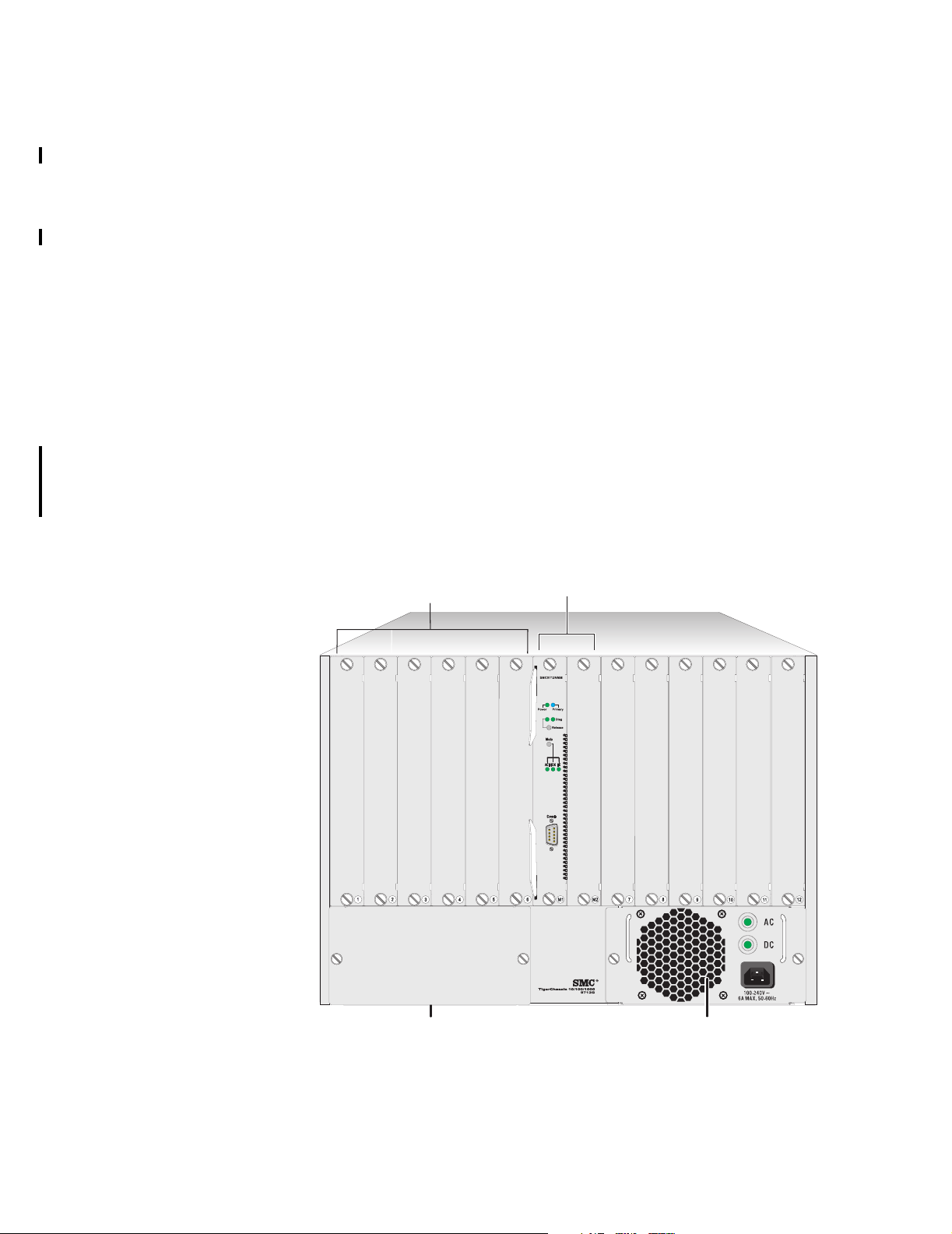
You insert modules vertically into the chassis slots so that the slot number shows
through a hole in the module faceplate. As shown in Figure 1, the slots for
interface modules are numbered from left to right, starting with number 1 and
continuing to 12. The two center slots are numbered M1 and M2 because they
exist solely to contain Network Management Modules (NMMs). An NMM can be
placed in either of these slots.
Figure 1 Front View of a SMC9712G Chassis Without Interface Modules Installed
Interface
module slots
Management
module slots
Powe r
supply
(in slot 1)
Powe r
supply
slot 2
Product Overview 17
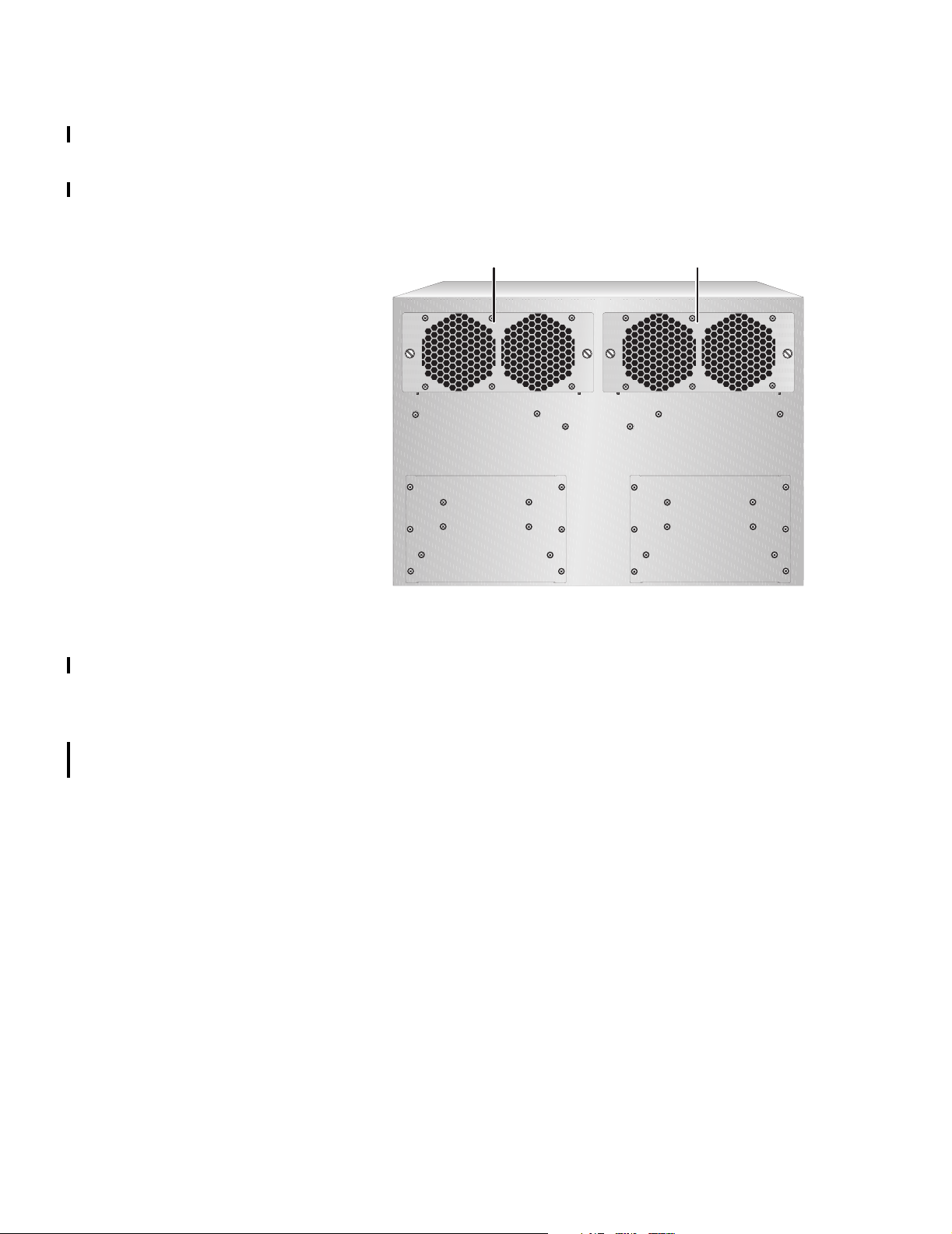
Figure 2 shows the rear view of a standard SMC9712G chassis in the minimum
configuration.
Figure 2 Rear View of a standard SMC9712G Chassis
Fan tray
(in slot 1)
Fan tray
(in slot 2)
Building a System You can build a complete system from component items that are ordered
separately.
Servicing a System For service spares purposes, all component items such as fan trays, power supplies,
and modules can be purchased separately at any time. Check with your network
supplier to see if they stock spare components, provide service, or resell SMC
service agreements.
18 CHAPTER 2: OVERVIEW OF THE SMC9712G
Switch Backplane Architecture
Gigabit
Data
Traces
UART
Control
Traces
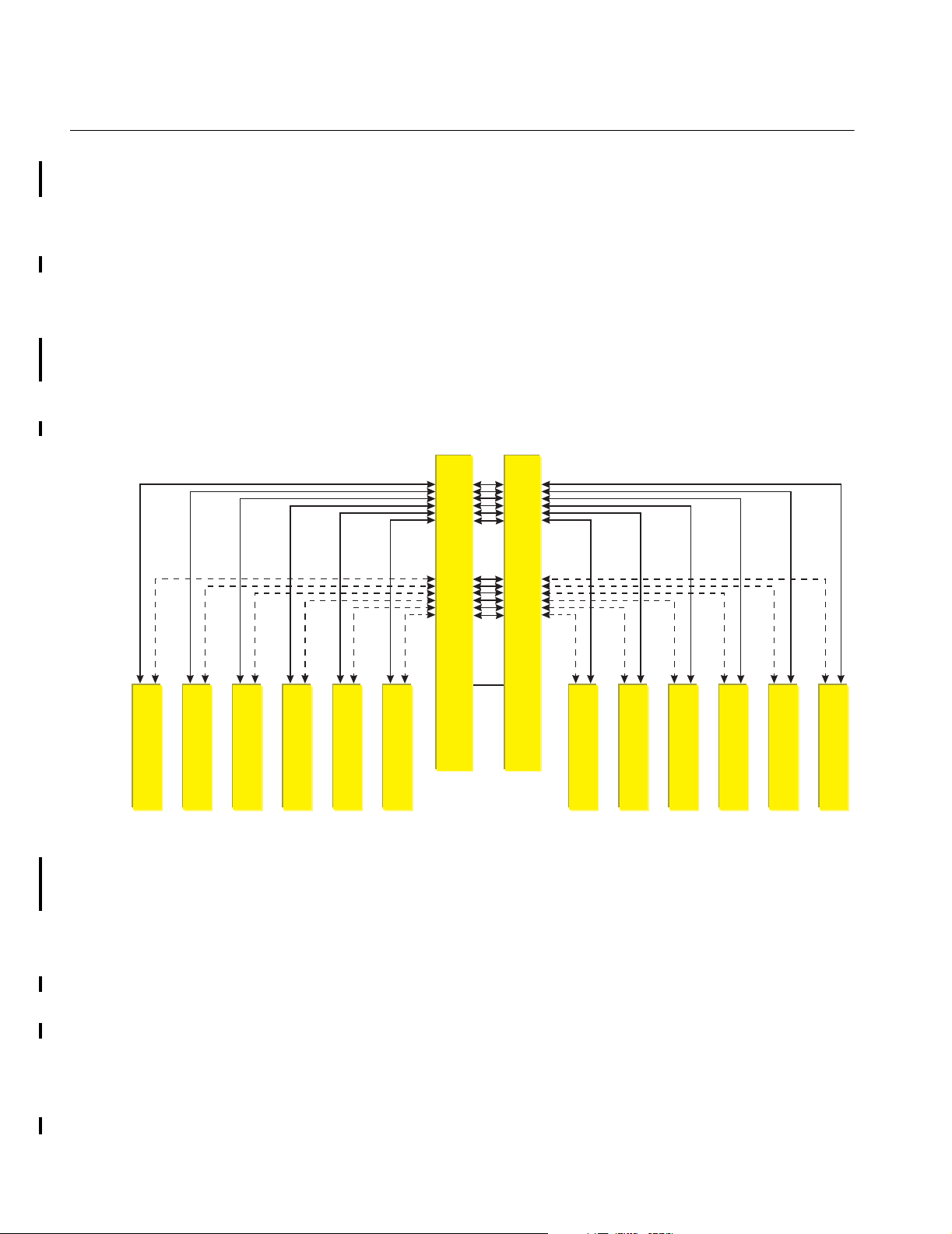
A star-wired scheme of traces inside the chassis, which is called the backplane, is
used to connect each interface module slot to the Network Management Module
(NMM) slots. A module, fan tray, or power supply connects to the backplane when
it is inserted into a slot and its connectors engage the connectors that are inside
the chassis.
As shown in Figure 3, the SMC9712G backplane design offers:
■ 12 Gbps of non-blocking bandwidth capacity
■ Passive design, meaning that there are no active components that can fail
■ Support for dual, redundant Network Management Modules (NMMs)
■ Support for system communication between the NMM and interface modules
for control signals, detection, and other management activities.
Figure 3 Backplane Architecture of the SMC9712G
Swithc Fabric & Management Slot M1
Swithc Fabric & Management Slot M2
SCI
Interface Slot 1
Interface Slot 2
Interface Slot 3
Interface Slot 4
Interface Slot 5
Interface Slot 6
Interface Slot 7
Interface Slot 8
Interface Slot 9
Interface Slot 10
Interface Slot 11
Interface Slot 12
The backplane connector on each module provides easy access to all the services
from the SMC9712G backplane:
■ a data channel for network traffic between the NMM and interface modules
■ a control channel that passes signals for module detection
■ module diagnostics
■ LED operation between the NMM and interface modules
■ a Serial Communication Interface (SCI) communications channel that operates
between two NMMs (if installed) to keep their configurations synchronized
Traffic between ports on the same interface module does not enter the backplane;
that is, the interface modules provide layer 2 and layer 3 switching when the
packet’s destination is a locally attached node. Interface modules send packets
that have non-local destination addresses across the backplane to the NMM which
then switches the packets to the appropriate interface module.

SITE REQUIREMENTS AND PRODUCT
3
PECIFICATIONS
S
This chapter describes the site requirements and product specifications for your
SMC9712G. The major sections are titled as follows:
■ Physical Specifications
■ Environmental Specifications
■ Ventilation Requirements
■ Location Requirements
■ Power Requirements
■ Safety Information
■ Regulatory Compliance
Physical Specifications The physical specifications for the SMC9712G chassis are shown in Table 1.
Tabl e 1 Chassis Physical Specifications
Height
Width
Depth
Weight
Mounting
Network
Interfaces
Management
Access Ports
31.06 cm 12.22 inches (5 Rack Units)
48.3 cm
43.94 cm
29.77 cm 11.72 inches
12.42 kg
20.62 kg
Tabletop, shelf, or standard 19-inch rack
10/100BASE-TX, 100BASE-FX, 1000BASE-SX, 1000BASE-T, GBIC
Any Ethernet port on the interface modules
RS-232 (DB-9) serial port on the Network Management Module
19 inches (including rack-mount flanges)
17.3 inches (not including rack-mount flanges)
27.38 pounds (chassis, backplane, power supply, fans)
45.46 pounds (fully loaded)
20 CHAPTER 3: SITE REQUIREMENTS AND PRODUCT SPECIFICATIONS
Environmental Specifications
Ventilation Requirements
The site for the SMC9712G should meet the environmental requirements shown in
Tab le 2:
Tab le 2 Environmental Specifications
Operating temperature
Operating humidity 10% to 90%, noncondensing
Storage temperature -40 °C to 66 °C
Storage humidity 10% to 90%, noncondensing
1
Switch operating temperature is the temperature of the environment in which the switch is installed.
2
Ambient air is room air (more specifically, the air drawn into the switch by installed fans to cool
installed switch components).
1
0 °C to 50 °C ambient
(32 °F to 122 °F)
(-40 °F to 151 °F)
2
The chassis operates with two fan trays. Each fan tray contains two fans. These
fans pull ambient air into the chassis from vents in the module faceplates and
expel hot air through vents in the back of the fan tray.
Although the fan trays provide the majority of the cooling, the power supplies also
contain fans. Each power supply pulls in ambient air through side vents in the
adjacent chassis wall and expels hot air through its vents in the back.
If a power supply overheats, it shuts itself off.
Location Requirements
To ensure that adequate ventilation exists for the SMC9712G:
■ Maintain at least 7 cm (2.76 in.) between the sides of the chassis and the
nearest wall or other vertical surface.
■ Maintain at least 8 cm (3 in.) between the front of the chassis and another
vertical surface (such as a rack door).
■ Maintain at least 91.4 cm (36 in.) at the back of the chassis.
CAUTION: Operate a SMC9712G chassis with all four fans running. If one fan in a
fan tray fails, replace the fan tray as soon as possible.
Install the SMC9712G in an area that meets the following location requirements:
■ The surface on which you want to place the SMC9712G chassis is level.
■ The power source is within approximately 2 meters (6.6 feet) of the location
where you plan to install the SMC9712G.
■ Each of the power supplies is connected to its own dedicated circuit. Do not
connect the power supplies to a single power strip.
■ There is a sufficient amount of space on each side of the SMC9712G chassis to
accommodate any cables along the side of the chassis.
■ There is at least 91.4 cm (36 in.) at the back of the chassis to service power
supplies and fans.
■ If the chassis is the first device in your rack, then mount it about 10.2 cm (4 in.)
above the floor.

Location Requirements 21
■ The following list shows the amount of rack space that is needed to install a
SMC9712G chassis in a Telco rack or a Metric rack:
■ Height — 31.06 cm / 12.15 in.
The height of the chassis, allowing for some extension beyond the location
of the upper and lower unit dividing lines.
■ Telco Rack Unit — 7.2 RU
The unit of measure is 1 Rack Unit (1.75 in. or 4.45 cm).
■ Metric Rack Unit — 14.4 SU
The unit of measure is 1 System Unit (25 millimeters).
■ Front clearance — 8 cm / 3 in.
This is the recommended minimum space required between the front of the
chassis and another vertical surface (such as a rack door). Your cabling may
require that you leave the rack door open.
Precautionary
Guidelines
■ Safety regulations stipulate that the table, shelf, or rack on which the
SMC9712G rests can support at least 61.8 kg (136.5 lb), which is three times
the weight of a fully loaded SMC9712G chassis.
■ To reduce the possibility of personal injury or serious damage to the chassis, use
at least two people to install the chassis. This is especially important for rack
installations, because you must hold the chassis in place while you secure it to
the rack.
■ If you are installing the SMC9712G in a rack, first ensure that the rack is
installed properly according to the manufacturer’s instructions, which may
include steps such as:
■ Ground the rack in accordance with the rack manufacturer’s instructions.
■ Bolt the rack to the floor.
■ Make certain that the rack is properly aligned and squared. Use a framing
tool to ensure that the rack is squared.
■ Use the following guidelines to tighten screws to Torque Specification:
■ Module faceplate screws — 1.3 in/lb (inch-pounds)
■ Power supplies and fan trays to the chassis — 1.3 in/lb
■ #10 screws for holding the chassis onto a rack — 22-25 in/lb
To ensure that you tighten screws to Torque Specification, use a torque
screwdriver.
22 CHAPTER 3: SITE REQUIREMENTS AND PRODUCT SPECIFICATIONS
Power Requirements This section outlines the power requirements for the SMC9712G 300-watt AC
power supply (Model Number SMC9712P). Table 3 lists power specifications for
the chassis.
Tab le 3 SMC9712G Chassis Power Specifications
Total power consumption
Output voltage
Input voltage range
Inrush current
Input frequency
300 watts, 1023 BTU/hour
+5 V @ 53A,
+12 V @ 3A
United States — 100 to 120 VAC
International — 200 to 240 VAC
6 A
50-60 Hz
The power supplies are autosensing; that is, a power supply can automatically
sense the type of input voltage to which it is being connected at the electrical
outlet.
If a power supply overheats, it shuts itself off.
Power Cords One power cord per power supply is required. If you have two power supplies
installed in the chassis, SMC recommends that you connect them to separate,
dedicated power outlets. The power cord that you require depends on your
country location. The correct power cord should be in your chassis shipping box.
If you do not have the correct power cord, contact your supplier.
Safety Information This section lists warning notices to read before you install the SMC9712G and its
components.
WARNING: The SMC9712G chassis and its components must be installed,
maintained, or replaced only by trained service personnel. This guide assumes that
the network administrator has a working knowledge of local area network (LAN)
operations. Furthermore, this guide assumes that the network administrator has
obtained appropriate technical training and experience to perform tasks in service
access areas of network equipment, to be aware of electrical hazards that exist in
performing these tasks, and to take steps that minimize the danger to themselves
or other persons. If you have questions on installation tasks, contact your network
supplier or SMC technical support. For contact information, see Appendix A.
WARNING: To maintain proper cooling in the chassis and maintain safety
compliance, make certain that blank faceplates cover any empty module slots or
power supply slots.
WARNING: Hazardous energy levels exist inside of the Switch. Do not place hands
or objects into the switch or touch components on an inserted module.
WARNING: Safety regulations state that the selected table, shelf, or rack must be
able to support at least three times the weight of a fully loaded Switch. A fully
loaded SMC9712G chassis weighs approximately 20.6 kg (45.5 lb). Therefore, the
selected table or shelf must support at least 61.8 kg (136.5 lb).
Safety Information 23
Laser Warning
The following warning is required when you install fiber-optic communication
modules into the SMC9712G:
WARNING: To ensure optical safety when you install a fiber-optic interface
module, comply with the following precaution:
Although the data communication LEDs and Lasers used in this product meet the
regulatory requirements for casual exposure to the eye, as with any source of
bright light, SMC recommends that you do not look into the light source.
Laser Safety Information: IEC 825 and EN60825, Class 1 Laser Device. For
connection only to Class 1 Laser Devices.
CLASS 1
LASER PRODUCT
FDA Class 1 Laser Device
This product complies with U.S. Department of Health and Human Services Rules
21 CFR Subchapter J applicable at date of manufacture.
LED Warning
The following warning is required when you install fiber-optic communication
modules into the SMC9712G:
WARNING: To ensure optical safety when you install a fiber-optic interface
module, comply with the following precaution:
Although the data communication LEDs that are used in this product meet the
regulatory requirements for casual exposure to the eye, as with any source of
bright light, SMC recommends that you do not look into the light source.
LED Safety Information: IEC 825, Class 1 LED Device. For connection only to
Class 1 LED Devices.
CLASS 1
LED PRODUCT

24 CHAPTER 3: SITE REQUIREMENTS AND PRODUCT SPECIFICATIONS
Regulatory Compliance
Table 4 lists the regulatory standards that the SMC9712G complies with.
Regional or country compliance information is also listed in the SMC9712G
Key Information Guide, which is included in the shipping box of every item in the
product set.
Tab le 4 Regulatory Compliance for the SMC9712G
Safety
Low Voltage Directive
EMC Directive*
*EMC Directive Compliance
This equipment was tested and found to conform to the Council Directive 72/23/EEC for safety of
electrical equipment. Conformity with this directive is based upon compliance with the following
harmonized standards:
EN55022-Limits and Methods of Measurement of Radio Interference
EN50082-1 Electromagnetic Compatibility Generic Immunity Standard: Residential, Commercial, and
Light Industry
CSA 22.2 No. 950
UL1950
TUV GS mark
IEC950, CB Certificate
EN60950, with amendments
For products declaring LVD compliance on the Declaration of
Conformity
This equipment was tested and found to conform to the Council
Directive 72/23/EEC for safety of electrical equipment.
Conformity with this directive is based upon compliance with the
safety standard.
Emissions:
■ EMC EN55022
■ EN61000-3, 2
Immunity:
■ EN50082-1

SMC9712G CHASSIS
4
This chapter describes how to install the SMC9712G chassis. The main sections in
this chapter are as follows:
■ Overview
■ Preinstallation Guidelines
■ Installing the Chassis
■ Installing the Cable Management Device
Overview The basic steps that comprise a chassis installation are as follows:
1 Confirm that the installation area (rack, table, or shelf) is ready to receive the
chassis, in terms of the site requirements and safety information provided in
Chapter 3.
2 Read the pre installation guidelines, cautions, and warnings in this chapter before
you begin the installation procedure.
3 (Rack installation only) Attach the flanges to the chassis. These are included in the
chassis shipping box.
4 Use at least two people to install the chassis and follow the appropriate
procedures in this chapter.
5 (Optional, rack installation only) Attach the cable management device, which is
included in the chassis shipping box, to the rack.
WARNING: The SMC9712G chassis and its components must be installed,
maintained, or replaced only by trained service personnel. This guide assumes that
the network administrator has a working knowledge of local area network (LAN)
operations. Furthermore, this guide assumes that the network administrator has
obtained appropriate technical training and experience to perform tasks in service
access areas of network equipment, to be aware of electrical hazards that exist in
performing these tasks, and to take steps that minimize the danger to themselves
or other persons. If you have questions on installation tasks, contact your network
supplier or SMC technical support. See Appendix A for contact information.
WARNING: You can install the SMC9712G chassis on a table or a shelf or into a
rack. To minimize the risk of personal injury or equipment damage, SMC
recommends that at least two people perform a chassis installation.

26 CHAPTER 4: SMC9712G CHASSIS
Preinstallation Guidelines
Safety Precautions Read this section before you begin to install the SMC9712G chassis.
This section provides safety precautions and various installation guidelines to
prepare you to install the SMC9712G chassis in a safe and efficient manner.
WARNING: The installation requires at least two people. Do not attempt to install
the chassis alone.
WARNING: The chassis shipping box contents include two rack-mount brackets
called flanges, each of which has one stationary flange pin (see Figure 4). After the
flanges are attached to the chassis, use the flange pins only to help position the
chassis on the rack. Do not use these pins to support the full weight of the chassis.
Figure 4 Rack-Mount Flange Pin and Rack Slots
Metric rack
closed slot
Preinstalled
flange pin
Telco rack
open slot
WARNING: When the SMC9712G chassis is fully loaded with modules, fans and
power supplies, the chassis weighs approximately 20.6 kg (45.5 lb). To reduce the
weight that you have to lift or support, you may consider installing your chassis
before you install additional modules or power supplies.
WARNING: Safety regulations state that the selected table, rack or shelf must be
able to support at least 61.8 kg (136.5 lb), which is three times the weight of a
fully loaded chassis.
WARNING: If you are installing the chassis in a rack, at least one person should
support the weight of the chassis until another person has securely installed it
according to the procedures in this chapter. If you release the weight of the chassis
before it is secured to the rack, the chassis may drop off the rack. Personal injury
or serious damage to the chassis may result.

Preinstallation Guidelines 27
Rack Installation
Guidelines
Review the following guidelines before you install the chassis in a rack to ensure
your safety and the optimal performance of the SMC9712G:
WARNING: To ensure mechanical stability and to avoid circuit overloading and
improper grounding, follow the rack manufacturer’s instructions for rack
installation. If the instructions are unclear, consult a qualified electrician.
■ Clip nuts are not included in the SMC9712G chassis hardware kit. Clip nuts are
not required for all rack types. Consult your rack manufacturer’s
documentation.
■ If you are going to use clip nuts, position them on the rack before you install
the chassis. You must position the clip nuts according to the rack type:
■ For Metric racks, install clip nuts and screws in the closed slots of the chassis
flanges (see Figure 4 on page 26).
■ For Telco racks, install clip nuts and screws in the open slots of the flanges
(see Figure 4 on page 26).
■ Because the equipment rack environment can cause increased ambient
temperatures and reduced air flow, review the “Environmental Specifications”
on page 20 and “Ventilation Requirements” on page 20.
■ Review the section “Precautionary Guidelines” on page 21.
■ Review the section “Safety Information” on page 22.
Chassis PreInstallation
Guidelines
Cable Management
Device Preinstallation
Guidelines
■ Review the section “Safety Precautions” on page 26.
■ Before you attempt to mount the chassis in a rack, select a rack that can
support at least 61.8 kg (136.5 lb), which is three times the weight of a fully
loaded chassis.
■ If you install more than one chassis in a rack, install the bottom chassis first.
Before you install the chassis:
■ Move the SMC9712G shipping box to a location near where you plan to install
the chassis. Leave the chassis in its packaging until you are ready to install it.
■ For a rack installation, make certain that you have a Phillips screwdriver, a
flat-blade screwdriver, and the hardware kit available. For table or shelf
installation, have the rubber feet from the hardware kit available.
■ Attach the flanges (L-shaped brackets) to the sides of the chassis before you
attempt to lift and install the chassis in a rack.
Before you install any cable management device in a rack, determine which rack
position is best by examining the:
■ Location in the rack where you plan to install the chassis
■ Depth of the rack in which you plan to install the chassis
■ Space required for proper ventilation of the chassis
■ Space required for module cables to bend
■ Proximity of other devices in the rack and their installation or environmental
requirements

28 CHAPTER 4: SMC9712G CHASSIS
Install the chassis before you install the cable management device, but plan ahead
so that there will be sufficient space for the cable management device on the rack.
NOTE: If your rack has a door, you may have to leave the door open to provide
space for the cable management device and the cabling.
Installing the Chassis This section describes how to install the chassis in a rack (with or without clip
nuts), on a table, or on a shelf. See the section that applies to your installation:
■ Rack Installation
■ Table or Shelf Installation
Rack Installation Using at least two people, follow these steps to mount the chassis in a rack:
Some steps in the next procedure mention clip nuts. All racks do not require the
use of clip nuts. Consult your rack documentation. (Note: Clip nuts are not
provided in the SMC9712G hardware kit.)
1 Read the previous section in this chapter titled “Preinstallation Guidelines” as well
as the all sections that discuss safety information.
2 Using eight of the smaller screws and the flanges from the hardware kit, attach
the flanges to the chassis (four screws per flange) as shown in Figure 5.
Figure 5 Attaching a Flange to the Chassis
Rack-mount
flange
3 Locate and mark the holes on the rack where you want to mount the chassis.
4 If applicable, position clip nuts on the rack. See Figure 6.

Installing the Chassis 29
Figure 6 Installing a Clip Nut on the Rack
Rack rail
10-32 inch screw
Be sure to thread the screw
through this nut to securely
attach each clip to the rack
Top view
5 Have two people lift the chassis through the front of the rack, until both flanges
on the chassis are flush against the front of the rack.
NOTE: You may require additional people to help balance the chassis or secure it
to the rack with screws.
6 Using the pre-installed flange pins for guidance, match the slots on the flange to
the marked area of the rack or to the clip nuts that you positioned on the rack.
Continue to support the back of the chassis.
7 Secure the chassis to the rack with four 10-32 inch screws (and clip nuts if
applicable):
a Install one screw in the bottom part of each flange.
b Install one screw in the top part of each flange.
WARNING: Continue to support the chassis until you have securely installed all
four screws (two screws per flange). If you release the weight of the chassis on
fewer than four fully inserted screws, the chassis may drop off the rack. Personal
injury or serious damage to the chassis may result.
c Tighten all screws completely.
NOTE: Tighten the screws that attach the chassis to the rack to a Torque
Specification of 22-25 in/lb (inch-pounds).
8 Ensure that the front, sides, and the front of the chassis are unobstructed and that
they are in compliance with ventilation requirements.

30 CHAPTER 4: SMC9712G CHASSIS
Table or Shelf
Installation
To install the chassis on a table or shelf, follow these steps:
1 Read the section titled “Preinstallation Guidelines” in this chapter as well as all
sections titled “Safety Information”.
2 Using two people, lift the chassis onto the table or shelf.
3 Remove the four rubber feet from the hardware kit.
4 Position the chassis on its side so that you can access the bottom of the chassis.
5 Remove the protective covering from the adhesive on the rubber feet, and attach
one foot at each corner within the scribed squares. See Figure 7.
Figure 7 Attaching Rubber Feet to the SMC9712G Chassis
6 Position the chassis so that it rests upright and level on its rubber feet.
7 Ensure that the front, sides, and the front of the chassis are unobstructed and that
they are in compliance with ventilation requirements.

Installing the Cable Management Device 31
Installing the Cable Management Device
An optional cable management device is included in the SMC9712G hardware kit.
The Cable Management Device helps to organize module cables from either the
top or the bottom of the chassis.
You may have other types of cable management devices at your site; if so, follow
the manufacturer’s suggested installation procedures.
To install the cable management device, follow these steps:
1 Read the section titled “Preinstallation Guidelines” in this chapter as well as all
sections titled “Safety Information.”
2 Place the cable management device flush up against the top or bottom of the
chassis as shown in Figure 8.
Figure 8 Position of the Cable Management Device
Flange
Cable
management
device
3 Using a Phillips screwdriver, secure the cable management device to the rack with
two screws (and with clip nuts if you are using these).
a If you use clip nuts, consider attaching nylon flat washers to the back of the
screws (to protect the face of the cable management device) and place the
clips nuts on the rack rail.
b Tighten the screws completely.
The SMC9712G accessories package includes fourteen plastic ties that can be
used to bundle the interface module cables into logical groups for easier
management.

32 CHAPTER 4: SMC9712G CHASSIS

5
SMC9712G POWER SUPPLIES
This chapter describes how to install and remove power supplies from the
SMC9712G chassis. The sections are titled as follows:
■ Power Supply Features
■ Installing a Power Supply
■ Removing a Power Supply
■ Troubleshooting a Power Supply
Power Supply Features
The SMC9712G can contain two 300-Watt, modular AC power supplies (Model
Number SMC9712P), but only one is required for normal operation of a fully
loaded chassis. The power supplies provide power to the management modules,
interface modules, fans, and backplane.
Power supplies are installed from the front of the SMC9712G chassis, as shown in
Figure 9.
Figure 9 SMC9712G with Minimum Front Configuration — 1 Power supply

34 CHAPTER 5: SMC9712G POWER SUPPLIES
Figure 10 and Figure 11 show the front and front views of a SMC9712G power
supply. The power supply connector shown in Figure 11 makes contact with a
connector inside the chassis.
Figure 10 External View of the SMC9712G Power Supply
Retainer
screw
Figure 11 Chassis Connector and Guide Pins on the SMC9712G Power Supply
Powe r
indicators
Power supply
handle
AC input
socket
Normal Operating
Requirements
Power Supply Slot
Covers
Power supply
guide pin
Power supply
connector
Only one power supply is required for normal operation of a chassis that contains
modules and fans in all slots.
However, to help to maintain high availability of your network, SMC recommends
that you install a second power supply in the chassis and connect it to a dedicated
power source.
All SMC9712G chassis have one power supply preinstalled at the manufacturing
center. If you want to configure your chassis for high availability, order a second
power supply and install it at your site. Save the blank faceplate that you remove
for future use.
If one of the power supply slots is empty, ensure that it is covered with a blank
faceplate to ensure proper airflow and cooling of the chassis.

Power Supply Features 35
AC and DC LEDs When the power supply, power cord, and power source are all functioning
normally, both LEDs on a power supply are lighted. If one or both LEDs are not
lighted, see the section “Troubleshooting a Power Supply” in this chapter.
No ON/OFF Switch There is no ON/OFF button on power supplies or anywhere on the SMC9712G
chassis. The mains power cord serves as the power disconnect. The power supply
receives power as soon as you connect the power cord to a mains outlet.
Power Cords The type of power cord that is used to connect a power supply to a mains outlet
depends on your country location. If you did not receive the correct type of power
cord in the shipping box, contact your supplier or SMC.
Autosensing Capability SMC9712G power supplies have autosensing capability. This means that each
power supply can automatically sense the type of input voltage to which it is being
connected at the electrical outlet. Thus, although countries around the world
differ in their standard input voltage, the same power supply can function
everywhere.
How Two Supplies
Operate
When two power supplies are installed, they operate in a load-sharing manner.
This means that each power supply provides an equal amount of the load current.
This is done so that if one power supply fails, the other power supply can
immediately provide all required power and network activity is not disrupted.
Maintenance Ensure that the immediate area around the SMC9712G is free from dust or small
debris and that the side and front vents are unobstructed. There are no
user-serviceable parts on a power supply.
If Failure Occurs If a power supply failure occurs and a second power supply is installed, Switch
activity is not disrupted. If a second power supply is not installed, then Switch
activity is immediately halted.
If a power supply fails, remove it as described in “Removing a Power Supply” in
this chapter and return the components to your supplier. Consult your purchase
records so that you can determine if the incident occurred during the warranty
period.
Hot Swap If you have two power supplies installed and at least one is operating normally,
you can remove and replace the other power supply while the chassis continues to
be powered on. This activity is called hot swap. It does not interfere with
operation.
For more information about power requirements for the chassis, see “Power
Requirements” on page 22.

36 CHAPTER 5: SMC9712G POWER SUPPLIES
Installing a Power Supply
To install a power supply into the SMC9712G chassis, follow these steps:
1 Read the following warnings and preparation guidelines:
WARNING: The SMC9712G chassis and its components (such as power supplies)
must be installed, maintained, or replaced only by trained service personnel. This
guide assumes that the network administrator has a working knowledge of local
area network (LAN) operations. Furthermore, this guide assumes that the network
administrator has obtained appropriate technical training and experience to
perform tasks in service access areas of network equipment, to be aware of
electrical hazards that exist in performing these tasks, and to take steps that
minimize the danger to themselves or other persons. If you have questions on
installation tasks, contact your network supplier or SMC technical support. See
Appendix A for contact information.
WARNING: Hazardous energy levels exist inside of the chassis. Do not place
hands or objects into the chassis or touch components on an inserted power
supply.
WARNING: To maintain proper cooling in the chassis and to maintain safety
compliance, make certain that a blank faceplate covers any empty power supply
slot.
WARNING: The power cord serves as the mains disconnect. Do not attach a
power cord to a mains outlet until the power supply is fully installed in the chassis.
WARNING: To ensure compliance with international safety standards, only use
the power cord that is supplied with the unit.
AVERTISSEMENT: Pour garantir le respect des normes internationales de sécurité,
utilisez uniquement l'adaptateur électrique remis avec cet appareil.
WARNHINWEIS: Aufgrund von internationalen Sicherheitsnormen darf das Gerät
nur mit dem mitgelieferten Netzadapter verwendet werden.
WARNING: The unit must be connected to an earthed (grounded) outlet to
comply with European safety standards and EMC standards.
AVERTISSEMENT: Vous devez raccorder ce groupe à une sortie mise à la terre
(mise à la masse) afin de respecter les normes européennes de sécurité.
WARNHINWEIS: Das Gerät muß an eine geerdete Steckdose angeschlossen
werden, die europäischen Sicherheitsvorschriften und den Vorschriften zur EMV
entspricht.
Before you begin the installation procedure, have ready a flathead torque
screwdriver.
2 If you need to:
a Install a power supply in a covered slot, go to step 3.
b Replace a power supply in your chassis, first follow the steps in “Removing a
Power Supply” on page 38 and then return here and proceed to step 4.
3 Using a flathead screwdriver, loosen the screws on the blank faceplate covering
power supply slot, and remove the faceplate.
Store the faceplate in a secure place for possible future use.

Installing a Power Supply 37
4 As shown in Figure 12, grasp either handle on the front of the power supply and
put your other hand beneath the power supply to support it. Then, face the front
of the chassis.
Figure 12 SMC9712G Chassis 300-watt AC Power Supply
Retainer
screw
Power
indicators
Power supply
handle
AC input
socket
5 Gently push the power supply inward, allowing the guide pins (see Figure 13) to
align the connector on the power supply with the connector that is inside the slot.
Figure 13 Connectors and Guide Pins on SMC9712G Chassis Power Supply
Power supply
guide pin
Power supply
connector
You will feel a slight resistance as the connectors engage.
CAUTION: If the resistance is too great, the power supply connectors and the
backplane connectors may not be aligned properly. Do not force the power supply
into the slot or you can damage the connectors. If necessary, remove and reinsert
the power supply, ensuring that the connectors are aligned.
6 To secure the power supply to the chassis, tighten the two retainer screws (see
Figure 12) to a torque specification of 1.5 kg-cm (1.3 in-lb).
CAUTION: Do not attach the power cord to the mains power outlet until the
power supply is fully secured in the chassis.

38 CHAPTER 5: SMC9712G POWER SUPPLIES
7 Before you apply power to the Switch, consult the setup procedure in Chapter 1.
If you are performing the initial installation of a SMC9712G, SMC recommends
that you install all modules and power supplies first, then power up the Switch.
This way, you can direct your full attention to the LEDs on the modules and power
supplies. If the SMC9712G is powered up while you install components, you must
finish securing them before you can concentrate on their LEDs.
8 If you are ready to apply power to the Switch, plug one end of the power cord into
the socket on the power supply and then plug the other end into the dedicated
electrical outlet.
If both the AC and DC LEDs are lighted, then the power supply is functioning
normally. If not, consult the section “Troubleshooting a Power Supply” in this
chapter.
If you have one power supply installed, it will assume the full load of the chassis. If
you have two power supplies installed, they will share the chassis load.
Removing a Power Supply
This section describes how to remove a 300-watt AC power supply from the
SMC9712G chassis.
WARNING: Before you attempt to remove a power supply from the chassis, be
sure to disconnect the power cord from the electrical outlet and then from the
SMC9712G power supply to avoid hazardous energy levels.
Before you begin, have ready a flathead screwdriver.
To remove a power supply, follow these steps:
1 Remove the power cord from the electrical outlet.
2 Remove the power cord from the AC input socket on the SMC9712G power
supply.
3 Remove the SMC9712G power supply:
a Using a flathead screwdriver, loosen the retainer screws that secure the power
supply to the front of the chassis. (See Figure 12 on page 37).
b Grasp the handles on the power supply with both hands.
c Begin to pull the power supply straight out, ensuring that you do not damage
the connector and guide pins on the front of the power supply or the
connector inside the chassis.
d Once the power supply is partially removed, put one hand beneath the power
supply to support it as you continue to remove it from the chassis.
CAUTION: To prevent damage to the guide pins and connectors, while you pull
the power supply straight out of the chassis, put one hand underneath the power
supply to support it.
4 If you are not going to install a replacement power supply in the empty slot, install
a blank faceplate over the empty slot to ensure proper cooling in the chassis.

Troubleshooting a Power Supply 39
Troubleshooting a Power Supply
Diagnosing Switch
Indicators
Intermittent Operation If the chassis powers off after running for a period of time, check for loose power
Power Supply Failure There are no user-serviceable parts on a power supply. Do not disassemble a
If a power supply failure occurs under any condition, a message or trap is sent to
the SNMP management application. If you see this trap, or experience any other
problems with the power supplies, please refer to the following sections and
contact technical support personnel.
If the AC LED on the power supply (see Figure 12 on page 37) does not light up
when the power cord is plugged in, you may have a defective power outlet, power
cord, or power supply. Check the power outlet by plugging in another device that
is functioning properly. Check the power cord with another device.
If the AC LED lights up but the DC LED does not light up when the power cord is
plugged in, you have a defective power supply.
If you need further assistance, contact your technical support provider or SMC for
assistance.
connections, power losses or surges at the power outlet, and verify that the fans
on the back of the chassis are unobstructed and operating prior to shutdown. If
you still cannot isolate the problem, then the power supply may be defective. In
this case, contact your technical support provider or SMC for assistance.
power supply and attempt to fix it. If a power supply fails, simply remove it as
described in this chapter and return the components to your supplier or SMC.
Consult your purchase records so that you can determine if the incident occurred
during the warranty period.

40 CHAPTER 5: SMC9712G POWER SUPPLIES

SMC9712G FAN TRAYS
6
This chapter describes how to remove and install a fan tray (Model Number
SMC972F) from the SMC9712G chassis. The main sections are titled as follows:
■ Fan Tray Description
■ Removing a Fan Tray
■ Installing a Fan Tray
■ Troubleshooting a Fan Tray
Fan Tray Description The SMC9712G chassis can contain two fan trays (Model Number SMC9712F),
which are installed from the rear of the chassis, as shown in Figure 14.
Figure 14 Fan Trays in the SMC9712G Chassis
Fan tray
(in slot 1)
Fan tray
(in slot 2)
Heat is produced while the SMC9712G is operating. To cool the chassis, the fan
trays pull in cooler ambient air from vents in the module faceplates and then expel
the hot air through vents in the rear of the fan trays.
The power supplies also contain small fans. Their fans pull air from side vents in
the chassis and expel hot air through vents in the rear of the power supplies.
Fan tray failure or ambient air that is too hot will eventually cause the SMC9712G
to power off. Ensure that your site meets the requirements described in Chapter 3.
The chassis does not contain temperature sensors. However, a trap is sent to the
management application when one or more fans in a fan tray is not operating
normally.

42 CHAPTER 6: SMC9712G FAN TRAYS
Normal Operation Two fan trays with a total of four functioning fans must be installed and operating
at all times. If one fan in a fan tray fails, replace the entire fan tray as soon as
possible.
CAUTION: All four fans must be operational when the SMC9712G is powered on
to ensure proper cooling of the chassis.
CAUTION: The SMC9712G chassis will continue to run if one fan fails. However,
replace the fan tray as soon as possible.
See the Ventilation Requirements and Environmental Specifications in Chapter 3.
All SMC9712G chassis have two fan trays preinstalled at the manufacturing
center. You do not need to install a fan tray until one of the original fan trays fails
or is operating intermittently.
Maintenance Ensure that the ambient environment for the Switch remains within the
specifications in Chapter 3. In addition, ensure that the immediate area around the
SMC9712G is free from dust or small debris and that the module and fan vents
are unobstructed. There are no user-serviceable parts on a fan tray.
If Failure Occurs If one or both of the fans in a fan tray fails or operates intermittently, remove and
reinsert the fan tray as described in sections “Removing a Fan Tray” and “Installing
a Fan Tray” in this chapter. If problems continue, remove the fan tray and replace it
with a new one. There are no user-serviceable parts in a fan tray. Do not attempt
to fix it. Consult your purchase records so that you can determine if the incident
occurred during the warranty period, and return the faulty fan tray to your
supplier or to SMC. The warranty terms are printed in the SMC9712G Key
Information Guide.
Hot Swap You can remove or install a fan tray while the Switch is powered on. This activity is
called hot swap.

Removing a Fan Tray 43
Removing a Fan Tray To remove a fan tray from the SMC9712G chassis, follow these steps:
WARNING: The SMC9712G chassis and its components (such as fan trays) must
be installed, maintained, or replaced only by trained service personnel. This guide
assumes that the network administrator has a working knowledge of local area
network (LAN) operations. Furthermore, this guide assumes that the network
administrator has obtained appropriate technical training and experience to
perform tasks in service access areas of network equipment, to be aware of
electrical hazards that exist in performing these tasks, and to take steps that
minimize the danger to themselves or other persons. If you have questions on
installation tasks, contact your network supplier or SMC technical support. See
Appendix A for contact information.
Before you begin, have ready a flathead screwdriver.
1 Face the back of the chassis and using a flathead screwdriver, loosen the two
retaining screws that attach the fan tray to the chassis (Figure 15).
2 Grasp the fan tray around the edges with both hands, and begin to pull the fan
tray towards you.
CAUTION: If the chassis is powered on, one or both of the fans in the fan tray
may be rotating prior to removal. Once the fan tray is partially removed, the fans
will lose power and begin to rotate more slowly. Before you completely remove
the fan tray from the chassis, wait until both fans in the fan tray stop rotating
completely.
Figure 15 Removing the Fan Tray
Retaining
screw
Fan tray
Retaining
screw
3 After the fans have stopped rotating, continue to pull the fan tray straight out
from the chassis.
4 Install a replacement fan tray as soon as possible. For procedures, see “Installing a
Fan Tray” next in this chapter.

44 CHAPTER 6: SMC9712G FAN TRAYS
Installing a Fan Tray To install a new fan tray in the SMC9712G chassis, follow these steps:
WARNING: The SMC9712G chassis and its components (such as fan trays) must
be installed, maintained, or replaced only by trained service personnel. This guide
assumes that the network administrator has a working knowledge of local area
network (LAN) operations. Furthermore, this guide assumes that the network
administrator has obtained appropriate technical training and experience to
perform tasks in service access areas of network equipment, to be aware of
electrical hazards that exist in performing these tasks, and to take steps that
minimize the danger to themselves or other persons. If you have questions on
installation tasks, contact your network supplier or SMC technical support. See
Appendix A for contact information.
Before you begin, have ready a flathead screwdriver.
1 Facing the back of the chassis, grasp the front panel of the fan tray around the
edges.
2 Slide the fan tray into the chassis, using the guides in the chassis slot.
Figure 16 Installing the Fan Tray
Retaining
screw
Fan tray
Retaining
screw
3 Gently push the fan tray inward until the connectors engage.
You will feel a slight resistance as the connectors engage.
CAUTION: If the resistance is too great, the fan tray connector and chassis
connector may not be aligned properly. Do not force the fan tray inward or you
can damage the connectors. If necessary, remove and reinsert the fan tray.

Figure 17 Rear View of a SMC9712G Fan Tray
Fan tray
connector
Installing a Fan Tray 45
Retaining
screw
4 Verify that the fan tray is flush with the back of the chassis; do not leave the fan
tray partially out of the slot. If the fan tray and the chassis are not properly aligned,
remove the fan tray and reseat it. Do not tighten the screws to seat the fan tray.
5 Secure the fan tray to the chassis by tightening the two external retaining screws
with a flathead screwdriver.
Tighten the screws to a Torque Specification of 1.5 kg-cm (1.3 in-lb).
NOTE: The fans begin rotating when you power on the chassis or when the
connector on a newly inserted fan tray makes contact with the backplane
connector in a powered-on chassis.
6 Visually inspect all installed fans to verify that each is turning continuously when
the chassis is powered up.
If one of the fans in a fan tray is not running at all or is running intermittently,
remove and reinsert the fan tray. If problems continue, replace the fan tray with a
different one.

46 CHAPTER 6: SMC9712G FAN TRAYS
Troubleshooting a Fan Tray
All four fans must rotate continuously for normal operation.
If one or both fans in a fan tray fail, a message or trap is sent to the SNMP
management application to alert you.
If one or both of the fans in a fan tray operate intermittently or fail, remove and
reinsert the fan tray and secure it as described in this chapter. From this, you can
determine if the problem was simply due to a loose connection or fan tray that
was not secured to the chassis.
If problems continue, remove and replace the fan tray with a new one.
There are no user-serviceable parts in a fan tray. Do not attempt to fix a faulty fan
tray. Return the faulty fan tray to your supplier or to SMC. Consult your purchase
records so that you can determine if the incident occurred during the warranty
period. The product warranty terms are printed in the SMC9712G Key Information
Guide.

7
NETWORK MANAGEMENT MODULES
AND INTERFACE MODULES
The front of the SMC9712G chassis has 14 slots that hold the following types of
modules:
■ Slots 1-12 can house any Fast Ethernet or Gigabit Ethernet Interface Module.
■ Slots M1 and M2 can house Network Management Modules.
This chapter describes the visible aspects of each currently available module or
related components and how to install or remove them. The major sections of this
chapter are as follows:
■ Network Management Module Overview
■ Interface Module Overview
■ Fast Ethernet Interface Modules
■ Gigabit Ethernet Interface Modules
■ Installing a Module
■ Removing a Module
■ GBIC Transceivers
■ Attaching and Removing GBIC Transceivers
■ Troubleshooting Modules
For information about the software features and the default software
configuration, see the SMC9712G Software Configuration Guide. A printed copy
of that guide is included in the shipping box of every standard chassis or you can
download a copy from the SMC Web site.

48 CHAPTER 7: NETWORK MANAGEMENT MODULES AND INTERFACE MODULES
Network Management Module Overview
The SMC9712G is required to have one Network Management Module (NMM)
installed in slot M1 or M2. These slots can only house this type of module.
CAUTION: All standard chassis leave the manufacturing center with one NMM
preinstalled in slot M1 or M2. The other M slot will be covered with a blank
faceplate and you must leave it in place until you are ready to install a redundant
NMM.
The NMM performs two critical functions in the chassis: (1) the central Network
and (2) the management entity.
Network Functions The Network Management Module includes a Network that serves as the central
backplane aggregator for the chassis. That is, if an interface module receives a
packet that is not destined for one of its local ports, it forwards it to the NMM for
processing. The NMM routes the packet to the correct interface module in the
chassis.
The system software resides on the NMM. Software is preinstalled on the NMM at
the manufacturing center so that the Switch is ready to operate in your network
after you physically install it. For information about the default settings on the
software features or how to modify them see the SMC9712G Software
Configuration Guide.
Management Functions The Network Management Module exchanges information with all modules
through the management bus. The module uses the management bus to send
commands to interface modules and to collect information from interface
modules.
The SMC9712G software includes a Web management interface and a
menu-based command line interface. You can access the Web management
interface through any Ethernet port from your PC using a Web browser. You can
access the command-line interface through the RS-232 console port on the NMM
by using terminal emulation software (such as HyperTerminal for Windows
®
remotely through any Ethernet port on the Switch from your PC by using a Telnet
utility.
The NMM also allows you to configure and monitor the SMC9712G chassis using
SNMP-based management software from a remote workstation. Two examples of
®
such software include Hewlett-Packard’s HP Openview
and SMC Network
Supervisor.
You can download SMC Network Supervisor from the SMC Web site.
For more information about management access, see the SMC9712G Software
Configuration Guide.
CAUTION: Do not install or remove any modules during the system power-on
process or while software is downloading to the Network Management Module.
), or
CAUTION: If only one Network Management Module (NMM) is installed in a
chassis, and you remove the NMM when it is operating normally or if the NMM
fails, all traffic processing on interface modules stops.

Network Management Module Overview 49
Figure 18 identifies the components on the front of the NMM.
Figure 18 Front faceplate of the Network Management Module
Retaining screw
Ejector handle
Port Mode
selection button
Port Mode
display option
Ejector handle
Model number
Module status LEDs
Release button
Display selection
ort Mode LEDs
for p
on interface modules
Console port
Retaining screw
Slot number window
The front panel of the NMM has the following features:
■ Ejector handles — You use these movable handles at the top and bottom of
the faceplate to insert and remove the module from the chassis. See the
procedures in “Installing a Module” and “Removing a Module” later in this
chapter.
■ Retaining screws — You use these screws to secure the module in the chassis
after you have closed the ejector handles. Do not use these screws to seat the
module, or you may damage the connectors on the rear of the module or
inside the chassis.
■ Release button and LED — You use this button and its LED as part of the
module removal procedure. See “Removing a Module” later in this chapter.
■ Slot window — After a module is installed, this hole in the module faceplate
allows you to see the number of the chassis slot that holds the module. An
NMM can be installed in either slot M1 or M2.
■ General status LEDs — These are the Diagnostics (D), Power (PWR),
Primary (P), and Release (R) LEDs. Table 5 explains their purposes.

50 CHAPTER 7: NETWORK MANAGEMENT MODULES AND INTERFACE MODULES
Tab le 5 Definitions of General Status LEDs
LED Name Condition Description
Diag
(Diagnostics)
Power Off
Primary Off
Release Flashing amber
■ Mode button and LEDs — You use this button on the NMM to set the Port
Flashing green
Green
Green
Blue
Amber
Mode LED display on all interface modules to one of three modes: Activity, Full
Duplex, or Flow Control. Table 6 defines each mode. You cannot have different
modes display on different modules.
Self-diagnostic process or software download is
occurring.
System has passed diagnostics or completed
software download.
Module is not receiving power.
Module is receiving power.
Module is in Standby mode.*
Module is in Primary mode and is functioning as the
central backplane aggregator and management
entity for the SMC9712G.
System is preparing for module removal.
Module is ready for removal.
Tab le 6 Definitions of Mode LEDs on the Network Management Module
LED Name Condition Description
ACT*
(Activity)
FDX*
(Full Duplex)
FC*
(Flow Control)
* Use the Mode button on the primary NMM to change the Port Mode LED display selection, which applies
to all ports on all interface modules.
■ Model Number — Use this number to order another NMM from your SMC
Green
Off
Green
Off
Green
Off
Port Mode LEDs on all interface modules display
network activity.
One of the other two modes is selected.
Port Mode LEDs on all interface modules display
full-duplex status.
One of the other two modes is selected.
Port Mode LEDs on all interface modules display
flow-control status.
One of the other two modes is selected.
supplier or to reference problems that you describe to technical support
personnel.
■ Console port — Use this shielded male DB-9 connector to make a RS-232
serial connection from a terminal or PC with terminal emulation software and a
standard null modem cable to access the CLI. Table 7 lists the console port
pinouts.

Network Management Module Overview 51
Tabl e 7 Console Port Pinouts
Pin Signal Name
1 Not Used
2 Receive Data (RD)
3 Transmit Data (TD)
4 Not Used
5 Signal Ground (GND)
6 Not Used
7 Request to Send (RTS)
8 Clear to Send (CTS)
9 reserved
Table 8 lists 9-pin-to-9-pin assignments for connecting your PC to the NMM.
Tabl e 8 RS-232 9-Pin-to-9-Pin Cable Connection Pin Assignments
Signal NMM Pin DTE Pin Signal
CD 1 N/A Not Used
RX 2 3 TX
TX 3 2 RX
DTR 4 6 Not Used
GND 5 5 GND
DSR 6 4 Not Used
RTS 7 8 CTS
CTS 8 7 RTS
Reserved 9 N/A Not Used
High Availability
Operation
Table 9 lists 9-pin-to-25-pin assignments for connecting your PC to the NMM.
Tabl e 9 RS-232 9-Pin-to-25-Pin Cable Connection Pin Assignments
Signal NMM Pin DTE Pin Signal
CD 1 N/A Not Used
RD 2 2 TD
TD 3 3 RD
DTR 4 6 Not Used
GND 5 7 GND
DSR 6 20 Not Used
RTS 7 5 CTS
CTS 8 4 RTS
Reserved 9 N/A Not Used
To establish a redundant switch management configuration, you must have two
Network Management Modules (NMMs) installed in the chassis. The slots for
management modules are M1 and M2.
A redundant NMM configuration provides a seamless flow of management
operation. After the failover mechanism reboots the system, there is no loss of
configuration data.

52 CHAPTER 7: NETWORK MANAGEMENT MODULES AND INTERFACE MODULES
Installation If you install two Network Management Modules (in slot M1 and M2), your system
has redundancy in both management and system controller functions. When you
power on or reboot the system with two NMMs installed, the module in slot M1
becomes the primary NMM and the module in slot M2 becomes the secondary
NMM. However, if you install an NMM while the system is powered on, the first
module installed becomes the primary NMM and second module installed
becomes the secondary NMM.
The Primary LED will light up on the module your system has assigned as the
Primary NMM.
The Relationship
Between Two
Management Modules
The system categorizes the two NMMs as primary and secondary management
entities. The secondary module operates in hot standby mode, which means that it
is constantly kept informed about the dynamic state of the management activities
that are occurring on the primary NMM.
The system treats both NMMs as a single logical device. The primary NMM and the
secondary NMM become synchronized after redundancy is established. When any
configuration or non-volatile data is modified on the primary NMM, the data is
automatically modified on the secondary NMM. Thus, if the primary NMM fails for
any reason, the secondary NMM immediately takes over all primary functions.
The Failover Process If you remove (deinstall) the primary NMM or if the module fails in some way, the
following process occurs automatically:
1 The system initiates the fail-over mechanism (after, for example, the primary
module fails or is removed).
2 The system reboots and the secondary NMM becomes the primary NMM.
Because it learned all the configuration settings from the primary NMM, it
continues to provide all the management functions.
3 If you remove a failed NMM that used to be primary and install a new NMM in
that slot, the new module remains secondary and starts duplicating all
configuration information.
If, after the failover occurs, the failed NMM recovers to a normal operating
condition, it will remain in the secondary state. The failover mechanism is
non-revertive. Even if the problem that caused the failover is resolved, the failover
process does not switch the primary state back to the original primary NMM
unless the system is rebooted.
Connectivity Rules The following connectivity rules apply after you establish NMM redundancy:
■ You cannot access the secondary NMM through its console port. Console
management is only available through the primary NMM.
■ You cannot Telnet to the secondary NMM from an external source because
both the primary NMM and the secondary NMM share the same IP address for
the Switch. Therefore, when you attempt to Telnet to the shared IP address,
you always access the primary NMM.

Interface Module Overview 53
Interface Module Overview
Feature Configuration
Process
Traffic Handling Each interface module learns addresses of locally attached devices and maintains a
Hot Swap All Fast Ethernet and Gigabit Ethernet Interface Modules support hot swapping,
The SMC9712G contains fourteen slots in total, with twelve of those slots being
designated for interface modules. Fast Ethernet and Gigabit Interface Modules can
occupy any of the slots that are numbered 1 – 12 and can be installed in any order.
They cannot occupy slots M1 and M2, which are designated for Network
Management Modules.
To configure features that affect ports on an interface module, you connect to
either the Web or CLI management interface on the primary Network
Management Module. You do not connect to interface modules separately. In
addition, you do not load software on interface modules.
database. When the source port and destination port of a given packet are located
on the same interface module, the packet remains local to the interface module
and is switched or routed between these ports.
However, when the destination address of a given packet is not local, the interface
module sends the packet over the backplane to the primary Network
Management Module, which switches or routes the packet to the proper module
or floods it.
which means that you can remove modules and install modules while the chassis
is powered up and operating. Hot swapping does not interfere with the general
operation of the Switch. However, see the caveats and cautions in the “Safety
Precautions” and “Handling Precautions” sections.
Fast Ethernet Interface Modules
8-port 10/100BASE-TX
Fast Ethernet Module
SMC offers two Fast Ethernet modules to suit different cabling infrastructures. This
section outlines the physical attributes of each module.
■ Model Number — SMC9712T
■ Size — Occupies one slot in the SMC9712G chassis
■ Functionality — Layer 2 and Layer 3 switching
■ Physical features:
■ Diagnostic LED shows module status.
■ Release button and LED are used to remove the module.
■ Eight 10/100BASE-TX shielded RJ-45 ports provide a 10 Mbps or 100 Mbps
connection. Ports auto-negotiate for connection speed, duplex mode, and
flow control.
■ Module and Port LEDs — See Table 11 on page 56 for definitions.
■ Front faceplate — See Figure 19 on page 55 for details.
■ Cabling requirements:
■ Category 5 UTP or STP.
■ Maximum Segment Length for half or full duplex is 100 m (328 ft).
■ All RJ-45 ports on the module have automatic MDI/MDI-X detection.

54 CHAPTER 7: NETWORK MANAGEMENT MODULES AND INTERFACE MODULES
■ Table 10 lists the 10/100BASE-TX MDI/MDI-X port pinouts:
Table 10 10/100BASE-TX (MDI/MDI-X) Port Pinouts
Pin MDI Signal Name MDI-X Signal Name
1 Transmit Data plus (TD+) Receive Data plus (RD+)
2 Transmit Data minus (TD-) Receive Data minus (RD-)
3 Receive Data plus (RD+) Transmit Data plus (TD+)
4 No Connect No Connect
5 No Connect No Connect
6 Receive Data minus (RD-) Transmit Data minus (RD1-)
7 No Connect No Connect
8 No Connect No Connect
8-port 100BASE-FX
Fast Ethernet Module
■ Model Number — SMC9712FMMT
■ Size — Occupies one slot in the SMC9712G chassis
■ Functionality — Layer 2 and Layer 3 switching
■ Physical features:
■ Diagnostic LED shows module status
■ Release button and LED are used to remove the module
■ Eight 100BASE-FX female MT-RJ ports provide a 100 Mbps, full duplex
connection.
■ Module and Port LEDs — See Table 11 on page 56 for definitions.
■ Front faceplate — See Figure 19 on page 55 for details.
■ Cabling requirements:
■ 62.5/125 micron Multimode fiber.
■ MT-RJ male patch cables are required. The MT-RJ connector conforms to
ISO/IEC 11801 and ANSI/EIA/TIA Draft Detail Specification for optical
connectors.
■ Maximum Segment Length is 2 km (1.243 miles).

Fast Ethernet Interface Modules 55
Figure 19 shows the two available Fast Ethernet Interface Modules. Table 11
describes the purpose of the LEDs on each module.
Figure 19 Front Faceplates of SMC9712G Fast Ethernet Interface Modules
Retaining screw
Ejector handle
Release LED
Release button
Port Link LED
Port Mode LED
RJ-45 ports
Ejector handle
Model number
Diagnostic LED
Port Link LED
Port Mode LED
MT-RJ ports
Slot number window

56 CHAPTER 7: NETWORK MANAGEMENT MODULES AND INTERFACE MODULES
Table 11 LED Indicators on Fast Ethernet Interface Modules
LED State or Color Definition
Diag
(Diagnostics)
Green Power is on (normal operation).
Flashing Green Self-diagnostic process is in progress.
Off After initial insertion or module reset, the LED remains
Release Amber Module is ready for removal.
Flashing Amber System is preparing for module removal.
Off Module is in normal state.
Link Amber Port is operating at 10 Mbps (10/100BASE-TX only).
Green Port is operating at 100 Mbps.
Flashing Amber Port is set to disabled.
Off Cable is not connected or link is down.
Mode* If this LED is Amber
and FC LED on
NMM* is Green
If this LED is Off and
FC LED on NMM is
Green
If this LED is Amber
and FDX LED on
NMM is Green
If this LED is Off and
FDX LED on NMM is
Green
If this LED is Amber
and Act LED on
NMM is Green
If this LED is Off and
Act LED on NMM is
Green
* Use the Mode button on the Network Management Module (NMM) to change the mode. This mode
applies to all interface modules. To know which mode is selected when you view a Port Mode LED on an
interface module, look at the Port Mode LEDs on the NMM.
unlit for approximately 3 seconds. At other times, an
unlit LED indicates diagnostic failure.
Flow control is enabled on the port.
Flow control is disabled on the port.
Port is operating at full duplex.
Port is operating at half duplex (10/100BASE-TX only).
Port is receiving or transmitting packets.
Port is not active.

Gigabit Ethernet Interface Modules 57
Gigabit Ethernet Interface Modules
1000BASE-SX
Gigabit Ethernet
Modules
1000BASE-T
Gigabit Ethernet
Modules
SMC offers six Gigabit Ethernet modules to suit different cabling infrastructures
and density requirements. This section outlines the physical attributes of each module.
■ Model Number — SMC9712GSSC (1 SC-type port), SMC9712GSSC/2 (2 MT-RJ
ports)
■ Size — Occupies one slot in the SMC9712G chassis
■ Functionality — Layer 2 and Layer 3 switching
■ Physical features:
■ Release button and LED are used to remove the module.
■ 1000BASE-SX ports provide a 1000 Mbps, full duplex connection.
■ Module and Port LEDs — See Table 13 on page 60 for definitions.
■ Front faceplate — See Figure 20 on page 59 for details.
■ Cabling requirements:
■ 50 micron Multimode fiber; maximum segment length is 500 m (1640 ft).
■ 62.5 micron Multimode fiber; maximum segment Length is 220 m (722 ft).
■ Model Number — SMC9712GT (1 port), SMC9712GT/2 (2 ports)
■ Size — Occupies one slot in the SMC9712G chassis
■ Functionality — Layer 2 and Layer 3 switching
■ Physical features:
■ Release button and LED are used to remove the module.
■ 1000BASE-T RJ-45 ports provide auto-negotiation for connection speed
(10/100/1000), duplex mode, and flow control.
■ Module and Port LEDs — See Table 13 on page 60 for definitions.
■ Front faceplate — See Figure 20 on page 59 for details.
■ Cabling requirements:
■ Category 5 UTP or STP works for 1000BASE-T as long as all four pairs are
connected. For more reliable performance, we recommend using Category
5E as noted in the ANSI/TIA/EIA-568-A-5 specification.
■ Maximum segment length: 100 m (328 ft) for half duplex or full duplex.
■ All RJ-45 ports on the module have automatic MDI/MDI-X detection at all
speeds. Table 12 lists the 1000BASE-T MDI and MDI-X port pinouts:
Table 12 1000BASE-T (MDI/MDI-X) Port Pinouts

58 CHAPTER 7: NETWORK MANAGEMENT MODULES AND INTERFACE MODULES
Pin MDI Signal Name MDI-X Signal Name
1 Transmit Data plus (TD1+) Transmit Data plus (TD2+)
2 Receive Data minus (RD1-) Receive Data minus (RD2-)
3 Transmit Data plus (TD2+) Transmit Data plus (TD1+)
4 Transmit Data plus (TD3+) Transmit Data plus (TD4+)
5 Receive Data minus (RD3-) Receive Data minus (RD4-)
6 Receive Data minus (RD2-) Receive Data minus (RD1-)
7 Transmit Data plus (TD4+) Transmit Data plus (TD3+)
8 Receive Data minus (RD4-) Receive Data minus (RD3-)
GBIC
Gigabit Ethernet
Modules
■ Model Number: SMC9712GB (1 port), SMC9712GB/2 (2 ports)
■ Size — Occupies one slot in the SMC9712G chassis
■ Functionality — Layer 2 and Layer 3 switching
■ Physical features:
■ Diagnostic LED shows module status.
■ Release button and LED are used to remove the module.
■ GBIC ports with a GBIC transceiver installed (not included with module)
provide a 1000 Mbps connection. GBIC transceivers provide
autonegotiation for duplex mode and flow control.
■ A GBIC port can accept a 1000BASE-SX (multi-mode fiber) transceiver or
1000BASE-LX (single-mode fiber) transceiver. The GBIC module should only
be used with the transceivers approved by SMC. See the “GBIC
Transceivers” section later in this chapter.
■ Module and Port LEDs — See Table 13 on page 60 for definitions.
■ Front faceplate — See Figure 20 on page 59 for details.
■ Use either of the following transceivers:
GBIC Transceiver Maximum Transceiver Range SMC Model Number
1000BASE-SX 500 m (1,640 ft) SMCBGSSCX1
1000BASE-LX 10,000 m (32,810 ft) SMCBGLSCX1
■ Cabling requirements:
■ The type of fiber optic cabling that you use depends on the GBIC transceiver
that you select and the transmission range that you need. See the section
“GBIC Transceivers” on page 67 for more information.

Figure 20 identifies the components on the front of the six currently available
Gigabit Ethernet Interface Modules.
Figure 20 Front Faceplates of Gigabit Ethernet Interface Modules
Retaining screw
Ejector handle
Release LED
Release button
Gigabit Ethernet Interface Modules 59
Model number
Diagnostic LED
MT-RJ port
SC-type port
RJ-45 port
Ejector handle
Port Link LED
Port Mode LED
GBIC
transceiver
slot
Slot number window

60 CHAPTER 7: NETWORK MANAGEMENT MODULES AND INTERFACE MODULES
Table 13 lists and explains the status LEDs on Gigabit Ethernet Interface Modules
and explains their modes.
Table 13 LED Indicators on Gigabit Ethernet Interface Modules
LED State or Color Definition
Diag
(Diagnostics)
Release Amber Module is ready for removal.
Link Amber Port is operating at 10 Mbps1.
2
Mode
1
10 Mbps and 100 Mbps operation are possible with the 1000BASE-T module only (not with
GBIC or 1000BASE-SX modules).
2
Use the Mode button on the Network Management Module (NMM) to select the display
mode, which applies to all interface modules. To determine the mode that is selected when
you view a Port Mode LED on an interface module, look at the Port Mode LED on the NMM.
Green Power is on (normal operation).
Flashing Green Diagnostics is in progress.
Off After initial insertion or module reset, the LED
Flashing Amber System is preparing for module removal.
Off Module is operating in its normal state.
Green Port is operating at 100 Mbps1.
Flashing Green Port is operating at 1000 Mbps.
Flashing Amber Port is set to disabled.
Off Cable is not connected or link is down.
If this LED is Amber
and FC LED on NMM
is Green
If this LED is Off and
FC LED on NMM is
Green
If this LED is Amber
and FDX LED on
NMM is Green
If this LED is Off and
FDX LED on NMM is
Green
If this LED is Amber
and Act LED on NMM
is Green
If this LED is Off and
Act LED on NMM is
Green
remains unlit for approximately 3 seconds. At other
times, an unlit LED indicates diagnostic failure.
Flow control is enabled.
Flow control is disabled.
Port is operating at full duplex.
Port is operating at half duplex3.
Port is receiving or transmitting packets.
Port is not active.

Installing a Module 61
Installing a Module If you need to install one or more modules, then read the cautions and instructions
in this section before you begin.
Safety Precautions When you handle components for a SMC9712G, be sure that you follow all safety
precautions. To avoid electric shocks, burns, or equipment damage, read and
follow these warnings:
WARNING: The SMC9712G chassis and its components (such as modules) must
be installed, maintained, or replaced only by trained service personnel. This guide
assumes that the network administrator has a working knowledge of local area
network (LAN) operations. Furthermore, this guide assumes that the network
administrator has obtained appropriate technical training and experience to
perform tasks in service access areas of network equipment, to be aware of
electrical hazards that exist in performing these tasks, and to take steps that
minimize the danger to themselves or other persons. If you have questions on
installation tasks, contact your network supplier or SMC technical support. See
Appendix A for contact information.
WARNING: Hazardous energy levels exist inside of the chassis. Use extreme
caution when you install, remove, or replace any module in the chassis. When the
system is powered on:
■ Never insert metal objects such as a screwdriver or a finger with jewelry into
open module slots.
■ Do not touch any connections within the chassis with your hands or fingers.
WARNING: To maintain proper cooling in the chassis and to maintain safety
compliance, make certain that a blank faceplate covers any empty module slot.
WARNING: RJ-45 Ports. These are shielded RJ-45 data sockets. They cannot be
used as standard traditional telephone sockets, or to connect the unit to a
traditional PBX or public telephone network. Only connect RJ-45 data connectors,
network telephony systems, or network telephones to these sockets. Either
shielded or unshielded data cables with shielded or unshielded jacks can be
connected to these data sockets.
AVERTISSEMENT: Points d’accès RJ-45. Ceux-ci sont protégés par des prises de
données. Ils ne peuvent pas être utilisés comme prises de téléphone
conventionnelles standard, ni pour la connection de l’unité à un réseau
téléphonique central privé ou public. Raccorder seulement connecteurs de
données RJ-45, systèmes de réseaux de téléphonie ou téléphones de réseaux à ces
prises. Il est possible de raccorder des câbles protégés ou non protégés avec des
jacks protégés ou non protégés à ces prises de données.
WARNHINWEIS: RJ-45-Porte. Diese Porte sind geschützte Datensteckdosen. Sie
dürfen weder wie normale traditionelle Telefonsteckdosen noch für die
Verbindung der Einheit mit einem traditionellem privatem oder öffentlichem
Telefonnetzwerk gebraucht werden. Nur RJ-45-Datenanscluße,
Telefonnetzsysteme or Netztelefone an diese Steckdosen anschließen. Entweder
geschützte oder ungeschützte Buchsen dürfen an diese Datensteckdosen
angeschlossen werden.

62 CHAPTER 7: NETWORK MANAGEMENT MODULES AND INTERFACE MODULES
ESD Safety Information
Electrostatic discharge (ESD) can damage components of the module. ESD, which
occurs when the module is improperly handled, can cause complete or
intermittent failures.
CAUTION: To prevent ESD-related damage:
■ Always wear an ESD wrist strap (not provided) when you handle a module,
ensuring that the strap makes good skin contact and is properly grounded.
■ Keep the module in its antistatic bag until you are ready to install it.
Handling Precautions When you handle the module, follow these precautions:
■ Always handle the module by the front panel only.
■ Do not touch the components, pins, leads, or solder connections.
■ Before you push the module into the chassis, make sure that the module
ejector handles are open.
■ Do not twist or otherwise force the module into the chassis when you insert it.
Use the upper and lower module guides to slowly and carefully slide the
module into the chassis.
■ Keep the module in its antistatic bag until you are ready to install it.
Installation Prerequisites Before you install a module, make the following preparations:
■ Verify that the chassis is properly installed in a rack, on a table, or on a shelf,
according to the instructions in Chapter 4.
■ Have a flat-blade torque screwdriver available to secure the module to the
chassis after you install it.
■ Read the SMC9712G Release Notes for potential important information about
installing and upgrading modules in an existing chassis or a new chassis.
Release notes are not included with the product packaging.
Slot Restrictions
■ Install a Network Management Module (NMM) in a slot that is labeled M1 or
M2.
■ Install Fast Ethernet or Gigabit Ethernet Interface Modules in slots that are
labeled 1 through 12.
■ For proper airflow and cooling in the chassis, ensure that blank faceplates cover
any empty module slots.

Installing a Module 63
Installation and Removal
Consequences
■ If you only have one Network Management Module (NMM) installed and you
remove it or it fails, all traffic on the interface modules will be interrupted.
■ If your chassis is already operating in your network and you want to remove the
primary NMM, first ensure that a secondary (standby) NMM resides in the
chassis. When you remove the primary module, the secondary module is
activated and the system is automatically reset.
CAUTION: Do not install or remove modules during the system power-on process
or while software is downloading to the Network Management Module.
■ You do not need to disconnect power before you install modules in the
SMC9712G chassis. You can install modules while the chassis is operating. This
action is called a hot swap. See the section “Hot Swap” earlier in this chapter
for more information.
■ The NMM stores configuration information for up to twelve interface modules.
This information is associated with a module’s hardware addresses which are
preprogrammed at the manufacturing center, i.e., every module has unique
port-based hardware addresses called MAC addresses. When you remove a
module and insert a new module in that slot — even one of the same type —
you cannot transfer the old module’s configuration to this module. You will
have to manually configure the parameters for the new module’s ports.
However, if you immediately re-installed the original module in that slot or in a
different slot, the chassis would “remember” the module and retain its
configuration parameters.
■ If a module fails and you need to replace it with another one of the same type,
you must configure the new module manually. At this time, you cannot
download the previous module’s configuration to the new module.
CAUTION: Be sure to follow the module removal procedure in this chapter. This
procedure includes pressing the Release Button on the module and waiting until
the Release LED stops flashing before you unscrew the module, release the ejector
handles, and remove the module.
CAUTION: Do not install or remove any modules during the system power-on
process or while software is downloading to the Network Management Module.
■ If you are performing the initial installation of a SMC9712G, SMC recommends
that you install all modules and power supplies first, then power up the Switch.
This way, you can direct your full attention to the LEDs on the modules and
power supplies. If the Switch is powered up when you install components, you
must finish securing them before you can concentrate on the LEDs.
■ After you install a new module, you must access the CLI or Web interface to
configure the module’s ports as members of VLANs, include them in
aggregated links, and so forth. See the SMC9712G Software Configuration
Guide.

64 CHAPTER 7: NETWORK MANAGEMENT MODULES AND INTERFACE MODULES
Module Installation
Procedure
If the chassis is powered on when you install a module, power is applied to the
module as soon as its rear connector makes contact with the connector that is
inside the slot.
To install a Network Management Module or interface module, follow these steps:
1 Before you start the installation process, read all the safety and handling
precautions, and installation prerequisites that are noted earlier in this chapter.
2 Select a slot for the module, following the guidelines in “Slot Restrictions” on
page 62.
3 If you are installing a module in a previously unused slot, remove the blank
faceplate.
Save this faceplate in case you need it in the future. Empty slots must be covered
to ensure proper airflow and cooling in the chassis.
If you are installing multiple modules, SMC recommends that you remove only one
faceplate at a time so that there are either modules or blank faceplates adjacent to
the slot that you have selected. Having these items on either side helps you to
install a module correctly.
WARNING: To ensure adequate cooling air flow and continued product safety
agency compliance, install blank faceplates over all empty slots.
4 Remove the module from its antistatic bag and open the two module ejector
handles so that they are nearly perpendicular to the front panel.
5 Hold the module vertically with the LEDs at the top and begin to insert the module
into the guides on the top and the bottom of the slot. Figure 21 on page 65
shows the module position in the chassis.
CAUTION: Do not twist or bend the module when you insert it into the chassis.
6 Slide the module into the chassis by pushing firmly on the two ends of the front
panel near the ejector handles.
WARNING: Hazardous energy exists inside the chassis. Do not place hands or
objects into the chassis or touch components on an inserted module.

Figure 21 Installing a Module in the Chassis
Slot guide
Slot number
window
Installing a Module 65
2
Slot guide
3
4
5
7 To engage the module with the backplane, use both hands to perform the
following steps:
a Push firmly at the two ends of the front panel near the ejector handles until
you feel the module connectors make firm contact with the backplane
connectors.
b Put one thumb on the top ejector handle and your other thumb on the bottom
ejector handle. Simultaneously push the ejector handles in toward the front
panel until each handle is parallel with or flush against the front panel.
You feel a slight resistance as the connectors fully engage. If the chassis is
powered on, the module initialization process begins.
CAUTION: If there is too much resistance when you try to close the ejector
handles, the module and backplane connectors may not be aligned. Forcing the
module into place can damage both connectors. If necessary, remove and reinsert
the module, ensuring that the connectors are properly aligned. Do not tighten the
spring-loaded screws to seat the module.
8 To secure the module in the chassis, tighten the spring-loaded screws at each end
of the front panel to a torque specification of 1.5 kg-cm (1.3 in-lb).
CAUTION: To prevent damage to the module or to the chassis, make sure that the
screws are centered (aligned) with the holes in the chassis before you tighten
them. If they are not properly aligned, you may strip the threads.
To ensure that you tighten screws to torque specification, use a torque
screwdriver.

66 CHAPTER 7: NETWORK MANAGEMENT MODULES AND INTERFACE MODULES
Removing a Module To remove a Network Management Module or interface module from the
SMC9712G chassis, follow these steps:
CAUTION: The interface modules cannot function unless a Network Management
Module is installed in the chassis.
1 Press the recessed button on the module’s front panel to start the module
shut-down procedure, and wait until the module’s Release LED (R) stops flashing
before taking any further action.
CAUTION: The recessed button on the module’s front panel must be pressed
before removing the module. When the Release LED flashes, the module is
completing the transfer of the current packets through its ports before it halts
operation. Wait until this LED stops flashing before you remove the module.
2 Loosen the spring-loaded screws at each end of the front panel, using a flathead
screwdriver.
3 Grasp the top ejector handle with the thumb and forefinger of one hand, and the
bottom ejector handle with the other hand. Simultaneously pull the ejector
handles until each handle is perpendicular to the front panel. You will feel a slight
resistance as the connectors disengage.
CAUTION: Do not twist or bend the module when you remove it from the chassis.
WARNING: Hazardous energy exists inside the chassis. Do not place hands or
objects into the chassis or touch components on a partially inserted module.
4 Gently pull the module out of the chassis, along the guides at the top and the
bottom of the slot.
5 If you are going to leave the slot empty, cover it with a blank faceplate to ensure
proper airflow and cooling in the chassis.

GBIC Transceivers 67
GBIC Transceivers The Gigabit Interface Converter (GBIC) slot on a Gigabit Ethernet Interface Module
(Model Number SMC9712GB and SMC9712GB/2) requires that you attach a GBIC
transceiver to it prior to attaching fiber-optic cabling (see Figure 22).
One side of the transceiver fits into the GBIC slot and the other side offers a
network port. The transceivers currently supported by this Switch use fiber-optic
duplex subscriber connectors (SC).
Figure 22 GBIC Fiber-Optic Transceiver
Compatible Transceivers The following transceivers are compatible with the SMC9712G GBIC Interface
Modules:
1000BASE-LX GBIC
Transceiver
■ 1000BASE-LX GBIC Transceiver (Model Number SMCBGLSCX1)
■ 1000BASE-SX GBIC Transceiver (Model Number SMCBGSSCX1)
The SMC9712G GBIC Interface Module complies with all applicable GBIC
standards. GBIC transceivers from other vendors that comply with these standards
should function properly when attached to the module.
The 1000BASE-LX GBIC transceiver supports a direct connection to single-mode
fiber-optic cable, or connection to multimode fiber through a conditioned launch
cable. Table 14 lists the transmission ranges for each GBIC 1000BASE-LX
connection.
Table 14 GBIC 1000BASE-LX Transmission Ranges
Fiber Type
Multimode 62.5 500 2 – 550 (6.6 – 1804.6)
Multimode 50 400 2 – 550 (6.6 – 1804.6)
Multimode 50 500 2 – 550 (6.6 – 1804.6)
Single-mode 9 – 2 – 10,000 (6.6 – 32,810)
Diameter
(microns)
Modal Bandwidth
(MHz*km)
Transmission Range
in meters (feet)
To ensure optimal performance, compatibility, and regulatory compliance, use only
conditioned launch cables that SMC supports.
1000BASE-SX GBIC
Transceiver
The 1000BASE-SX GBIC transceivers provide one short-wavelength (850 nm)
Gigabit port that can be used for a high-speed backbone or server connection.
This port can be connected to a site up to 550 m (1805 ft) away with multimode
fiber cable.

68 CHAPTER 7: NETWORK MANAGEMENT MODULES AND INTERFACE MODULES
Attaching and
Removing
GBIC Transceivers
Before you can connect cabling to a GBIC Gigabit Ethernet Interface Module, you
must first insert the GBIC transceiver into the GBIC port on the module.
To remove a GBIC transceiver, use one hand to compress the side tabs on the
transceiver and gently pull it out of the port.
To attach a GBIC transceiver, follow these steps:
1 Orient the transceiver so that the SC connector is facing toward you (Figure 23).
Figure 23 Inserting the GBIC Transceiver
GBIC
Interface
Module
GBIC port
Duplex SC
connector
2 Gently slide the transceiver into the GBIC port until the side tabs click into place.
CAUTION: The transceiver is keyed so that you can only install it one way. If you
insert the transceiver and it does not slide in all the way, do not try to force it into
place. Remove the transceiver, turn it over, and then reinsert it into the module.
3 Attach the appropriate type of cabling to the SC port on the transceiver.

Troubleshooting Modules 69
Troubleshooting Modules
Interface Modules If you suspect a problem with an interface module, carry out these steps before
This section describes troubleshooting for the interface modules and the Network
Management Module.
Before you contact your supplier, a technical support vendor, or SMC, write
detailed notes of the situation, including the order of events and who was
involved. In addition, have ready key information about your network, including
other equipment, applications, and protocols in use.
Consider browsing the information on the support page of the SMC Web site.
For global SMC contact information, see the Appendix A in this guide.
contacting your supplier, technical support vendor, or SMC:
■ Verify that all the LEDs on the module are functioning properly. If not, take
notes of what you believe are abnormalities.
■ Ensure that the chassis is powered-up.
■ Ensure that the module is correctly installed in the chassis.
■ Ensure that devices at the other end of all links are powered-up and operating
correctly.
■ Verify that all connectors on modules and all attached devices are correctly
engaged with the proper cabling.
Network Management
Modules
■ If you are using a fiber optic cable, clean the terminators by wiping them gently
with a clean tissue or cotton bud that is moistened with a little ethanol. Dirty
fiber terminators impair the quality of the light that is transmitted through the
cable.
■ If a port is not operating, move its cabling to a different but functional port so
that you can determine if there is a problem with the cabling.
■ If a module is not operating, remove it and install it in a different slot to see if
that makes a difference.
■ Write detailed notes of the situation, including the order of events and who
was involved. Have ready information about your network, including other
equipment, applications, and protocols in use.
If you suspect a problem with a Network Management Module (NMM), carry out
these steps before contacting your supplier, technical support vendor, or SMC:
■ Under normal conditions when you install the NMM, the status LEDs light to
display the operating state. If the chassis is powered on, but the NMM
Diagnostic LED does not light, the NMM has failed its self-diagnostic process.
■ Verify that the NMM is installed correctly by following the installation
instructions in this chapter.
■ Install the NMM into the other M slot in the chassis to see if slot location makes
a difference. If the Diagnostic LED still does not light, the software on the NMM
may be corrupted. If you can reach the CLI, try downloading a new copy of the
software from a TFTP server to the Switch. (For a procedure, see the applicable
version of the SMC9712G Release Notes.)

70 CHAPTER 7: NETWORK MANAGEMENT MODULES AND INTERFACE MODULES
■ If you cannot bring up a console connection, verify the port pinouts. See
Table 7 on page 51.

A
TECHNICAL SUPPORT
SMC provides easy access to technical support information through a variety of
services. This appendix describes these services.
Information contained in this appendix is correct at time of publication. For the most
recent information, SMC recommends that you access the SMC Corporation World
Wide Web site:
http://www.smc.com/
Online Technical Services
World Wide Web Site To access the latest networking information on the SMC Corporation World Wide
Support from Your Network Supplier
SMC offers worldwide product support 24 hours a day, 7 days a week, through
the following online systems:
■ World Wide Web site
Web site, enter this URL into your Internet browser:
http://www.smc.com/
This service provides access to online support information such as technical
documentation and software, as well as support options that range from technical
education to maintenance and professional services.
If you require additional assistance, contact your network supplier. Many suppliers
are authorized SMC service partners who are qualified to provide a variety of
services, including network planning, installation, hardware maintenance,
application training, and support services.
When you contact your network supplier for assistance, have the following
information ready:
■ Product model name, part number, and serial number
■ A list of system hardware and software, including revision levels
■ Diagnostic error messages
■ Details about recent configuration changes, if applicable
If you are unable to contact your network supplier, see the following section on
how to contact SMC.
Support from SMC If you are unable to obtain assistance from the SMC online technical resources or
from your network supplier, SMC offers technical telephone support services. To
find out more about your support options, call the SMC technical telephone
support phone number at the location nearest you.

72 APPENDIX A: TECHNICAL SUPPORT
When you contact SMC for assistance, have the following information ready:
■ Product model name, part number, and serial number
■ A list of system hardware and software, including revision levels
■ Diagnostic error messages
■ Details about recent configuration changes, if applicable

GLOSSARY
ambient air temperature The temperature of air that surrounds any electrical part or device. Usually refers
to the effect of such temperature in aiding or slowing down removal of heat by
radiation and convection from the part or device in question.
ASIC Application Specific Integrated Circuit. A chip that is custom designed for a
specific application.
autonegotiation A feature that allows some 10/100 Mbps or 10/100/1000 Ethernet ports to
self-determine the proper setting for one or more of the following features
between two devices: speed, duplex mode, or flow control.
backbone A relative term that refers to the main segment of a network. A campus backbone
typically runs between buildings. A building backbone connects departments or
floors within a building. A backbone can even function on a large scale
metropolitan or national data or telecommunications network.
backplane The main bus, or physical set of traces, that carries data within a chassis.
bandwidth Data measured in bits per second that a channel can transmit. The theoretical
bandwidth for an Ethernet segment is 10 mega bits per second (Mbps); for a Fast
Ethernet, 100 Mbps; and for Gigabit Ethernet, 1000 Mbps.
bridge Equipment that connects different LANs, allowing communication between
devices that reside on separate LAN segments or collision domains. Bridges are
protocol-independent, but hardware-specific, with communication limited to the
data link layer (Layer 1) and physical layer (Layer 2) of the OSI reference model.
bus topology A network architecture that has all of its nodes connected to a single cable. A
star-wired topology is usually preferred over a bus topology.
campus network A LAN that consists of several smaller LANs within and between buildings.
client/server A single-user computer that requests application or network services from a server.
CoS Class of Service. A process which differentiates traffic into eight numbered classes
and assigns priorities to those classes. Some network devices can read those
priorities and process traffic in accordance with those priorities.
collision Overlapping transmission of two or more Ethernet nodes onto media. All data is
unusable. Both cease transmitting and restart at random intervals.
connectionless
communications
A form of packet-switching that relies on global addresses in each packet rather
than on predefined virtual circuits.
connection-oriented
communications
A form of packet-switching that requires a predefined circuit from source to
destination to be established before data can be transferred.

74 GLOSSARY
CSMA/CD Carrier Sense Multiple Access with Collision Detection. This is the way that
Ethernet works. Ethernet nodes listen for transmissions by other nodes, then
transmit when they believe it is quiet. Collisions are possible. If nodes detect that
their transmission has collided with another transmission, both back off and begin
the process again. This all occurs in milliseconds.
enterprise network A large network that connects most major points in a company. Differs from a
WAN in that it is typically private and contained within a single organization.
Ethernet A CSMA/CD, 10 Mbps, local area data network technology, developed by Digital
Equipment Corporation, Xerox Corporation, and Intel. It and its derivatives, Fast
Ethernet and Gigabit Ethernet, are the most popular baseband LAN technologies
in use today. A written standard is available from the IEEE.
Fast Ethernet A 100 Mbps local area data network technology that was developed a few years
after Ethernet to meet increased bandwidth requirements from customers. To give
customers flexibility, equipment vendors like SMC often design ports to support
either 10 Mbps or 100 Mbps Ethernet connections. A written standard is available
from the IEEE.
fault-tolerant The ability to prevent a device or network from failing by supplying a backup
component or link to take over in case of failure. For example, the reserve power
of an extra power supply in a single device can prevent the device from failing if
the primary power supply fails. Another example could be an extra link in a
network that is inactive until the primary link fails or reaches capacity.
Gigabit Ethernet A 1000 Mbps local area data network technology that was developed a few years
after Fast Ethernet. It is compatible with existing 10/100 Ethernet standards.
The IEEE, with the help of the Gigabit Ethernet Alliance, defines the standard for
full duplex over fiber-optic cable and short-haul copper cable.
hot swapping A feature that allows specified components to be removed and replaced while the
device is powered up and continues to operate normally.
IEEE 802.3 The IEEE LAN protocol standard that specifies an implementation of the physical
layer and the MAC sublayer of the data link layer. IEEE 802.3 uses CSMA/CD
access at a variety of speeds over a variety of physical media. Extensions to the
IEEE 802.3 standard specify implementations for Fast Ethernet and Gigabit
Ethernet.
IGMP Internet Group Management Protocol. A multicast protocol that operates between
routers or switches and their attached hosts to allow a host to inform its local
router or switch that it wants to receive transmissions addressed to a specific
multicast group. Based on group membership information that is learns from
IGMP, a router can determine which, if any, multicast traffic needs to be forwarded
to each of its “leaf” subnetworks.
in-band Transmission of information (for example, device management commands or
requests) over the same network media that carries user traffic. Contrasts with
out-of-band.
Internet Protocol (IP) The protocol that governs packet forwarding within the Transmission Control
Protocol/Internet Protocol (TCP/IP) suite of standards that was developed for and is
used on the Internet and in local area networks.

GLOSSARY 75
interoperability The ability of computer equipment from one vendor to communicate and
exchange information with equipment from other vendors.
IP address Internet Protocol address. A unique identity for a machine that is attached to a
network that consists of two or more interconnected local area or wide area
networks.
LAN Local Area Network. A data communications network that spans a limited
geographical area, such as a single building or campus. It provides communication
between computers and peripherals. LANs have small geographical size, high data
rate, and low error rate.
Layer 2 Data-link layer of the OSI Reference Model. Defines the rules for sending and
receiving data across the physical connection between two systems.
Layer 3 Network layer of the OSI Reference Model. Defines protocols for routing data by
opening and maintaining a path on the network between systems to ensure that
data arrives at the correct destination node.
LED Light emitting diode. Semiconductor device that emits light produced by
converting electrical energy. Status lights on hardware devices are typically LEDs.
local management Issuing commands to a network device using a terminal or PC with terminal
emulation software that is directly connected to the device. Contrasts with remote
management, where commands travel from a remote PC over a network to the
device.
MIB Management Information Base. A database of network management information
that describes specific aspects of individual network components.
MMF Multimode fiber. An optical fiber with a core diameter of from 50 to 100 microns.
It is the most commonly used optical fiber for short distances. Light can enter the
core at different angles, making it easier to connect the light source. However,
light rays bounce around within the core, which can cause some distortion and
thus provide less bandwidth than singlemode fiber.
modem Modulator/demodulator. The device that converts serial digital data from a
transmitting terminal to a signal suitable for transmission over a telephone
(analog) channel. At the other end, another modem converts the analog signal to
digital data for use by the computers.
multicast A special form of broadcast where copies of the packet are delivered only to a
subset of all possible destinations. Delivery is based on membership to a specific
multicast group. Hosts can use the IGMP protocol to signal membership requests
to switches or routers. Routers use various multicast routing protocols to build
delivery trees.
multiplexing A function within a layer that interleaves the information from multiple
connections into one connection.
OSPF Open Shortest Path First. Interior Gateway Protocol for TCP/IP networks; uses the
Dijkstra algorithm, a link-state routing algorithm that calculates routes for packets
based on a number of factors, including least hops, speed of transmission lines,
and congestion delays.

76 GLOSSARY
out-of-band Transmission of information, for example, device management messages, over a
RJ-45 connector A connector that holds up to eight copper wires and is similar in design to the
medium that is not accessed by network users.
packet Any logical block of data that is sent over a network. It contains a header that
consists of control information such as senders, receivers, and error control data,
as well as the message itself.
protocol A set of rules for communicating between computers. The rules dictate format,
timing, sequencing, and error control.
PDU Protocol Data Unit. A unit of data that is specified in a layer protocol and consists
of protocol control information and layer user data.
QoS Quality of Service. Term to describe delay, throughput, bandwidth, and so forth of
a virtual connection; a measure of the service quality that is provided to a user.
RIP Routing Information Protocol. The RIP protocol seeks to find the shortest route to
another device by minimizing the distance-vector, or hop count, which serves as a
rough estimate of transmission cost. RIP-2 is a compatible upgrade to RIP. It adds
useful capabilities for subnet routing, authentication, and multicast transmissions.
RJ-11 standard telephone connector. RJ-45 connectors are often featured on
Ethernet devices.
router A device that connects two dissimilar networks by selectively forwarding messages
between them. A router operates at Layer 3 in the OSI Reference Model. A router
is similar in operation to a Layer 3 switch.
RS-232 serial port A port that changes the parallel arrangement of data within computers to the
serial (one after the other) form used on data transmission links. This type of port
can be used for local management access of a network device.
SC connector A fiber-optic cable connector that uses a push-pull latching mechanism similar to
common audio and video cables. For bi-directional transmission, two fiber cables
and two SC connectors are generally used.
server A computer that provides clients with file storage, software applications, or other
network services. One server is usually shared by multiple users.
SNMP Simple Network Management Protocol. A protocol that was originally designed to
be used in managing TCP/IP internets is now the de facto standard for managing
LANs. A network manager uses a remote PC or UNIX workstation to operate
SNMP-based software that communicates with network devices that have SNMP
agents built into them. These agents collect information about network activity
and device status and send it back to the workstation.
spanning tree A technique that detects network loops, or multiple paths to the same destination,
and logically blocks the redundant paths until they are needed. One of the most
popular examples of the spanning tree approach is included in the IEEE 802.1D
standard for MAC bridges. Bridges that support the Spanning Tree Protocol work
with each other to ensure that only one route exists between any two LANs. This
action prevents a debilitating network condition known as a broadcast storm,
where the same packets are repeated and multiplied to the point where LAN
bandwidth is totally clogged and legitimate traffic cannot get through.

GLOSSARY 77
star-wired LAN topology in which end points on a network are connected to a common
central switch or repeater by point-to-point links. Ethernet networks often use the
star topology. A ring topology that is organized as a star, such as Token Ring,
implements a unidirectional closed-loop star, instead of point-to-point links.
topology The physical or logical placement of stations on a network in relation to one
another.
torque The amount of force exerted to tighten a screw, bolt, or nut.
twisted pair Two insulated copper wires that are wrapped around each other for protection
against interference. Each wire is insulated, and the pair is usually covered by an
overall casing. This type of wiring is often used in Ethernet network
infrastructures, sometimes called cable plants.
UTP Unshielded Twisted Pair. Common, phone-grade, twisted pair wiring that is not
provided with a protective shielding against outside interference. Contrasts with
STP, or shielded twisted pair.
WAN Wide Area Network. A data communications network that spans very large
geographical areas.
VLAN Virtual LAN. A logical association that allows users to communicate as if they were
physically connected to a single LAN, independent of the actual physical
configuration of the network.
wiring closet An area in a building that is used for wiring networking devices and telephone
communication systems.

78 GLOSSARY

1
INDEX
A
ambient temperature, maximum 20
B
Backplane architecture 18
C
cable management 20, 31
Cable management device
installing in a rack 27
chassis
fan tray 41
modules 48
power supply 35
regulatory compliance 24
regulatory compliances 24
specifications
power 22
clearance, chassis in rack 20
conventions
notice icons, About This Guide 11
text, About This Guide 11
country requirements, power 22
Fast Ethernet 53
Gigabit Ethernet 57
L
laser and LED warnings 23
LEDs
Fast Ethernet Interface Modules 56
Gigabit Ethernet Interface
Modules 60
Network Mgmt Module 50
M
Minimum requirements for normal
operation 16
modules 15
troubleshooting 69
O
online technical services 71
P
pinouts
10BASE-T (MDI) port 54, 57
console cable 51
console port 51
power
cords 35
requirements 22
Power supplies 13
power supply
installing and removing 33
V
ventilation requirements 20
W
warnings
fiber-optic 23
safety 24
warranty i
weight 19
width 19
D
depth 19
dimensions 19
distance guidelines
100BASE-LX cable 58
F
fan tray 41
installing and removing 41
Fast Ethernet Interface Modules 53
fiber-optic warnings 23
G
GBIC transceivers 67
Gigabit Ethernet Interface Modules 57
H
hot insert 63
hot swap 63
humidity specifications 20
I
Installing the cable tray
rack-mount installation 27
interface modules
R
rack installation 21
space needed 21
redundant power supplies 13
regulatory compliance 24
RS-232
9-pin-to-25-pin cable pinout 51
9-pin-to-9-pin cable pinout 51
S
safety
standards supported 24
Safety precautions 21, 22, 26 to 27
Switch backplane architecture 18
Switch elements 15
Switch modules 15
Switch setup 13
T
technical support 71
network suppliers 71
temperature specifications 20
torque specification for screws 21
troubleshooting
modules 69
power supply 39

2 INDEX


FOR TECHNICAL SUPPORT, CALL:
From U.S.A. and Canada (24 hours a day, 7 days a week)
(800) SMC-4-YOU; (949) 679-8000; Fax: (949) 679-1481
From Europe (8:00 AM - 5:30 PM UK Time)
44 (0) 118 974 8700; Fax: 44 (0) 118 974 8701
INTERNET
E-mail addresses:
techsupport@smc.com
european.techsupport@smc-europe.com
Driver updates:
http://www.smc.com/index.cfm?action=tech support drivers downloads
World Wide Web:
http://www.smc.com/
http://www.smc-europe.com/
FOR LITERATURE OR ADVERTISING RESPONSE, CALL:
U.S.A. and Canada: (800) SMC-4-YOU; Fax (949) 679-1481
Spain: 34-93-477-4935; Fax 34-93-477-3774
UK: 44 (0) 118 974 8700; Fax 44 (0) 118 974 8701
France: 33 (0) 41 38 32 32; Fax 33 (0) 41 38 01 58
Italy: 39 02 739 12 33; Fax 39 02 739 14 17
Benelux: 31 33 455 72 88; Fax 31 33 455 73 30
Central Europe: 49 (0) 89 92861-0; Fax 49 (0) 89 92861-230
Switzerland: 41 (0) 1 9409971; Fax 41 (0) 1 9409972
Nordic: 46 (0) 868 70700; Fax 46 (0) 887 62 62
Northern Europe: 44 (0) 118 974 8700; Fax 44 (0) 118 974 8701
Eastern Europe: 34 -93-477-4920; Fax 34 93 477 3774
Sub Saharan Africa: 27-11 314 1133; Fax 27-11 314 9133
North Africa: 34 93 477 4920; Fax 34 93 477 3774
Russia: 7 (095) 290 29 96; Fax 7 (095) 290 29 96
PRC: 86-10-6235-4958; Fax 86-10-6235-4962
Taiwan: 886-2-2659-9669; Fax 886-2-2659-9666
Asia Pacific: (65) 238 6556; Fax (65) 238 6466
Korea: 82-2-553-0860; Fax 82-2-553-7202
Japan: 81-45-224-2332; Fax 81-45-224-2331
Australia: 61-2-9416-0437; Fax 61-2-9416-0474
India: 91-22-8204437; Fax 91-22-8204443
If you are looking for further contact information, please visit www.smc.com or www.smc-europe.com.
38 Tesla
Irvine, CA 92618
Phone: (949) 679-8000
Model Numbers: SMC9712G
Publication Number: 150200008900A
Revision Number: F1.1 E012002-R01
 Loading...