

Page 1

TigerSwitch 10/100/1000
Gigabit Ethernet Switch
◆ 24 auto-MDI/MDI-X 10/100/1000BASE-T ports
◆ 4 ports shared with 4 SFP transceiver slots
◆ Non-blocking switching architecture
◆ Support for a redundant power unit
◆ Spanning Tree Protocol
◆ Up to six LACP or static 4-port trunks
◆ Layer 2/3/4 CoS support through four priority queues
◆ Full support for VLANs with GVRP
◆ IGMP multicast filtering and snooping
◆ Support for jumbo frames up to 9 KB
◆ Manageable via console, Web, SNMP/RMON
Management Guide
SMC8624T
Page 2

Page 3

TigerSwitch 10/100/1000
Management Guide
From SMC’s Tiger line of feature-rich workgroup LAN solutions
38 Tesla
Irvine, CA 92618
Phone: (949) 679-8000
June 2002
Pub. # 150200016900A
Page 4

Information furnished by SMC Networks, Inc. (SMC) is believed to be
accurate and reliable. However, no responsibility is assumed by SMC for its
use, nor for any infringements of patents or other rights of third parties
which may result from its use. No license is granted by implication or otherwise under any patent or patent rights of SMC. SMC reserves the right to
change specifications at any time without notice.
Copyright © 2002 by
SMC Networks, Inc.
38 Tesla
Irvine, CA 92618
All rights reserved. Printed in Taiwan
Trademarks:
SMC is a registered trademark; and EZ Switch, TigerStack and TigerSwitch are trademarks of SMC
Networks, Inc. Other product and company names are trademarks or registered trademarks of their
respective holders.
Page 5

L
IMITED
Limited Warranty Statement: SMC Networks, Inc. (“SMC”) warrants its products to be
free from defects in workmanship and materials, under normal use and service, for the
applicable warranty term. All SMC products carry a standard 90-day limited warranty from
the date of purchase from SMC or its Authorized Reseller. SMC may, at its own discretion,
repair or replace any product not operating as warranted with a similar or functionally
equivalent product, during the applicable warranty term. SMC will endeavor to repair or
replace any product returned under warranty within 30 days of receipt of the product.
The standard limited warranty can be upgraded to a Limited Lifetime* warranty by registering
new products within 30 days of purchase from SMC or its Authorized Reseller. Registration
can be accomplished via the enclosed product registration card or online via the SMC web
site. Failure to register will not affect the standard limited warranty. The Limited Lifetime
warranty covers a product during the Life of that Product, which is defined as the period of
time during which the product is an “Active” SMC product. A product is considered to be
“Active” while it is listed on the current SMC price list. As new technologies emerge, older
technologies become obsolete and SMC will, at its discretion, replace an older product in its
product line with one that incorporates these newer technologies. At that point, the obsolete
product is discontinued and is no longer an “Active” SMC product. A list of discontinued
products with their respective dates of discontinuance can be found at:
http://www.smc.com/index.cfm?action=customer_service_warranty.
All products that are replaced become the property of SMC. Replacement products may be
either new or reconditioned. Any replaced or repaired product carries either a 30-day limited
warranty or the remainder of the initial warranty, whichever is longer. SMC is not responsible
for any custom software or firmware, configuration information, or memory data of
Customer contained in, stored on, or integrated with any products returned to SMC pursuant
to any warranty. Products returned to SMC should have any customer-installed accessory or
add-on components, such as expansion modules, removed prior to returning the product for
replacement. SMC is not responsible for these items if they are returned with the product.
Customers must contact SMC for a Return Material Authorization number prior to returning
any product to SMC. Proof of purchase may be required. Any product returned to SMC
without a valid Return Material Authorization (RMA) number clearly marked on the outside
of the package will be returned to customer at customer’s expense. For warranty claims within
North America, please call our toll-free customer support number at (800) 762-4968.
Customers are responsible for all shipping charges from their facility to SMC. SMC is
responsible for return shipping charges from SMC to customer.
WARRANTIES EXCLUSIVE: IF AN SMC PRODUCT DOES NOT OPERATE AS
WARRANTED ABOVE, CUSTOMER’S SOLE REMEDY SHALL BE REPAIR OR
REPLACEMENT OF THE PRODUCT IN QUESTION, AT SMC’S OPTION. THE
FOREGOING WARRANTIES AND REMEDIES ARE EXCLUSIVE AND ARE IN
LIEU OF ALL OTHER WARRANTIES OR CONDITIONS, EXPRESS OR IMPLIED,
EITHER IN FACT OR BY OPERATION OF LAW, STATUTORY OR OTHERWISE,
INCLUDING WARRANTIES OR CONDITIONS OF MERCHANTABILITY AND
FITNESS FOR A PARTICULAR PURPOSE. SMC NEITHER ASSUMES NOR
AUTHORIZES ANY OTHER PERSON TO ASSUME FOR IT ANY OTHER
W
ARRANTY
i
Page 6

L
IMITED WARRANTY
LIABILITY IN CONNECTION WITH THE SALE, INSTALLATION,
MAINTENANCE OR USE OF ITS PRODUCTS. SMC SHALL NOT BE LIABLE
UNDER THIS WARRANTY IF ITS TESTING AND EXAMINATION DISCLOSE THE
ALLEGED DEFECT IN THE PRODUCT DOES NOT EXIST OR WAS CAUSED BY
CUSTOMER’S OR ANY THIRD PERSON’S MISUSE, NEGLECT, IMPROPER
INSTALLATION OR TESTING, UNAUTHORIZED ATTEMPTS TO REPAIR, OR
ANY OTHER CAUSE BEYOND THE RANGE OF THE INTENDED USE, OR BY
ACCIDENT, FIRE, LIGHTNING, OR OTHER HAZARD.
LIMITATION OF LIABILITY: IN NO EVENT, WHETHER BASED IN CONTRACT
OR TORT (INCLUDING NEGLIGENCE), SHALL SMC BE LIABLE FOR
INCIDENTAL, CONSEQUENTIAL, INDIRECT, SPECIAL, OR PUNITIVE
DAMAGES OF ANY KIND, OR FOR LOSS OF REVENUE, LOSS OF BUSINESS, OR
OTHER FINANCIAL LOSS ARISING OUT OF OR IN CONNECTION WITH THE
SALE, INSTALLATION, MAINTENANCE, USE, PERFORMANCE, FAILURE, OR
INTERRUPTION OF ITS PRODUCTS, EVEN IF SMC OR ITS AUTHORIZED
RESELLER HAS BEEN ADVISED OF THE POSSIBILITY OF SUCH DAMAGES.
SOME STATES DO NOT ALLOW THE EXCLUSION OF IMPLIED WARRANTIES
OR THE LIMITATION OF INCIDENTAL OR CONSEQUENTIAL DAMAGES FOR
CONSUMER PRODUCTS, SO THE ABOVE LIMITATIONS AND EXCLUSIONS
MAY NOT APPLY TO YOU. THIS WARRANTY GIVES YOU SPECIFIC LEGAL
RIGHTS, WHICH MAY VARY FROM STATE TO STATE. NOTHING IN THIS
WARRANTY SHALL BE TAKEN TO AFFECT YOUR STATUTORY RIGHTS.
* SMC will provide warranty service for one year following discontinuance from the active
SMC price list. Under the limited lifetime warranty, internal and external power supplies, fans,
and cables are covered by a standard one-year warranty from date of purchase.
SMC Networks, Inc.
38 Tesla
Irvine, CA 92618
ii
Page 7

C
ONTENTS
1 Switch Management . . . . . . . . . . . . . . . . . . . . . . . . . . .1-1
Connecting to the Switch . . . . . . . . . . . . . . . . . . . . . . . . . . . . . . . . . . . . . 1-1
Configuration Options . . . . . . . . . . . . . . . . . . . . . . . . . . . . . . . . . 1-1
Required Connections . . . . . . . . . . . . . . . . . . . . . . . . . . . . . . . . . 1-3
Remote Connections . . . . . . . . . . . . . . . . . . . . . . . . . . . . . . . . . . 1-4
Basic Configuration . . . . . . . . . . . . . . . . . . . . . . . . . . . . . . . . . . . . . . . . . 1-5
Console Connection . . . . . . . . . . . . . . . . . . . . . . . . . . . . . . . . . . . 1-5
Setting Passwords . . . . . . . . . . . . . . . . . . . . . . . . . . . . . . . . . . . . . 1-5
Setting an IP Address . . . . . . . . . . . . . . . . . . . . . . . . . . . . . . . . . . 1-6
Enabling SNMP Management Access . . . . . . . . . . . . . . . . . . . . . 1-9
Saving Configuration Settings . . . . . . . . . . . . . . . . . . . . . . . . . . 1-11
Managing System Files . . . . . . . . . . . . . . . . . . . . . . . . . . . . . . . . . . . . . . 1-12
System Defaults . . . . . . . . . . . . . . . . . . . . . . . . . . . . . . . . . . . . . . . . . . . 1-13
2 Configuring the Switch . . . . . . . . . . . . . . . . . . . . . . . . 2-1
Using the Web Interface . . . . . . . . . . . . . . . . . . . . . . . . . . . . . . . . . . . . . 2-1
Navigating the Web Browser Interface . . . . . . . . . . . . . . . . . . . . . . . . . . 2-2
Home Page . . . . . . . . . . . . . . . . . . . . . . . . . . . . . . . . . . . . . . . . . . 2-2
Configuration Options . . . . . . . . . . . . . . . . . . . . . . . . . . . . . . . . . 2-3
Panel Display . . . . . . . . . . . . . . . . . . . . . . . . . . . . . . . . . . . . . . . . . . . . . . 2-4
Main Menu . . . . . . . . . . . . . . . . . . . . . . . . . . . . . . . . . . . . . . . . . . . . . . . . 2-5
Basic Configuration . . . . . . . . . . . . . . . . . . . . . . . . . . . . . . . . . . . . . . . . . 2-8
Displaying System Information . . . . . . . . . . . . . . . . . . . . . . . . . . 2-8
Setting the IP Address . . . . . . . . . . . . . . . . . . . . . . . . . . . . . . . . 2-10
Security . . . . . . . . . . . . . . . . . . . . . . . . . . . . . . . . . . . . . . . . . . . . . . . . . . 2-13
Configuring the Logon Password . . . . . . . . . . . . . . . . . . . . . . . 2-13
Configuring Radius Logon Authentication . . . . . . . . . . . . . . . . 2-14
Managing Firmware . . . . . . . . . . . . . . . . . . . . . . . . . . . . . . . . . . . . . . . . 2-16
Downloading System Software from a Server . . . . . . . . . . . . . . 2-16
Saving or Restoring Configuration Settings . . . . . . . . . . . . . . . . 2-18
Setting the Startup Configuration File . . . . . . . . . . . . . . . . . . . . 2-19
Copying the Running Configuration to a File . . . . . . . . . . . . . . 2-20
Displaying Bridge Extension Capabilities . . . . . . . . . . . . . . . . . 2-20
Displaying Switch Hardware/Software Versions . . . . . . . . . . . 2-22
Port Configuration . . . . . . . . . . . . . . . . . . . . . . . . . . . . . . . . . . . . . . . . . 2-24
Displaying Connection Status . . . . . . . . . . . . . . . . . . . . . . . . . . 2-24
iii
Page 8

C
ONTENTS
Configuring Interface Connections . . . . . . . . . . . . . . . . . . . . . . 2-26
Setting Broadcast Storm Thresholds . . . . . . . . . . . . . . . . . . . . . 2-28
Configuring Port Mirroring . . . . . . . . . . . . . . . . . . . . . . . . . . . . 2-29
Address Table Settings . . . . . . . . . . . . . . . . . . . . . . . . . . . . . . . . . . . . . . 2-30
Setting Static Addresses . . . . . . . . . . . . . . . . . . . . . . . . . . . . . . . 2-30
Displaying the Address Table . . . . . . . . . . . . . . . . . . . . . . . . . . 2-31
Changing the Aging Time . . . . . . . . . . . . . . . . . . . . . . . . . . . . . 2-32
Spanning Tree Protocol Configuration . . . . . . . . . . . . . . . . . . . . . . . . . 2-33
Managing Global Settings . . . . . . . . . . . . . . . . . . . . . . . . . . . . . 2-33
Displaying the current global settings for STA . . . . . . . . . . . . . 2-35
Configuring the global settings for STA . . . . . . . . . . . . . . . . . . 2-37
Managing STA Interface Settings . . . . . . . . . . . . . . . . . . . . . . . 2-37
VLAN Configuration . . . . . . . . . . . . . . . . . . . . . . . . . . . . . . . . . . . . . . . 2-41
Assigning Ports to VLANs . . . . . . . . . . . . . . . . . . . . . . . . . . . . 2-42
Forwarding Tagged/Untagged Frames . . . . . . . . . . . . . . . . . . . 2-44
Displaying Basic VLAN Information . . . . . . . . . . . . . . . . . . . . 2-44
Displaying Current VLANs . . . . . . . . . . . . . . . . . . . . . . . . . . . . 2-45
Creating VLANs . . . . . . . . . . . . . . . . . . . . . . . . . . . . . . . . . . . . . 2-47
Adding Interfaces Based on Membership Type . . . . . . . . . . . . 2-48
Adding Interfaces Based on Static Membership . . . . . . . . . . . . 2-50
Configuring VLAN Behavior for Interfaces . . . . . . . . . . . . . . . 2-51
Class of Service Configuration . . . . . . . . . . . . . . . . . . . . . . . . . . . . . . . 2-53
Setting the Default Priority for Interfaces . . . . . . . . . . . . . . . . . 2-54
Mapping CoS Values to Egress Queues . . . . . . . . . . . . . . . . . . 2-55
Setting the Service Weight for Traffic Classes . . . . . . . . . . . . . 2-58
Mapping Layer 3/4 Priorities to CoS Values . . . . . . . . . . . . . . 2-59
Selecting IP Precedence/DSCP Priority . . . . . . . . . . . . . . . . . 2-59
Mapping IP Precedence . . . . . . . . . . . . . . . . . . . . . . . . . . . . . . . 2-60
Mapping DSCP Priority . . . . . . . . . . . . . . . . . . . . . . . . . . . . . . . 2-62
Port Trunk Configuration . . . . . . . . . . . . . . . . . . . . . . . . . . . . . . . . . . . 2-64
Dynamically Configuring a Trunk with LACP . . . . . . . . . . . . . 2-65
Statically Configuring a Trunk . . . . . . . . . . . . . . . . . . . . . . . . . . 2-66
Configuring SNMP . . . . . . . . . . . . . . . . . . . . . . . . . . . . . . . . . . . . . . . . 2-67
Setting Community Access Strings . . . . . . . . . . . . . . . . . . . . . . 2-67
Specifying Trap Managers . . . . . . . . . . . . . . . . . . . . . . . . . . . . . 2-68
Multicast Configuration . . . . . . . . . . . . . . . . . . . . . . . . . . . . . . . . . . . . . 2-69
Configuring IGMP Parameters . . . . . . . . . . . . . . . . . . . . . . . . . 2-70
iv
Page 9

C
ONTENTS
Interfaces Attached to a Multicast Router . . . . . . . . . . . . . . . . . 2-72
Displaying Port Members of Multicast Services . . . . . . . . . . . . 2-75
Adding Multicast Addresses to VLANs . . . . . . . . . . . . . . . . . . 2-76
Showing Device Statistics . . . . . . . . . . . . . . . . . . . . . . . . . . . . . . . . . . . 2-77
3 Command Line Interface . . . . . . . . . . . . . . . . . . . . . . 3-1
Using the Command Line Interface . . . . . . . . . . . . . . . . . . . . . . . . . . . . 3-1
Accessing the CLI . . . . . . . . . . . . . . . . . . . . . . . . . . . . . . . . . . . . . 3-1
Console Connection . . . . . . . . . . . . . . . . . . . . . . . . . . . . . . . . . . . 3-1
Telnet Connection . . . . . . . . . . . . . . . . . . . . . . . . . . . . . . . . . . . . 3-2
Entering Commands . . . . . . . . . . . . . . . . . . . . . . . . . . . . . . . . . . . . . . . . 3-3
Keywords and Arguments . . . . . . . . . . . . . . . . . . . . . . . . . . . . . . 3-3
Minimum Abbreviation . . . . . . . . . . . . . . . . . . . . . . . . . . . . . . . . 3-4
Command Completion . . . . . . . . . . . . . . . . . . . . . . . . . . . . . . . . . 3-4
Getting Help on Commands . . . . . . . . . . . . . . . . . . . . . . . . . . . . 3-4
Partial Keyword Lookup . . . . . . . . . . . . . . . . . . . . . . . . . . . . . . . 3-5
Negating the Effect of Commands . . . . . . . . . . . . . . . . . . . . . . . 3-6
Using Command History . . . . . . . . . . . . . . . . . . . . . . . . . . . . . . . 3-6
Understanding Command Modes . . . . . . . . . . . . . . . . . . . . . . . . 3-6
Exec Commands . . . . . . . . . . . . . . . . . . . . . . . . . . . . . . . . . . . . . . 3-7
Configuration Commands . . . . . . . . . . . . . . . . . . . . . . . . . . . . . . 3-8
Command Line Processing . . . . . . . . . . . . . . . . . . . . . . . . . . . . . 3-9
Command Groups . . . . . . . . . . . . . . . . . . . . . . . . . . . . . . . . . . . . . . . . . 3-10
General Commands . . . . . . . . . . . . . . . . . . . . . . . . . . . . . . . . . . . . . . . . 3-12
enable . . . . . . . . . . . . . . . . . . . . . . . . . . . . . . . . . . . . . . . . . . . . . . 3-12
disable . . . . . . . . . . . . . . . . . . . . . . . . . . . . . . . . . . . . . . . . . . . . . 3-13
configure . . . . . . . . . . . . . . . . . . . . . . . . . . . . . . . . . . . . . . . . . . . 3-14
show history . . . . . . . . . . . . . . . . . . . . . . . . . . . . . . . . . . . . . . . . 3-15
reload . . . . . . . . . . . . . . . . . . . . . . . . . . . . . . . . . . . . . . . . . . . . . . 3-16
end . . . . . . . . . . . . . . . . . . . . . . . . . . . . . . . . . . . . . . . . . . . . . . . . 3-16
exit . . . . . . . . . . . . . . . . . . . . . . . . . . . . . . . . . . . . . . . . . . . . . . . . 3-17
quit . . . . . . . . . . . . . . . . . . . . . . . . . . . . . . . . . . . . . . . . . . . . . . . . 3-17
Flash/File Commands . . . . . . . . . . . . . . . . . . . . . . . . . . . . . . . . . . . . . . 3-18
copy . . . . . . . . . . . . . . . . . . . . . . . . . . . . . . . . . . . . . . . . . . . . . . . 3-18
delete . . . . . . . . . . . . . . . . . . . . . . . . . . . . . . . . . . . . . . . . . . . . . . 3-20
dir . . . . . . . . . . . . . . . . . . . . . . . . . . . . . . . . . . . . . . . . . . . . . . . . . 3-21
whichboot . . . . . . . . . . . . . . . . . . . . . . . . . . . . . . . . . . . . . . . . . . 3-22
v
Page 10

C
ONTENTS
boot system . . . . . . . . . . . . . . . . . . . . . . . . . . . . . . . . . . . . . . . . . 3-23
System Management Commands . . . . . . . . . . . . . . . . . . . . . . . . . . . . . 3-24
hostname . . . . . . . . . . . . . . . . . . . . . . . . . . . . . . . . . . . . . . . . . . . 3-25
username . . . . . . . . . . . . . . . . . . . . . . . . . . . . . . . . . . . . . . . . . . . 3-26
enable password . . . . . . . . . . . . . . . . . . . . . . . . . . . . . . . . . . . . . 3-27
jumbo frame . . . . . . . . . . . . . . . . . . . . . . . . . . . . . . . . . . . . . . . . 3-28
ip http port . . . . . . . . . . . . . . . . . . . . . . . . . . . . . . . . . . . . . . . . . 3-29
ip http server . . . . . . . . . . . . . . . . . . . . . . . . . . . . . . . . . . . . . . . . 3-30
logging on . . . . . . . . . . . . . . . . . . . . . . . . . . . . . . . . . . . . . . . . . . 3-30
logging history . . . . . . . . . . . . . . . . . . . . . . . . . . . . . . . . . . . . . . . 3-31
clear logging . . . . . . . . . . . . . . . . . . . . . . . . . . . . . . . . . . . . . . . . 3-33
show logging . . . . . . . . . . . . . . . . . . . . . . . . . . . . . . . . . . . . . . . . 3-33
show startup-config . . . . . . . . . . . . . . . . . . . . . . . . . . . . . . . . . . 3-34
show running-config . . . . . . . . . . . . . . . . . . . . . . . . . . . . . . . . . . 3-36
show system . . . . . . . . . . . . . . . . . . . . . . . . . . . . . . . . . . . . . . . . 3-37
show users . . . . . . . . . . . . . . . . . . . . . . . . . . . . . . . . . . . . . . . . . . 3-37
show version . . . . . . . . . . . . . . . . . . . . . . . . . . . . . . . . . . . . . . . . 3-38
RADIUS Client Commands . . . . . . . . . . . . . . . . . . . . . . . . . . . . . . . . . 3-39
authentication login . . . . . . . . . . . . . . . . . . . . . . . . . . . . . . . . . . 3-39
radius-server host . . . . . . . . . . . . . . . . . . . . . . . . . . . . . . . . . . . . 3-40
radius-server port . . . . . . . . . . . . . . . . . . . . . . . . . . . . . . . . . . . . 3-41
radius-server key . . . . . . . . . . . . . . . . . . . . . . . . . . . . . . . . . . . . . 3-41
radius-server retransmit . . . . . . . . . . . . . . . . . . . . . . . . . . . . . . . 3-42
radius-server timeout . . . . . . . . . . . . . . . . . . . . . . . . . . . . . . . . . 3-43
show radius-server . . . . . . . . . . . . . . . . . . . . . . . . . . . . . . . . . . . 3-43
SNMP Commands . . . . . . . . . . . . . . . . . . . . . . . . . . . . . . . . . . . . . . . . . 3-44
snmp-server community . . . . . . . . . . . . . . . . . . . . . . . . . . . . . . . 3-44
snmp-server contact . . . . . . . . . . . . . . . . . . . . . . . . . . . . . . . . . . 3-45
snmp-server location . . . . . . . . . . . . . . . . . . . . . . . . . . . . . . . . . 3-46
snmp-server host . . . . . . . . . . . . . . . . . . . . . . . . . . . . . . . . . . . . 3-46
snmp-server enable traps . . . . . . . . . . . . . . . . . . . . . . . . . . . . . . 3-48
show snmp . . . . . . . . . . . . . . . . . . . . . . . . . . . . . . . . . . . . . . . . . 3-49
IP Commands . . . . . . . . . . . . . . . . . . . . . . . . . . . . . . . . . . . . . . . . . . . . . 3-50
ip address . . . . . . . . . . . . . . . . . . . . . . . . . . . . . . . . . . . . . . . . . . . 3-51
ip dhcp restart . . . . . . . . . . . . . . . . . . . . . . . . . . . . . . . . . . . . . . . 3-52
ip default-gateway . . . . . . . . . . . . . . . . . . . . . . . . . . . . . . . . . . . . 3-53
show ip interface . . . . . . . . . . . . . . . . . . . . . . . . . . . . . . . . . . . . . 3-54
vi
Page 11

C
ONTENTS
show ip redirects . . . . . . . . . . . . . . . . . . . . . . . . . . . . . . . . . . . . . 3-55
ping . . . . . . . . . . . . . . . . . . . . . . . . . . . . . . . . . . . . . . . . . . . . . . . 3-55
Line Commands . . . . . . . . . . . . . . . . . . . . . . . . . . . . . . . . . . . . . . . . . . . 3-57
line . . . . . . . . . . . . . . . . . . . . . . . . . . . . . . . . . . . . . . . . . . . . . . . . 3-58
login . . . . . . . . . . . . . . . . . . . . . . . . . . . . . . . . . . . . . . . . . . . . . . . 3-59
password . . . . . . . . . . . . . . . . . . . . . . . . . . . . . . . . . . . . . . . . . . . 3-60
exec-timeout . . . . . . . . . . . . . . . . . . . . . . . . . . . . . . . . . . . . . . . . 3-61
password-thresh . . . . . . . . . . . . . . . . . . . . . . . . . . . . . . . . . . . . . 3-62
silent-time . . . . . . . . . . . . . . . . . . . . . . . . . . . . . . . . . . . . . . . . . . 3-63
databits . . . . . . . . . . . . . . . . . . . . . . . . . . . . . . . . . . . . . . . . . . . . 3-64
parity . . . . . . . . . . . . . . . . . . . . . . . . . . . . . . . . . . . . . . . . . . . . . . 3-65
speed . . . . . . . . . . . . . . . . . . . . . . . . . . . . . . . . . . . . . . . . . . . . . . 3-65
stopbits . . . . . . . . . . . . . . . . . . . . . . . . . . . . . . . . . . . . . . . . . . . . 3-66
show line . . . . . . . . . . . . . . . . . . . . . . . . . . . . . . . . . . . . . . . . . . . 3-67
Interface Commands . . . . . . . . . . . . . . . . . . . . . . . . . . . . . . . . . . . . . . . 3-68
interface . . . . . . . . . . . . . . . . . . . . . . . . . . . . . . . . . . . . . . . . . . . . 3-69
description . . . . . . . . . . . . . . . . . . . . . . . . . . . . . . . . . . . . . . . . . . 3-69
speed-duplex . . . . . . . . . . . . . . . . . . . . . . . . . . . . . . . . . . . . . . . . 3-70
negotiation . . . . . . . . . . . . . . . . . . . . . . . . . . . . . . . . . . . . . . . . . . 3-71
capabilities . . . . . . . . . . . . . . . . . . . . . . . . . . . . . . . . . . . . . . . . . . 3-72
flowcontrol . . . . . . . . . . . . . . . . . . . . . . . . . . . . . . . . . . . . . . . . . 3-73
shutdown . . . . . . . . . . . . . . . . . . . . . . . . . . . . . . . . . . . . . . . . . . . 3-74
switchport broadcast . . . . . . . . . . . . . . . . . . . . . . . . . . . . . . . . . . 3-75
show interfaces status . . . . . . . . . . . . . . . . . . . . . . . . . . . . . . . . . 3-76
show interfaces counters . . . . . . . . . . . . . . . . . . . . . . . . . . . . . . 3-77
show interfaces switchport . . . . . . . . . . . . . . . . . . . . . . . . . . . . . 3-78
Address Table Commands . . . . . . . . . . . . . . . . . . . . . . . . . . . . . . . . . . . 3-79
bridge address . . . . . . . . . . . . . . . . . . . . . . . . . . . . . . . . . . . . . . . 3-80
show bridge . . . . . . . . . . . . . . . . . . . . . . . . . . . . . . . . . . . . . . . . . 3-81
clear bridge . . . . . . . . . . . . . . . . . . . . . . . . . . . . . . . . . . . . . . . . . 3-82
bridge-group aging-time . . . . . . . . . . . . . . . . . . . . . . . . . . . . . . . 3-83
show bridge group aging-time . . . . . . . . . . . . . . . . . . . . . . . . . . 3-83
Spanning Tree Commands . . . . . . . . . . . . . . . . . . . . . . . . . . . . . . . . . . . 3-84
bridge spanning-tree . . . . . . . . . . . . . . . . . . . . . . . . . . . . . . . . . . 3-85
bridge forward-time . . . . . . . . . . . . . . . . . . . . . . . . . . . . . . . . . . 3-86
bridge hello-time . . . . . . . . . . . . . . . . . . . . . . . . . . . . . . . . . . . . . 3-87
bridge max-age . . . . . . . . . . . . . . . . . . . . . . . . . . . . . . . . . . . . . . 3-87
vii
Page 12

C
ONTENTS
bridge priority . . . . . . . . . . . . . . . . . . . . . . . . . . . . . . . . . . . . . . . 3-88
bridge-group path-cost . . . . . . . . . . . . . . . . . . . . . . . . . . . . . . . . 3-89
bridge-group priority . . . . . . . . . . . . . . . . . . . . . . . . . . . . . . . . . 3-90
bridge-group portfast . . . . . . . . . . . . . . . . . . . . . . . . . . . . . . . . . 3-91
show bridge group . . . . . . . . . . . . . . . . . . . . . . . . . . . . . . . . . . . 3-92
VLAN Commands . . . . . . . . . . . . . . . . . . . . . . . . . . . . . . . . . . . . . . . . . 3-94
vlan database . . . . . . . . . . . . . . . . . . . . . . . . . . . . . . . . . . . . . . . . 3-95
vlan . . . . . . . . . . . . . . . . . . . . . . . . . . . . . . . . . . . . . . . . . . . . . . . 3-96
interface vlan . . . . . . . . . . . . . . . . . . . . . . . . . . . . . . . . . . . . . . . . 3-97
switchport mode . . . . . . . . . . . . . . . . . . . . . . . . . . . . . . . . . . . . . 3-98
switchport acceptable-frame-types . . . . . . . . . . . . . . . . . . . . . . 3-99
switchport ingress-filtering . . . . . . . . . . . . . . . . . . . . . . . . . . . . 3-100
switchport native vlan . . . . . . . . . . . . . . . . . . . . . . . . . . . . . . . . 3-101
switchport allowed vlan . . . . . . . . . . . . . . . . . . . . . . . . . . . . . . 3-102
switchport forbidden vlan . . . . . . . . . . . . . . . . . . . . . . . . . . . . 3-103
show vlan . . . . . . . . . . . . . . . . . . . . . . . . . . . . . . . . . . . . . . . . . 3-104
GVRP and Bridge Extension Commands . . . . . . . . . . . . . . . . . . . . . 3-105
switchport gvrp . . . . . . . . . . . . . . . . . . . . . . . . . . . . . . . . . . . . . 3-105
show gvrp configuration . . . . . . . . . . . . . . . . . . . . . . . . . . . . . 3-106
garp timer . . . . . . . . . . . . . . . . . . . . . . . . . . . . . . . . . . . . . . . . . 3-107
show garp timer . . . . . . . . . . . . . . . . . . . . . . . . . . . . . . . . . . . . 3-108
bridge-ext gvrp . . . . . . . . . . . . . . . . . . . . . . . . . . . . . . . . . . . . . 3-109
show bridge-ext . . . . . . . . . . . . . . . . . . . . . . . . . . . . . . . . . . . . . 3-109
IGMP Snooping Commands . . . . . . . . . . . . . . . . . . . . . . . . . . . . . . . . 3-110
ip igmp snooping . . . . . . . . . . . . . . . . . . . . . . . . . . . . . . . . . . . 3-111
ip igmp snooping vlan static . . . . . . . . . . . . . . . . . . . . . . . . . . . 3-112
ip igmp snooping version . . . . . . . . . . . . . . . . . . . . . . . . . . . . . 3-113
show ip igmp snooping . . . . . . . . . . . . . . . . . . . . . . . . . . . . . . 3-113
show bridge multicast . . . . . . . . . . . . . . . . . . . . . . . . . . . . . . . . 3-114
ip igmp snooping querier . . . . . . . . . . . . . . . . . . . . . . . . . . . . . 3-115
ip igmp snooping query-count . . . . . . . . . . . . . . . . . . . . . . . . . 3-116
ip igmp snooping query-interval . . . . . . . . . . . . . . . . . . . . . . . 3-116
ip igmp snooping query-max-response-time . . . . . . . . . . . . . . 3-117
ip igmp snooping query-time-out . . . . . . . . . . . . . . . . . . . . . . 3-118
ip igmp snooping vlan mrouter . . . . . . . . . . . . . . . . . . . . . . . . 3-119
show ip igmp snooping mrouter . . . . . . . . . . . . . . . . . . . . . . . 3-120
Priority Commands . . . . . . . . . . . . . . . . . . . . . . . . . . . . . . . . . . . . . . . 3-121
viii
Page 13

C
ONTENTS
switchport priority default . . . . . . . . . . . . . . . . . . . . . . . . . . . . 3-122
queue bandwidth . . . . . . . . . . . . . . . . . . . . . . . . . . . . . . . . . . . . 3-123
queue cos-map . . . . . . . . . . . . . . . . . . . . . . . . . . . . . . . . . . . . . 3-124
show queue bandwidth . . . . . . . . . . . . . . . . . . . . . . . . . . . . . . . 3-125
show queue cos-map . . . . . . . . . . . . . . . . . . . . . . . . . . . . . . . . 3-126
map ip precedence (Global Configuration) . . . . . . . . . . . . . . . 3-127
map ip precedence (Interface Configuration) . . . . . . . . . . . . . 3-127
map ip dscp (Global Configuration) . . . . . . . . . . . . . . . . . . . . 3-129
map ip dscp (Interface Configuration) . . . . . . . . . . . . . . . . . . . 3-129
show map ip precedence . . . . . . . . . . . . . . . . . . . . . . . . . . . . . 3-131
show map ip dscp . . . . . . . . . . . . . . . . . . . . . . . . . . . . . . . . . . . 3-132
Mirror Port Commands . . . . . . . . . . . . . . . . . . . . . . . . . . . . . . . . . . . . 3-133
port monitor . . . . . . . . . . . . . . . . . . . . . . . . . . . . . . . . . . . . . . . 3-133
show port monitor . . . . . . . . . . . . . . . . . . . . . . . . . . . . . . . . . . 3-134
Port Trunking Commands . . . . . . . . . . . . . . . . . . . . . . . . . . . . . . . . . . 3-135
channel-group . . . . . . . . . . . . . . . . . . . . . . . . . . . . . . . . . . . . . . 3-136
lacp . . . . . . . . . . . . . . . . . . . . . . . . . . . . . . . . . . . . . . . . . . . . . . . 3-137
ix
Page 14

C
ONTENTS
APPENDICES:
A Troubleshooting . . . . . . . . . . . . . . . . . . . . . . . . . . . . . . A-1
Troubleshooting Chart . . . . . . . . . . . . . . . . . . . . . . . . . . . . . . . . . . . . . . . A-1
Upgrading Firmware via the Serial Port . . . . . . . . . . . . . . . . . . . . . . . . . A-2
B Pin Assignments . . . . . . . . . . . . . . . . . . . . . . . . . . . . . .B-1
Console Port Pin Assignments . . . . . . . . . . . . . . . . . . . . . . . . . . . . . . . . B-1
DB-9 Port Pin Assignments . . . . . . . . . . . . . . . . . . . . . . . . . . . . . B-1
Console Port to 9-Pin DTE Port on PC . . . . . . . . . . . . . . . . . . . B-2
Console Port to 25-Pin DTE Port on PC . . . . . . . . . . . . . . . . . . B-2
Glossary
Index
x
Page 15

C
HAPTER
S
WITCH
M
ANAGEMENT
Connecting to the Switch
Configuration Options
The TigerSwitch 10/100/1000 SMC8624T includes a built-in network
management agent. The agent offers a variety of management options,
including SNMP, RMON and a Web-based interface. A PC may also be
connected directly to the switch for configuration and monitoring via a
command line interface (CLI).
Note: The IP address for this switch is assigned via DHCP by default. To
change this address, see “Setting an IP Address” on page 1-6.
The switch’s HTTP Web agent allows you to configure switch parameters,
monitor port connections, and display statistics graphically using a
standard Web browser such as Netscape Navigator version 6.2 and higher
or Microsoft IE version 5.0 and higher. The switch’s Web management
interface can be accessed from any computer attached to the network.
1
The switch’s management agent is based on SNMP (Simple Network
Management Protocol). This SNMP agent permits the switch to be
managed from any system in the network using management software,
such as such as SMC’s free EliteView software.
The CLI program can be accessed by a direct connection to the RS-232
serial console port on the switch, or remotely by a Telnet connection over
the network.
1-1
Page 16

S
WITCH MANAGEMENT
The switch’s CLI configuration program, Web interface, and SNMP agent
allow you to perform the following management functions:
• Set user names and passwords for up to 16 users
• Set an IP interface for a management VLAN
• Configure SNMP parameters
• Enable/disable any port
• Set the speed/duplex mode for any port
• Configure up to 255 IEEE 802.1Q VLANs
• Enable GVRP automatic VLAN registration
• Configure IGMP multicast filtering
• TFTP upload and download of system firmware
• TFTP upload and download of switch configuration files
• Configure Spanning Tree parameters
• Configure Class of Service (CoS) priority queuing
• Configure up to six static or LACP trunks
• Enable jumbo frame support
• Enable port mirroring
• Set broadcast storm control on any port
• Display system information and statistics
1-2
Page 17

C
ONNECTING TO THE SWITCH
Required Connections
The switch provides an RS-232 serial port that enables a connection to a
PC or terminal for monitoring and configuring the switch. A null-modem
console cable is provided with the switch.
Attach a VT100-compatible terminal, or a PC running a terminal
emulation program to the switch. You can use the console cable provided
with this package, or use a null-modem cable that complies with the wiring
assignments shown in Appendix B.
To connect a terminal to the console port, complete the following steps:
1. Connect the console cable to the serial port on a terminal, or a PC
running terminal emulation software, and tighten the captive retaining
screws on the DB-9 connector.
2. Connect the other end of the cable to the RS-232 serial port on the
switch.
3. Make sure the terminal emulation software is set as follows:
• Select the appropriate serial port (COM port 1 or COM port 2).
• Set the data rate to 9600 baud.
• Set the data format to 8 data bits, 1 stop bit, and no parity.
• Set flow control to none.
• Set the emulation mode to VT100.
• When using HyperTerminal, select Terminal keys, not Windows
keys.
®
Note: When using HyperTerminal with Microsoft
make sure that you have Windows 2000 Service Pack 2 or later
installed. Windows 2000 Service Pack 2 fixes the problem of arrow
keys not functioning in HyperTerminal’s VT100 emulation. See
www.microsoft.com for information on Windows 2000 service
packs.
Windows® 2000,
1-3
Page 18

S
WITCH MANAGEMENT
4. Once you have set up the terminal correctly, the console login screen
will be displayed.
Note: Refer to “Line Commands” on page 3-57 for a complete
description of console configuration options.
For a description of how to use the CLI, see “Using the Command Line
Interface” on page 3-1. For a list of all the CLI commands and detailed
information on using the CLI, refer to “Command Groups” on page 3-10.
Remote Connections
Prior to accessing the switch’s onboard agent via a network connection,
you must first configure it with a valid IP address, subnet mask, and default
gateway using a console connection, DHCP or BOOTP protocol.
The IP address for this switch is assigned via DHCP by default. To
manually configure this address or enable dynamic address assignment via
DHCP or BOOTP, see “Setting an IP Address” on page 1-6.
Note: This switch supports four concurrent Telnet sessions.
After configuring the switch’s IP parameters, you can access the onboard
configuration program from anywhere within the attached network. The
onboard configuration program can be accessed using Telnet from any
computer attached to the network. The switch can also be managed by any
computer using a Web browser (Internet Explorer 5.0 or above, or
Netscape Navigator 6.2 or above), or from a network computer using
network management software such as EliteView.
Note: The onboard program only provides access to basic configuration
functions. To access the full range of SNMP management
functions, you must use SNMP-based network management
software, such as EliteView.
1-4
Page 19

B
ASIC CONFIGURATION
Basic Configuration
Console Connection
The CLI program provides two different command levels — normal
access level (Normal Exec) and privileged access level (Privileged Exec).
The commands available at the Normal Exec level are a limited subset of
those available at the Privileged Exec level and allow you to only display
information and use basic utilities. To fully configure switch parameters,
you must access the CLI at the Privileged Exec level.
Access to both CLI levels are controlled by user names and passwords.
The switch has a default user name and password for each level. To log
into the CLI at the Privileged Exec level using the default user name and
password, perform these steps:
1. To initiate your console connection, press <Enter>. The “User Access
Verification” procedure starts.
2. At the Username prompt, enter “admin.”
3. At the Password prompt, also enter “admin.” (The password
characters are not displayed on the console screen.)
4. The session is opened and the CLI displays the “Console#” prompt
indicating you have access at the Privileged Exec level.
Setting Passwords
Note: If this is your first time to log into the CLI program, you should
define new passwords for both default user names using the
“username” command, record them and put them in a safe place.
1-5
Page 20

S
WITCH MANAGEMENT
Passwords can consist of up to eight alphanumeric characters and are case
sensitive. To prevent unauthorized access to the switch, set the passwords
as follows:
1. Open the console interface with the default user name and password
“admin” to access the Privileged Exec level.
2. Type “configure” and press <Enter>.
3. Type “username guest password 0 password,” for the Normal Exec
level, where password is your new password. Press <Enter>.
4. Type “username admin password 0 password,” for the Privileged Exec
level, where password is your new password. Press <Enter>.
Username: admin
Password:
CLI session with the host is opened.
To end the CLI session, enter [Exit].
Console#configure
Console(config)#username guest password 0 [password]
Console(config)#username admin password 0 [password]
Console(config)#
Setting an IP Address
You must establish IP address information for the switch to obtain
management access through the network. This can be done in either of the
following ways:
Manual — You have to input the information, including IP address and
subnet mask. If your management station is not in the same IP subnet as
the switch, you will also need to specify the default gateway router.
Dynamic — The switch sends IP configuration requests to BOOTP or
DHCP address allocation servers on the network.
1-6
Page 21

B
ASIC CONFIGURATION
Note: Only one VLAN interface can be assigned an IP address (the
default is VLAN 1). This defines the management VLAN, the only
VLAN through which you can gain management access to the
switch. If you assign an IP address to any other VLAN, the new IP
address overrides the original IP address and this becomes the new
management VLAN.
Manual Configuration
You can manually assign an IP address to the switch. You may also need to
specify a default gateway that resides between this device and management
stations that exist on another network segment. Valid IP addresses consist
of four decimal numbers, 0 to 255, separated by periods. Anything outside
this format will not be accepted by the CLI program.
Note: The IP address for this switch is assigned via DHCP by default.
Before you can assign an IP address to the switch, you must obtain the
following information from your network administrator:
• IP address for the switch
• Default gateway for the network
• Network mask for this network
To assign an IP address to the switch, complete the following steps:
1. From the Privileged Exec level global configuration mode prompt,
type “interface vlan 1” to access the interface-configuration mode.
Press <Enter>.
2. Type “ip address ip-address netmask,” where “ip-address” is the switch
IP address and “netmask” is the network mask for the network. Press
<Enter>.
3. Type “exit” to return to the global configuration mode prompt. Press
<Enter>.
1-7
Page 22

S
WITCH MANAGEMENT
4. To set the IP address of the default gateway for the network to which
the switch belongs, type “ip default-gateway gateway,” where “gateway”
is the IP address of the default gateway. Press <Enter>.
Console(config)#interface vlan 1
Console(config-if)#ip address 192.168.1.5 255.255.255.0
Console(config-if)#exit
Console(config)#ip default-gateway 192.168.1.254
Console(config)#
Dynamic Configuration
If you select the “bootp” or “dhcp” option, IP will be enabled but will not
function until a BOOTP or DHCP reply has been received. You therefore
need to use the “ip dhcp restart” command to start broadcasting service
requests. Requests will be sent periodically in an effort to obtain IP
configuration information. (BOOTP and DHCP values can include the IP
address, subnet mask, and default gateway.)
If the “bootp” or “dhcp” option is saved to the startup-config file, then
the switch will start broadcasting service requests as soon as it is powered
on.
To automatically configure the switch by communicating with BOOTP or
DHCP address allocation servers on the network, complete the following
steps:
1. From the Privileged Exec level global configuration mode prompt,
type “interface vlan 1” to access the interface-configuration mode.
Press <Enter>.
2. At the interface-configuration mode prompt, use one of the following
commands:
• To obtain IP settings through DHCP, type “ip address dhcp” and
press <Enter>.
• To obtain IP settings through BOOTP, type “ip address bootp”
and press <Enter>.
1-8
Page 23

B
ASIC CONFIGURATION
3. Type “exit” to return to the global configuration mode. Press
<Enter>.
4. Type “ip dhcp restart” to begin broadcasting service requests. Press
<Enter>.
5. Wait a few minutes, and then check the IP configuration settings, by
typing the “show ip interface” command. Press <Enter>.
6. Then save your configuration changes by typing “copy running-config
startup-config.” Enter the startup file name and press <Enter>.
Console(config)#interface vlan 1
Console(config-if)#ip address dhcp
Console(config-if)#exit
Console#ip dhcp restart
Console#show ip interface
IP interface vlan
IP address and netmask: 10.1.0.54 255.255.255.0 on VLAN 1,
and address mode: User specified.
Console#copy running-config startup-config
Startup configuration file name []: startup
Console#
Enabling SNMP Management Access
The switch can be configured to accept management commands from
Simple Network Management Protocol (SNMP) applications such as
EliteView. You can configure the switch to (1) respond to SNMP requests
or (2) generate SNMP traps.
When SNMP management stations send requests to the switch (either to
return information or to set a parameter), the switch provides the
requested data or sets the specified parameter. The switch can also be
configured to send information to SNMP managers (without being
requested by the managers) through trap messages, which inform the
manager that certain events have occurred.
1-9
Page 24

S
WITCH MANAGEMENT
Community Strings
Community strings are used to control management access to SNMP
stations, as well as to authorize SNMP stations to receive trap messages
from the switch. You therefore need to assign community strings to
specified users or user groups, and set the access level.
The default strings are:
• public - with read-only access. Authorized management stations are
only able to retrieve MIB objects.
• private - with read-write access. Authorized management stations are
able to both retrieve and modify MIB objects.
Note: If you do not intend to utilize SNMP, it is recommended that you
delete both of the default community strings. If there are no
community strings, then SNMP management access to the switch
is disabled.
To prevent unauthorized access to the switch via SNMP, it is
recommended that you change the default community strings.
To configure a community string, complete the following steps:
1. From the Privileged Exec level global configuration mode prompt,
type “snmp-server community string mode,” where “string” is the
community access string and “mode” is rw (read/write) or ro (read
only). Press <Enter>.
2. To remove an existing string, simply type “no snmp-server community
string,” where “string” is the community access string to remove. Press
<Enter>.
Console(config)#snmp-server community smc rw
Console(config)#snmp-server community private
Console(config)#
1-10
Page 25

B
ASIC CONFIGURATION
Trap Receivers
You can also specify SNMP stations that are to receive traps from the
switch.
To configure a trap receiver, complete the following steps:
1. From the Privileged Exec level global configuration mode prompt,
type “snmp-server host host-address community-string,” where
“host-address” is the IP address for the trap receiver and
“community-string” is the string associated with that host. Press
<Enter>.
2. In order to configure the switch to send SNMP notifications, you must
enter at least one snmp-server enable traps command. Type
“snmp-server enable traps type,” where “type” is either authentication
or link-up-down. Press <Enter>.
Console(config)#snmp-server enable traps link-up-down
Console(config)#
Saving Configuration Settings
Configuration commands only modify the running configuration file and
are not saved when the switch is rebooted. To save all your configuration
changes in nonvolatile storage, you must copy the running configuration
file to the start-up configuration file using the “copy” command.
To save the current configuration settings, enter the following command:
1. From the Privileged Exec mode prompt, type “copy running-config
startup-config” and press <Enter>.
2. Enter the name of the start-up file. Press <Enter>.
Console#copy running-config startup-config
Startup configuration file name []: startup
Console#
1-11
Page 26

S
WITCH MANAGEMENT
Managing System Files
The switch’s flash memory supports three types of system files that can be
managed by the CLI program, Web interface, or SNMP. The switch’s file
system allows files to be uploaded and downloaded, copied, deleted, and
set as a start-up file.
The three types of files are:
• Configuration — These files store system configuration information
and are created when configuration settings are saved. Saved
configuration files can be selected as a system start-up file or can be
uploaded via TFTP to a server for backup. A file named
“Factory_Default_Config.cfg” contains all the system default settings
and cannot be deleted from the system. See “Saving or Restoring
Configuration Settings” on page 2-18 for more information.
• Operation Code — System software that is executed after boot-up,
also known as run-time code. This code runs the switch operation and
provides the CLI, Web and SNMP management interfaces. See
“Managing Firmware” on page 2-16 for more information.
• Diagnostic Code — Software that is run during system boot-up, also
known as POST (Power On Self-Test). This code also provides a
facility to upload firmware files to the system directly through the
console port. See “Upgrading Firmware via the Serial Port” on page
A-2.
Due to the size limit of the flash memory, the switch supports only two
operation code files. However, you can have as many diagnostic code files
and configuration files as available flash memory space allows.
In the system flash memory, one file of each type must be set as the
start-up file. During a system boot, the diagnostic and operation code files
set as the start-up file are run, and then the start-up configuration file is
loaded. Configuration files can also be loaded while the system is running,
without rebooting the system.
1-12
Page 27

S
System Defaults
The switch’s system defaults are provided in the configuration file
“Factory_Default_Config.cfg.” To reset the switch defaults, this file
should be set as the startup configuration file. See “Setting the Startup
Configuration File” on page 2-19.
The following table lists some of the basic system defaults.
Function Parameter Default
IP Settings Management VLAN 1
DHCP Enabled
BOOTP Disabled
User Specified Disabled
IP Address 0.0.0.0
Subnet Mask 255.0.0.0
Default Gateway 0.0.0.0
Web Management HTTP Server Enabled
HTTP Port Number 80
SNMP Community Strings “public” (read only)
“private” (read/write)
Authentication Failure
Traps
Link-up-Down Traps Enabled
Security Privileged Exec Level Username “admin”
Normal Exec Level Username “guest”
Enable Privileged Exec
from Normal Exec Level
RADIUS Authentication Disabled
Enabled
Password “admin”
Password “guest”
Password “super”
YSTEM DEFAULTS
1-13
Page 28

S
WITCH MANAGEMENT
Function Parameter Default
Console Port
Connection
Port Status Admin Status Enabled
Link Aggregation Static Trunks none
Spanning Tree
Protocol
Address Table Aging Time 300 seconds
Virtual LANs Default VLAN 1
Baud Rate 9600
Data bits 8
Stop bits 1
Parity none
Local Console Timeout 0 (disabled)
Auto-negotiation Enabled
Flow Control Disabled
10/100/1000 Mbps Port
Capability
LACP (all ports) Disabled
Status Enabled
Fast Forwarding Disabled
PVID 1
Acceptable Frame Type All
Ingress Filtering Disabled
GVRP (global) Disabled
GVRP (port interface) Disabled
10 Mbps half duplex
10 Mbps full duplex
100 Mbps half duplex
100 Mbps full duplex
1000 Mbps full duplex
Full-duplex flow control disabled
Symmetric flow control disabled
(Defaults: All parameters based
on IEEE 802.1D)
1-14
Page 29

Function Parameter Default
Class of Service Ingress Port Priority 0
Weighted Round Robin Class 0: 16
Class 1: 64
Class 2: 128
Class 3: 240
IP Precedence Priority Disabled
IP DSCP Priority Disabled
Multicast Filtering IGMP Snooping Enabled
Act as Querier Enabled
Broadcast Storm
Protection
System Log Status Enabled
Jumbo Frames Status Disabled
Status Enabled (all ports)
Broadcast Limit Rate 256 packets per second
Messages Logged Levels 0-7 (all)
Messages Logged to Flash Levels 0-3
S
YSTEM DEFAULTS
1-15
Page 30

S
WITCH MANAGEMENT
1-16
Page 31

C
HAPTER
C
ONFIGURING THE
S
WITCH
Using the Web Interface
This switch provides an embedded HTTP Web agent. Using a Web
browser you can configure the switch and view statistics to monitor
network activity. The Web agent can be accessed by any computer on the
network using a standard Web browser (Internet Explorer 5.0 or above, or
Netscape Navigator 6.2 or above).
Note: You can also use the Command Line Interface (CLI) to manage
the switch over a serial connection to the console port or via
Telnet. For more information on using the CLI, refer to Chapter 3
“Command Line Interface.”
Prior to accessing the switch from a Web browser, be sure you have first
performed the following tasks:
1. Configure the switch with a valid IP address, subnet mask, and default
gateway using an out-of-band serial connection, BOOTP or DHCP
protocol (see “Setting the IP Address” on page 2-10).
2
2. Set user names and passwords using an out-of-band serial connection.
Access to the Web agent is controlled by the same user names and
passwords as the onboard configuration program. (See “Configuring
the Logon Password” on page 2-13.)
Note: If you log into the Web interface as guest (Normal Exec level), you
can view page information but only change the guest password. If
you log in as “admin” (Privileged Exec level), you can apply
changes on all pages.
2-1
Page 32

C
ONFIGURING THE SWITCH
3. After you enter a user name and password, you will have access to the
system configuration program.
Notes: 1. You are allowed three attempts to enter the correct password;
on the third failed attempt the current connection is
terminated.
2. If the path between your management station and this switch
does not pass through any device that uses the Spanning Tree
Algorithm, then you can set the switch port attached to your
management station to fast forwarding to improve the switch’s
response time to management commands issued through the
Web interface. See “Managing STA Interface Settings” on page
2-37.
Navigating the Web Browser Interface
To access the Web-browser interface you must first enter a user name and
password. The administrator has Read/Write access to all configuration
parameters and statistics. The default user name and password for the
administrator is “admin.”
Home Page
When your Web browser connects with the switch’s Web agent, the home
page is displayed as shown below. The home page displays the Main Menu
on the left side of the screen and System Information on the right side.
The Main Menu links are used to navigate to other menus, and display
configuration parameters and statistics.
2-2
Page 33

N
AVIGATING THE WEB BROWSER INTERFACE
Configuration Options
Configurable parameters have a dialog box or a drop-down list. Once a
configuration change has been made on a page, be sure to click on the
“Apply” or “Apply Changes” button to confirm the new setting. The
following table summarizes the Web page configuration buttons.
Button Action
Revert Cancels specified values and restores current values
prior to pressing “Apply” or “Apply Changes.”
Refresh Immediately updates values for the current page.
Apply Sets specified values to the system.
Apply Changes Sets specified values to the system.
2-3
Page 34

C
ONFIGURING THE SWITCH
Notes: 1. To ensure proper screen refresh, be sure that Internet Explorer
5.x is configured as follows: Under the menu “Tools / Internet
Options / General / Temporary Internet Files / Settings,” the
setting for item “Check for newer versions of stored pages”
should be “Every visit to the page.”
2. When using Internet Explorer 5.0, you may have to manually
refresh the screen after making configuration changes by
pressing the browser’s refresh button.
Panel Display
The Web agent displays an image of the switch’s ports, indicating whether
each link is up or down. Clicking on the image of a port opens the Port
Configuration page as described on page 2-26.
2-4
Page 35

Main Menu
Using the onboard Web agent, you can define system parameters, manage
and control the switch, and all its ports, or monitor network conditions.
The following table briefly describes the selections available from this
program.
Menu Description Page
System
System Information Provides basic system description, including
contact information
IP Sets the IP address for management access 2-10
Passwords Assigns a new password for the logon user name 2-13
Radius Configures RADIUS authentication parameters 2-14
Firmware Manages code image files 2-16
Configuration Manages switch configuration files 2-18
Reset Restarts the switch
Bridge Extension Shows the configuration for bridge extension
commands; enables GVRP multicast protocol
Switch Information Shows the number of ports, hardware/firmware
version numbers, and power status
Port
Port Information Displays port connection status 2-24
Trunk Information Displays trunk connection status 2-24
Port Configuration Configures port connection settings 2-26
Trunk Configuration Configures trunk connection settings 2-26
Broadcast Storm
Protect Configuration
Mirror Sets the source and target ports for mirroring 2-29
Sets the broadcast storm threshold for each port 2-28
M
AIN MENU
2-8
2-20
2-22
2-5
Page 36

C
ONFIGURING THE SWITCH
Menu Description Page
Address Table
Static Addresses Displays entries for interface, address or VLAN 2-30
Dynamic Addresses Displays or edits static entries in the Address
Table
Address Aging Sets timeout for dynamically learned entries 2-32
Spanning Tree
STA Information Displays STA values used for the bridge 2-35
STA Configuration Configures global bridge settings for STA 2-37
STA Port Information Configures individual port settings for STA 2-37
STA Trunk
Information
STA Port
Configuration
STA Trunk
Configuration
VLAN
VLAN Basic
Information
VLAN Current Table Shows the current port members of each VLAN
VLAN Static List Used to create or remove VLAN groups 2-47
VLAN Static Table Modifies the settings for an existing VLAN 2-48
VLAN Static
Membership by Port
VLAN Port
Configuration
VLAN Trunk
Configuration
Configures individual trunk settings for STA 2-37
Configures individual port settings for STA 2-37
Configures individual trunk settings for STA 2-37
Displays basic information on the VLAN type
supported by this switch
and whether or not the port supports VLAN
tagging
Configures membership type for interfaces,
including tagged, untagged or forbidden
Specifies default PVID and VLAN attributes 2-51
Specifies default trunk VID and VLAN
attributes
2-31
2-44
2-45
2-50
2-51
2-6
Page 37

M
AIN MENU
Menu Description Page
Priority
Default Port Priority Sets the default priority for each port 2-54
Default Trunk Priority Sets the default priority for each trunk 2-54
Traffic Class Maps IEEE 802.1p priority tags to output
queues
Queue Scheduling Configures Weighted Round Robin queueing 2-58
IP Precedence/DSCP
Priority Status
IP Precedence Priority Sets IP Type of Service priority, mapping the
IP DSCP Priority Sets IP Differentiated Services Code Point
Trunk
LACP Configuration Allows ports to dynamically join trunks 2-65
Trunk Configuration Specifies ports to group into static trunks 2-66
SNMP Configures community strings and related trap
IGMP
IGMP Configuration Enables multicast filtering; configures
Multicast Router
Port Information
Static Multicast
Router Port
Configuration
IP Multicast
Registration Table
Globally selects IP Precedence or DSCP
Priority, or disables both.
precedence tag to a class-of-service value
priority, mapping a DSCP tag to a
class-of-service value
functions.
parameters for multicast query
Displays the ports that are attached to a
neighboring multicast router/switch for each
VLAN ID
Assigns ports that are attached to a neighboring
multicast router/switch
Displays all multicast groups active on this
switch, including multicast IP addresses and
VLAN ID
2-55
2-59
2-60
2-62
2-67
2-70
2-73
2-73
2-76
2-7
Page 38

C
ONFIGURING THE SWITCH
Menu Description Page
IGMP Member
Port Table
Statistics Lists Ethernet and RMON port statistics 2-77
Indicates multicast addresses associated with the
selected VLAN
Basic Configuration
Displaying System Information
You can easily identify the system by providing a descriptive name,
location and contact information.
Command Attributes
• System Name – Name assigned to the switch system.
• Object ID – MIB II object ID for switch’s network management
subsystem.
• Location – Specifies the system location.
2-75
• Contact – Administrator responsible for the system.
System Up Time – Length of time the management agent has been up.
2-8
Page 39

B
ASIC CONFIGURATION
Web – Click System/System Information. Specify the system name,
location, and contact information for the system administrator, then click
Apply. (This page also includes
a Telnet button that allows you to access the
Command Line Interface via Telnet.)
CLI – Specify the hostname, location and contact information.
Console(config)#hostname SMC8624T Test Switch 3-25
Console(config)#snmp-server location TPS - 3rd Floor 3-46
Console(config)#snmp-server contact Chris 3-45
Console#show system 3-37
System description: SMC TigerSwitch - SMC8624T
System OID string: 1.3.6.1.4.1.202.20.24
System information
System Up time: 0 days, 2 hours, 4 minutes, and 7.13 seconds
System Name : SMC8624T Test Switch
System Location : TPS - 3rd Floor
System Contact : Chris
MAC address : 00-30-f1-47-58-3a
Web server : enable
Web server port : 80
POST result :
UART Loopback Test......................PASS
Timer Test..............................PASS
DRAM Test ..............................PASS
I2C Initialization......................PASS
Runtime Image Check ....................PASS
PCI Device Check .......................PASS
Switch Driver Initialization............PASS
Switch Internal Loopback Test...........PASS
------------------- DONE -------------------Console#
2-9
Page 40

C
ONFIGURING THE SWITCH
Setting the IP Address
An IP address may be used for management access to the switch over your
network. By default, the switch uses DHCP to assign IP settings to
VLAN 1 on the switch. If you wish to manually configure IP settings, you
need to change the switch’s user-specified defaults (IP address 0.0.0.0 and
netmask 255.0.0.0) to values that are compatible with your network. You
may also need to a establish a default gateway between the switch and
management stations that exist on another network segment.
You can manually configure a specific IP address, or direct the device to
obtain an address from a BOOTP or DHCP server when it is powered on.
Valid IP addresses consist of four decimal numbers, 0 to 255, separated by
periods. Anything outside this format will not be accepted by the CLI
program.
• Management VLAN – This is the only VLAN through which you
can gain management access to the switch. By default, all ports on the
switch are members of VLAN 1, so a management station can be
connected to any port on the switch. However, if other VLANs are
configured and you change the Management VLAN, you may lose
management access to the switch. In this case, you should reconnect
the management station to a port that is a member of the Management
VLAN.
• IP Address Mode – Specifies whether IP functionality is enabled via
manual configuration (Static), Dynamic Host Configuration Protocol
(DHCP), or Boot Protocol (BOOTP). If DHCP/BOOTP is enabled,
IP will not function until a reply has been received from the server.
Requests will be broadcast periodically by the switch for an IP address.
(DHCP/BOOTP values can include the IP address, subnet mask, and
default gateway.)
• IP Address – Address of the VLAN interface that is allowed
management access. Valid IP addresses consist of four numbers, 0 to
255, separated by periods.
2-10
Page 41

B
ASIC CONFIGURATION
• Subnet Mask – This mask identifies the host address bits used for
routing to specific subnets.
• Gateway IP Address – IP address of the gateway router between this
device and management stations that exist on other network segments.
• MAC Address – The MAC address of this switch.
Manual Configuration
Web – Click System/IP. Specify the management interface, IP address and
default gateway, then click Apply.
CLI – Specify the management interface, IP address and default gateway.
Console#config
Console(config)#interface vlan 1 3-69
Console(config-if)#ip address 10.2.13.30 255.255.255.0 3-51
Console(config-if)#exit
Console(config)#ip default-gateway 192.168.1.254 3-53
Console(config)#
Using DHCP/BOOTP
If your network provides DHCP/BOOTP services, you can configure the
switch to be dynamically configured by these services.
2-11
Page 42

C
ONFIGURING THE SWITCH
Web – Click System/IP. Specify the Management VLAN, set the IP
Address Mode to DHCP or BOOTP. Then click “Apply” to save your
changes. The switch will broadcast a request for IP configuration settings
on the next power reset. Otherwise, you can click “Restart DHCP” to
immediately request a new address.
If you lose your management connection, use a console connection and
enter “show ip interface” to determine the new switch address.
CLI – Specify the management interface, and set the IP Address Mode to
DHCP or BOOTP.
Console#config
Console(config)#interface vlan 1 3-69
Console(config-if)#ip address dhcp 3-51
Console(config-if)#end
Console#ip dhcp restart 3-52
Console#show ip interface 3-54
IP address and netmask: 10.1.0.54 255.255.255.0 on VLAN 1,
and address mode: User specified.
Console#
Renewing DCHP – DHCP may lease addresses to clients indefinitely or
for a specific period of time. If the address expires or the switch is moved
to another network segment, you will lose management access to the
switch. In this case, you can reboot the switch or submit a client request to
restart DHCP service.
Web – If the address assigned by DHCP is no longer functioning, you will
not be able to renew the IP settings via the Web interface. You can only
restart DHCP service via the Web interface if the current address is still
available.
CLI – Enter the following command to restart DHCP service.
Console#ip dhcp restart 3-52
2-12
Page 43

Security
Configuring the Logon Password
The guest only has read access for most configuration parameters.
However, the administrator has write access for parameters governing the
onboard agent. You should therefore assign a new administrator password
as soon as possible, and store it in a safe place.
Notes: 1. If you log into the Web interface as guest (Normal Exec level),
you can view page information but only change the guest
password. If you log in as admin (Privileged Exec level), you
can apply changes on all pages.
2. If for some reason your password is lost, you can reload the
factory deafults file or reinstall runtime code to restore the
default passwords. See “Upgrading Firmware via the Serial
Port” on page A-2 for more information.
The default guest name is “guest” with the password “guest.” The default
administrator name is “admin” with the password “admin.” Note that user
names can only be assigned via the CLI.
S
ECURITY
Web – Click System/Passwords. Enter the old password, enter the new
password, confirm it by entering it again, then click “Apply.”
CLI – Assign a user name to access-level 15 (i.e., administrator), then
specify the password.
Console(config)#username bob access-level 15 3-26
Console(config)#username bob password 0 smith
Console(config)#
2-13
Page 44

C
ONFIGURING THE SWITCH
Configuring Radius Logon Authentication
Remote Authentication Dial-in User Service (RADIUS) is an
authentication protocol that uses a central server to control access to
RADIUS-compliant devices on the network. A RADIUS server can be
programmed with a database of multiple user name/password pairs and
associated privilege levels for each user or group that requires management
access to this switch using the console port, Telnet or the Web.
When setting up privilege levels on the RADIUS server, level 0 allows
guest (CLI - Normal Exec) access to the switch. Only level 15 allows
administrator (CLI - Privileged Exec) access.
Command Attributes
• Authentication – Select the authentication, or authentication
sequence required:
- Radius – User authentication is performed using a RADIUS server
only.
- Local – User authentication is performed only locally by the switch.
- Radius, Local – User authentication is attempted first using a
RADIUS server, then locally by the switch.
- Local, Radius – User authentication is first attempted locally by the
switch, then using a RADIUS server.
• Server IP Address – The IP address of the RADIUS server.
• Server Port Number – The UDP port number used by the RADIUS
server.
• Secret Text String – The text string that is shared between the switch
and the RADIUS server.
• Number of Server Transmits – The number of request transmits to
the RADIUS server before failure.
2-14
Page 45

S
ECURITY
• Timeout for a reply – The number of seconds the switch waits for a
reply from the RADIUS server before it resends the request.
Note: The local switch user database has to be set up by manually
entering user names and passwords using the CLI.
Web – Click System/Radius. Specify the authentication sequence, server
address, port number and other parameters, then click “Apply.”
CLI Commands
CLI – Specify all the required parameters to enable logon authentication.
Console(config)#authentication login radius 3-39
Console(config)#radius-server host 192.168.1.25 3-40
Console(config)#radius-server port 181 3-41
Console(config)#radius-server key green 3-41
Console(config)#radius-server retransmit 5 3-42
Console(config)#radius-server timeout 10 3-43
Console#show radius-server 3-43
Server IP address: 192.168.1.25
Communication key with radius server:
Server port number: 181
Retransmit times: 5
Request timeout: 10
Console(config)#
2-15
Page 46

C
ONFIGURING THE SWITCH
Managing Firmware
You can upload/download firmware to or from a TFTP server. By saving
runtime code to a file on a TFTP server, that file can later be downloaded
to the switch to restore operation. You can also set the switch to use new
firmware without overwriting the previous version.
Command Attributes
• TFTP Server IP Address – The IP address of a TFTP server.
•
Destination File Name
contain slashes (\ or /),
be a period (.), and the length of file name should be 1 to 31 characters.
(Valid characters: A-Z, a-z, 0-9, “.”, “-”, “_”)
• The maximum number of runtime code files is 2.
Downloading System Software from a Server
When downloading runtime code, you can specify the Destination File
Name to replace the current image, or first download the file using a
different name from the current runtime code file, and then set the new
file as the startup file.
— The destination file name should not
the leading letter of the file name should not
Web – Click System/Firmware. Enter the IP address of the TFTP server,
enter the file name of the software to download, select a file on the switch
to overwrite or specify a new file name, then click “Transfer from Server.”
2-16
Page 47

M
ANAGING FIRMWARE
If you download specifying a new destination file name, be sure to select
the new file from the drop-down box, and then click “Apply Changes.”
To start the new firmware, reboot the system.
CLI – Enter the IP address of the TFTP server, select “config” or
“opcode” file type, then enter the source and destination file names, set the
new file to start up the system, and then restart the switch.
Console#copy tftp file 3-18
TFTP server ip address: 10.1.0.99
Choose file type:
1. config: 2. opcode: <1-2>: 2
Source file name: v10.bix
Destination file name: V10000
/
Console#config
Console(config)#boot system opcode: V10000 3-23
Console(config)#exit
Console#reload 3-16
To start the new firmware, enter the “reload” command or reboot the
system.
2-17
Page 48

C
ONFIGURING THE SWITCH
Saving or Restoring Configuration Settings
You can upload/download configuration settings to/from a TFTP server.
The configuration file can be later downloaded to restore the switch’s
settings.
Command Attributes
•
Destination File Name
should not contain slashes (\ or /),
should not be a period (.), and the length of file name should be 1 to
31 characters. (Valid characters: A-Z, a-z, 0-9, “.”, “-”, “_”)
• The maximum number of user-defined configuration files is limited
only by available Flash memory space.
You can save the configuration file under a new file name and then set it as
the startup file, or you can specify the current startup configuration file as
the destination file to directly replace it. Note that the file
“Factory_Default_Config.cfg” can be copied to the TFTP server, but
cannot be used as a destination file name on the switch.
Web – Click System/Configuration. Enter the IP address of the TFTP
server, enter the name of the file to download, select a file on the switch to
overwrite or specify a new file name, and then click “Transfer from
Server.”
— The destination configuration file name
the leading letter of the file name
2-18
Page 49

M
ANAGING FIRMWARE
CLI – Enter the IP address of the TFTP server, specify the source file on
the server, set the startup file name on the switch, and then restart the
switch.
Console#copy tftp startup-config 3-18
TFTP server ip address: 192.168.1.19
Source configuration file name: startup2.0
Startup configuration file name [startup] : startup2.0
/
Console#
Setting the Startup Configuration File
If you download to a new file name, then select the new file from the
drop-down box, and click “Apply Changes.”
To use the new settings, reboot the system.
CLI – Enter the IP address of the TFTP server, specify the source file on
the server, set the startup file name on the switch, and then restart the
switch.
Console#copy tftp startup-config 3-18
TFTP server ip address: 192.168.1.19
Source configuration file name: startup2.0
Startup configuration file name [startup] : startup2.0
/
Console#
Console#config
Console(config)#boot system config: startup2.0 3-23
Console(config)#exit
Console#reload
Note: The CLI allows you replace a running configuration file without
performing a reset.
2-19
Page 50

C
ONFIGURING THE SWITCH
Copying the Running Configuration to a File
CLI – If you copy the running configuration to a file, you can set this file
as the startup file at a later time, and then restart the switch.
Console#copy running-config file 3-18
destination file name : 051902.cfg
/
Console#
Console#config
Console(config)#boot system config: 051902.cfg 3-23
Console(config)#exit
Console#reload 3-16
Displaying Bridge Extension Capabilities
The Bridge MIB includes extensions for managed devices that support
Multicast Filtering, Traffic Classes, and Virtual LANs. You can access these
extensions to display default settings for the key variables, or to configure
the global setting for GARP VLAN Registration Protocol (GVRP).
Command Attributes
• Extended Multicast Filtering Services – This switch does not
support the filtering of individual multicast addresses based on GMRP
(GARP Multicast Registration Protocol).
• Traffic Classes – This switch provides mapping of user priorities to
multiple traffic classes. (Refer to “Class of Service Configuration” on
page 2-53.)
• Static Entry Individual Port – This switch allows static filtering for
unicast and multicast addresses. (Refer to “Setting Static Addresses”
on page 2-30.)
• VLAN Learning – This switch uses Independent VLAN Learning
(IVL), where each port maintains its own filtering database.
2-20
Page 51

M
ANAGING FIRMWARE
• Configurable PVID Tagging – This switch allows you to override
the default Port VLAN ID (PVID used in frame tags) and egress status
(VLAN-Tagged or Untagged) on each port. (Refer to “VLAN
Configuration” on page 2-41.)
• Local VLAN Capable – This switch does not support multiple local
bridges (i.e., multiple Spanning Trees).
• GMRP – GARP Multicast Registration Protocol (GMRP) allows
network devices to register endstations with multicast groups. This
switch does not support GMRP; it uses the Internet Group
Management Protocol (IGMP) to provide automatic multicast
filtering.
• GVRP – GARP VLAN Registration Protocol (GVRP) defines a way
for switches to exchange VLAN information in order to register
necessary VLAN members on ports across the network. This function
should be enabled to permit VLANs groups which extend beyond the
local switch.
Web – Click System/Bridge Extension.
2-21
Page 52

C
ONFIGURING THE SWITCH
CLI – Enter the following command.
Console#show bridge-ext 3-109
Max support vlan numbers: 255
Max support vlan ID: 4094
Extended multicast filtering services: No
Static entry individual port: Yes
VLAN learning: IVL
Configurable PVID tagging: Yes
Local VLAN capable: No
Traffic classes: Enabled
Global GVRP status: Enabled
GMRP: Disabled
Console#
Displaying Switch Hardware/Software Versions
Command Attributes
Main Board
• Serial Number – The serial number of the switch
• Number of Ports – Number of ports on this switch
• Hardware Version – Hardware version of the main board.
• Internal Power Status – Displays the status of the internal power
supply
• Loader Version – Version number of loader code.
• Boot-ROM Version – Version number of boot code.
• Operation Code Version – Version number of runtime code.
• Role – Shows that this switch is Master (i.e., operating stand-alone).
2-22
Page 53

M
ANAGING FIRMWARE
Web – Click System/Switch Information.
CLI – Use the following command to display version information.
Console#show version 3-38
Unit1
Serial number :A217056372
Service tag :[NONE]
Hardware version :R0C
Number of ports :24
Main power status :up
Redundant power status :not present
Agent(master)
Unit id :1
Loader version :1.0.0.0
Boot rom version :1.0.0.0
Operation code version :1.0.1.4
Console#
2-23
Page 54

C
ONFIGURING THE SWITCH
Port Configuration
Displaying Connection Status
You can use the Port Information or Trunk Information pages to display
the current connection status, including link state, speed/duplex mode,
flow control, and auto-negotiation.
Command Attributes
• Name – Interface label.
• Type – Indicates the of port type (1000Base-TX or 1000Base-SFP).
• Admin Status – Shows if the interface is enabled or disabled.
• Oper Status – Indicates if the link is Up or Down.
• Speed/Duplex Status – Shows the current speed and duplex mode.
• Flow Control Status – Indicates the type of flow control currently in
use.
• Autonegotiation – Shows if auto-negotiation is enabled or disabled.
• Trunk Member – Shows if port is a trunk member. (Port Information
only)
• Creation – Shows if a trunk is manually configured. (Trunk
Information only)
2-24
Page 55
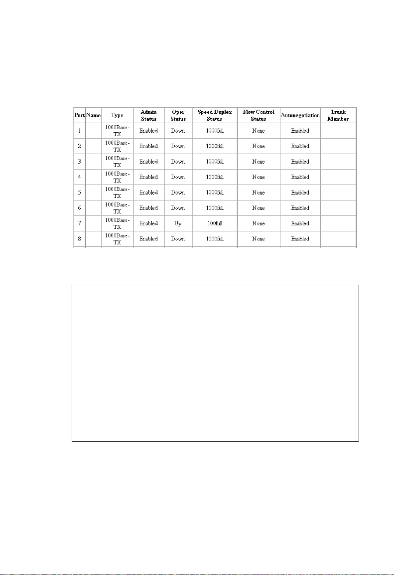
P
ORT CONFIGURATION
Web – Click Port/Port Information or Trunk Information. Modify the
required interface settings, and click “Apply.”
CLI – This example shows the connection status for Port 13.
Console#show interfaces status ethernet 1/13 3-76
Information of Eth 1/13
Basic information:
Port type: 1000t
Mac address: 00-00-11-11-22-2F
Configuration:
Name:
Port admin: Up
Speed-duplex: Auto
Capabilities: 10half, 10full, 100half, 100full, 1000full,
Broadcast storm: Enabled
Broadcast storm limit: 256 packets/second
Flow control: Disabled
Lacp: Disabled
Current status:
Link status: Down
Operation speed-duplex: 1000full
Flow control type: None
Console#
2-25
Page 56

C
ONFIGURING THE SWITCH
Configuring Interface Connections
You can use the Trunk Configuration or Port Configuration page to
enable/disable an interface, manually fix the speed and duplex mode, set
flow control, set auto-negotiation, and set the interface capabilities to
advertise.
Command Attributes
• Name – Allows you to label an interface. (Range: 1-64 characters)
• Admin – Allows you to manually disable an interface. You can disable
an interface due to abnormal behavior (e.g., excessive collisions), and
then reenable it after the problem has been resolved. You may also
disable an interface for security reasons.
• Speed/Duplex – Allows manual selection of port speed and duplex
mode (i.e., with auto-negotiation disabled).
• Flow Control – Allows automatic or manual selection of flow control.
- Flow control can eliminate frame loss by “blocking” traffic from end
stations or segments connected directly to the switch when its
buffers fill. When enabled, back pressure is used for half-duplex
operation and IEEE 802.3x for full-duplex operation.
- Flow control should not be used if a port is connected to a hub.
Otherwise flow control signals will be propagated throughout the
segment.
• Autonegotiation/Port Capabilities – Allows auto-negotiation to be
enabled/disabled. Specifies the capabilities to be advertised for a port
during auto-negotiation. The following capabilities are supported.
- 10half - Supports 10 Mbps half-duplex operation
- 10full - Supports 10 Mbps full-duplex operation
- 100half - Supports 100 Mbps half-duplex operation
- 100full - Supports 100 Mbps full-duplex operation
- 1000full - Supports 1000 Mbps full-duplex operation
- Sym - Transmits and receives pause frames for flow control
2-26
Page 57

P
ORT CONFIGURATION
- FC - Supports flow control
• Trunk – Indicates if a port is a member of a trunk. To create trunks
and select port members, see “Port Trunk Configuration” on page
2-64.
Note: Autonegotiation must be disabled before you can configure or
force the interface to use the Speed/Duplex Mode or Flow
Control options.
Web – Click Port/Port Configuration or Trunk Configuration. Modify the
required interface settings, and click “Apply.”
CLI – Select the interface, and then enter the required settings.
Console(config)#interface ethernet 1/13 3-69
Console(config-if)#description RD SW#13 3-69
Console(config-if)#shutdown 3-74
.
Console(config-if)#no shutdown
Console(config-if)#no negotiation 3-71
Console(config-if)#speed-duplex 100half 3-70
Console(config-if)#flowcontrol 3-73
.
Console(config-if)#negotiation
Console(config-if)#capabilities 100half 3-72
Console(config-if)#capabilities 100full
Console(config-if)#capabilities flowcontrol
2-27
Page 58

C
ONFIGURING THE SWITCH
Setting Broadcast Storm Thresholds
Broadcast storms may occur when a device on your network is
malfunctioning, or if application programs are not well designed or
properly configured. If there is too much broadcast traffic on your
network, performance can be severely degraded or everything can come to
complete halt.
You can protect your network from broadcast storms by setting a
threshold for broadcast traffic for each port. Any broadcast packets
exceeding the specified threshold will then be dropped.
Command Usage
• Default is enabled for all ports. Threshold: 256 packets per second
• Broadcast control does not effect IP multicast traffic.
Web – Click Port/Port Broadcast Control. Set the threshold for all ports
(16, 64, 128, or 256 pps), and then click “Apply.”
CLI – Specify the required interface, and then enter the threshold. The
following sets broadcast suppression at 128 packets per second on port 1.
Console(config)#interface ethernet 1/1 3-69
Console(config-if)#switchport broadcast packet-rate 128 3-75
Console(config-if)#
2-28
Page 59

P
ORT CONFIGURATION
Configuring Port Mirroring
You can mirror traffic from any source port to a target port for real-time
analysis. You can then attach a logic analyzer or RMON probe to the target
port and study the traffic crossing the source port in a completely
unobtrusive manner.
Command Usage
• The mirror port and monitor port speeds must match, otherwise traffic
may be dropped from the monitor port.
• The switch supports only one port mirror session.
• The source and target port have to be either both in the port group of
1 to 12 or both in the port group of 13 to 24.
Web – Click Port/Mirror. Specify the source port, the traffic type to be
mirrored, and the target port, then click “Add.”
CLI – Use the interface command to select the target port, then use the
port monitor command to specify the source port. Note that default
mirroring under the CLI is for both received and transmitted packets.
Console(config)#interface ethernet 1/10 3-69
Console(config-if)#port monitor ethernet 1/11 3-133
Console(config-if)#
2-29
Page 60
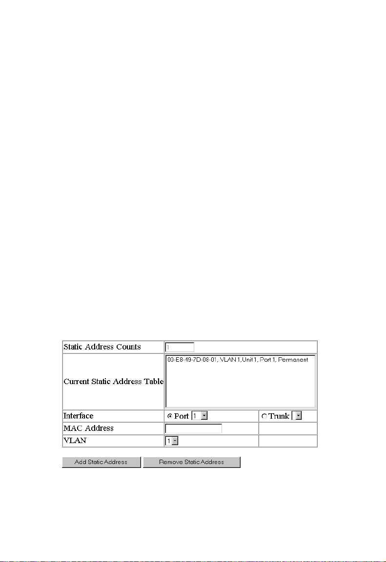
C
ONFIGURING THE SWITCH
Address Table Settings
Switches store the addresses for all known devices. This information is
used to route traffic directly between the inbound and outbound ports. All
the addresses learned by monitoring traffic are stored in the dynamic
address table. You can also manually configure static addresses that are
bound to a specific port.
Setting Static Addresses
A static address can be assigned to a specific interface on this switch. Static
addresses are bound to the assigned interface and will not be moved.
When a static address is seen on another interface, the address will be
ignored and will not be written to the address table.
Command Usage
Entries specified via the Web interface are permanent. Entries specified via
the CLI can be made permanent or can be set to be deleted on reset.
Web – Click Address Table/Static Addresses. Specify the interface, the
MAC address and VLAN, then click “Add Static Address.”
2-30
Page 61
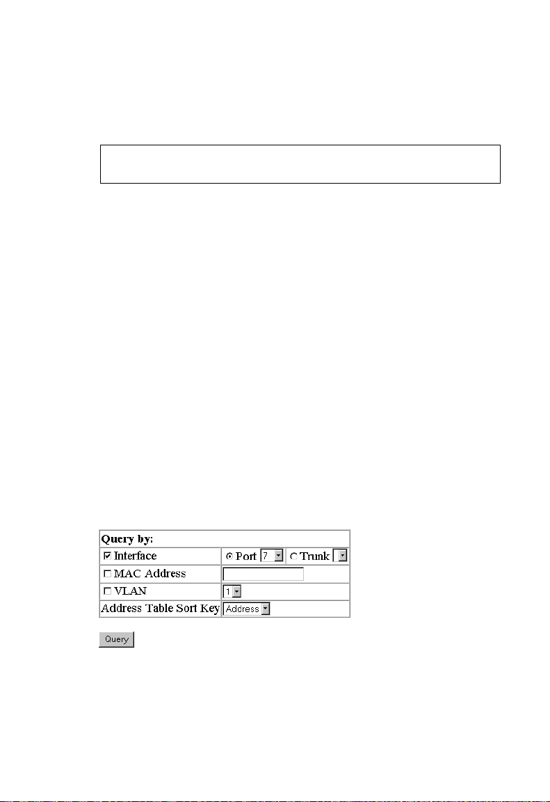
A
DDRESS TABLE SETTINGS
CLI – This example adds an address to the static address table, but sets it
to be deleted when the switch is reset.
Console(config)#bridge 1 address 00-e0-29-94-34-de vlan 1 forward
ethernet 1/1 delete-on-reset 3-80
Console(config)#
Displaying the Address Table
The Dynamic Address Table contains the MAC addresses learned by
monitoring the source address for traffic entering the switch. When the
destination address for inbound traffic is found in the database, the
packets intended for that address is forwarded directly to the associated
port. Otherwise, the traffic is broadcast to all ports.
Command Usage
• You can display entries in the dynamic address table by selecting an
interface (either port or trunk), MAC address, or VLAN.
• You can sort the information displayed based on interface (port or
trunk), MAC address, or VLAN.
Web – Click Address Table/Dynamic Addresses. Specify the search type
(i.e., Interface, MAC Address, or VLAN), the method of sorting the
displayed addresses, then click Query.
2-31
Page 62

C
ONFIGURING THE SWITCH
For example, the following screen shows the dynamic addresses for port 7.
CLI – This example also displays the address table entries for port 11.
Console#show bridge 1 ethernet 1/11 3-81
Interface Mac Address Vlan Type
--------- ----------------- ---- -----------------
Eth 1/11 00-10-b5-62-03-74 1 Learned
Console#
Changing the Aging Time
You can set the aging time for entries in the dynamic address table.
Command Usage
The range for the aging time is 17 - 2184 seconds. (The default is 300
seconds.)
Web – Click Address Table/Address Aging. Specify the new aging time,
then click “Apply.”
CLI – This example sets the aging time to 400 seconds.
Console(config)#bridge-group 1 aging-time 400 3-83
Console(config)#
2-32
Page 63

S
PANNING TREE PROTOCOL CONFIGURATION
Spanning Tree Protocol Configuration
The Spanning Tree Algorithm can be used to detect and disable network
loops, and to provide backup links between switches, bridges or routers.
This allows the switch to interact with other bridging devices (that is, an
STA-compliant switch, bridge or router) in your network to ensure that
only one route exists between any two stations on the network, and
provide backup links which automatically take over when a primary link
goes down.
Managing Global Settings
Global settings apply to the entire switch.
Command Attributes
The following global attributes are fixed and cannot be changed:
• Bridge ID – The priority and MAC address of this device.
• Designated Root – The priority and MAC address of the device in the
Spanning Tree that this switch has accepted as the root device.
• Root Port – The number of the port on this switch that is closest to
the root. This switch communicates with the root device through this
port. If there is no root port, then this switch has been accepted as the
root device of the Spanning Tree network.
• Root Path Cost – The path cost from the root port on this switch to
the root device.
• Configuration Changes – The number of times the Spanning Tree
has been reconfigured.
• Last Topology Change – The time since the Spanning Tree was last
reconfigured.
2-33
Page 64

C
ONFIGURING THE SWITCH
The following global attributes can be configured:
• Spanning Tree State – Enable/disabled this switch to participate in a
STA-compliant network.
• Priority – Bridge priority is used in selecting the root device, root port,
and designated port. The device with the highest priority becomes the
STA root device. However, if all devices have the same priority, the
device with the lowest MAC address will then become the root device.
(CLI only)
- Default: 32768
- Range: 0 - 65535
• Hello Time – Interval (in seconds) at which the root device transmits
a configuration message.
- Default: 2
- Minimum: 1
- Maximum: The lower of 10 or [(Max. Message Age / 2) -1]
• Maximum Age – The maximum time (in seconds) a device can wait
without receiving a configuration message before attempting to
reconfigure. All device ports (except for designated ports) should
receive configuration messages at regular intervals. Any port that ages
out STA information (provided in the last configuration message)
becomes the designated port for the attached LAN. If it is a root port,
a new root port is selected from among the device ports attached to the
network. (References to “ports” in this section means “interfaces,”
which includes both ports and trunks.)
- Default: 20
- Minimum: The higher of 6 or [2 x (Hello Time + 1)].
- Maximum: The lower of 40 or [2 x (Forward Delay - 1)]
2-34
Page 65

S
PANNING TREE PROTOCOL CONFIGURATION
• Forward Delay – The maximum time (in seconds) the root device will
wait before changing states (i.e., listening to learning to forwarding).
This delay is required because every device must receive information
about topology changes before it starts to forward frames. In addition,
each port needs time to listen for conflicting information that would
make it return to a blocking state; otherwise, temporary data loops
might result.
- Default: 15
- Minimum: The higher of 4 or [(Max. Message Age / 2) + 1]
- Maximum: 30
Displaying the current global settings for STA
Web – Click STA/STA Information.
2-35
Page 66

C
ONFIGURING THE SWITCH
CLI – This command displays global STA settings, followed by the
settings for each port.
Console#show bridge group 1 3-92
Bridge-group information
-------------------------------------------------------------Spanning tree protocol :ieee8021d
Spanning tree enable/disable :enable
Priority :32768
Hello Time (sec.) :2
Max Age (sec.) :20
Forward Delay (sec.) :15
Designated Root :32768.000011112222
Current root port :0
Current root cost :0
Number of topology changes :1
Last topology changes time (sec.):4576
Hold times (sec.) :1
---------------------------------------------------------------
Eth 1/ 1 information
-------------------------------------------------------------Admin status : enable
STA state : broken
Path cost : 4
Priority : 128
Designated cost : 0
Designated port : 128.1
Designated root : 32768.000011112222
Designated bridge : 32768.000011112222
Fast forwarding : disable
Forward transitions : 0
.
.
.
Note: The current root port and current root cost display as zero when
this device is not connected to the network.
2-36
Page 67

S
PANNING TREE PROTOCOL CONFIGURATION
Configuring the global settings for STA
Web – Click STA/STA Configuration. Modify the required attributes, click
“A p pl y. ”
CLI – This example enables Spanning Tree Protocol, and then sets the
indicated attributes.
Console(config)#bridge 1 spanning-tree 3-85
Console(config)#bridge 1 priority 40000 3-88
Console(config)#bridge 1 hello-time 5 3-87
Console(config)#bridge 1 max-age 40 3-87
Console(config)#bridge 1 forward-time 20 3-86
Managing STA Interface Settings
You can configure STA attributes for specific interfaces, including port
priority, path cost, and fast forwarding. You may use a different priority or
path cost for ports of same media type to indicate the preferred path.
Command Attributes
The following global attributes are read-only and cannot be changed:
• Port Status – Displays current state of this port within the Spanning
Tree:
2-37
Page 68

C
ONFIGURING THE SWITCH
• Disabled - The port has been disabled by the user or has failed
diagnostics.
• Blocking - Port receives STA configuration messages, but does
not forward packets.
• Listening - Port will leave blocking state due to a topology
change, start transmitting configuration messages, but does not
yet forward packets.
• Learning - Port has transmitted configuration messages for an
interval set by the Forward Delay parameter without receiving
contradictory information. Port address table is cleared, and the
port begins learning addresses.
• Forwarding - Port forwards packets, and continues learning
addresses.
• Broken - Port is malfunctioning or no link has been established.
• Forward Transitions – The number of times this port has
transitioned from the Learning state to the Forwarding state.
• Designated Cost – The cost for a packet to travel from this port to
the root in the current Spanning Tree configuration. The slower the
media, the higher the cost.
• Designated Bridge – The priority and MAC address of the device
through which this port must communicate to reach the root of the
Spanning Tree.
• Designated Port – The priority and number of the port on the
designated bridging device through which this switch must
communicate with the root of the Spanning Tree.
• Trunk Member – Indicates if a port is a member of a trunk.
2-38
Page 69

S
PANNING TREE PROTOCOL CONFIGURATION
The following interface attributes can be configured:
• Priority – Defines the priority used for this port in the Spanning Tree
Protocol. If the path cost for all ports on a switch are the same, the port
with the highest priority (i.e., lowest value) will be configured as an
active link in the Spanning Tree. This makes a port with higher priority
less likely to be blocked if the Spanning Tree Protocol is detecting
network loops. Where more than one port is assigned the highest
priority, the port with lowest numeric identifier will be enabled.
- Default: 128
- Range: 0 - 255
• Path Cost – This parameter is used by the STP to determine the best
path between devices. Therefore, lower values should be assigned to
ports attached to faster media, and higher values assigned to ports with
slower media. (Path cost takes precedence over port priority.)
• Full Range: 1-65535
• Recommended Range –
- Ethernet: 50-600
- Fast Ethernet: 10-60
- Gigabit Ethernet: 3-10
•Defaults –
- Ethernet – half duplex: 100; full duplex: 95; trunk: 90
- Fast Ethernet – half duplex: 19; full duplex: 18; trunk: 15
- Gigabit Ethernet – full duplex: 4; trunk: 3
• Fast Forwarding – Since end-nodes cannot cause forwarding loops,
they can be pass directly through to the forwarding state. Fast
Forwarding can achieve quicker convergence for end-node
workstations and servers, and also overcome other STA related
timeout problems. (Remember that Fast Forwarding should only be
enabled for ports connected to an end-node device.)
- Default is disabled
2-39
Page 70

C
ONFIGURING THE SWITCH
Web – Click STA/STA Port Information or STA Trunk Information.
CLI – This example shows the STA attributes for port 5.
Console#show bridge group 1 ethernet 1/5 3-92
Bridge-group information
-------------------------------------------------------------Spanning tree protocol :ieee8021d
Spanning tree enable/disable :enable
Priority :32768
Hello Time (sec.) :2
Max Age (sec.) :20
Forward Delay (sec.) :15
Designated Root :32768.0000e8000001
Current root port :13
Current root cost :4
Number of topology changes :325
Last topology changes time (sec.):18
Hold times (sec.) :1
---------------------------------------------------------------
Eth 1/ 5 information
-------------------------------------------------------------Admin status : enable
STA state : blocking
Path cost : 4
Priority : 128
Designated cost : 4
Designated port : 128.5
Designated root : 32768.0000e8000001
Designated bridge : 32768.222222222222
Fast forwarding : enable
Forward transitions : 18
Console#
2-40
Page 71

VLAN C
ONFIGURATION
Web – Click STA/STA Port Configuration or STA Trunk Configuration.
Modify the required attributes, then click “Apply.”
CLI – This example sets STA attributes for port 5.
Console(config)#interface ethernet 1/5 3-69
Console(config-if)#bridge-group 1 priority 0 3-90
Console(config-if)#bridge-group 1 path-cost 50 3-89
Console(config-if)#bridge-group 1 portfast 3-91
VLAN Configuration
In conventional networks with routers, broadcast traffic is split up into
separate domains. Switches do not inherently support broadcast domains.
This can lead to broadcast storms in large networks that handle traffic
such as IPX or NetBeui. By using IEEE 802.1Q-compliant VLANs, you
can organize any group of network nodes into separate broadcast domains,
thus confining broadcast traffic to the originating group. This also
provides a more secure and cleaner network environment.
An IEEE 802.1Q VLAN is a group of ports that can be located anywhere
in the network, but communicate as though they belong to the same
physical segment.
2-41
Page 72

C
ONFIGURING THE SWITCH
VLANs help to simplify network management by allowing you to move
devices to a new VLAN without having to change any physical
connections. VLANs can be easily organized to reflect departmental
groups (such as Marketing or R&D), usage groups (such as e-mail), or
multicast groups (used for multimedia applications such as
videoconferencing).
VLANs provide greater network efficiency by reducing broadcast traffic,
and allow you to make network changes without having to update IP
addresses or IP subnets. VLANs inherently provide a high level of network
security since traffic must pass through a configured Layer 3 link to reach a
different VLAN.
• Up to 255 VLANs based on the IEEE 802.1Q standard
• Distributed VLAN learning across multiple switches using explicit or
implicit tagging
• Port overlapping, allowing a port to participate in multiple VLANs
• End stations can belong to multiple VLANs
• Passing traffic between VLAN-aware and VLAN-unaware devices
• Priority tagging
Assigning Ports to VLANs
Before enabling VLANs for the switch, you must first assign each port to
the VLAN group(s) in which it will participate. By default all ports are
assigned to VLAN 1 as untagged ports. Add a port as a tagged port (that
is, a port attached to a VLAN-aware device) if you want it to carry traffic
for one or more VLANs and if the device at the other end of the link also
supports VLANs. Then assign the port at the other end of the link to the
same VLAN(s). However, if you want a port on this switch to participate
2-42
Page 73

VLAN C
in one or more VLANs, but the device at the other end of the link does
not support VLANs, then you must add this port as an untagged port (that
is, a port attached to a VLAN-unaware device).
VLAN Classification – When the switch receives a frame, it classifies the
frame in one of two ways. If the frame is untagged, the switch assigns the
frame to an associated VLAN (based on the PVID of the receiving port.
But if the frame is tagged, the switch uses the tagged VLAN ID to identify
the port broadcast domain of the frame.
Port Overlapping – Port overlapping can be used to allow access to
commonly shared network resources among different VLAN groups, such
as file servers or printers. Note that if you implement VLANs which do
not overlap, but still need to communicate, you can connect them by using
a Layer-3 router or switch.
Port-based VLANs – Port-based (or static) VLANs are manually tied to
specific ports. The switch’s forwarding decision is based on the destination
MAC address and its associated port. Therefore, to make valid forwarding
or flooding decisions, the switch must learn the relationship of the MAC
address to its related port—and thus to the VLAN—at run-time.
However, when GVRP is enabled, this process can be fully automatic.
ONFIGURATION
Automatic VLAN Registration – GVRP (GARP VLAN Registration
Protocol) defines a system whereby the switch can automatically learn the
VLANs to which each endstation should be assigned. If an endstation (or
its network adapter) supports the IEEE 802.1Q VLAN protocol, it can be
configured to broadcast a message to your network indicating the VLAN
groups it wants to join. When this switch receives these messages, it will
automatically place the receiving port in the specified VLANs, and then
forward the message to all other ports. When the message arrives at
another switch that supports GVRP, it will also place the receiving port in
the specified VLANs, and pass the message on to all other ports. VLAN
requirements are propagated in this way throughout the network. This
allows GVRP-compliant devices to be automatically configured for VLAN
groups based solely on endstation requests.
2-43
Page 74

C
ONFIGURING THE SWITCH
To implement GVRP in a network, you must first configure the static
VLANs required on switches that are connected to PCs, servers, and other
devices, so that these VLANs can be propagated across the network
(Web - VLAN / VLAN Membership). For other core switches in the
network, enable GVRP on the links between these devices
(Web - VLAN / Port Settings or Trunk Settings). You should also
determine security boundaries in the network and disable GVRP on ports
to prevent advertisements being propagated, or forbid ports from joining
restricted VLANs.
Forwarding Tagged/Untagged Frames
If you want to create a small port-based VLAN for devices attached
directly to a single switch, you can assign ports to the same untagged
VLAN. However, to participate in a VLAN group that crosses several
switches, you need to create a VLAN for that group and enable tagging on
all ports.
Ports can be assigned to multiple tagged or untagged VLANs. Each port
on the switch is therefore capable of passing tagged or untagged frames.
To forward a frame from a VLAN-aware device to a VLAN-unaware
device, the switch first decides where to forward the frame, and then strips
off the VLAN tag. However, to forward a frame from a VLAN-unaware
device to a VLAN-aware device, the switch first decides where to forward
the frame, and then inserts a VLAN tag reflecting this port’s default VID.
Displaying Basic VLAN Information
Command Attributes
• VLAN Version Number – The VLAN version used by this switch as
specified in the IEEE 802.1Q standard. (Web interface only.)
• Maximum VLAN ID – Maximum VLAN ID recognized by this
switch.
2-44
Page 75

VLAN C
ONFIGURATION
• Maximum Number of Supported VLANs – Maximum number of
VLANs that can be configured on this switch.
Web – Click VLAN/VLAN Basic Information.
CLI – Enter the following command.
Console#show bridge-ext 3-109
Max support vlan numbers: 255
Max support vlan ID: 4094
Extended multicast filtering services: No
Static entry individual port: Yes
VLAN learning: IVL
Configurable PVID tagging: Yes
Local VLAN capable: No
Traffic classes: Enabled
Global GVRP status: Enabled
GMRP: Disabled
Console#
Displaying Current VLANs
Command Attributes for Web Interface
• VLAN ID – ID of configured VLAN (1-4094, no leading zeroes).
• Up Time at Creation – Time this VLAN was created; i.e., System Up
Time.
• Status – Shows how this VLAN was added to the switch.
- Dynamic GVRP: Automatically learned via GVRP.
- Permanent: Added as a static entry.
• Tagged Ports – Shows the tagged VLAN port members.
• Untagged Ports – Shows the untagged VLAN port members
2-45
Page 76

C
ONFIGURING THE SWITCH
Web – Click VLAN/VLAN Current Table. Select any ID from the
scroll-down list.
Command Attributes for CLI Interface
• VLAN – ID of configured VLAN (1-4094, no leading zeroes).
• Type – Shows how this VLAN was added to the switch.
- Dynamic: Automatically learned via GVRP.
- Static: Added as a static entry.
• Name – Name of the VLAN (1 to 32 characters).
• Status – Shows if this VLAN is enabled or disabled.
- Active: VLAN is operational.
- Suspend: VLAN is suspended; i.e., does not pass packets.
• Ports / Channel groups – Shows the VLAN interface members.
2-46
Page 77

VLAN C
CLI – Current VLAN information can be displayed with the following
command.
Console#show vlan id 1 3-104
VLAN Type Name Status Ports/Channel groups
---- ------- ---------------- --------- --------------------------------------1 Static DefaultVlan Active Eth1/ 1 Eth1/ 2 Eth1/ 3 Eth1/ 4 Eth1/ 5
Console#
Eth1/ 6 Eth1/ 7 Eth1/ 8 Eth1/ 9 Eth1/10
Eth1/11 Eth1/12 Eth1/13 Eth1/14 Eth1/15
Eth1/16 Eth1/17 Eth1/18 Eth1/19 Eth1/20
Eth1/21 Eth1/22 Eth1/23 Eth1/24
Creating VLANs
Command Attributes
• VLAN ID – ID of configured VLAN (1-4094, no leading zeroes).
• Name – Name of the VLAN (1 to 32 characters).
• Status – Shows if this VLAN is enabled or disabled (Web).
- Enable: VLAN is operational.
- Disable: VLAN is suspended; i.e., does not pass packets.
• State – Shows if this VLAN is enabled or disabled (CLI).
- Active: VLAN is operational.
- Suspend: VLAN is suspended; i.e., does not pass packets.
ONFIGURATION
Web – Click VLAN/VLAN Static List. Enter the VLAN ID and VLAN
name, mark the Enable checkbox to activate the VLAN, and then click
Add.
2-47
Page 78

C
ONFIGURING THE SWITCH
CLI – This example creates a new VLAN.
Console(config)#vlan database 3-95
Console(config-vlan)#vlan 5 name R&D media ethernet state
active 3-96
Console(config-vlan)#
Adding Interfaces Based on Membership Type
Command Attributes
• Port – Port identifier.
• Trunk – Trunk identifier.
• VLAN – ID of configured VLAN (1-4094, no leading zeroes).
• Name – Name of the VLAN (1 to 32 characters).
• Status – Shows if this VLAN is enabled or disabled.
- Enable: VLAN is operational.
- Disable: VLAN is suspended; i.e., does not pass packets.
• Membership Type – Select VLAN membership for each interface by
marking the appropriate radio button for a port or trunk:
2-48
- Tagged: Interface is a member of the VLAN. All packets
transmitted by the port will be tagged, that is, carry a tag and
therefore carry VLAN or CoS information.
- Untagged: Interface is a member of the VLAN. All packets
transmitted by the port will be untagged, that is, not carry a tag and
therefore not carry VLAN or CoS information. Note that an
interface must be assigned to at least one group as an untagged port.
- Forbidden: Interface is forbidden from automatically joining the
VLAN via GVRP. For more information, see “GVRP” on page 81.
- None: Interface is not a member of the VLAN. Packets associated
with this VLAN will not be transmitted by the interface.
Page 79

VLAN C
ONFIGURATION
• Trunk Member – Indicates if a port is a member of a trunk. To add a
trunk to the selected VLAN, use the last table on the VLAN Static
Table page.
Web – Click VLAN/VLAN Static Table. Select a VLAN ID from the
scroll-down list. Modify the VLAN name and status if required. Select the
membership type by marking the appropriate radio button in the list of
ports or trunks. Click “Apply.”
CLI – The following example shows how to add tagged and untagged
ports to VLAN 2.
Console(config)#interface ethernet 1/1 3-69
Console(config-if)#switchport allowed vlan add 2 tagged 3-102
Console(config-if)#exit
Console(config)#interface ethernet 1/2
Console(config-if)#switchport allowed vlan add 2 untagged
Console(config-if)#exit
Console(config)#interface ethernet 1/13
Console(config-if)#switchport allowed vlan add 2 tagged
2-49
Page 80

C
ONFIGURING THE SWITCH
Adding Interfaces Based on Static Membership
Command Attributes
• Interface – Port or trunk identifier.
• Member – VLANs for which the selected interface is a tagged
member.
• Non-Member – VLANs for which the selected interface is not a
tagged member.
Web – Open VLAN/VLAN Static Membership. Select an interface from
the scroll-down box (Port or Trunk). Click “Query” to display VLAN
membership information for the interface. Select a VLAN ID, and then
click “Add” to add the interface as a tagged member, or click “Remove” to
remove the interface. After configuring VLAN membership for each
interface, click “Apply.”
CLI – This example adds Port 3 to VLAN 1 as a tagged port, and removes
Port 3 from VLAN 2.
Console(config)#interface ethernet 1/3 3-69
Console(config-if)#switchport allowed vlan add 1 tagged 3-102
Console(config-if)#switchport allowed vlan remove 2
2-50
Page 81

VLAN C
Configuring VLAN Behavior for Interfaces
You can configure VLAN behavior for specific interfaces, including the
default VLAN identifier (PVID), accepted frame types, ingress filtering,
GVRP status, and GARP timers.
Command Usage
• GVRP – GARP VLAN Registration Protocol defines a way for
switches to exchange VLAN information in order to automatically
register VLAN members on interfaces across the network.
• GARP – Group Address Registration Protocol is used by GVRP to
register or deregister client attributes for client services within a
bridged LAN. The default values for the GARP timers are
independent of the media access method or data rate. These values
should not be changed unless you are experiencing difficulties with
GVRP registration/deregistration.
Command Attributes
• PVID – The VLAN ID assigned to untagged frames received on the
interface. If the (CLI) switchport mode is set to trunk (see page 3-98),
the PVID will be inserted into all untagged frames sent from a tagged
port. (Default: 1)
ONFIGURATION
• Acceptable Frame Type – Sets the interface to accept all frame types,
including tagged or untagged frames, or only tagged frames. If only
tagged frames are accepted, the switch will only accept frames if the
frame tag matches a VLAN to which this interface has been assigned.
(Default: All)
• Ingress Filtering – If ingress filtering is enabled, incoming frames for
VLANs which do not include this ingress port in their member set will
be discarded at the ingress port. This will not affect VLAN
independent BPDU frames, such as GVRP or STP. (Default:
Disabled)
2-51
Page 82

C
ONFIGURING THE SWITCH
• GVRP Status – Enables/disables GVRP for the interface. GVRP
must be globally enabled for the switch before this setting can take
effect. (See “Displaying Bridge Extension Capabilities” on page 2-20.)
When disabled, any GVRP packets received on this port will be
discarded and no GVRP registrations will be propagated from other
ports. (Default: Enabled)
• GARP Join Timer – The interval between transmitting requests/
queries to participate in a VLAN group. (Default: 20 centiseconds)
• GARP Leave Timer – The interval a port waits before leaving a
VLAN group. This time should be set to more than twice the join time.
This ensures that after a Leave or LeaveAll message has been issued,
the applicants can rejoin before the port actually leaves the group.
(Default: 60 centiseconds)
• GARP LeaveAll Timer – The interval between sending out a
LeaveAll query message for VLAN group participants and the port
leaving the group. This interval should be considerably larger than the
Leave Time to minimize the amount of traffic generated by nodes
rejoining the group. (Default: 1000 centiseconds)
• Trunk Member – Indicates if a port is a member of a trunk. To add a
trunk to the selected VLAN, use the last table on the VLAN Static
Table page.
• Mode – Indicates VLAN membership mode for a port. (Configure via
CLI, see page 3-98.)
- 1Q Trunk – Specifies a port as an end-point for a VLAN trunk. A
trunk is a direct link between two switches, so the port transmits and
receives tagged frames that identify the source VLAN.
- Hybrid – Specifies a hybrid VLAN interface. The port may receive
or transmit tagged or untagged frames. Any frames that are not
tagged will be assigned to the default VLAN.
Note: Mode and the Acceptable Fame Type are comparable parameters.
2-52
Page 83

C
LASS OF SERVICE CONFIGURATION
Web – Click VLAN/VLAN Port Configuration or VLAN Trunk
Configuration. Fill in the required settings for each interface, click “Apply.”
CLI – This example sets port 1 to accept only tagged frames, assigns
PVID 3 as the native VLAN ID, enables GVRP, sets the GARP timers,
and then sets the switchport mode to hybrid.
Console(config)#interface ethernet 1/1 3-69
Console(config-if)#switchport acceptable-frame-types tagged 3-99
Console(config-if)#switchport ingress-filtering 3-100
Console(config-if)#switchport native vlan 3 3-101
Console(config-if)#switchport gvrp 3-105
Console(config-if)#garp timer join 10 3-107
Console(config-if)#garp timer leave 90 3-107
Console(config-if)#garp timer leaveall 2000 3-107
Console(config-if)#switchport mode hybrid 3-98
Console(config-if)#
Class of Service Configuration
Class of Service (CoS) allows you to specify which data packets have
greater precedence when traffic is buffered in the switch due to
congestion. This switch supports CoS with four priority queues for each
port. Data packets in a port’s high-priority queue will be transmitted before
those in the lower-priority queues. You can set the default priority for each
interface, and configure the mapping of frame priority tags to the switch’s
priority queues.
2-53
Page 84

C
ONFIGURING THE SWITCH
Setting the Default Priority for Interfaces
You can specify the default port priority for each interface on the switch.
All untagged packets entering the switch are tagged with the specified
default port priority, and then sorted into the appropriate priority queue at
the output port.
Command Usage
• This switch provides four priority queues for each port. It uses
Weighted Round Robin to prevent head-of-queue blockage.
• The default priority applies if the incoming frame is an untagged frame
received from a VLAN trunk or a static-access port. This priority does
not apply to IEEE 802.1Q VLAN tagged frames. If the incoming
frame is an IEEE 802.1Q VLAN tagged frame, the IEEE 802.1p User
Priority bits will be used.
• If the output port is an untagged member of the associated VLAN,
these frames are stripped of all VLAN tags prior to transmission.
Command Attributes
• Default Priority – The priority that is assigned to untagged frames
received on the specified port. (Range: 0 - 7, Default: 0)
• Number of Egress Traffic Classes – The number of queue buffers
provided for each port.
2-54
Page 85

C
LASS OF SERVICE CONFIGURATION
Web – Click Priority/Default Port Priority or Default Trunk Priority.
Modify the default priority for any interface, then click “Apply.”
CLI – This example assigns a default priority or 5 to port 3.
Console(config)#interface ethernet 1/3 3-69
Console(config-if)#switchport priority default 5 3-122
Mapping CoS Values to Egress Queues
This switch processes Class of Service (CoS) priority tagged traffic by
using four priority queues for each port, with service schedules based on
Weighted Round Robin (WRR). Up to eight separate traffic priorities are
defined in IEEE 802.1p. The default priority levels are assigned according
2-55
Page 86

C
ONFIGURING THE SWITCH
to recommendations in the IEEE 802.1p standard as shown in the
following table.
Queue
0123
0
1
2
3
Priority
4
5
6
7
The priority levels recommended in the IEEE 802.1p standard for various
network applications are shown in the following table. However, you can
map the priority levels to the switch’s output queues in any way that
benefits application traffic for your own network.
Priority Level Traffic Type
1Background
2(Spare)
0 (default) Best Effort
3 Excellent Effort
4 Controlled Load
5 Video, less than 100 milliseconds latency and jitter
6 Voice, less than 10 milliseconds latency and jitter
7 Network Control
• Priority – CoS value. (Range: 0 to 7, where 7 is the highest priority)
• Traffic Class – Output queue buffer. (Range: 0 - 3, where 3 is the
highest CoS priority queue)
2-56
Page 87

C
LASS OF SERVICE CONFIGURATION
Web – Click Priority/Traffic Classes. Assign priorities to the output
queues, then click “Apply.”
CLI – The following example shows how to map CoS values 0, 1 and 2 to
CoS priority queue 0, value 3 to CoS priority queue 1, values 4 and 5 to
CoS priority queue 2, and values 6 and 7 to CoS priority queue 3.
Console(config)#interface ethernet 1/1 3-69
Console(config)#queue cos-map0012 3-124
Console(config)#queue cos-map 1 3
Console(config)#queue cos-map245
Console(config)#queue cos-map367
Console(config)#exit
Console#show queue cos-map ethernet 1/1 3-126
Information of Eth 1/1
Queue ID Traffic class
-------- ------------0 012
13
245
367
Console#
2-57
Page 88

C
ONFIGURING THE SWITCH
Setting the Service Weight for Traffic Classes
This switch uses the Weighted Round Robin (WRR) algorithm to
determine the frequency at which it services each priority queue. As
described in “Mapping CoS Values to Egress Queues” on page 2-55, the
traffic classes are mapped to one of the four egress queues provided for
each port. You can assign a weight to each of these queues (and thereby to
the corresponding traffic priorities). This weight sets the frequency at
which each queue will be polled for service, and subsequently affects the
response time for software applications assigned a specific priority value.
Command Attributes
• WRR Setting Table – Displays a list of weights for each traffic class
(i.e., queue).
• Weight Value – Set a new weight for the selected traffic class.
Web – Open Priority/Queue Scheduling. Select a traffic class by clicking
on it with your cursor, enter a weight value, and then click “Apply.”
CLI – The following example shows how to assign WRR weights of 1, 4,
16 and 64 to the CoS priority queues 0, 1, 2 and 3.
Console(config)#queue bandwidth141664 3-123
Console(config)#exit
Console#show queue bandwidth 3-125
Queue ID Weight
-------- -----01
14
216
Console#
364
2-58
Page 89

C
LASS OF SERVICE CONFIGURATION
Mapping Layer 3/4 Priorities to CoS Values
This switch supports a common method of prioritizing layer 3/4 traffic to
meet application requirements. Traffic priorities can be specified in the IP
header of a frame, using the priority bits in the Type of Service (ToS) octet.
The ToS octet may contain three bits for IP Precedence or six bits for
Differentiated Services Code Point (DSCP) service. When these services
are enabled, the priorities are mapped to a Class of Service value by the
switch, and the traffic then sent to the corresponding output queue.
Because different priority information may be contained in the traffic, this
switch maps priority values to the output queues in the following manner:
• The precedence for priority mapping is IP Precedence or DSCP
Priority and then Default Port Priority.
• IP Precedence and DSCP Priority cannot both be enabled. Enabling
one of these priority types will automatically disable the other.
• IP Precedence and DSCP Priority settings are global and apply to all
ports on the switch.
Selecting IP Precedence/DSCP Priority
The switch allows you to choose between using IP Precedence or DSCP
priority. Select one of the methods or disable this feature.
Command Attributes
• IP Precedence/DSCP Priority Status – Selects IP Precedence,
DSCP, or disables both priority services.
Web – Click Priority/IP Precedence Priority. Select “IP Precedence” or
“IP DSCP” from the IP Precedence/DSCP Priority Status menu.
2-59
Page 90

C
ONFIGURING THE SWITCH
CLI – The following example globally enables IP Precedence service on
the switch.
Console(config)#map ip precedence 3-127
Console#
Mapping IP Precedence
The Type of Service (ToS) octet in the IPv4 header includes three
precedence bits defining eight different priority levels ranging from highest
priority for network control packets to lowest priority for routine traffic.
The default IP Precedence values are mapped one-to-one to Class of
Service values (i.e., Precedence value 0 maps to CoS value 0, and so forth).
Bits 6 and 7 are used for network control, and the other bits for various
application types. ToS bits are defined in the following table.
Priority Level Traffic Type
7 Network Control
6 Internetwork Control
5Critical
4Flash Override
3Flash
2 Immediate
1Priority
0Routine
Command Attributes
• IP Precedence Priority Table – Shows the IP Precedence to CoS
map.
• Class of Service Value – Maps a CoS value to the selected IP
Precendence value. Note that “0” represents low priority and “7”
represent high priority.
2-60
Page 91
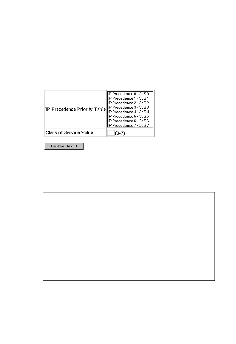
C
LASS OF SERVICE CONFIGURATION
Web – Click Priority/IP Precedence Priority. Select an IP Precedence value
from the IP Precedence Priority Table by clicking on it with your cursor,
enter a value in the Class of Service Value field, and then click “Apply.” Be
sure to also select “IP Precedence” from the IP Precedence/DSCP
Priority Status menu.
CLI – The following example globally enables IP Precedence service on
the switch, maps IP Precedence value 1 to CoS value 0 on port 5, and then
displays all the IP Precedence settings for that port. (Note that the setting
is global and applies to all ports on the switch.)
Console(config)#map ip precedence 3-127
Console(config)#interface ethernet 1/5 3-69
Console(config-if)#map ip precedence 1 cos 0 3-127
Console(config-if)#end
Console#show map ip precedence ethernet 1/5 3-131
Precedence mapping status: disabled
Port Precedence COS
--------- ---------- --Eth 1/ 5 0 0
Eth 1/ 5 1 0
Eth 1/ 5 2 2
Eth 1/ 5 3 3
Eth 1/ 5 4 4
Eth 1/ 5 5 5
Eth 1/ 5 6 6
Eth 1/ 5 7 7
Console#
2-61
Page 92

C
ONFIGURING THE SWITCH
Mapping DSCP Priority
The DSCP is six bits wide, allowing coding for up to 64 different
forwarding behaviors. The DSCP replaces the ToS bits, and it retains
backward compatibility with the three precedence bits so that non-DSCP
compliant, ToS-enabled devices, will not conflict with the DSCP mapping.
Based on network policies, different kinds of traffic can be marked for
different kinds of forwarding. The DSCP default values are defined in the
following table. Note that all the DSCP values that are not specified are
mapped to CoS value 0.
IP DSCP Value CoS Value
00
81
10, 12, 14, 16 2
18, 20, 22, 24 3
26, 28, 30, 32, 34, 36 4
38, 40, 42 5
48 6
46, 56 7
Command Attributes
• DSCP Priority Table – Shows the DSCP Priority to CoS map.
• Class of Service Value – Maps a CoS value to the selected DSCP
Priority value. Note that “0” represents low priority and “7” represent
high priority.
Web – Click Priority/IP DSCP Priority. Select a DSCP priority value from
the DSCP Priority Table by clicking on it with your cursor, enter a value in
the Class of Service Value field, and then click “Apply.” Be sure to also
select “IP DSCP” from the IP Precedence/DSCP Priority Status menu.
2-62
Page 93

C
LASS OF SERVICE CONFIGURATION
CLI – The following example globally enables DSCP Priority service on
the switch, maps DSCP value 1 to CoS value 0 on port 5, and then displays
all the DSCP Priority settings for that port. (Note that the setting is global
and applies to all ports on the switch.)
Console(config)#map ip dscp 3-129
Console(config)#interface ethernet 1/5 3-69
Console(config-if)#map ip dscp 1 cos 0 3-129
Console(config-if)#end
Console#show map ip dscp ethernet 1/5 3-132
DSCP mapping status: disabled
Port DSCP COS
--------- ---- --Eth 1/ 5 0 0
Eth 1/ 5 1 0
Eth 1/ 5 2 0
Eth 1/ 5 3 0
.
.
.
Eth 1/ 5 61 0
Eth 1/ 5 62 0
Eth 1/ 5 63 0
Console#
2-63
Page 94

C
ONFIGURING THE SWITCH
Port Trunk Configuration
Ports can be combined into an aggregate link to increase the bandwidth of
a network connection where bottlenecks exist or to ensure fault recovery.
You can create up to six trunks at a time, with any single trunk containing
up to four ports.
The switch supports both static trunking and dynamic LACP (Link
Aggregation Control Protocol). LACP configured ports can automatically
negotiate a trunked link with LACP-configured ports on another device.
You can enable LACP on any port that is not already a member of a static
trunk. If LACP is also enabled for the connected ports on another device,
the switch and the other device will automatically create a trunked link.
Besides balancing the load across each port in the trunk, the other ports
provide redundancy by taking over the load if a port in the trunk fails.
However, before making any physical connections between devices, use
the Web interface or CLI to specify the trunk on the devices at both ends.
When using a port trunk, take note of the following points:
• Finish configuring port trunks before you connect the corresponding
network cables between switches to avoid creating a loop.
• The ports at both ends of a connection must be configured as trunk
ports.
• The ports at both ends of a trunk must be configured in an identical
manner, including communication mode (i.e., speed, duplex mode and
flow control), VLAN assignments, and CoS settings.
• All ports on both ends of an LACP trunk must be configured for full
duplex, either by forced mode or auto-negotiation.
• All the ports in a trunk have to be treated as a whole when moved
from/to, added or deleted from a VLAN.
• STP, VLAN, and IGMP settings can only be made for the entire trunk.
2-64
Page 95

P
ORT TRUNK CONFIGURATION
Dynamically Configuring a Trunk with LACP
Web – Click Trunk/LACP Configuration. Select any of the switch ports
from the scroll-down port list and click “Add.” After you have completed
adding ports to the member list, click “Apply.”
CLI – The following example enables LACP for ports 17 and 18. Just
connect these ports to two LACP-enabled trunk ports on another switch
to form a trunk.
Console(config)#interface ethernet 1/17 3-69
Console(config-if)#lacp 3-137
Console(config-if)#exit
Console(config)#interface ethernet 1/18
Console(config-if)#lacp
Console(config-if)#end
Console#show interfaces status port-channel 1 3-76
Information of Trunk 1
Basic information:
Port type: 1000t
Mac address: 22-22-22-22-22-2d
Configuration:
Name:
Port admin status: Up
Speed-duplex: Auto
Capabilities: 10half, 10full, 100half, 100full, 1000full,
Flow control status: Disabled
Current status:
Created by: Lacp
Link status: Up
Port operation status: Up
Operation speed-duplex: 1000full
Flow control type: None
Member Ports: Eth1/17, Eth1/18,
Console#
2-65
Page 96

C
ONFIGURING THE SWITCH
Statically Configuring a Trunk
Web – Click Trunk/Trunk Configuration. Enter a trunk ID of 1-6 in the
Trunk field, select any of the switch ports from the scroll-down port list,
and click “Add.” After you have completed adding ports to the member
list, click “Apply.”
CLI – This example creates trunk 1 with ports 11 and 12. Just connect
these ports to two static trunk ports on another switch to form a trunk.
Console(config)#interface port-channel 1 3-69
Console(config-if)#exit
Console(config)#interface ethernet 1/11 3-69
Console(config-if)#channel-group 1 3-136
Console(config-if)#exit
Console(config)#interface ethernet 1/12
Console(config-if)#channel-group 1
Console(config-if)#end
Console#show interfaces status port-channel 1 3-76
Information of Trunk 1
Basic information:
Port type: 1000t
Mac address: 22-22-22-22-22-2c
Configuration:
Name:
Port admin status: Up
Speed-duplex: Auto
Capabilities: 10half, 10full, 100half, 100full, 1000full,
Flow control status: Disabled
Current status:
Created by: User
Link status: Up
Port operation status: Up
Operation speed-duplex: 1000full
Flow control type: None
Member Ports: Eth1/11, Eth1/12,
Console#
2-66
Page 97

C
ONFIGURING
Configuring SNMP
The switch includes an onboard agent that continuously monitors the
status of its hardware, as well as the traffic passing through its ports, based
on the Simple Network Management Protocol (SNMP). A network
management station can access this information using software such as
EliteView. Access rights to the onboard agent are controlled by community
strings. To communicate with the switch, the management station must
first submit a valid community string for authentication. The options for
configuring community strings and related trap functions are described in
the following sections.
Setting Community Access Strings
You may configure up to five community strings authorized for
management access. For security reasons, you should consider removing
the default strings.
Command Attributes
Community String – A community string that acts like a password and
permits access to the SNMP protocol.
SNMP
Access Mode
• Read-Only – Specifies read-only access. Authorized management
stations are only able to retrieve MIB objects.
• Read/Write – Specifies read-write access. Authorized management
stations are able to both retrieve and modify MIB objects.
Web – Click SNMP/SNMP Configuration. Enter a new string in the
Community String box and select the access rights from the Access Mode
drop-down list, then click “Add.”
2-67
Page 98

C
ONFIGURING THE SWITCH
CLI – The following example adds the string “spiderman” with read/write
access.
Console(config)#snmp-server community spiderman rw 3-4 4
Console(config)#
Specifying Trap Managers
You can specify up to five management stations that will receive
authentication failure messages and other trap messages from the switch.
Command Usage
• You can enable or disable authentication messages via the Web
interface.
• You can enable or disable authentication messages, link-up-down
messages, or all notification types via the CLI.
Web – Click SNMP/SNMP Configuration. Fill in the Trap Manager IP
Address box and the Trap Manager Community String box, mark Enable
Authentication Traps if required, and then click “Add.”
2-68
Page 99

M
ULTICAST CONFIGURATION
CLI – This example adds a trap manager and enables authentication traps.
Console(config)#snmp-server host 10.1.19.23 batman 3-4 6
Console(config)#snmp-server enable traps authentication 3-48
Multicast Configuration
Multicasting is used to support real-time applications such as video
conferencing or streaming audio. A multicast server does not have to
establish a separate connection with each client. It merely broadcasts its
service to the network, and any hosts that want to receive the multicast
register with their local multicast switch/router. Although this approach
reduces the network overhead required by a multicast server, the broadcast
traffic must be carefully pruned at every multicast switch/router it passes
through to ensure that traffic is only passed on the hosts which subscribed
to this service.
This switch uses IGMP (Internet Group Management Protocol) to query
for any attached hosts that want to receive a specific multicast service. It
identifies the ports containing hosts requesting to join the service and
sends data out to those ports only. It then propagates the service request
up to any neighboring multicast switch/router to ensure that it will
continue to receive the multicast service. This procedure is called multicast
filtering.
2-69
Page 100

C
ONFIGURING THE SWITCH
The purpose of IP multicast filtering is to optimize a switched network’s
performance, so multicast packets will only be forwarded to those ports
containing multicast group hosts or multicast routers/switches, instead of
flooding traffic to all ports in the subnet (VLAN).
Configuring IGMP Parameters
You can configure the switch to forward multicast traffic intelligently.
Based on the IGMP query and report messages, the switch forwards traffic
only to the ports that request multicast traffic. This prevents the switch
from broadcasting the traffic to all ports and possibly disrupting network
performance.
Command Usage
• IGMP Snooping – This switch can passively snoop on IGMP Query
and Report packets transferred between IP multicast routers/switches
and IP multicast host groups to identify the IP multicast group
members. It simply monitors the IGMP packets passing through it,
picks out the group registration information, and configures multicast
filters accordingly.
• IGMP Query – A router, or multicast-enabled switch, can periodically
ask their hosts if they want to receive multicast traffic. If there is more
than one router/switch on the LAN performing IP multicasting, one
of these devices is elected “querier” and assumes the role of querying
the LAN for group members. It then propagates the service requests
on to any adjacent multicast switch/router to ensure that it will
continue to receive the multicast service.
Note: Multicast routers use this information, along with a multicast
routing protocol such as DVMRP, to support IP multicasting
across the Internet.
2-70
 Loading...