

Page 1

Page 2

Page 3

54 Mbps Wireless Router
with built-in ADSL Modem
From SMC’s line of award-winning connectivity solutions
38 Tesla
Irvine, CA 92618
Phone: (949) 679-8000
May 2006
R.01 f/w 0.07b
Page 4

Information furnished is believed to be accurate and reliable. However, no responsibility is assumed by our
company for its use, nor for any infringements of patents or other rights of third parties which may result
from its use. No license is granted by implication or otherwise under any patent or patent rights of our
company. We reserve the right to change specifications at any time without notice.
Copyright © 2006 by
SMC Networks, Inc.
38 Tesla
Irvine, CA 92618
All rights reserved.
Trademarks:
SMC is a registered trademark; and Barricade is a trademark of SMC Networks, Inc. Other product and
company names are trademarks or registered trademarks of their respective holders.
Page 5

L
IMITED
Limited Warranty Statement: SMC Networks, Inc. (“SMC”) warrants its products to be
free from defects in workmanship and materials, under normal use and service, for the
applicable warranty term. All SMC products carry a standard 90-day limited warranty from
the date of purchase from SMC or its Authorized Reseller. SMC may, at its own discretion,
repair or replace any product not operating as warranted with a similar or functionally
equivalent product, during the applicable warranty term. SMC will endeavor to repair or
replace any product returned under warranty within 30 days of receipt of the product.
The standard limited warranty can be upgraded to a Limited Lifetime* warranty by registering
new products within 30 days of purchase from SMC or its Authorized Reseller. Registration
can be accomplished via the enclosed product registration card or online via the SMC web
site. Failure to register will not affect the standard limited warranty. The Limited Lifetime
warranty covers a product during the Life of that Product, which is defined as the period of
time during which the product is an “Active” SMC product. A product is considered to be
“Active” while it is listed on the current SMC price list. As new technologies emerge, older
technologies become obsolete and SMC will, at its discretion, replace an older product in its
product line with one that incorporates these newer technologies. At that point, the obsolete
product is discontinued and is no longer an “Active” SMC product. A list of discontinued
products with their respective dates of discontinuance can be found at:
http://www.smc.com/index.cfm?action=customer_service_warranty.
All products that are replaced become the property of SMC. Replacement products may be
either new or reconditioned. Any replaced or repaired product carries either a 30-day limited
warranty or the remainder of the initial warranty, whichever is longer. SMC is not responsible
for any custom software or firmware, configuration information, or memory data of
Customer contained in, stored on, or integrated with any products returned to SMC pursuant
to any warranty. Products returned to SMC should have any customer-installed accessory or
add-on components, such as expansion modules, removed prior to returning the product for
replacement. SMC is not responsible for these items if they are returned with the product.
Customers must contact SMC for a Return Material Authorization number prior to returning
any product to SMC. Proof of purchase may be required. Any product returned to SMC
without a valid Return Material Authorization (RMA) number clearly marked on the outside
of the package will be returned to customer at customer’s expense. For warranty claims within
North America, please call our toll-free customer support number at (800) 762-4968.
Customers are responsible for all shipping charges from their facility to SMC. SMC is
responsible for return shipping charges from SMC to customer.
W
ARRANTY
v
Page 6

L
IMITED WARRANTY
WARRANTIES EXCLUSIVE: IF AN SMC PRODUCT DOES NOT OPERATE AS
WARRANTED ABOVE, CUSTOMER’S SOLE REMEDY SHALL BE REPAIR OR
REPLACEMENT OF THE PRODUCT IN QUESTION, AT SMC’S OPTION. THE
FOREGOING WARRANTIES AND REMEDIES ARE EXCLUSIVE AND ARE IN
LIEU OF ALL OTHER WARRANTIES OR CONDITIONS, EXPRESS OR IMPLIED,
EITHER IN FACT OR BY OPERATION OF LAW, STATUTORY OR OTHERWISE,
INCLUDING WARRANTIES OR CONDITIONS OF MERCHANTABILITY AND
FITNESS FOR A PARTICULAR PURPOSE. SMC NEITHER ASSUMES NOR
AUTHORIZES ANY OTHER PERSON TO ASSUME FOR IT ANY OTHER
LIABILITY IN CONNECTION WITH THE SALE, INSTALLATION,
MAINTENANCE OR USE OF ITS PRODUCTS. SMC SHALL NOT BE LIABLE
UNDER THIS WARRANTY IF ITS TESTING AND EXAMINATION DISCLOSE THE
ALLEGED DEFECT IN THE PRODUCT DOES NOT EXIST OR WAS CAUSED BY
CUSTOMER’S OR ANY THIRD PERSON’S MISUSE, NEGLECT, IMPROPER
INSTALLATION OR TESTING, UNAUTHORIZED ATTEMPTS TO REPAIR, OR
ANY OTHER CAUSE BEYOND THE RANGE OF THE INTENDED USE, OR BY
ACCIDENT, FIRE, LIGHTNING, OR OTHER HAZARD.
LIMITATION OF LIABILITY: IN NO EVENT, WHETHER BASED IN CONTRACT
OR TORT (INCLUDING NEGLIGENCE), SHALL SMC BE LIABLE FOR
INCIDENTAL, CONSEQUENTIAL, INDIRECT, SPECIAL, OR PUNITIVE
DAMAGES OF ANY KIND, OR FOR LOSS OF REVENUE, LOSS OF BUSINESS, OR
OTHER FINANCIAL LOSS ARISING OUT OF OR IN CONNECTION WITH THE
SALE, INSTALLATION, MAINTENANCE, USE, PERFORMANCE, FAILURE, OR
INTERRUPTION OF ITS PRODUCTS, EVEN IF SMC OR ITS AUTHORIZED
RESELLER HAS BEEN ADVISED OF THE POSSIBILITY OF SUCH DAMAGES.
SOME STATES DO NOT ALLOW THE EXCLUSION OF IMPLIED WARRANTIES
OR THE LIMITATION OF INCIDENTAL OR CONSEQUENTIAL DAMAGES FOR
CONSUMER PRODUCTS, SO THE ABOVE LIMITATIONS AND EXCLUSIONS
MAY NOT APPLY TO YOU. THIS WARRANTY GIVES YOU SPECIFIC LEGAL
RIGHTS, WHICH MAY VARY FROM STATE TO STATE. NOTHING IN THIS
WARRANTY SHALL BE TAKEN TO AFFECT YOUR STATUTORY RIGHTS.
* SMC will provide warranty service for one year following discontinuance from the active
SMC price list. Under the limited lifetime warranty, internal and external power supplies, fans,
and cables are covered by a standard one-year warranty from date of purchase.
vi
SMC Networks, Inc.
38 Tesla
Irvine, CA 92618
Page 7

C
OMPLIANCES
EC Conformance Declaration
SMC contact for these products in Europe is:
SMC Networks Europe,
Edificio Conata II,
Calle Fructuós Gelabert 6-8, 2o, 4a,
08970 - Sant Joan Despí,
Barcelona, Spain.
Marking by the above symbol indicates compliance with the Essential Requirements of the
R&TTE Directive of the European Union (1999/5/EC). This equipment meets the
following conformance standards:
EN 300 328 V1.6.1 (11-2004)
EN 301 489-1 V1.5.1 (11-2004)
EN 301 489-17 V1.2.1 (08-2002)
EN 60950-1 : 2001
CSA Statement
This unit is to be used with an external power adaptor of a Class 2 or level 3 type and
Approved type suitable for use in the North America of equipment installation, having an
output voltage rating of 12 V dc, and output current rating of 1.0A or equivalent. The
external AC adapter must be complied with the requirements of LPS (Limited Power
Sources).
vii
Page 8

C
OMPLIANCES
Federal Communication Commission Interference Statement
This equipment has been tested and found to comply with the limits for a Class B digital
device, pursuant to Part 15 of the FCC Rules. These limits are designed to provide
reasonable protection against harmful interference in a residential installation. This
equipment generates, uses and can radiate radio frequency energy and, if not installed and
used in accordance with the instructions, may cause harmful interference to radio
communications. However, there is no guarantee that interference will not occur in a
particular installation. If this equipment does cause harmful interference to radio or
television reception, which can be determined by turning the equipment off and on, the user
is encouraged to try to correct the interference by one of the following measures:
• Reorient or relocate the receiving antenna.
• Increase the separation between the equipment and receiver.
• Connect the equipment into an outlet on a circuit different from that to which the receiver
is connected.
• Consult the dealer or an experienced radio/TV technician for help.
This device complies with Part 15 of the FCC Rules. Operation is subject to the following
two conditions: (1) This device may not cause harmful interference, and (2) this device must
accept any interference received, including interference that may cause undesired operation.
FCC Caution: Any changes or modifications not expressly approved by the party
responsible for compliance could void the user's authority to operate this equipment.
IMPORTANT NOTE:
FCC Radiation Exposure Statement:
This equipment complies with FCC radiation exposure limits set forth for an uncontrolled
environment. This equipment should be installed and operated with minimum distance 20cm
between the radiator and your body.
This transmitter must not be co-located or operating in conjunction with any other antenna
or transmitter.
IEEE 802.11b or 802.11g operation of this product in the U.S.A. is firmware-limited to
channels 1 through 11.
viii
Page 9

C
OMPLIANCES
Safety Compliance
Wichtige Sicherheitshinweise (Germany)
1. Bitte lesen Sie diese Hinweise sorgfältig durch.
2. Heben Sie diese Anleitung für den späteren Gebrauch auf.
3. Vor jedem Reinigen ist das Gerät vom Stromnetz zu trennen. Verwenden Sie keine
Flüssigoder Aerosolreiniger. Am besten eignet sich ein angefeuchtetes Tuch zur
Reinigung.
4. Die Netzanschlu ßsteckdose soll nahe dem Gerät angebracht und leicht zugänglich sein.
5. Das Gerät ist vor Feuchtigkeit zu schützen.
6. Bei der Aufstellung des Gerätes ist auf sicheren Stand zu achten. Ein Kippen oder Fallen
könnte Beschädigungen hervorrufen.
7. Die Belüftungsöffnungen dienen der Luftzirkulation, die das Gerät vor Überhitzung
schützt. Sorgen Sie dafür, daß diese Öffnungen nicht abgedeckt werden.
8. Beachten Sie beim Anschluß an das Stromnetz die Anschlußwerte.
9. Verlegen Sie die Netzanschlußleitung so, daß niemand darüber fallen kann. Es sollte auch
nichts auf der Leitung abgestellt werden.
10. Alle Hinweise und Warnungen, die sich am Gerät befinden, sind zu beachten.
11. Wird das Gerät über einen längeren Zeitraum nicht benutzt, sollten Sie es vom Stromnetz
trennen. Somit wird im Falle einer Überspannung eine Beschädigung vermieden.
12. Durch die Lüftungsöffnungen dürfen niemals Gegenstände oder Flüssigkeiten in das
Gerät gelangen. Dies könnte einen Brand bzw. elektrischen Schlag auslösen.
13. Öffnen sie niemals das Gerät. Das Gerät darf aus Gründen der elektrischen Sicherheit
nur von authorisiertem Servicepersonal geöffnet werden.
14. Wenn folgende Situationen auftreten ist das Gerät vom Stromnetz zu trennen und von
einer qualifizierten Servicestelle zu überprüfen:
a. Netzkabel oder Netzstecker sind beschädigt.
b. Flüssigkeit ist in das Gerät eingedrungen.
c. Das Gerät war Feuchtigkeit ausgesetzt.
d. Wenn das Gerät nicht der Bedienungsanleitung entsprechend funktioniert oder Sie mit
Hilfe dieser Anleitung keine Verbesserung erzielen.
e. Das Gerät ist gefallen und/oder das Gehäuse ist beschädigt.
f. Wenn das Gerät deutliche Anzeichen eines Defektes aufweist.
15. Zum Netzanschluß dieses Gerätes ist eine geprüfte Leitung zu verwenden. Für einen
Nennstrom bis 6 A und einem Gerätegewicht größer 3 kg ist eine Leitung nicht leichter
als H05VV-F, 3G, 0.75 mm
Der arbeitsplatzbezogene Schalldruckpegel nach DIN 45 635 Teil 1000 beträgt 70 dB(A) oder
weniger.
2
einzusetzen.
ix
Page 10

C
OMPLIANCES
x
Page 11

T
ABLE OF
C
ONTENTS
Introduction . . . . . . . . . . . . . . . . . . . . . . . . . . . . . . . . . 1-1
About the Barricade . . . . . . . . . . . . . . . . . . . . . . . . . . . . . . . . . . . . . . . . . 1-1
Features and Benefits . . . . . . . . . . . . . . . . . . . . . . . . . . . . . . . . . . . . . . . . 1-1
Applications . . . . . . . . . . . . . . . . . . . . . . . . . . . . . . . . . . . . . . . . . . . . . . . 1-2
Installation . . . . . . . . . . . . . . . . . . . . . . . . . . . . . . . . . . 2-1
Package Contents . . . . . . . . . . . . . . . . . . . . . . . . . . . . . . . . . . . . . . . . . . . 2-1
System Requirements . . . . . . . . . . . . . . . . . . . . . . . . . . . . . . . . . . . . . . . . 2-2
Hardware Description . . . . . . . . . . . . . . . . . . . . . . . . . . . . . . . . . . . . . . . 2-2
LED Indicators . . . . . . . . . . . . . . . . . . . . . . . . . . . . . . . . . . . . . . . 2-4
ISP Settings . . . . . . . . . . . . . . . . . . . . . . . . . . . . . . . . . . . . . . . . . . . . . . . . 2-5
Connect the System . . . . . . . . . . . . . . . . . . . . . . . . . . . . . . . . . . . . . . . . . 2-5
Connecting the ADSL Line . . . . . . . . . . . . . . . . . . . . . . . . . . . . . 2-5
Connecting the network . . . . . . . . . . . . . . . . . . . . . . . . . . . . . . . . 2-6
Connecting the Power Adapter . . . . . . . . . . . . . . . . . . . . . . . . . . 2-7
Wall Mounting . . . . . . . . . . . . . . . . . . . . . . . . . . . . . . . . . . . . . . . 2-7
Configuring Client PC . . . . . . . . . . . . . . . . . . . . . . . . . 3-1
TCP/IP Configuration . . . . . . . . . . . . . . . . . . . . . . . . . . . . . . . . . . . . . . . 3-2
Windows 98/Me . . . . . . . . . . . . . . . . . . . . . . . . . . . . . . . . . . . . . . . . . . . . 3-2
Disable HTTP Proxy . . . . . . . . . . . . . . . . . . . . . . . . . . . . . . . . . . 3-4
Obtain IP Settings from Your ADSL Router . . . . . . . . . . . . . . . 3-6
Windows NT 4.0 . . . . . . . . . . . . . . . . . . . . . . . . . . . . . . . . . . . . . . . . . . . 3-7
Disable HTTP Proxy . . . . . . . . . . . . . . . . . . . . . . . . . . . . . . . . . . 3-9
Obtain IP Settings from Your Barricade . . . . . . . . . . . . . . . . . . . 3-9
Windows 2000 . . . . . . . . . . . . . . . . . . . . . . . . . . . . . . . . . . . . . . . . . . . . 3-11
Disable HTTP Proxy . . . . . . . . . . . . . . . . . . . . . . . . . . . . . . . . . 3-12
Obtain IP Settings from Your Barricade . . . . . . . . . . . . . . . . . . 3-12
Windows XP . . . . . . . . . . . . . . . . . . . . . . . . . . . . . . . . . . . . . . . . . . . . . . 3-14
Disable HTTP Proxy . . . . . . . . . . . . . . . . . . . . . . . . . . . . . . . . . 3-14
Obtain IP Settings from Your Barricade . . . . . . . . . . . . . . . . . . 3-14
Configuring Your Macintosh Computer . . . . . . . . . . . . . . . . . . . . . . . . 3-16
Disable HTTP Proxy . . . . . . . . . . . . . . . . . . . . . . . . . . . . . . . . . 3-17
xi
Page 12

T
ABLE OF CONTENTS
Configuring the ADSL Router . . . . . . . . . . . . . . . . . . . 4-1
Navigating the Management Interface . . . . . . . . . . . . . . . . . . . . . . . . . . 4-2
Making Configuration Changes . . . . . . . . . . . . . . . . . . . . . . . . . . 4-3
Setup Wizard . . . . . . . . . . . . . . . . . . . . . . . . . . . . . . . . . . . . . . . . . . . . . . 4-4
Time Zone . . . . . . . . . . . . . . . . . . . . . . . . . . . . . . . . . . . . . . . . . . 4-4
Wireless Settings . . . . . . . . . . . . . . . . . . . . . . . . . . . . . . . . . . . . . . 4-5
ADSL Settings . . . . . . . . . . . . . . . . . . . . . . . . . . . . . . . . . . . . . . . 4-6
Summary . . . . . . . . . . . . . . . . . . . . . . . . . . . . . . . . . . . . . . . . . . . . 4-7
ADSL Settings - Country or ISP Not Listed . . . . . . . . . . . . . . . . 4-9
Configuration Parameters . . . . . . . . . . . . . . . . . . . . . . . . . . . . . . . . . . . 4-17
System . . . . . . . . . . . . . . . . . . . . . . . . . . . . . . . . . . . . . . . . . . . . . 4-19
WAN . . . . . . . . . . . . . . . . . . . . . . . . . . . . . . . . . . . . . . . . . . . . . . 4-22
LAN . . . . . . . . . . . . . . . . . . . . . . . . . . . . . . . . . . . . . . . . . . . . . . 4-31
Wireless . . . . . . . . . . . . . . . . . . . . . . . . . . . . . . . . . . . . . . . . . . . . 4-34
NAT . . . . . . . . . . . . . . . . . . . . . . . . . . . . . . . . . . . . . . . . . . . . . . 4-46
Routing . . . . . . . . . . . . . . . . . . . . . . . . . . . . . . . . . . . . . . . . . . . . 4-51
Firewall . . . . . . . . . . . . . . . . . . . . . . . . . . . . . . . . . . . . . . . . . . . . 4-55
SNMP . . . . . . . . . . . . . . . . . . . . . . . . . . . . . . . . . . . . . . . . . . . . . 4-68
UPnp . . . . . . . . . . . . . . . . . . . . . . . . . . . . . . . . . . . . . . . . . . . . . . 4-70
QOS . . . . . . . . . . . . . . . . . . . . . . . . . . . . . . . . . . . . . . . . . . . . . . 4-71
ADSL . . . . . . . . . . . . . . . . . . . . . . . . . . . . . . . . . . . . . . . . . . . . . 4-74
DDNS . . . . . . . . . . . . . . . . . . . . . . . . . . . . . . . . . . . . . . . . . . . . . 4-77
Tools . . . . . . . . . . . . . . . . . . . . . . . . . . . . . . . . . . . . . . . . . . . . . . 4-78
Status . . . . . . . . . . . . . . . . . . . . . . . . . . . . . . . . . . . . . . . . . . . . . . 4-83
Finding the MAC address of a Network Card . . . . . . . . . . . . . . . . . . . 4-86
Windows NT4/2000/XP . . . . . . . . . . . . . . . . . . . . . . . . . . . . . . 4-86
Macintosh . . . . . . . . . . . . . . . . . . . . . . . . . . . . . . . . . . . . . . . . . . 4-86
Linux . . . . . . . . . . . . . . . . . . . . . . . . . . . . . . . . . . . . . . . . . . . . . . 4-86
xii
Page 13

T
ABLE OF CONTENTS
Troubleshooting . . . . . . . . . . . . . . . . . . . . . . . . . . . . . A-1
Cables . . . . . . . . . . . . . . . . . . . . . . . . . . . . . . . . . . . . . . B-1
Ethernet Cable . . . . . . . . . . . . . . . . . . . . . . . . . . . . . . . . . . . . . . . . . . . . . B-1
Specifications . . . . . . . . . . . . . . . . . . . . . . . . . . . . . . . . . . . . . . . . B-1
Wiring Conventions . . . . . . . . . . . . . . . . . . . . . . . . . . . . . . . . . . . B-1
RJ-45 Port Connection . . . . . . . . . . . . . . . . . . . . . . . . . . . . . . . . . B-2
Pin Assignments . . . . . . . . . . . . . . . . . . . . . . . . . . . . . . . . . . . . . . B-3
Specifications . . . . . . . . . . . . . . . . . . . . . . . . . . . . . . . . C-1
xiii
Page 14

T
ABLE OF CONTENTS
xiv
Page 15

C
HAPTER
I
NTRODUCTION
Congratulations on your purchase of the ADSL2 BarricadeTM g, hereafter
referred to as the “Barricade.” We are proud to provide you with a
powerful yet simple communication device for connecting your local area
network (LAN) to the Internet. For those who want to surf the Internet in
the most secure way, the Barricade provides a convenient and powerful
solution.
About the Barricade
The Barricade provides Internet access to multiple users by sharing a
single-user account. Support is provided for both wired and wireless
devices. New technology provides wireless security via Wired Equivalent
Privacy (WEP) encryption, Wi-Fi Protected Access (WPA and WPA2) and
MAC address filtering. It is simple to configure and can be up and running
in minutes.
1
Features and Benefits
• Built-in ADSL2/2+ modem - supports download speeds up to
24 Mbps
• Local network connection via four 10/100 Mbps Ethernet ports
• Built-in IEEE802.11g 54 Mbps Wireless Access Point (AP)
• DHCP for dynamic IP configuration, and DNS for domain name
mapping
1-1
Page 16

I
NTRODUCTION
• Firewall with Stateful Packet Inspection, client privileges, intrusion
detection, and NAT
• NAT also enables multi-user Internet access via a single user account,
and virtual server functionality (providing protected access to Internet
services such as web, FTP, email, and Telnet)
• VLAN and QoS (Quality of Service) support
• User-definable application sensing tunnel supports applications
requiring multiple connections
• Easy setup through a web browser on any operating system that
supports TCP/IP
Applications
Many advanced networking features are provided by the Barricade:
• Wireless and Wired LAN
The Barricade provides connectivity to 10/100 Mbps devices, and
wireless IEEE 802.11g compatible devices, making it easy to create a
network in small offices or homes.
• Internet Access
This device supports Internet access through an ADSL connection.
Since many DSL providers use PPPoE or PPPoA to establish
communications with end users, the Barricade includes built-in clients
for these protocols, eliminating the need to install these services on
your computer.
1-2
Page 17

A
PPLICATIONS
• Shared IP Address
The Barricade provides Internet access for up to 253 users via a single
shared IP address. Using only one ISP account, multiple users on your
network can browse the web at the same time.
• Virtual Server
If you have a fixed IP address, you can set the Barricade to act as a
virtual host for network address translation. Remote users access
various services at your site using a constant IP address. Then,
depending on the requested service (or port number), the Barricade
can route the request to the appropriate server (at another internal IP
address). This secures your network from direct attack by hackers, and
provides more flexible management by allowing you to change
internal IP addresses without affecting outside access to your
network.
• DMZ Host Support
Allows a networked computer to be fully exposed to the Internet.
This function is used when NAT and firewall security prevent an
Internet application from functioning correctly.
•Security
The Barricade supports security features that deny Internet access to
specified users, or filter all requests for specific services that the
administrator does not want to serve. The Barricade’s firewall also
blocks common hacker attacks, including IP Spoofing, Land Attack,
Ping of Death, IP with zero length, Smurf Attack, UDP port
loopback, Snork Attack, TCP null scan, and TCP SYN flooding. WEP
(Wired Equivalent Privacy), SSID Broadcast disable, and MAC
filtering provide security over the wireless network. Wi-Fi Protected
Access (WPA and WPA2) are also supported.
1-3
Page 18

I
NTRODUCTION
1-4
Page 19

C
HAPTER
I
NSTALLATION
Before installing the ADSL2 BarricadeTM g, verify that you have all the
items listed under the Package Contents list. Also be sure that you have all
the necessary cabling before installing the Barricade. After installing the
Barricade, refer to “Configuring the ADSL Router” on page 4-1.
Package Contents
After unpacking the Barricade, check the contents of the box to be sure
you have received the following items:
2
• SMC7904WBRB2 Barricade
• Power adapter
• One RJ-45 Ethernet cable
• Two RJ-11 cable for connecting ADSL modem to splitter/phone line
• One Splitter (for the Netherlands, UK and French versions only)
• Printed quick installation guide
• Documentation CD
• Warranty Registration Card
Immediately inform your dealer in the event of any incorrect, missing, or
damaged parts. If possible, please retain the carton and original packing
materials in case there is a need to return the product.
TM
g 54Mbps ADSL2/2+ router
2-1
Page 20

I
NSTALLATION
System Requirements
You must meet the following minimum requirements:
• ADSL Internet Service installed.
• 2.4 GHz Wireless adapter or Ethernet Adapter installed on each PC.
• TCP/IP network protocols installed on each PC that will access the
Internet.
• A Java enabled web browser such as Internet Explorer 5.5 or above,
Netscape 4.7 or above, Mozilla 1.7 or above and Firefox 1.0 or above.
Hardware Description
The Barricade contains an integrated ADSL modem and connects to the
Internet or to a remote site using its RJ-45 WAN port. It can be connected
directly to your PC or to a local area network using any of the four Fast
Ethernet LAN ports.
Access speed to the Internet depends on your service type. Full-rate ADSL
provides up to 8 Mbps downstream and 1 Mbps upstream. G.lite (or
splitterless) ADSL provides up to 1.5 Mbps downstream and 512 kbps
upstream. ADSL2+ provides up to 24 Mbps downstream and 1 Mbps
upstream. However, you should note that the actual rate provided by
specific service providers may vary dramatically from these upper limits.
Data passing between devices connected to your local area network can
run at up to 100 Mbps over the Fast Ethernet ports and 54 Mbps over the
built-in wireless access point.
2-2
Page 21
H
ARDWARE DESCRIPTION
The Barricade includes an LED display on the top for system power and
port indicators that simplify installation and network troubleshooting.
It also provides the following ports on the rear panel:
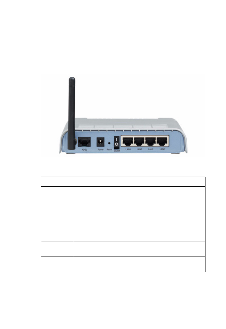
Figure 2-1. Rear Panel
Item Description
ADSL Port WAN port (RJ-45). Connect your ADSL line to this port.
Power Inlet Connect the included power adapter to this inlet.
Warning: Using the wrong type of power adapter may damage
the Barricade.
Reset Button Use this button to reset the power and restore the default
factory settings. To reset without losing configuration settings,
see “Reset” on page 4-82.
On/Off
switch
LAN Ports Fast Ethernet ports (RJ-45). Connect devices on your local area
Use this switch to turn the Barricade ON and OFF.
network to these ports (i.e., a PC, hub, or switch).
2-3
Page 22
I
NSTALLATION
LED Indicators
The power and port LED indicators on the top are illustrated by the
following figure and table.
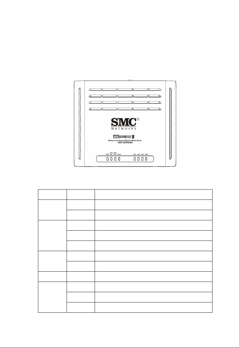
Figure 2-2. Top View
LED Status Description
PWR On The Barricade is receiving power. Normal operation.
Off Power off or failure.
2-4
ADSL
Sync
ADSL
Data
WLAN Flashing The WLAN port is sending or receiving data.
LAN1 to
LAN4
On ADSL connection is functioning correctly.
Flashing The Barricade is establishing an ADSL link.
Off ADSL connection is not established.
Flashing Indicates ADSL port is sending or receiving data.
Off No data is being transferred.
On Ethernet connection is established.
Flashing The indicated LAN port is sending or receiving data.
Off There is no LAN connection on the port.
Page 23

ISP Settings
Please collect the following information from your ISP before setting up
the Barricade:
• ISP account user name and password
• Protocol, encapsulation and VPI/VCI circuit numbers
•DNS server address
• IP address, subnet mask and default gateway (for fixed IP users only)
Connect the System
The Barricade can be positioned at any convenient location in your office
or home. No special wiring or cooling requirements are needed. You
should, however, comply with the following guidelines:
• Keep the Barricade away from any heating devices.
ISP S
ETTINGS
• Do not place the Barricade in a dusty or wet environment.
You should also remember to turn off the power, remove the power cord
from the outlet, and keep your hands dry when you install the Barricade.
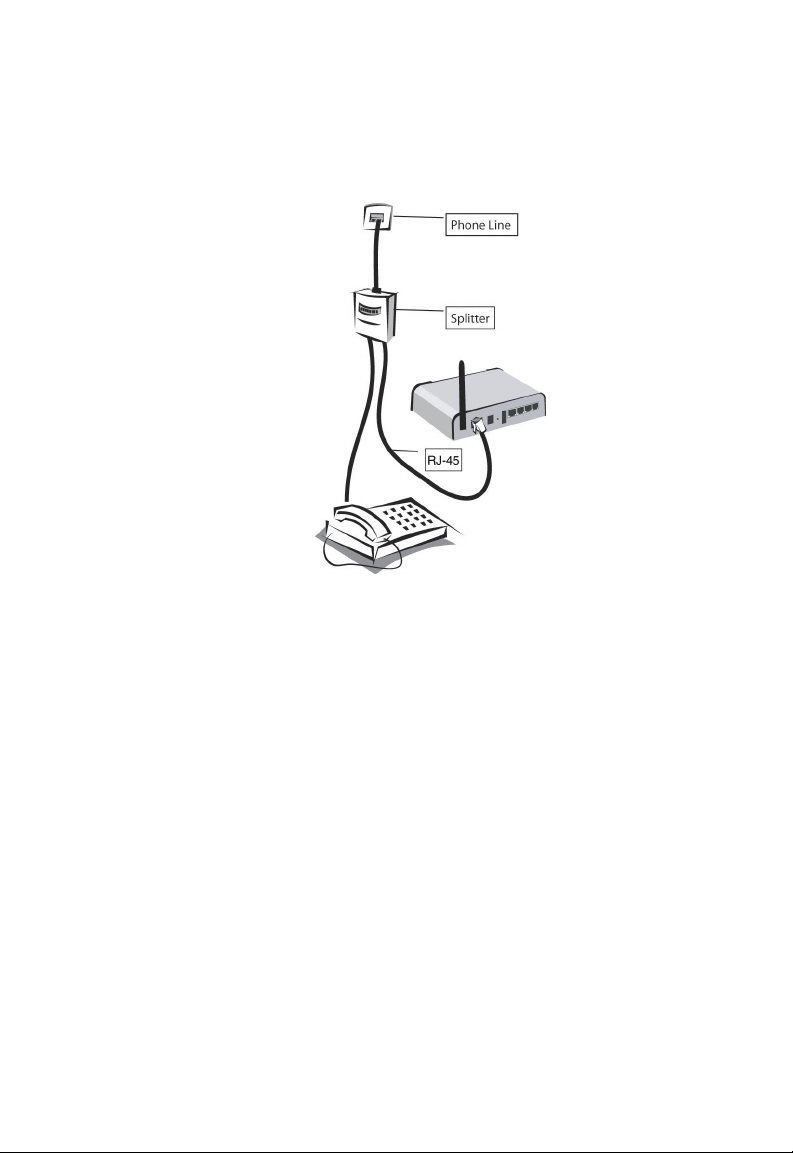
Connecting the ADSL Line
Connect the splitter to the phone line and the phone to the phone port of
the splitter. Using the black RJ-45 cable provided connect the ADSL port
of the Barricade to the ADSL port of the splitter. Refer to the below
illustration.
2-5
Page 24
I
NSTALLATION
The splitter is required for connecting your Barricade and phone to the
same phone line. If you have a dedicated phone line for ADSL connect the
Barricade directly to the phone line.
Note: To prevent high frequency ADSL signals interfering with
telephone calls, each phone must be connected to the same phone
line through a splitter (also known as an ADSL microfilter).
Connecting the network
Using the grey RJ-45 cable provided connect LAN port of the Barricade to
the network card of your computer or other network device, e.g., hub or
switch. The corresponding LAN LED will illuminate green to indicate a
good link.
2-6
Page 25

C
ONNECT THE SYSTEM
Connecting the Power Adapter
Plug the power adapter into the power socket on the rear of the Barricade,
and the other end into a power outlet. Check the power indicator on the
front panel is lit. If the power i
“Troubleshooting” on page A-1.
In case of a power input failure, the Barricade will automatically restart and
begin to operate once the input power is restored.
ndicator is not lit, refer to
Wall Mounting
There are 2 slots on the underside of the Barricade that can be used for
wall mounting. The distance between the 2 slots is 120 mm.
You will need 2 suitable screws, of diameter 4.4 mm, to wall mount the
Barricade.
To wall mount the unit:
1. Determine where you want to mount the Barricade.
2. Drill two holes into the wall. Make sure the holes are 120 mm apart.
3. Insert a screw into each hole, and leave 5 mm of each head exposed.
4. Maneuver the Barricade so the wall-mount slots line up with the two
screws.
5. Place the wall-mount slots over the screws and slide the Barricade
down until the screws fit snugly into the wall-mount slots.
Note: When wall mounting the unit, ensure that it is within reach of the
power outlet.
2-7
Page 26

I
NSTALLATION
2-8
Page 27

C
HAPTER
C
ONFIGURING
After completing hardware setup by connecting all your network devices,
you need to configure your computer to connect to the Barricade.
See:
“Windows 98/Me” on page 3-2
“Windows NT 4.0” on page 3-7
“Windows 2000” on page 3-11
“Windows XP” on page 3-14
or
“Configuring Your Macintosh Computer” on page 3-16
depending on your operating system.
C
LIENT
3
PC
3-1
Page 28
C
ONFIGURING CLIENT
PC
TCP/IP Configuration
To access the Internet through the Barricade, you must configure the
network settings of the computers on your LAN to use the same IP subnet
as the Barricade. The default IP settings for the Barricade are:
IP Address: 192.168.2.1
Subnet Mask: 255.255.255.0
Note: These settings can be changed to fit your network requirements,
but you must first configure at least one computer to access the
Barricade’s web configuration interface in order to make the
required changes. (See “Configuring the ADSL Router” on page
4-1 for instruction on configuring the Barricade.)
Windows 98/Me
You may find that the instructions in this section do not exactly match
your version of Windows. This is because these steps and screen shots
were created from Windows 98. Windows Millennium Edition is similar,
but not identical, to Windows 98.
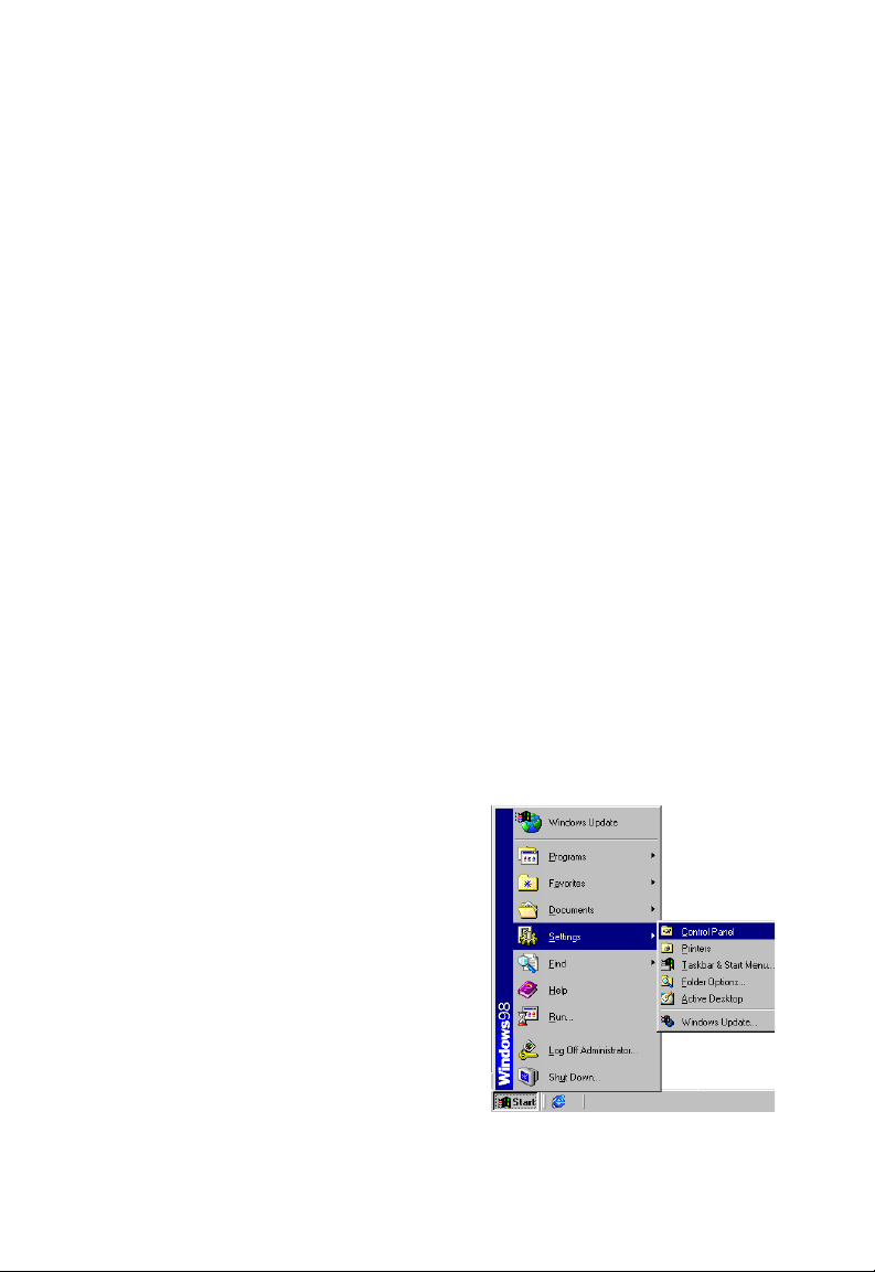
1. On the Windows desktop,
click Start/Settings/Control
Panel.
3-2
Page 29
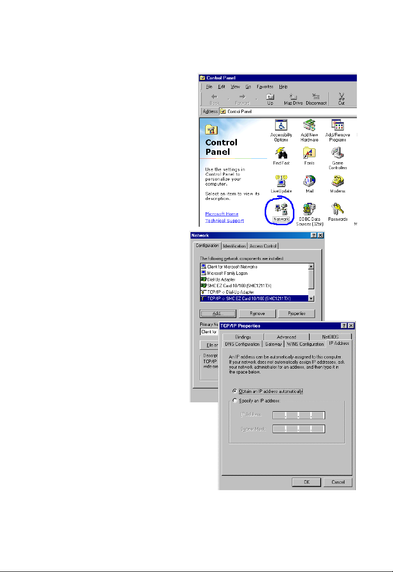
2. In Control Panel,
double-click the Network
icon.
W
INDOWS
98/M
E
3. In the Network window,
under the Configuration
tab, double-click the
TCP/IP item listed for
your network card.
4. In the TCP/IP window,
select the IP Address tab.
If “Obtain an IP
address
automatically” is
already selected, your
computer is already
configured for DHCP. If
not, select this option.
3-3
Page 30
C
ONFIGURING CLIENT
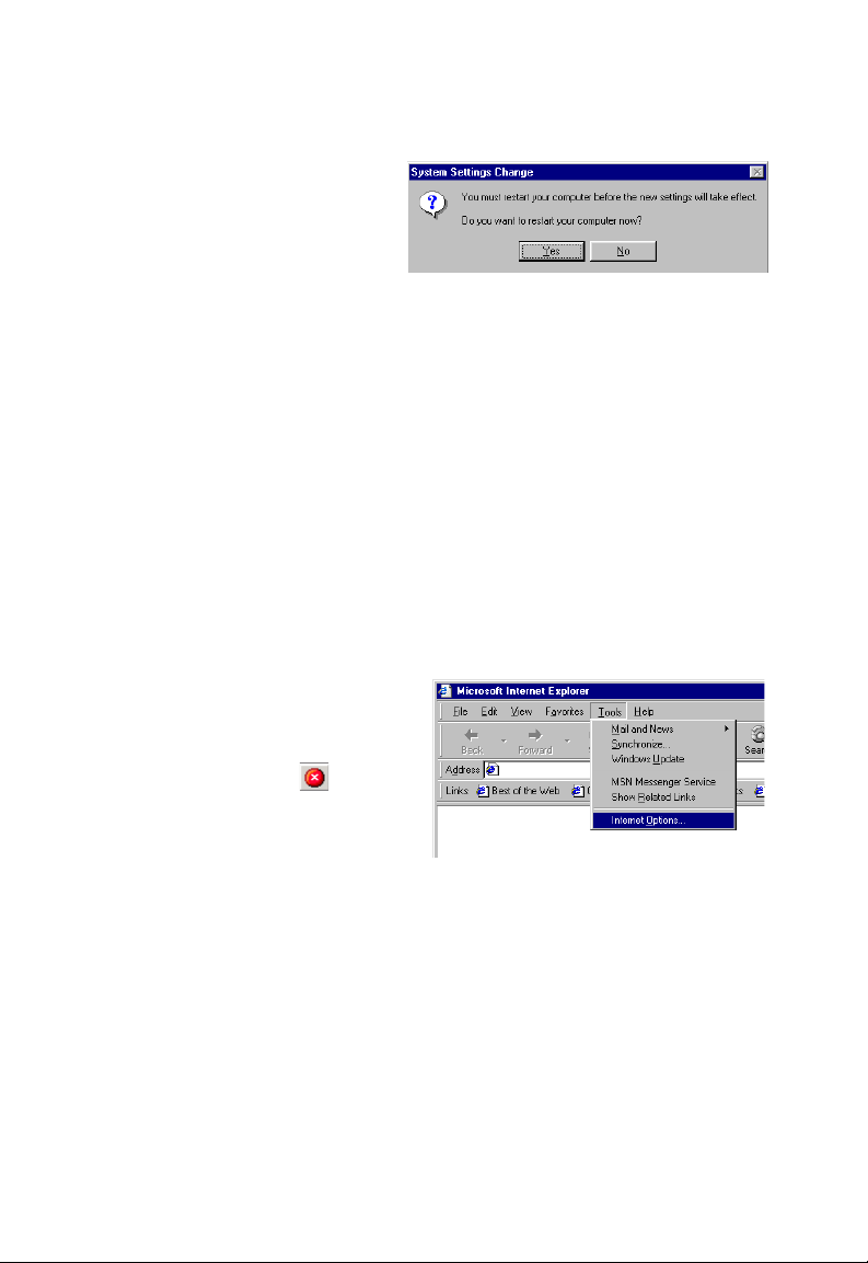
5. Windows may need your
Windows 98/Me CD to
copy some files. After it
finishes copying, it will
prompt you to restart
your system. Click Yes and your computer will restart.
TCP/IP Configuration Setting
Primary DNS Server ____.____.____.____
Secondary DNS Server ____.____.____.____
Default Gateway ____.____.____.____
Host Name ____.____.____.____
PC
Disable HTTP Proxy
You need to verify that the “HTTP Proxy” feature of your web browser is
disabled. This is so that your browser can view the Barricade’s HTML
configuration pages. The following steps are for Internet Explorer.
Internet Explorer
1. Open Internet Explorer.
2. Click the Stop button,
then click Tools/Internet
Options.
3-4
Page 31

3. In the Internet Options
window, click the
Connections tab. Next,
click the LAN Settings...
button.
4. Clear all the check boxes.
5. Click OK, and then click
OK again to close the
Internet Options window.
W
INDOWS
98/M
E
3-5
Page 32
C
ONFIGURING CLIENT
PC
Obtain IP Settings from Your ADSL Router
Now that you have configured your computer to
connect to your Barricade, it needs to obtain new
network settings. By releasing old DHCP IP settings
and renewing them with settings from your Barricade,
you can also verify that you have configured your
computer correctly.
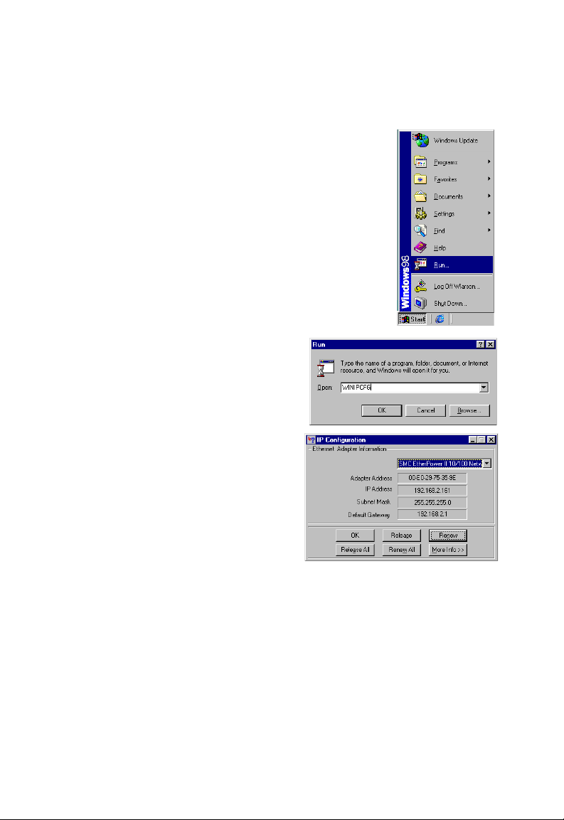
1. On the Windows desktop, click Start/Run...
2. Type “WINIPCFG” and click OK.
It may take a second or two for the
IP Configuration window to
appear.
3. In the IP Configuration window,
select your network card from the
drop-down menu. Click Release
and then click Renew. Verify that
your IP address is now
192.168.2.xxx, your Subnet
Mask is 255.255.255.0 and your
Default Gateway is 192.168.2.1.
These values confirm that your Barricade is functioning. Click OK to
close the IP Configuration window.
3-6
Page 33
Windows NT 4.0
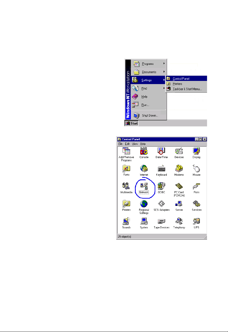
1. On the Windows desktop,
click Start/Settings/
Control Panel.
2. Double-click the
Network icon.
W
INDOWS
NT 4.0
3-7
Page 34
C
ONFIGURING CLIENT
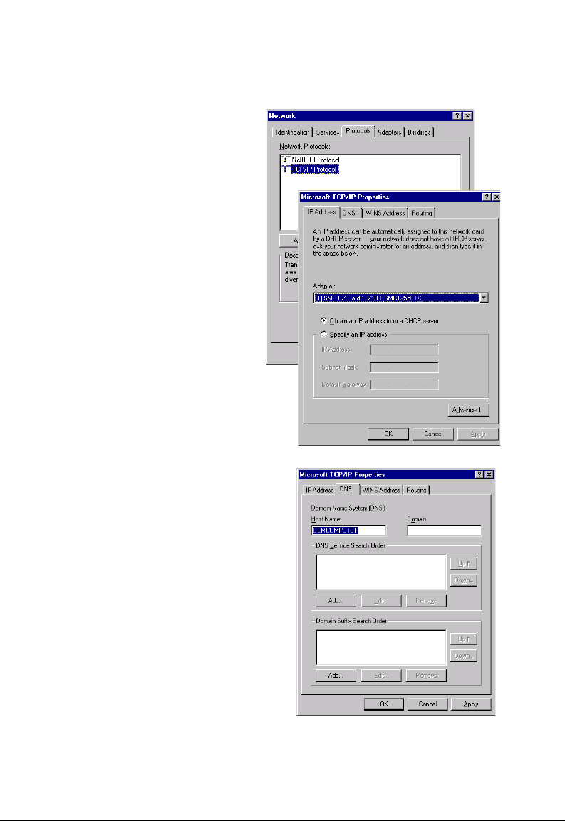
3. In the Network window,
Select the Protocols tab.
Double-click TCP/IP
Protocol.
4. When the Microsoft
TCP/IP Properties
window open, select the
IP Address tab.
5. In the Adapter drop-down
list, be sure your Ethernet
adapter is selected.
6. If “Obtain an IP address
automatically” is already
selected, your computer is
already configured for
DHCP. If not, select this
option and click Apply.
PC
7. Click the DNS tab to see the
primary and secondary DNS
servers. Record these values,
and then click Remove.
Click Apply, and then OK.
3-8
Page 35
W
INDOWS
8. Windows may copy some files, and will then prompt you to restart
your system. Click Yes and your computer will shut down and restart.
TCP/IP Configuration Setting
Default Gateway ____.____.____.____
Primary DNS Server ____.____.____.____
Secondary DNS Server ____.____.____.____
Host Name ____.____.____.____
Disable HTTP Proxy
You need to verify that the “HTTP Proxy” feature of your web browser is
disabled. This is so that your browser can view the Barricade’s HTML
configuration pages. Determine which browser you use and refer to
“Internet Explorer” on page 3-4.
Obtain IP Settings from Your Barricade
Now that you have configured your computer to connect to your
Barricade, it needs to obtain new network settings. By releasing old DHCP
IP settings and renewing them with settings from your Barricade, you will
verify that you have configured your computer correctly.
NT 4.0
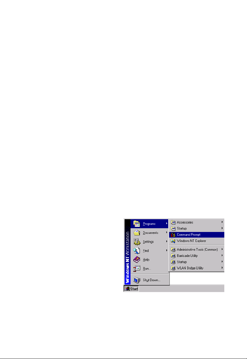
1. On the Windows desktop,
click Start/Programs/
Command Prompt.
3-9
Page 36

C
ONFIGURING CLIENT
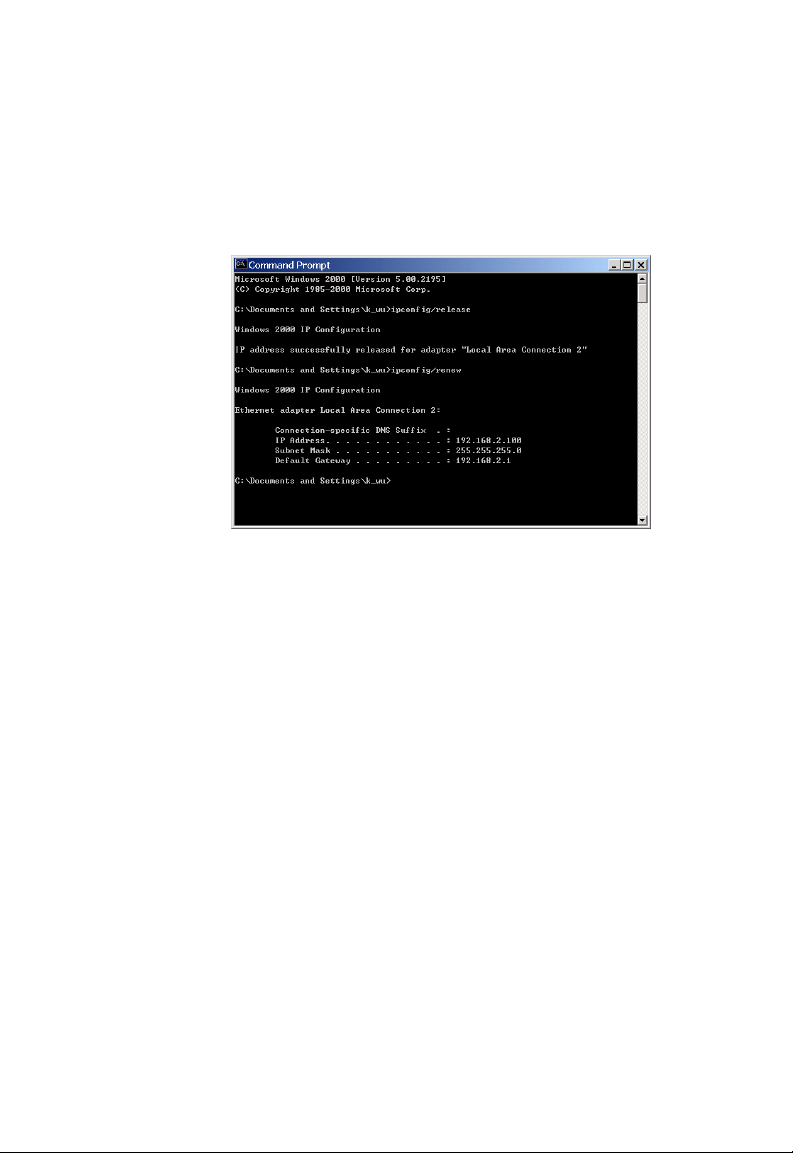
2. In the Command Prompt window, type “IPCONFIG /RELEASE”
and press ENTER.
PC
3. Type “IPCONFIG /RENEW” and press the ENTER key. Verify that
your IP Address is now 192.168.2.xxx, your Subnet Mask is
255.255.255.0 and your Default Gateway is 192.168.2.1. These
values confirm that your Barricade is functioning.
4. Close the Command Prompt window.
Your computer is now configured to connect to the Barricade.
3-10
Page 37

Windows 2000
1. On the Windows desktop, click Start/Settings/Network and
Dial-Up Connections.
2. Click the icon that
corresponds to the
connection to your
Barricade.
3. The connection status
screen will open. Click
Properties.
W
INDOWS
2000
4. Double-click Internet
Protocol (TCP/IP).
5. If “Obtain an IP address
automatically” and
“Obtain DNS server
address automatically” are
already selected, your
computer is already
configured for DHCP. If
not, select this option.
3-11
Page 38

C
ONFIGURING CLIENT
PC
Disable HTTP Proxy
You need to verify that the “HTTP Proxy” feature of your web browser is
disabled. This is so that your browser can view the Barricade’s HTML
configuration pages. Determine which browser you use and refer to
“Internet Explorer” on page 3-4.
Obtain IP Settings from Your Barricade
Now that you have configured your computer to connect to your
Barricade, it needs to obtain new network settings. By releasing old DHCP
IP settings and renewing them with settings from your Barricade, you can
verify that you have configured your computer correctly.
1. On the Windows desktop,
click Start/Programs/
Accessories/
Command Prompt.
2. In the Command Prompt window, type “IPCONFIG/RELEASE”
and press the ENTER key.
3-12
Page 39
W
INDOWS
3. Type “IPCONFIG /RENEW” and press the ENTER key. Verify that
your IP Address is now 192.168.2.xxx, your Subnet Mask is
255.255.255.0 and your Default Gateway is 192.168.2.1. These
values confirm that your ADSL Router is functioning.
4. Close the Command Prompt window.
Your computer is now configured to connect to the Barricade.
2000
3-13
Page 40

C
ONFIGURING CLIENT
PC
Windows XP
1. On the Windows desktop, click Start/Control Panel.
2. In the Control Panel window, click Network and Internet
Connections.
3. The Network Connections window will open. Double-click the
connection for this device.
4. On the connection status screen, click Properties.
5. Double-click Internet Protocol (TCP/IP).
6. If “Obtain an IP address automatically” and “Obtain DNS server
address automatically” are already selected, your computer is already
configured for DHCP. If not, select this option.
Disable HTTP Proxy
You need to verify that the “HTTP Proxy” feature of your web browser is
disabled. This is so that your browser can view the Barricade’s HTML
configuration pages. Determine which browser you use and refer to
“Internet Explorer” on page 3-4.
Obtain IP Settings from Your Barricade
Now that you have configured your computer to connect to your
Barricade, it needs to obtain new network settings. By releasing old DHCP
IP settings and renewing them with settings from your Barricade, you can
verify that you have configured your computer correctly.
1. On the Windows desktop, click Start/Programs/Accessories/
Command Prompt.
3-14
Page 41

W
INDOWS
2. In the Command Prompt window, type “IPCONFIG/RELEASE”
and press the ENTER key.
3. Type “IPCONFIG /RENEW” and press the ENTER key. Verify that
your IP Address is now 192.168.2.xxx, your Subnet Mask is
255.255.255.0 and your Default Gateway is 192.168.2.1. These
values confirm that your ADSL router is functioning.
4. Close the Command Prompt window.
Your computer is now configured to connect to the Barricade.
XP
3-15
Page 42

C
ONFIGURING CLIENT
PC
Configuring Your Macintosh Computer
You may find that the instructions here do not exactly match your
operating system. This is because these steps and screenshots were created
using Mac OS 10.2. Mac OS 7.x and above are similar, but may not be
identical to Mac OS 10.2.
Follow these instructions:
1. Pull down the Apple Menu . Click
System Preferences.
2. Double-click the Network icon in
the Systems Preferences window.
3-16
Page 43

C
ONFIGURING YOUR MACINTOSH COMPUTER
3. If “Using DHCP Server” is
already selected in the
Configure field, your
computer is already
configured for DHCP. If
not, select this Option.
4. Your new settings are shown on the TCP/IP tab. Verify that your IP
Address is now 192.168.2.xxx, your Subnet Mask is
255.255.255.0 and your Default Gateway is 192.168.2.1. These
values confirm that your Barricade is functioning.
5. Close the Network window.
Now your computer is configured to connect to the Barricade.
Disable HTTP Proxy
You need to verify that the “HTTP Proxy” feature of your web browser is
disabled. This is so that your browser can view the Barricade’s HTML
configuration pages. The following steps are for Internet Explorer.
Internet Explorer
1. Open Internet Explorer and click the Stop
button. Click Explorer/Preferences.
2. In the Internet Explorer Preferences window,
under Network, select Proxies.
3-17
Page 44

C
ONFIGURING CLIENT
3. Uncheck all check boxes and click OK.
PC
3-18
Page 45

C
HAPTER
C
ONFIGURING THE
4
ADSL R
After you have configured TCP/IP on a client computer, you can
configure the Barricade using your web browser. Internet Explorer 5.5 or
above, Netscape Navigator, Mozilla, Firefox and Opera are supported.
To access the management interface, enter the default IP address of the
Barricade in your web browser: http://192.168.2.1.
Enter the default password: “smcadmin”, and click LOGIN.
Note: Passwords can contain from 3~12 alphanumeric characters and
are case sensitive.
OUTER
4-1
Page 46

C
ONFIGURING THE
ADSL R
OUTER
Navigating the Management Interface
On initial configuration the first screen is Country Selection. Select your
country from drop down list. This configures the correct channels for the
wireless AP.
Note: The Country Selection screen only appears on initial configuration
or when the Barricade is reset to factory defaults.
You will then see the Status screen appear. For details of this screen, please
refer to page 4-83 of the manual.
4-2
Page 47

N
AVIGATING THE MANAGEMENT INTERFACE
The Setup Wizard is located on the top of the left hand side. Use the Setup
Wizard for quick and easy configuration of your Internet connection and
basic wireless settings. Go to “Setup Wizard” on page 4-4 for details.
MAKING CONFIGURATION CHANGES
Configurable parameters have a dialog box or a drop-down menu. Once a
configuration change has been made on a screen, click the APPLY,
SAVE SETTINGS or NEXT button on the screen to enable the new
setting.
Note: To ensure proper screen refresh after a command entry, be sure
that Internet Explorer 5.5 is configured as follows: Under the
menu Tools/Internet Options/General/Temporary Internet
Files/Settings, the setting for “Check for newer versions of stored
pages” should be “Every visit to the page.”
4-3
Page 48
C
ONFIGURING THE
ADSL R
OUTER
Setup Wizard
TIME ZONE
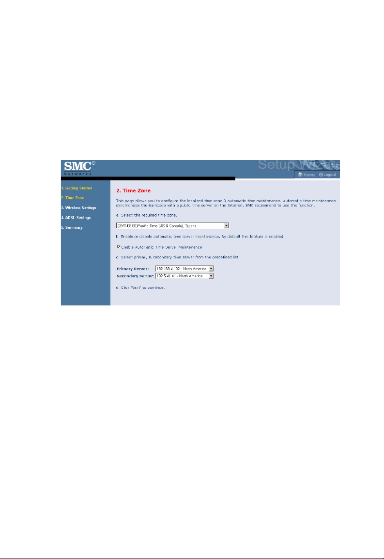
Click on SETUP WIZARD and NEXT, then you will see the Time Zone
screen. Select your local time zone from the drop-down menu. This
information is used for log entries and client filtering.
If you want to automatically synchronize the ADSL router with a public
time server, check the box to Enable Automatic Time Server Maintenance.
Select the desired servers from the drop-down menu.
Click NEXT to continue.
4-4
Page 49

S
Wireless Settings
This screen allows you to configure the SSID, wireless Mode and channel.
Optionally you can disable broadcasting of SSID for added security. SSID
is the name given to your wireless LAN. Wireless clients within the same
network should be configured to use the same SSID.
Parameter Description
SSID Service Set ID. The SSID must be the same on the Barricade
and all of its wireless clients.
SSID Broadcast Enable or disable the broadcasting of the SSID.
Wireless Mode This device supports both 11g and 11b wireless networks. Make
your selection depending on the type of wireless network that
you have.
Channel The radio channel used by the wireless router and its clients to
communicate with each other. This channel must be the same
on the Barricade and all of its wireless clients.
The Barricade will automatically assign itself a radio channel, or
you may select one manually.
ETUP WIZARD
Click NEXT to continue.
4-5
Page 50
C
ONFIGURING THE
ADSL R
OUTER
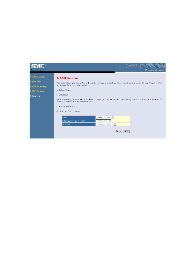
ADSL Settings
Select your Country and Internet Service Provider. This will automatically
configure the Barricade with the correct Protocol, Encapsulation and
VPI/VCI settings for your ISP.
If your Country or Internet Service Provider is not listed in this screen,
you will need to manually enter the settings. Go to “ADSL Settings Country or ISP Not Listed” on page 4-9 in the manual for details.
If your ISP uses Protocols PPPoA or PPPoE you will need to enter the
username and password supplied by your ISP.
If your ISP uses Protocol RFC1483 Routed you will need to enter the IP
address, subnet mask, default gateway and DNS server address supplied by
your ISP.
Click NEXT to continue.
4-6
Page 51

Summary
This screen shows a summary of the configuration parameters that you
have made using the Setup Wizard.
S
ETUP WIZARD
Parameter Description
Wireless Parameters
SSID This is the name of your wireless network.
SSID Broadcast Broadcasting of your SSID is on/off.
Wireless Mode 802.11b only, 802.11g only or mixed mode.
Channel The radio channel used for wireless communication.
Time Zone Parameters
Time Zone The time zone that you selected.
NTP Network Time Protocol is enabled/disabled.
Primary Server The time server that you selected, when Automatic Time
Server Maintenance is enabled.
Secondary Server The time server that you selected, when Automatic Time
Server Maintenance is enabled.
4-7
Page 52

C
ONFIGURING THE
Parameter Description
ADSL Operation Mode
(WAN)
ISP The type of ISP you have selected.
Protocol Indicates the protocol used.
VPI/VCI Virtual Path Identifier (VPI) and Virtual Circuit Identifier
AAL5 Encapsulation Shows the packet encapsulation type. Go to page 4-23 for
Network Layer
Parameters (WAN)
IP Address WAN IP address (only displayed if you have static IP).
Subnet Mask WAN subnet mask (only displayed if you have static IP).
Default Gateway WAN gateway (only displayed if you have static IP).
DNS Server The IP address of the DNS server.
ISP Parameters
Username The ISP assigned user name.
Password The password (hidden).
ADSL R
OUTER
(VCI).
a detailed description.
If the parameters are correct, click Finish to save these settings.
Your Barricade is now set up. Go to “Troubleshooting” on page A-1 if you
cannot make a connection to the Internet.
4-8
Page 53

S
ADSL Settings - Country or ISP Not Listed
If your Country or Internet Service Provider is not listed, select Others.
This will allow you to manually configure your ISP settings. For manual
configuration you will need to know the Protocol, DNS Server,
Encapsulation and VPI/VCI settings used by your ISP. If you have a Static
IP address you will also need to know the IP address, Subnet Mask and
Gateway address. Please contact your ISP for these details.
After selecting “Others” you will need to select what Protocol your ISP
uses from the drop-down menu.
ETUP WIZARD
4-9
Page 54

C
ONFIGURING THE
ADSL R
OUTER
PPPoE
Parameter Description
VPI/VCI Enter the Virtual Path Identifier (VPI) and Virtual
Circuit Identifier (VCI) supplied by your ISP.
Encapsulation Select the encapsulation used by your ISP from the
drop-down menu.
Username Enter user name.
Password Enter password.
Confirm Password Confirm password
Click NEXT to continue.
Go to “Summary” on page 4-7 in the manual for details about the settings.
4-10
Page 55
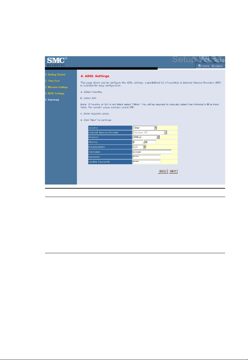
S
ETUP WIZARD
PPPoA
Parameter Description
VPI/VCI Enter the Virtual Path Identifier (VPI) and Virtual
Circuit Identifier (VCI) supplied by your ISP.
Encapsulation Select the encapsulation used by your ISP from the
drop-down menu.
Username Enter user name.
Password Enter password.
Confirm Password Confirm password
Click NEXT to continue.
Go to “Summary” on page 4-7 in the manual for details about the settings.
4-11
Page 56

C
ONFIGURING THE
ADSL R
OUTER
1483 Bridging-DHCP
Parameter Description
DNS Server Domain Name Servers are used to map a domain name
(e.g., www.somesite.com) to the equivalent numerical
IP address. Your ISP should provide the IP address of
a Domain Name Server. Enter the address here.
VPI/VCI Enter the Virtual Path Identifier (VPI) and Virtual
Encapsulation Select the encapsulation used by your ISP from the
Circuit Identifier (VCI) supplied by your ISP.
drop-down menu.
Click NEXT to continue.
Go to “Summary” on page 4-7 in the manual for details about the settings.
4-12
Page 57

S
ETUP WIZARD
1483 Bridging-Static
Parameter Description
IP Address Enter your ISP supplied static IP address here.
Subnet Mask Enter the subnet mask address provided by your ISP.
Default Gateway Enter the gateway address provided by your ISP.
DNS Server Enter the Domain Name Server address.
VPI/VCI Enter the Virtual Path Identifier (VPI) and Virtual
Circuit Identifier (VCI) supplied by your ISP.
Encapsulation Select the encapsulation used by your ISP from the
drop-down menu.
Click NEXT to continue.
Go to “Summary” on page 4-7 in the manual for details about the settings.
4-13
Page 58

C
ONFIGURING THE
ADSL R
OUTER
1483 Routing
Parameter Description
IP Address Enter the IP address provided by your ISP.
Subnet Mask Enter the subnet mask address provided by your ISP.
Default Gateway Enter the gateway address provided by your ISP.
DNS Server Enter the Domain Name Server address.
VPI/VCI Enter the Virtual Path Identifier (VPI) and Virtual
Encapsulation Select the encapsulation used by your ISP from the
Circuit Identifier (VCI) supplied by your ISP.
drop-down menu.
Click NEXT to continue.
Go to “Summary” on page 4-7 in the manual for details about the settings.
4-14
Page 59
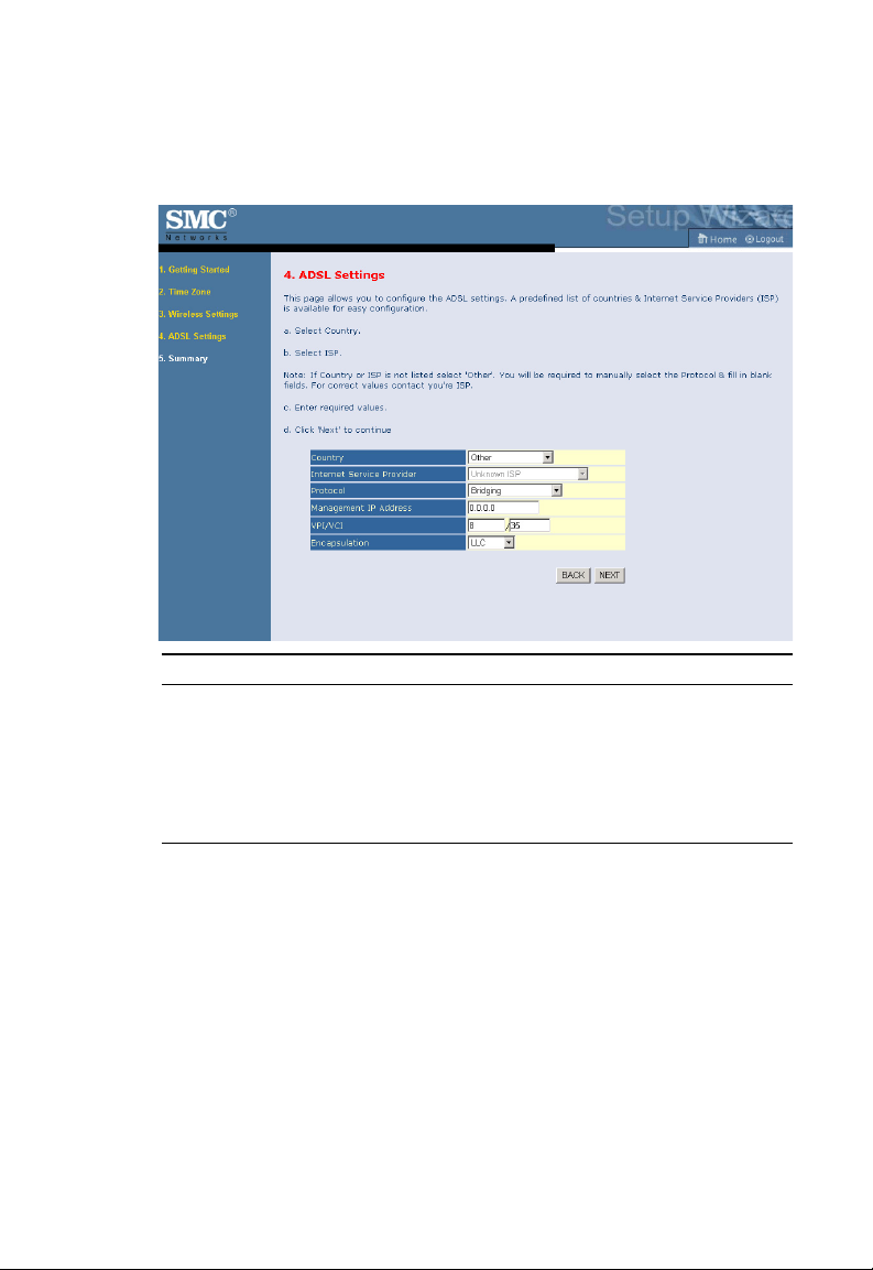
S
ETUP WIZARD
Bridging
Parameter Description
Management IP Address This is the management IP address of the
Barricade.
VPI/VCI Enter the Virtual Path Identifier (VPI) and Virtual
Circuit Identifier (VCI) supplied by your ISP.
Encapsulation Select the encapsulation used by your ISP from the
drop-down menu.
Click NEXT to continue.
Go to “Summary” on page 4-7 in the manual for details about the settings.
4-15
Page 60

C
ONFIGURING THE
ADSL R
OUTER
1483 Routing-DHCP
Parameter Description
DNS Server Enter the Domain Name Server address.
VPI/VCI Enter the Virtual Path Identifier (VPI) and Virtual
Circuit Identifier (VCI) supplied by your ISP.
Encapsulation Select the encapsulation used by your ISP from the
drop-down menu.
Click NEXT to continue.
Go to “Summary” on page 4-7 in the manual for details about the settings.
4-16
Page 61

C
ONFIGURATION PARAMETERS
Configuration Parameters
The left-hand side displays the main menu and the right-hand side shows
descriptive information. There are 14 main menu items as described in the
following table.
Menu Description
System Sets the local time zone, the password for administrator access, and
WAN Specifies the Internet connection settings.
LAN Sets the TCP/IP configuration for the Barricade LAN interface
Wireless Configures the radio frequency, SSID, and security for wireless
NAT Configures Address Mapping, virtual server and special
Routing Sets the routing parameters and displays the current routing table.
Firewall Configures a variety of security and specialized functions including:
SNMP Community string and trap server settings.
UPnP Enables the Universal Plug and Play function.
the IP address of a PC that will be allowed to manage the Barricade
remotely.
and DHCP clients.
communications.
applications.
Access Control, URL blocking, Internet access control scheduling,
intruder detection, and DMZ.
4-17
Page 62

C
ONFIGURING THE
Menu Description
QoS Allows you to prioritize your network traffic.
ADSL Sets the ADSL operation type and shows the ADSL status.
DDNS Configures Dynamic DNS function.
Tools Contains options to ping network connection, trace route, backup
Status Provides WAN connection type and status, firmware and hardware
ADSL R
& restore the current configuration, restore all configuration
settings to the factory defaults, update system firmware, or reset the
system.
version numbers, system IP settings, as well as DHCP, NAT, and
firewall information. Displays the number of attached clients, the
firmware versions, the physical MAC address for each media
interface, and the hardware version and serial number. Shows the
security and DHCP client log.
OUTER
4-18
Page 63

C
ONFIGURATION PARAMETERS
SYSTEM
Time Zone
Select your local time zone from the drop-down menu. This information is
used for log entries and client filtering.
If daylight savings is applied in your area, check the box to Enable
Daylight Savings. Select the start/end dates.
If you want to automatically synchronize the ADSL router with a public
time server, check the box to Enable Automatic Time Server
Maintenance. Select the desired servers from the drop-down menu.
4-19
Page 64
C
ONFIGURING THE
ADSL R
OUTER
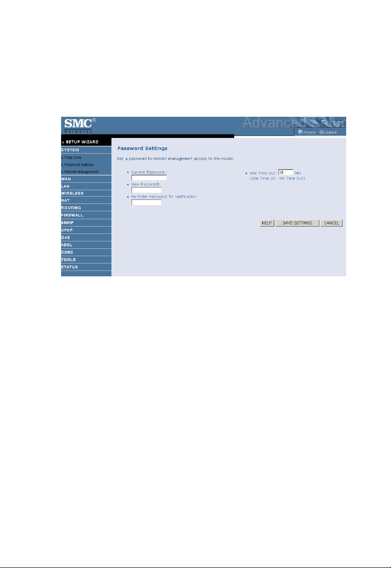
Password Settings
Use this screen to change the password for accessing the management
interface.
Passwords can contain from 3~12 alphanumeric characters and are case
sensitive.
Note: If you lost the password, or you cannot gain access to the user
interface, press the blue reset button on the rear panel, holding it
down for at least five seconds to restore the factory defaults. The
default password is “smcadmin”.
Enter a maximum Idle Time Out (in minutes) to define a maximum period
of time for which the login session is maintained during inactivity. If the
connection is inactive for longer than the maximum idle time, it will
perform system logout, and you have to log in again to access the
management interface. (Default: 10 minutes)
4-20
Page 65

C
ONFIGURATION PARAMETERS
Remote Management
By default, management access is only available to users on your local
network. However, you can also manage the Barricade from a remote host
by entering the IP address of a remote computer on this screen. Check the
Enabled check box, and enter the IP address of the remote host and click
SAVE SETTINGS.
Note: If you check Enabled and specify an IP address of 0.0.0.0, any
remote host can manage the Barricade.
For remote management via WAN IP address you need to connect using
port 8080. Simply enter WAN IP address followed by:8080, for example,
211.20.16.1:8080.
4-21
Page 66

C
ONFIGURING THE
ADSL R
OUTER
WAN
Specify the WAN connection parameters provided by your Internet
Service Provider (ISP).
The following three items are configurable:
•ATM PVC
• Clone MAC
•DNS
4-22
Page 67
C
ONFIGURATION PARAMETERS
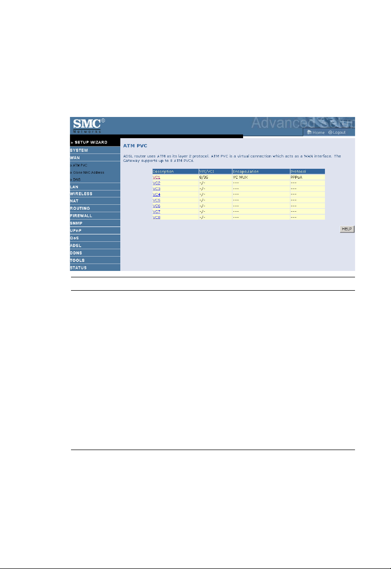
ATM PVC
Enter the ATM (Asynchronous Transfer Mode) virtual connection
parameters here.
Parameter Description
VC1 - VC8 Click on the desired VC to set the values for the connection.
In most cases you ISP will provide a single VC. For single
VC use VC1.
VPI/VCI Displays Virtual Path Identifier (VPI) and Virtual Circuit
Identifier (VCI) configured for corresponding VC.
Encapsulation Displays Encapsulation configured for corresponding VC.
• VC-MUX: Point-to-Point Protocol over ATM Virtual
Circuit Multiplexer (null encapsulation) allows only
one protocol running per virtual circuit with less
overhead.
• LLC: Point-to-Point Protocol over ATM Logical Link
Control (LLC) allows multiple protocols running over
one virtual circuit (using slightly more overhead).
Protocol Displays protocol configured for corresponding VC.
4-23
Page 68
C
ONFIGURING THE
ADSL R
OUTER
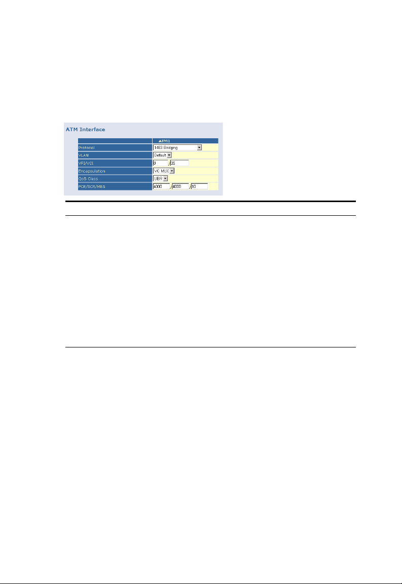
ATM Interface
1483 Bridging
Enter the Bridging settings provided by your ISP.
Parameter Description
VLAN Select VLAN group from the drop-down menu.
New VLAN groups can be created from the LAN
menu.
VPI/VCI Enter the Virtual Path Identifier (VPI) and Virtual
Circuit Identifier (VCI) supplied by your ISP.
Encapsulation Select the encapsulation used by ISP from the
drop-down menu.
QoS Class ATM QoS classes including CBR, UBR and VBR
PCR/SCR/MBS QoS Parameters - PCR (Peak Cell Rate), SCR
(Sustainable Cell Rate) and MBS (Maximum Burst
Size) are configurable.
4-24
Page 69

C
ONFIGURATION PARAMETERS
PPPoA
Parameter Description
VPI/VCI Enter the Virtual Path Identifier (VPI) and Virtual Circuit
Identifier (VCI) supplied by your ISP.
Encapsulation Select the encapsulation used by ISP from the drop-down
menu.
QoS Class ATM QoS classes including CBR, UBR and VBR.
PCR/SCR/MBS QoS Parameters - PCR, SCR and MBS are configurable.
IP assigned by ISP Select Yes if you have a dynamic IP address. Select No if
IP Address Enter the IP address provided by your ISP. For dynamic
Subnet Mask Enter the subnet mask address provided by your ISP. For
Connect Type Sets connection mode to Always connected,
Idle Time (Minute) Enter the maximum idle time for the Internet connection.
Username Enter the user name provided by your ISP.
Password Enter the password provided by your ISP.
you have a static IP address.
IP leave this field blank.
dynamic IP leave this field blank.
Auto-Triggered by traffic or Manual connection. For flat
rate services use Always connected.
After this time has been exceeded the connection will be
terminated. This setting only applies when the Connect
Type is set to Auto-Triggered by traffic.
4-25
Page 70
C
ONFIGURING THE
Parameter Description
Confirm Password Confirm password.
MTU Leave the Maximum Transmission Unit (MTU) at the
ADSL R
OUTER
default value unless instructed by your ISP.
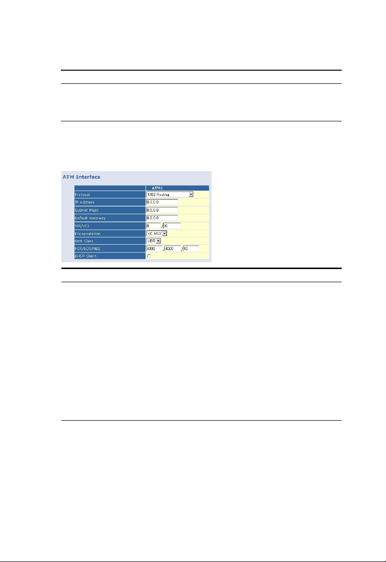
1483 Routing
Parameter Description
IP Address Enter the IP address provided by your ISP.
Subnet Mask Enter the subnet mask address provided by your ISP.
Default Gateway Enter the gateway address provided by your ISP.
VPI/VCI Enter the Virtual Path Identifier (VPI) and Virtual
Circuit Identifier (VCI) supplied by your ISP.
Encapsulation Select the encapsulation used by ISP from the
drop-down menu.
QoS Class ATM QoS classes including CBR, UBR and VBR
PCR/SCR/MBS QoS Parameters - PCR, SCR and MBS are configurable.
DHCP Client Check the box if your ISP assigns an IP address
dynamically.
4-26
Page 71

C
ONFIGURATION PARAMETERS
PPPoE
Parameter Description
VPI/VCI Enter the Virtual Path Identifier (VPI) and Virtual
Circuit Identifier (VCI) supplied by your ISP.
Encapsulation Select the encapsulation used by ISP from the
drop-down menu.
QoS Class ATM QoS classes including CBR, UBR and VBR.
PCR/SCR/MBS QoS Parameters - PCR, SCR and MBS are
configurable.
IP assigned by ISP Select Yes if you have a dynamic IP address. Select
No if you have a static IP address.
IP Address Enter the IP address provided by your ISP. For
dynamic IP leave this field blank.
Subnet Mask Enter the Subnet Mask address provided by your ISP.
For dynamic IP leave this field blank.
Connect Type Sets connection mode to Always connected,
Auto-Triggered by traffic or Manual connection. For
flat rate services use Always connected.
Idle Time (Minute) Enter the maximum idle time for the Internet
connection. After this time has been exceeded the
connection will be terminated. This setting only
applies when the Connect Type is set to
Auto-Triggered by traffic.
Username Enter the user name provided by your ISP.
4-27
Page 72
C
ONFIGURING THE
Parameter Description
Password Enter the password provided by your ISP.
Confirm Password Confirm password.
MTU Leave the Maximum Transmission Unit (MTU) at the
ADSL R
OUTER
default value unless instructed by your ISP.
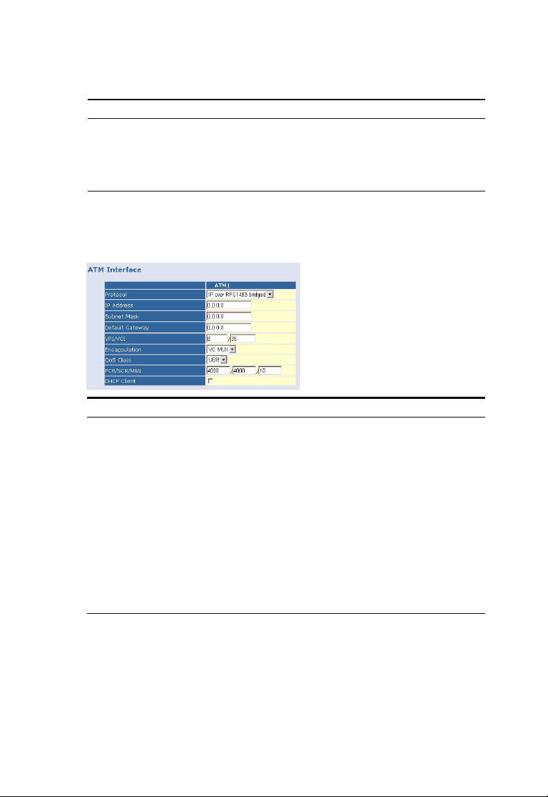
IP over RFC 1483 bridged
Parameter Description
IP Address Enter the IP address provided by your ISP.
Subnet Mask Enter the subnet mask address provided by your ISP.
Default Gateway Enter the gateway address provided by your ISP.
VPI/VCI Enter the Virtual Path Identifier (VPI) and Virtual
Circuit Identifier (VCI) supplied by your ISP.
Encapsulation Select the encapsulation used by ISP from the
drop-down menu.
QoS Class ATM QoS classes including CBR, UBR and VBR.
PCR/SCR/MBS QoS Parameters - PCR, SCR and MBS are configurable.
DHCP Client Check the box if your ISP assigns an IP address
dynamically.
4-28
Page 73

C
ONFIGURATION PARAMETERS
Clone MAC Address
Some ISPs require you to register your MAC address with them. If this is
the case, the MAC address of the Barricade must be changed to the MAC
address that you have registered with your ISP.
4-29
Page 74
C
ONFIGURING THE
ADSL R
OUTER
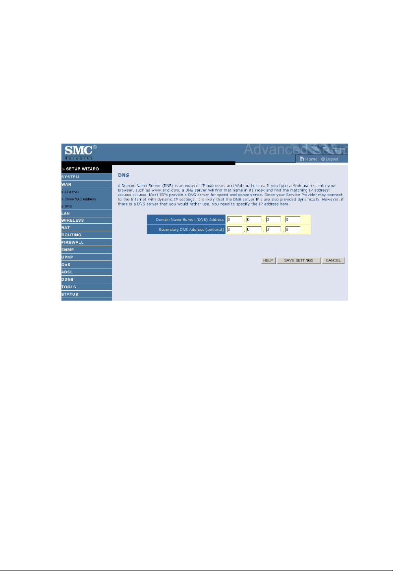
DNS
Domain Name Servers (DNS) are used to map a domain name
(e.g., www.smc.com) with the IP address (e.g., 64.147.25.20). Your ISP
should provide the IP address of one or more Domain Name Servers.
Enter those addresses on this screen, and click SAVE SETTINGS.
4-30
Page 75
C
ONFIGURATION PARAMETERS
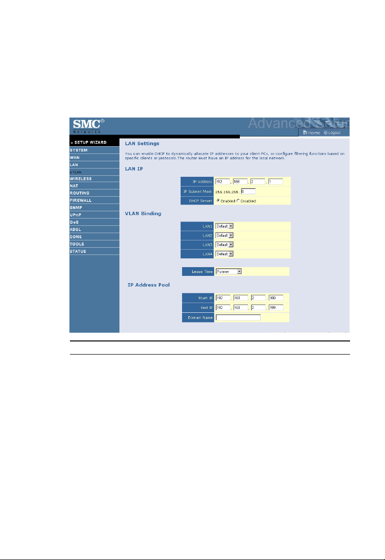
LAN
Use the LAN menu to configure the LAN IP address, VLAN binding and
to enable the DHCP server for dynamic client address allocation.
Parameter Description
LAN IP
IP Address The IP address of the Barricade.
IP Subnet Mask The subnet mask of the network.
DHCP Server Enable or Disable the DHCP server function. By default the
DHCP server is enabled for automatic IP address assignment
to client devices.
VLAN Binding
LAN1 to LAN4 Select VLAN group for the corresponding LAN port. By
default all ports members of the Default VLAN.
Lease Time Set the IP lease time. For home networks this may be set to
Forever, which means there is no time limit on the IP address
lease.
4-31
Page 76

C
ONFIGURING THE
Parameter Description
IP Address Pool
Start IP Address Specify the start IP address of the DHCP pool. Do not include
End IP Address Specify the end IP address of the DHCP pool.
Domain Name If your network uses a domain name, enter it here. Otherwise,
ADSL R
OUTER
the IP address of the Barricade in the client address pool. If you
change the pool range, make sure the first three octets match
the gateway’s IP address, i.e., 192.168.2.xxx.
leave this field blank.
VLAN
VLANs are organized and controlled by VLAN Profiles. Up to 4 VLAN
profiles can be created. Once a VLAN profile is created, you should add
interfaces into the VLAN by changing the VLAN setting of that interface.
Please note that only those interfaces of IEEE 802 bridging type (ex. LAN
ports and 1483 Bridging PVCs) can be added to a VLAN.
4-32
Page 77

C
ONFIGURATION PARAMETERS
Click Add VLAN to setup the profile.
• Description: enter a name or description for the VLAN.
• IP Address: enter the IP address.
• Subnet Mask: enter the subnet mask.
• NAT Domain: select private or public.
• IGMP Snooping: Internet Group Management Protocol (IGMP)
snooping is a method by which Layer 2 devices can “listen in” on
IGMP conversations between hosts and routers. When a switch hears
a group join message from a host, it notes which switch interface it
heard the message on, and adds that interface to the group. Similarly,
when a Layer 2 switch hears a group leave message or a response timer
expires, the switch will remove that host’s switch interface from the
group.
• IGMP Querier: if the IGMP Querier is enabled, then the router will
periodically query all multicast group members on the specified
VLAN.
4-33
Page 78

C
ONFIGURING THE
ADSL R
OUTER
WIRELESS
The Barricade also operates as a wireless access point, allowing wireless
computers to communicate with each other. To configure this function, all
you need to do is enable the wireless function, define the radio channel,
the SSID, and the security options. Check Enable and click SAVE
SETTINGS.
4-34
Page 79

C
ONFIGURATION PARAMETERS
Channel and SSID
You must specify a common radio channel and SSID (Service Set ID) to
be used by the Barricade and all of its wireless clients. Be sure you
configure all of its clients to the same values.
Parameter Description
SSID Service Set ID (SSID) is the name given to the wireless network.
The SSID must be the same on the Barricade and all of its
wireless clients.
SSID Broadcast Enable or disable the broadcasting of the SSID. Disabling
broadcasting of the SSID provides added security by hiding
your wireless network.
Wireless Mode This device supports both 11g and 11b wireless networks. Make
your selection depending on the type of wireless network that
you have.
Channel The radio channel used by the wireless router and its clients to
communicate with each other. This channel must be the same
on the Barricade and all of its wireless clients.
The Barricade will automatically assign itself a radio channel, or
you may select one manually.
4-35
Page 80

C
ONFIGURING THE
ADSL R
OUTER
Access Control
Using the Access Control functionality, you can restrict access based on
MAC address. Each PC has a unique identifier known as a Medium Access
Control (MAC) address. With MAC filtering enabled, the computers
whose MAC address you have listed in the filtering table will be able to
connect (or will be denied access) to the Barricade.
• Enable MAC Filtering: select to turn on/off this feature.
• Access Rule for registered MAC address: select to allow/deny access
for the registered MAC addresses. Selecting Allow means only MAC
addresses registered here will be able to connect to the router.
Selecting Deny means only the MAC addresses registered here will be
denied access to the router.
• MAC Address Filtering List: you can use the drop-down menu to select
and quickly copy the entry to the MAC Filtering table.
4-36
Page 81
C
ONFIGURATION PARAMETERS
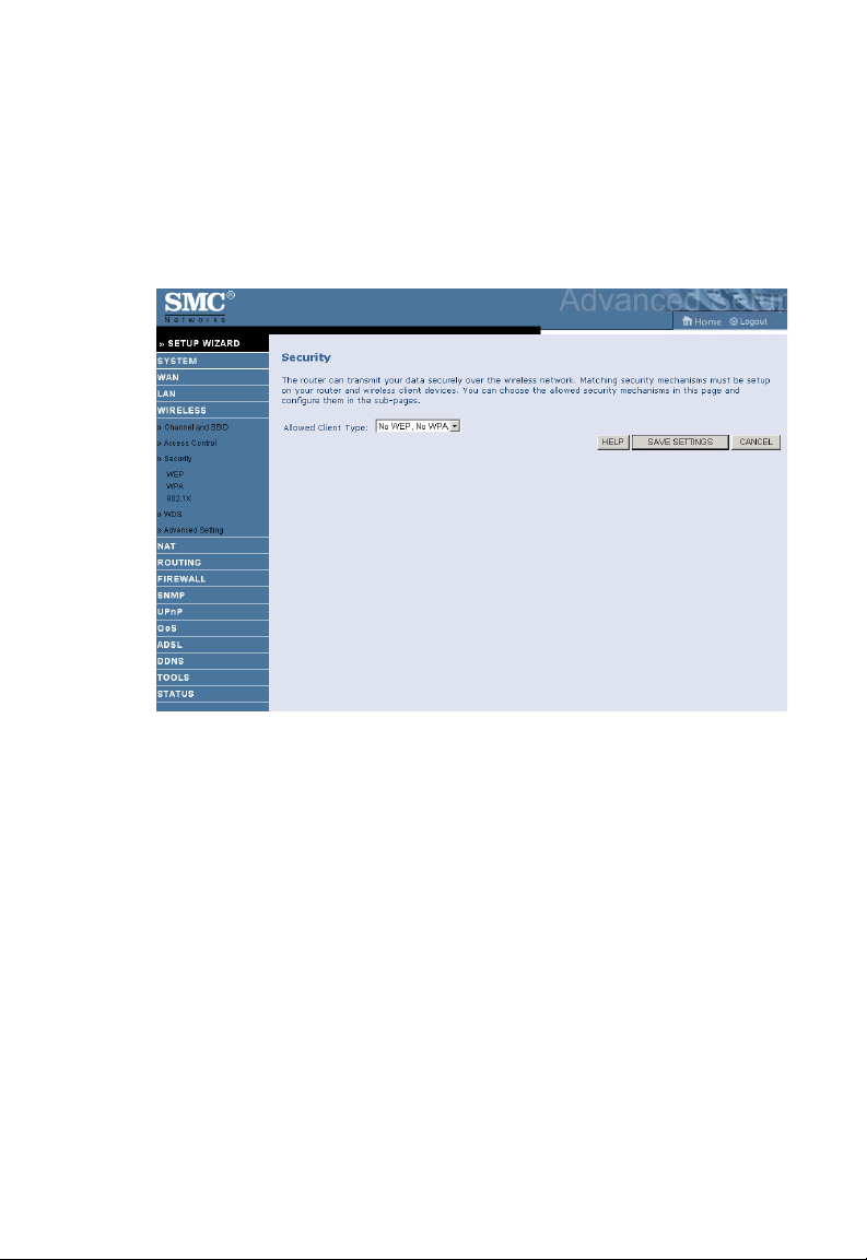
Security
To make your wireless network safe, you should turn on the security
function. The Barricade supports WEP (Wired Equivalent Privacy), WPA
(Wi-Fi Protected) and WPA2 security mechanisms.
Three options are available:
• No WEP, No WPA
• WEP only
• WPA only
4-37
Page 82

C
ONFIGURING THE
ADSL R
OUTER
WEP
If you want to use WEP to protect your wireless network, you need to set
the same parameters for the Barricade and all your wireless clients.
Parameter
WEP Mode Select 64-bit or 128-bit key to use for encryption.
Key Entry Method Select Hex or ASCII to use for encryption key
Key Provisioning Select Static if there is only one fixed key for encryption. If
you want to select Dynamic, you would need to enable
802.1X function first.
Description
You can automatically generate encryption keys using the passphrase or
manually enter the keys. To generate the keys automatically enter a
passphrase and click GENERATE. Select the default key from the
drop-down menu and click SAVE SETTINGS.
Note: Before saving settings the key is shown in clear text. If you wireless
client does not have a passphrase utility make a note of the default
4-38
Page 83

C
ONFIGURATION PARAMETERS
key before saving settings. This is so you can configure your
wireless client with the correct key.
To manually configure the encryption key, enter five hexadecimal pairs of
digits for each 64-bit key, or enter 13 pairs for the single 128-bit key.
(A hexadecimal digit is a number or letter in the range 0-9 or A-F.)
Note that WEP protects data transmitted between wireless nodes, but
does not protect any transmissions over your wired network or over the
Internet.
Note: The passphrase can consist of up to 32 alphanumeric characters.
4-39
Page 84

C
ONFIGURING THE
ADSL R
OUTER
WPA
Wi-Fi Protected Access (WPA) combines temporal key integrity protocol
(TKIP) and 802.1X mechanisms. It provides dynamic key encryption and
802.1X authentication service. The Barricade supports both WPA and
WPA2.
WPA/WPA2 is a security enhancement that strongly increases the level of
data protection and access control for existing wireless LAN. Matching
authentication and encryption methods must be set up on your Barricade
and wireless client devices to use WPA/WPA2. To use WPA, your wireless
network cards must be equipped with software that supports WPA. A
security patch from Microsoft is available for free download (for XP only).
Parameter
WPA mode Select WPA or WPA2 or mixed mode.
Cypher suite The security mechanism used in WPA for encryption.
Description
4-40
Page 85

C
ONFIGURATION PARAMETERS
Parameter
Authentication Choose 802.1X or Pre-shared Key to use as the
authentication method.
•802.1X: for the enterprise network with a RADIUS server.
•Pre-shared key: for the SOHO network environment
without an authentication server.
Pre-shared
key type
Pre-shared Key Type in the key here.
Group Key
Re_Keying
Select the key type to be used in the Pre-shared Key.
The period of renewing broadcast/multicast key.
Description
4-41
Page 86
C
ONFIGURING THE
ADSL R
OUTER
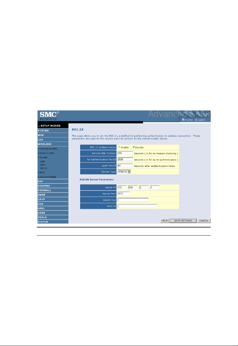
802.1X
If 802.1X is used in your network, then you should enable this function for
the Barricade. Management access will be checked against the
authentication database stored on the Barricade. If an authentication
RADIUS server is used, you must specify the secret key of the
Message-Authenticator attribute, i.e., Message Digest-5 (MD5), and the
corresponding parameters in the RADIUS Server Parameters field for the
remote authentication protocol.
Parameter Description
802.1X
Authentication
Session Idle Timeout Defines a maximum period of time for which the
Re-Authentication
Period
Quiet Period Defines a maximum period of time for which the Barricade
Server Type Select RADIUS as the authentication server.
Enable or disable this authentication function.
connection is maintained during inactivity.
Defines a maximum period of time for which the
authentication server will dynamically re-assign a session
key to a connected client.
will wait between failed authentications.
4-42
Page 87

C
ONFIGURATION PARAMETERS
Parameter Description
RADIUS Server Parameters
Server IP The IP address of your authentication server.
Server Port The port used for the authentication service.
Secret Key The secret key shared between the authentication server
and its clients.
NAS-ID Defines the request identifier of the Network Access
Server.
WDS
The Wireless Distribution System (WDS) provides a means to extend the
range of a Wireless Local Area Network (WLAN). WDS allows an Access
Point (AP) to establish a direct link to other APs and allows stations to
roam freely within the area covered by the WDS.
To refresh the list of available access points, Click Rescan. Available
access points will show up on the AP MAC Address Table, check the box
to add that particular access point to the WDS.
4-43
Page 88

C
ONFIGURING THE
ADSL R
OUTER
Advanced Setting
To change the settings on this screen is recommended for experienced user
only. It is advised to leave the parameters at the default value.
• Beacon Interval: this represents the amount of time between beacon
transmissions. Before a station enters power save mode, the station
needs the beacon interval to know when to wake up to receive the
beacon (and learn whether there are buffered frames at the access
point).
• DTIM Interval: Delivery Traffic Indication Message, indicates when
the DTIM occurs. A DTIM interval is a count of the number of
beacon frames that must occur before the access point sends the
buffered multicast frames. For example, a DTIM interval of one means
that the multicast frames are sent after each beacon frame. A DTIM
interval of two indicates that multicast frames are sent after every two
beacon frames, and so on. Because each beacon frame includes a field
that identifies the DTIM interval, all stations know when to wake up
and receive multicast frames if they are implementing power saving.
4-44
Page 89

C
ONFIGURATION PARAMETERS
• Fragmentation Threshold: this is the maximum size for directed data
packets transmitted. Larger frames fragment into several packets this
size or smaller before transmission. The receiving station then
reassembles the transmitted fragments.
• RTS Threshold: RTS stands for “Request to Send”. This parameter
controls what size data packet the low level RF protocol issues to an
RTS packet. Using a small value causes RTS packets to be sent more
often, consuming more of the available bandwidth, therefore reducing
the apparent throughput of the network packet. However, the more
RTS packets that are sent, the quicker the system can recover from
interference or collisions.
• CTS Protection Mode: CTS stands for “Clear to Send”. If this value is
set to Auto. The AP will automatically use CTS Protection Mode when
the 802.11g products are experiencing severe problems and are not
able to transmit to the AP in an environment with heavy 802.11b
traffic. This function boosts the AP’s ability to catch all 802.11g
transmissions but will decrease the performance.
• WMM Mode: Wireless Multimedia support. WMM prioritizes traffic
according to 4 AC (Access Categories) - voice, video, best effort, and
background. However, it does not provide guaranteed throughput. It
is suitable for simple applications that require QoS, such as Wi-Fi
Voice over IP (VoIP) phone.
4-45
Page 90

C
ONFIGURING THE
ADSL R
OUTER
NAT
Network Address Translation allows multiple users to access the Internet
sharing one public IP.
4-46
Page 91
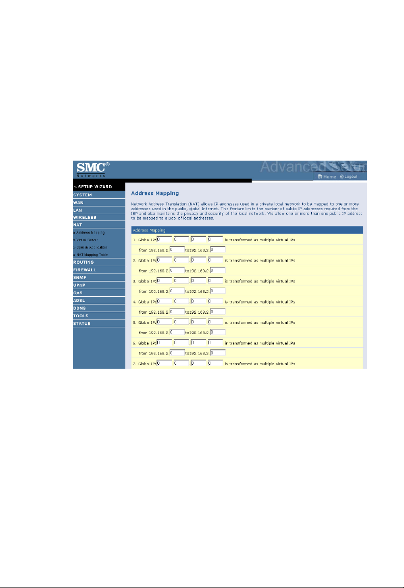
C
ONFIGURATION PARAMETERS
Address Mapping
Allows one or more public IP addresses to be shared by multiple internal
users. This also hides the internal network for increased privacy and
security. Enter the public IP address you wish to share into the Global IP
field. Enter a range of internal IPs that will share the global IP into the
“from” field.
4-47
Page 92

C
ONFIGURING THE
ADSL R
OUTER
Virtual Server
If you configure the Barricade as a virtual server, remote users accessing
services such as web or FTP at your local site via public IP addresses can
be automatically redirected to local servers configured with private IP
addresses. In other words, depending on the requested service (TCP/UDP
port number), the Barricade redirects the external service request to the
appropriate server (located at another internal IP address).
For example, if you set Type/Public Port to TCP/80 (HTTP or web) and
the Private IP/Port to 192.168.2.2/80, then all HTTP requests from
outside users will be transferred to 192.168.2.2 on port 80. Therefore, by
just entering the IP address provided by the ISP, Internet users can access
the service they need at the local address to which you redirect them.
The more common TCP service ports include:
HTTP: 80, FTP: 21, Telnet: 23, and POP3: 110.
A list of ports is maintained at the following link:
http://www.iana.org/assignments/port-numbers.
4-48
Page 93

C
ONFIGURATION PARAMETERS
Special Application
Some applications require multiple connections, such as Internet gaming,
video-conferencing, and Internet telephony. These applications may not
work when Network Address Translation (NAT) is enabled. If you need to
run applications that require multiple connections, use these screens to
specify the additional public ports to be opened for each application.
4-49
Page 94
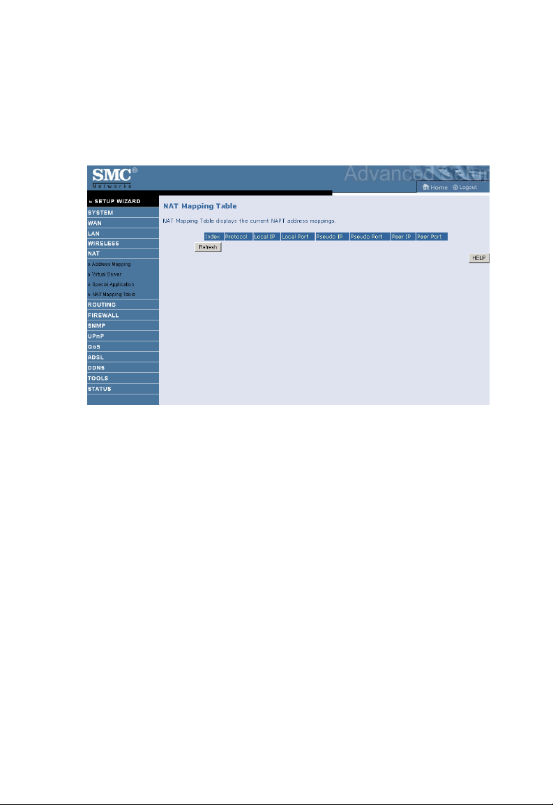
C
ONFIGURING THE
ADSL R
OUTER
NAT Mapping Table
This screen displays the current NAPT (Network Address Port
Translation) address mappings.
4-50
Page 95

C
ONFIGURATION PARAMETERS
ROUTING
These screens define routing related parameters, including static routes and
RIP (Routing Information Protocol) parameters.
Static Route
Parameter Description
Index Check the box of the route you wish to delete or modify.
Network Address Enter the IP address of the remote computer for which
to set a static route.
Subnet Mask Enter the subnet mask of the remote network for which
to set a static route.
Gateway Enter the WAN IP address of the gateway to the remote
network.
Click Add to add a new static route to the list, or check the box of an
already entered route and click Modify. Clicking Delete will remove an
entry from the list.
4-51
Page 96

C
ONFIGURING THE
ADSL R
OUTER
RIP
RIP sends routing-update messages at regular intervals and when the
network topology changes. When a router receives a routing update that
includes changes to an entry, it updates its routing table to reflect the new
route. RIP routers maintain only the best route to a destination. After
updating its routing table, the router immediately begins transmitting
routing updates to inform other network routers of the change.
Parameter Description
General RIP Parameters
RIP mode Globally enables or disables RIP.
Auto summary If Auto summary is disabled, then RIP packets will
Table of current Interface RIP
parameter
Interface The WAN interface to be configured.
4-52
include sub-network information from all subnetworks connected to the router.
If enabled, this sub-network information will be
summarized to one piece of information covering
all sub-networks.
Page 97

C
ONFIGURATION PARAMETERS
Parameter Description
Operation Mode Disable: RIP disabled on this interface.
Enable: RIP enabled on this interface.
Silent: Listens for route broadcasts and updates its
route table. It does not participate in sending route
broadcasts.
Version Sets the RIP (Routing Information Protocol)
version to use on this interface.
Poison Reverse A method for preventing loops that would cause
endless retransmission of data traffic.
Authentication Required • None: No authentication.
• Password: A password authentication key is
included in the packet. If this does not match
what is expected, the packet will be discarded.
This method provides very little security as it
is possible to learn the authentication key by
watching RIP packets.
• MD5 : An algorithm that is used to verif y data
integrity through the creation of a 128-bit
message digest from data input (which may
be a message of any length) that is claimed to
be as unique to that specific data as a
fingerprint is to a specific individual.
Authentication Code Password or MD5 Authentication key.
4-53
Page 98
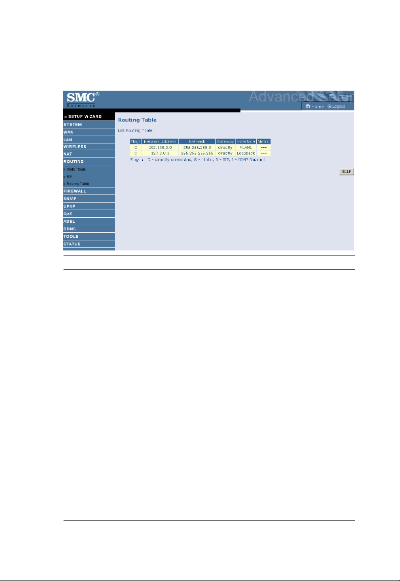
C
ONFIGURING THE
ADSL R
OUTER
Routing Table
Parameter Description
Flags Indicates the route status:
C = Direct connection on the same subnet.
S = Static route.
R = RIP (Routing Information Protocol) assigned route.
I = ICMP (Internet Control Message Protocol) Redirect route.
Network
Address
Netmask The subnetwork associated with the destination.
Gateway The IP address of the router at the next hop to which frames are
Interface The local interface through which the next hop of this route is
Metric When a router receives a routing update that contains a new or
Destination IP address.
This is a template that identifies the address bits in the destination
address used for routing to specific subnets. Each bit that corresponds
to a “1” is part of the subnet mask number; each bit that corresponds
to “0” is part of the host number.
forwarded.
reached.
changed destination network entry, the router adds 1 to the metric
value indicated in the update and enters the network in the routing
table.
4-54
Page 99

C
ONFIGURATION PARAMETERS
FIREWALL
The Barricade Router’s firewall inspects packets at the application layer,
maintains TCP and UDP session information including time-outs and the
number of active sessions, and provides the ability to detect and prevent
certain types of network attacks.
Network attacks that deny access to a network device are called
Denial-of-Service (DoS) attacks. DoS attacks are aimed at devices and
networks with a connection to the Internet. Their goal is not to steal
information, but to disable a device or network so users no longer have
access to network resources.
The Barricade protects against the following DoS attacks: IP Spoofing,
Land Attack, Ping of Death, IP with zero length, Smurf Attack, UDP port
loopback, Snork Attack, TCP null scan, and TCP SYN flooding.
(For details see page 4-62.)
The firewall does not significantly affect system performance, so we advise
leaving it enabled to protect your network. Select Enable and click the
SAVE SETTINGS button to open the Firewall submenus.
4-55
Page 100
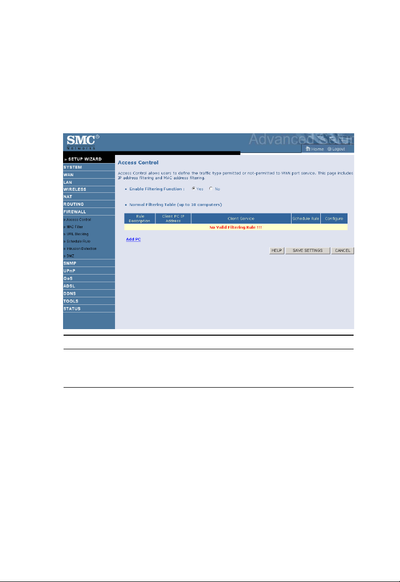
C
ONFIGURING THE
ADSL R
OUTER
Access Control
Access Control allows users to define the outgoing traffic permitted or
not-permitted through the WAN interface. The default is to permit all
outgoing traffic.
Parameter Description
Enable Filtering
Function
Normal Filtering Table Displays a summary of the filtering rules configured.
Click Yes to turn on the filtering function.
4-56
 Loading...