

Page 1
.
ELITECONNECT WLAN SECURITY SYSTEM
♦ Full authentication support—supports RADIUS, LDAP, 802.1x,
Kerberos, Windows NT/2000 domain and built-in database.
♦ VPN support allows secure wireless communications to and from
wireless clients.
♦ Rights-based network access increases network security by
providing network administrators full control on users’ access to a
network, based on user identification, location, and time.
♦ Web-based configuration is easy-to-use, convenient and provides
simple configuration management.
♦ Network access and usage policies can be set for trusted users and
guests by user identification, location, and time.
♦ Roaming across different subnets and persistent session roaming
eliminates the need for re-authentication by roaming users.
User Manual
SMC2504W
SMC2502W
Page 2

Page 3

ELITECONNECT
WLAN SECURITY SYSTEM
USER MANUAL
From SMC’s EliteConnect line of enterprise wireless LAN solutions
38 Tesla March 2002
Irvine, CA 92618 Part No. 01-111343-006
Phone: (949) 679-8000
Page 4

Page 5

Copyrights and Trademarks
Copyright
Information furnished by SMC Networks, Inc. (SMC) is believed to be accurate and
reliable. However, no responsibility is assumed by SMC for its use, nor for any
infringements of patents or other rights of third parties which may result from its
use. No license is granted by implication or otherwise under any patent or patent
rights of SMC. SMC reserves the right to change specifications at any time without
notice.
Copyright © 2002 by SMC Networks, Inc.
38 Tesla
Irvine, CA 92618
All rights reserved.
This publication is protected by federal copyright law. No part of this publication
may be copied or distributed, stored in a retrieval system, or translated into any
human or computer language in any form or by any means electronic, mechanical,
manual, magnetic, or otherwise, or disclosed to third parties without the express
written permission of SMC Networks Incorporated, located at 38 Tesla, Irvine, CA
92618.
SMC is a registered trademark; and EliteConnect is a trademark of SMC Networks,
Inc. Other product and company names are trademarks or registered trademarks
of their respective holders.
Licensed users and authorized distributors of SMC Networks products may copy
this document for use with SMC Networks products provided that the copyright
notice above is included in all reproductions.
All other brand and product names are claimed or registered marks of their
respective companies.
Limited Warranty
Limited Warranty Statement: SMC Networks, Inc. (“SMC”) warrants its products
to be free from defects in workmanship and materials, under normal use and
service, for the applicable warranty term. All SMC products carry a standard 90day limited warranty from the date of purchase from SMC or its Authorized
Reseller. SMC may, at its own discretion, repair or replace any product not
operating as warranted with a similar or functionally equivalent product, during
the applicable warranty term. SMC will endeavor to repair or replace any product
returned under warranty within 30 days of receipt of the product.
SMC EliteConnect WLAN Security System User Manual v
Page 6

The standard limited warranty can be upgraded to a Limited Lifetime* warranty
by registering new products within 30 days of purchase from SMC or its
Authorized Reseller. Registration can be accomplished online via the SMC web
site. Failure to register will not affect the standard limited warranty. The Limited
Lifetime warranty covers a product during the Life of that Product, which is
defined as the period of time during which the product is an “Active” SMC
product. A product is considered to be “Active” while it is listed on the current
SMC price list. As new technologies emerge, older technologies become obsolete
and SMC will, at its discretion, replace an older product in its product line with
one that incorporates these newer technologies. At that point, the obsolete product
is discontinued and is no longer an “Active” SMC product. A list of discontinued
products with their respective dates of discontinuance can be found at:
http://www.smc.com/index.cfm?action=customer_service_warranty
All products that are replaced become the property of SMC. Replacement products
may be either new or reconditioned. Any replaced or repaired product carries
either a 30-day limited warranty or the remainder of the initial warranty,
whichever is longer. SMC is not responsible for any custom software or firmware,
configuration information, or memory data of Customer contained in, stored on,
or integrated with any products returned to SMC pursuant to any warranty.
Products returned to SMC should have any customer-installed accessory or addon components, such as expansion modules, removed prior to returning the
product for replacement. SMC is not responsible for these items if they are
returned with the product.
Customers must contact SMC for a Return Material Authorization number prior to
returning any product to SMC. Proof of purchase may be required. Any product
returned to SMC without a valid Return Material Authorization (RMA) number
clearly marked on the outside of the package will be returned to customer at
customer's expense. For warranty claims within North America, please call our
toll-free customer support number at (800) 762-4968. Customers are responsible for
all shipping charges from their facility to SMC. SMC is responsible for return
shipping charges from SMC to customer.
WARRANTIES EXCLUSIVE: IF AN SMC PRODUCT DOES NOT OPERATE AS
WARRANTED ABOVE, CUSTOMER’S SOLE REMEDY SHALL BE REPAIR OR
REPLACEMENT OF THE PRODUCT IN QUESTION, AT SMC’S OPTION. THE
FOREGOING WARRANTIES AND REMEDIES ARE EXCLUSIVE AND ARE IN
LIEU OF ALL OTHER WARRANTIES OR CONDITIONS, EXPRESS OR IMPLIED,
EITHERIN FACT OR BY OPERATION OF LAW, STATUTORY OR OTHERWISE,
INCLUDING WARRANTIES OR CONDITIONS OF MERCHANTABILITY AND
FITNESS FOR A PARTICULAR PURPOSE. SMC NEITHER ASSUMES NOR
AUTHORIZES ANY OTHER PERSON TO ASSUME FOR IT ANY OTHER
LIABILITY IN CONNECTION WITH THE SALE, INSTALLATION,
MAINTENANCE OR USE OF ITS PRODUCTS. SMC SHALL NOT BE LIABLE
UNDER THIS WARRANTY IF ITS TESTING AND EXAMINATION DISCLOSE
THE ALLEGED DEFECT IN THE PRODUCT DOES NOT EXIST OR WAS
vi
Page 7

CAUSED BY CUSTOMER'S OR ANY THIRD PERSON'S MISUSE, NEGLECT,
IMPROPER INSTALLATION OR TESTING, UNAUTHORIZED ATTEMPTS TO
REPAIR, OR ANY OTHER CAUSE BEYOND THE RANGE OF THE INTENDED
USE, OR BY ACCIDENT, FIRE, LIGHTNING, OR OTHER HAZARD. LIMITATION
OF LIABILITY: IN NO EVENT, WHETHER BASED IN CONTRACT OR TORT
(INCLUDING NEGLIGENCE), SHALL SMC BE LIABLE FOR INCIDENTAL,
CONSEQUENTIAL, INDIRECT, SPECIAL, OR PUNITIVE DAMAGES OF ANY
KIND, OR FOR LOSS OF REVENUE, LOSS OF BUSINESS, OR OTHER
FINANCIAL LOSS ARISING OUT OF OR IN CONNECTION WITH THE SALE,
INSTALLATION, MAINTENANCE, USE, PERFORMANCE, FAILURE, OR
INTERRUPTION OF ITS PRODUCTS, EVEN IF SMC OR ITS AUTHORIZED
RESELLER HAS BEEN ADVISED OF THE POSSIBILITY OF SUCH DAMAGES.
SOME STATES DO NOT ALLOW THE EXCLUSION OF IMPLIED WARRANTIES
OR THE LIMITATION OF INCIDENTAL OR CONSEQUENTIAL DAMAGES FOR
CONSUMER PRODUCTS, SO THE ABOVE LIMITATIONS AND EXCLUSIONS
MAY NOT APPLY TO YOU. THIS WARRANTY GIVES YOU SPECIFIC LEGAL
RIGHTS, WHICH MAY VARY FROM STATE TO STATE. NOTHING IN THIS
WARRANTY SHALL BE TAKEN TO AFFECT YOUR STATUTORY RIGHTS.
* SMC will provide warranty service for one year following discontinuance from
the active SMC price list. Under the limited lifetime warranty, internal and external
power supplies, fans, and cables are covered by a standard one-year warranty from
date of purchase.
SMC Networks, Inc.
38 Tesla
Irvine, CA 92618
SMC EliteConnect WLAN Security System User Manual vii
Page 8

Compliances
FCC - Class A
This equipment has been tested and found to comply with the limits for a Class A
digital device, pursuant to Part 15 of the FCC Rules. These limits are designed to
provide reasonable protection against harmful interference in a residential
installation.
This equipment generates, uses and can radiate radio frequency energy and, if not
installed and used in accordance with instructions, may cause harmful interference
to radio communications. However, there is no guarantee that the interference will
not occur in a particular installation. If this equipment does cause harmful
interference to radio or television reception, which can be determined by turning
the equipment off and on, the user is encouraged to try to correct the interference
by one or more of the following measures:
Reorient the receiving antenna
Increase the separation between the equipment and receiver
Connect the equipment into an outlet on a circuit different from that to which
the receiver is connected
Consult the dealer or an experienced radio/TV technician for help
Industry Canada - Class A
This digital apparatus does not exceed the Class A limits for radio noise emissions
from digital apparatus as set out in the interference-causing equipment standard
entitled “Digital Apparatus,” ICES-003 of the Department of Communications.
Cet appareil numérique respecte les limites de bruits radioélectriques applicables
aux appareils numériques de Classe B prescrites dans la norme sur le matériel
brouilleur: “Appareils Numériques,” NMB-003 édictée par le ministère des
Communications.
viii
Page 9

Preface -vii
Introduction 1-1
Overview 1-2
The EliteConnect WLAN Security System 1-3
WLAN Access Manager 1-4
Control Server 1-4
Rights Manager 1-5
Users and Authentication 1- 5
Rights 1-6
Network Address Translation 1- 6
Packet Filters 1- 7
Session Redirectors 1- 7
Valid Times 1- 7
Timers 1-7
Configuring the WLAN Security System 2-1
Administrative Login 2-2
Changing Your Network Configuration 2-4
Advanced Network Settings 2-6
Setting the Shared Secret 2-10
Authorizing the Shared Secret on the WLAN Secure Server 2-10
Setting the Secure Server IP Address and Shared Secret 2-11
Configuring SNMP 2-11
Specifying Location Description 2-13
Specifying Session Logging 2-14
Configuring the Time and Date 2-15
Viewing Online Documentation and Help 2-16
VPN Security (Airwave Security) 3-1
Configuring VPN Security (Airwave Security) 3-2
Point-to-Point Tunneling Protocol (PPTP) 3-2
L2TP/IPSec 3-2
IPSec 3-3
General Considerations 3-3
Necessity 3- 3
Performance and Security 3- 4
Availability 3- 4
Configuring PPTP and L2TP 3-4
Configuring PPTP or L2TP 3-6
Configuring IPSec 3-7
EliteConnect WLAN Security System User Manual ix
Page 10

Controlling the System Functions 4-1
Creating and Storing a Backup Image 4-2
Creating a Backup Image 4-2
Saving the Backup 4-4
Restoring a Backed-Up Image 4-5
Updating the System Software 4-7
Rebooting or Shutting Down the System 4-9
Viewing System Status 5-1
Viewing Status Information 5-2
Viewing WLAN Access Managers 5-3
Viewing the Active Client List 5-4
Viewing Active Session Information 5-6
Viewing Log Files 5-7
Informational Logs 5-7
Session logs 5-8
Viewing Version and License Information 5-9
Configuring the Rights Manager 6-1
Rights Manager Terminology 6-2
About the Rights Manager 6-3
Two Simple Rights Examples 6-4
Example 1: Visiting Professor 6- 4
Example 2: Contractors with Extended Hours 6- 4
Getting to the Rights Manager 6-5
Changing Rights Associated with Locations 6-6
Why Change Rights 6-6
Adding a Location 6-7
Modifying a Location 6-11
Deleting a Location 6-12
Changing WLAN Access Manager Rights 6-13
Adding a WLAN Access Manager 6- 13
Modifying a WLAN Access Manager 6- 19
Changing Other Where Properties 6- 20
Deleting a Where 6- 21
Changing Group Properties 6-22
Adding a New Group 6-22
Modifying a Group’s Rights 6-26
Initially Configuring Valid Times or Whens 6- 26
Changing the Time that a Group is Valid 6- 30
x
Page 11

Modifying the Group/Allows Column 6- 31
Deleting a Group 6-33
Adding, Modifying, or Deleting a User 6-34
Adding a New User 6-34
Modifying a User’s Characteristics 6-36
Deleting a User 6-36
Adding a MAC Address as a User 6-38
Enforcing Authentication 6-40
To use the Built-in Authentication service: 6- 42
To use the LDAP Authentication Service: 6- 42
To use the RADIUS Authentication Service: 6- 43
To use the Kerberos Authentication Service: 6- 44
To use the Advanced Authentication Service: 6- 46
Creating a New Authentication Realm 6- 47
Changing the Default Realm 6-47
Changing Rights-Allows in Groups 6-50
Adding Rights-Allows 6-50
Modifying a Rights-Allow 6-53
Deleting a Rights-Allow 6-53
Redirecting Packets 6-54
Creating or Modifying a Redirect 6-54
Deleting a Redirect 6-58
Changing Allows and Redirect Rights 6- 59
Changing a Group’s Redirect Rights 6- 60
Displaying Rights 6-63
Rights Manager Logs 6-67
Viewing the Rights Manager Log 6-67
Changing the Rights Manager Log Display 6-68
Importing and Exporting Rights 6-68
Importing Rights 6- 68
Exporting a Set of Rights 6- 69
Creating a new Rights Image 6- 69
Downloading the XML Schema 6- 70
Customizing the Logon Screen Appearance 6-70
Customizing the Logon Screen 6-71
Generating an SSL Certificate Signing Request 6-73
Syntax of Client Rights A-1
Command Line Interface B-1
Syntax for Command Line Interface B-2
EliteConnect WLAN Security System User Manual xi
Page 12

CLI Help Commands B-2
CLI Access Control Commands B-2
Diagnostic Commands B-3
System Status Commands B-4
Diagnostic Log Commands B-5
Active Client Management Commands B-6
System Configuration and Control Commands B-6
Upgrading the System Software B-6
Stopping and Restarting the System B-7
Network Configuration B-8
Access Manager Configuration B-9
Control Server Configuration B-11
Time Configuration B-11
Backup and Restore B-12
SNMP Configuration and Reporting Commands B-12
Rights Tutorial C-1
Starting with Locations C-2
Group Editor C-4
Logon Expire Times for Groups C-5
Default Groups C-6
Logon Rights C-6
Guest Rights C-7
User Rights C-9
Required Rights C-11
Built-in Users C-11
Example 1, Rights Debugger C-12
Example 2, Allowed User Groups C-17
Example 3, Public Location C-24
Time-Based Rights C-28
Time-Based Logon Rights C-29
Example 4, Wired Interface C-29
Example 5, MAC Address User C-32
Example 6, Differentiated Access by Groups C-35
Denying Access to a Subnet C-35
Getting Access to the Subnet C-37
Adding Users C-41
Creating a Location C-42
Example 7, Trap Known Port C-47
Example 8, SOCKS Proxy C-50
Example 9, Public Kiosk Location C-51
xii
Page 13

Simple Network Management Protocol D-1
Introduction to WLAN Security System SNMP D-2
Supported Management Information Base Objects D-3
MIB Objects D-3
System MIB D-4
Hardware Description MIB Object D-5
Hardware Version MIB Object D-5
Software Version MIB Object D-5
Serial Number MIB Object D-5
Environmental Monitoring Objects D-6
Cooling Fan Registry MIB Objects D-6
Traps D-7
Glossary E-1
Index 1-1
EliteConnect WLAN Security System User Manual xiii
Page 14

xiv
Page 15

PREFACE
This preface describes the objective, audience, use, and organization of the
EliteConnect WLAN Security System User Manual. It also outlines the document
conventions, safety advisories, compliance information, comments, ordering
process, related documentation, support information, and revision history.
Audience
The primary audience for this document are network administrators who want to
enable their network users to communicate using the EliteConnect WLAN Security
System. This document is intended for authorized personnel who have previous
experience working with network telecommunications systems or similar
equipment. It is assumed that the personnel using this document have the
appropriate background and knowledge to complete the procedures described in
this document.
How To Use This Document
This document contains procedural information describing all configuration and
management of the SMC2504W EliteConnect WLAN Secure Server and SMC2502W
WLAN Access Manager. Each procedure is written in a task-oriented format
consisting of numbered step-by-step instructions, that enable you to perform a
series of actions to accomplish a stated objective. In most cases, several different
procedures are required to complete one overall task. All procedures should be
performed in the order they appear in this document, unless otherwise instructed.
Where applicable, navigation aids also refer you to supplemental information such
as figures, tables, and other procedures in this document or another document.
Main chapters are followed by supplemental information such as appendices and
an index.
vii
Page 16

Document Conventions
Convention Definition
Boldface Palatino Screen menus that you click to select, commands that you select,
and emphasized terms are in boldface Palatino.
Italic Palatino
Courier
New terms that are defined in the Glossary are in italic Palatino.
Filenames and text that you type are in Courier.
Organization
This document is organized as follows:
Chapter 1—Introduction
This chapter provides an overview EliteConnect WLAN Security System and
describes how the components operate.
Chapter 2—Configuration
This chapter explains how to configure your EliteConnect WLAN Security System
system.
Chapter 3—Airwave Security
This chapter describes how to enforce security using IPSec, L2TP, and PPTP.
Chapter 4—Controlling the System Functions
This chapter explains how to install new software, backup your system, and
shutdown and reboot.
Chapter 5—Viewing Status Information
This chapter explains how to view the status of the components of the EliteConnect
WLAN Security System.
Chapter 6—Configuring the Rights Manager
This chapter describes how to allocate rights to clients based on their location,
groups, and time and date. It includes a definition of frequently used terms for
managing rights.
Appendix A—Syntax of Client’s Rights
This appendix explains client’s rights based on the tcpdump utility.
viii Preface
Page 17

Appendix B—Command Line Interface
This appendix provides a description of the command line interface.
Appendix C—Rights Tutorial Appendix
This appendix explains Rights Management through examples.
Appendix D—Simple Network Management Protocol
This appendix describes the Management Information Base modules used in
EliteConnect WLAN Security System.
Glossary
The Glossary explains terms that are specific to the EliteConnect WLAN Security
System. These terms are shown in italics when first used.
EliteConnect WLAN Security System User Manual ix
Page 18

x Preface
Page 19

INTRODUCTION
This chapter gives a brief description of the SMC EliteConnect WLAN Security
System Solution products. It consists of the following sections
1.1 Overview . . . . . . . . . . . . . . . . . . . . . . . . . . . . . . . . . . . . . . . . . 1-2
1.2 The EliteConnect WLAN Security System . . . . . . . . . . . . . 1-3
11
1-1
Page 20

1.1 Overview
The WLAN Security System permits fine-grained access control and transparent
Layer 3 roaming capabilities for wireless and wired IP networks. The IP traffic of
each user machine or client can be individually authenticated, controlled,
redirected, and logged for auditing or billing purposes. When clients move
through the enterprise, their open sessions are transparently forwarded so that the
sessions are not terminated. Almost any user authentication scheme can be
supported thanks to WLAN Security System’s fully customizable Rights Manager
component.
In addition, the Airwave Security feature can encrypt all client traffic using standard
encryption technology including PPTP, L2TP, or IPSec.
The WLAN Security System addresses the following mandatory network
infrastructure functions:
• Security that includes the following functions:
•
User authentication
• User-based access and resource control
• Airwave Security: PPTP, L2TP, or IPSec
• Management: tracking of wireless access points and users
• Accounting: information for accounting, logging, and billing
The WLAN Security System also addresses the following mobility functions:
• Address Mobility: no need to re-authenticate or acquire a new address when
roaming
• Connection Mobility: sessions remain open when roaming
1-2 Introduction
Page 21
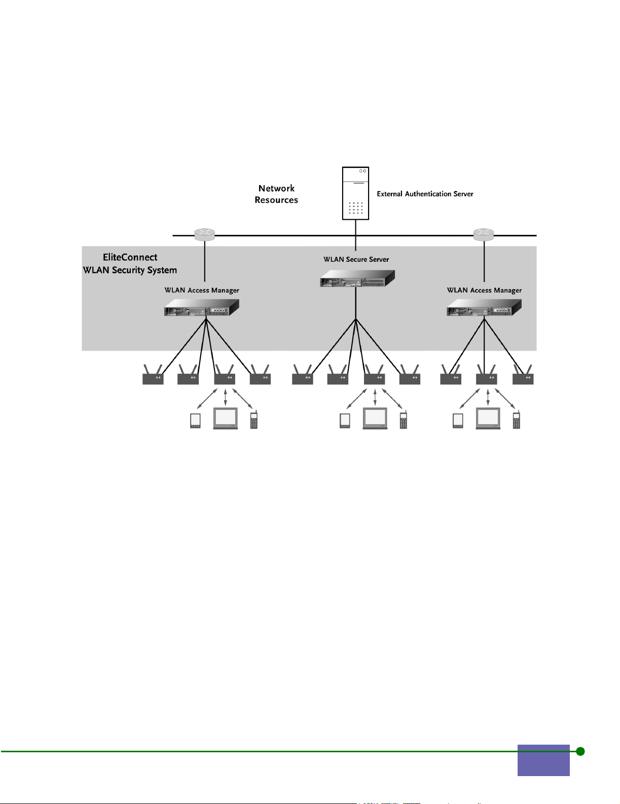
1.2 The EliteConnect WLAN Security System
Figure 1-1 shows the EliteConnect WLAN Security System.
Figure 1-1. The SMC EliteConnect WLAN Security System Solution
The EliteConnect WLAN Security System consists of three logical functions:
• WLAN Access Manager
• Control Server
• Rights Manager
There are two physical components of the EliteConnect WLAN Security System:
• The WLAN Secure Server consists of a Control Server, Rights Manager, and
WLAN Access Manager with four RJ-45 ports
• The WLAN Access Manager consists of the WLAN Access Manager function
with four RJ-45 ports
The next section explains the three logical functions.
SMC EliteConnect WLAN Security System User Manual 1-3
Page 22

1.2.1 WLAN Access Manager
The WLAN Access Manager is positioned between each access point and the
network. It inspects and filters each packet arriving from the wireless client
through the access point, deciding whether to allow or deny forwarding of the
packet. The WLAN Access Manager applies a set of rules to each packet. Allowed
packets can be redirected based on other rule sets.
Initially, the WLAN Access Manager knows of no connected devices. As a user
sends a packet through a wireless access point, it forwards the packet to the
network through the WLAN Access Manager. The WLAN Access Manager uses
the received packet to determine the hardware MAC address of the client device,
and requests an initial set of rights from the Rights Manager through the WLAN
Secure Server.
The Rights Manager supplies a set of logon rights that allow DHCP, DNS, and
HTTP requests, additionally redirecting HTTP requests to the Rights Manager. The
Rights Manager uses the first HTTP request to require user authentication by
means of an SSL-protected HTTP connection. After verifying a user’s identity
through the HTTPS connection, the Rights Manager sends a new rights package
through the WLAN Secure Server, to the WLAN Access Manager. This rights
package is based on the user’s identity, location, and the time and date.
In addition to filtering and redirecting packets, the WLAN Access Manager
coordinates with other Access Managers through the WLAN Secure Server to
maintain connections as a client device roams from one access point to another.
The Access Manager is also responsible for maintaining Airwave Security
encryption using PPTP, L2TP, or IPSec protocols.
Scalability is ensured by concentrating all packet-level inspection and rewriting
functions and encryption at the WLAN Access Manager. An individual Control
Server can easily supervise several WLAN Access Managers.
1.2.2 Control Server
Each WLAN Secure Server administrative domain requires only one Control
Server, which is embedded in the WLAN Secure Server. The Control Server in the
WLAN Secure Server performs two functions:
•
Coordinates between the WLAN Access Managers and the Rights Manager
• Coordinates WLAN Access Manager-to-WLAN Access Manager communications, such
as a roaming handoff.
To ensure scalability, all per-packet operations are confined to the WLAN Access
Managers. The WLAN Secure Server merely coordinates the client metainformation among the WLAN Access Managers.
All policy and user database entries are kept in the Rights Manager, which is part
of the WLAN Secure Server.
1-4 Introduction
Page 23

Command and control communication between the WLAN Access Manager and
the WLAN Secure Server is through an encrypted connection. Command and
control communication between WLAN Access Managers is also through an
encrypted connection. User packets that must be tunneled between WLAN Access
Managers to ensure transparent Layer 3 roaming are not encrypted.
1.2.3 Rights Manager
The Rights Manager, which is part of the WLAN Secure Server, enables the
network administrator to edit rights for users, groups, locations, and times. It
supplies the WLAN Access Managers with appropriate rights based on who, when,
and where. The Rights Manager also authenticates users.
Users and Authentication
Active Authentication
As described earlier in WLAN Access Manager, the initial set of rights sent by the
Rights Manager to the WLAN Access Manager limits the packets allowed into the
network. Additionally, any HTTP requests from the end-user are redirected to the
Rights Manager. The Rights Manager sets up an HTTPS connection with the user,
and presents a logon screen.
The user types their username and password, or requests guest rights. Users are
authenticated, while guests are given a set of pre-defined rights that limit network
access to the external Internet.
The Rights Manager supports four methods of authentication:
• A built-in database of user-password pairs
• An interface to an external LDAP authentication service
• An interface to an external RADIUS service
• An interface to a Kerberos service
After performing the appropriate authentication, the Rights Manager determines
the correct set of rights for that particular user based on group membership,
geographic location of the client, day, and time of day. The Rights Manager also
offers an advanced authentication option in which multiple authentication
methods can be used.
SMC EliteConnect WLAN Security System User Manual 1-5
Page 24

Passive Authentication
Alternatively, you can choose one of the following passive methods for user-level
authentication. The following all require user-level authentication and the
EliteConnect WLAN Security System can use these authentication services for its
own user authentication:
• NT/2000 domain login
• 802.1x authentication
• PPTP MS-CHAP, or MS-CHAP v2 authentication
• L2TP MS-CHAP or MS-CHAP v2 authentication
1.2.4 Rights
At any given time, for each client attached to a WLAN Access Manager, a certain
set of rights is in effect. These rights are based on the powerful packet-matching
language of the tcpdump utility program. A rights package contains the following
main components: Network Address Translation (NAT) setting, Mode Setting,
Packet Filters, and Session Redirectors. Each set of rights has a valid time.
Network Address Translation
A WLAN Access Manager provides Network Address Translation (NAT) services
for users who request DHCP IP address when they initiate connection to the
Access Manager.
When a client sends a packet through the WLAN Access Manager, the WLAN
Access Manager rewrites the IP address field and the port number field to a value
that is unique and that will identify any return packet.
Depending on the application, you can choose to use the NAT service or you can
choose to assign your own IP address. Following are some points in favor of and
against using NAT:
• NAT makes roaming much more efficient. The WLAN Security System can move
the entire connection state from one WLAN Access Manager to the roamed-to
WLAN Access Manager, and only tunnel open sessions back through the
original WLAN Access Manager. MobileIP as a solution to roaming suffers
because every connection has to be tunneled back through the original
connection point.
• NAT provides some amount of protection to a client since no device other than
the WLAN Access Manager can talk directly to the client. This provides
rudimentary firewall protection.
• Certain applications require a host or server system to know the actual IP
address of a client. Some examples include multi-player games, file transfer in
Instant Messenger applications, and other peer-to-peer applications.
1-6 Introduction
Page 25

NAT is enabled by default. You can choose to disable NAT based on individual
user’s needs. See Configuring the Rights Manager for more information about
configuring NAT.
Packet Filters
Each set of client rights has an associated set of packet filters that determine what
traffic the client is allowed to generate. Any packets generated by the client that
do not match one or more of the filters are quietly rejected. You can base filters for
packets on protocol, IP address, port, or other considerations. You can specify
packet filters to be as granular as you want, even to the point of specifying
individual bit patterns in the client’s packet.
Session Redirectors
Client TCP and UDP sessions can be redirected from their original destination IP
address or port. This is useful, for example, to force HTTP clients to login, or to
ensure that certain requests for network services, such as DNS, are directed to the
appropriate servers.
Some important notes about configuring rights:
• Filters and redirectors match packets using the powerful pattern matching
language introduced by the tcpdump utility program.
• If NAT is not enabled for a set of rights, then these rights should also include a
filter allowing clients to renew their DHCP leases.
• Often a session redirector will match client DNS requests and redirect them to a
known DNS server allowing for client misconfiguration of DNS.
Valid Times
A set of rights is valid for some time periods as specified by the system
administrator when configuring the rights. When the rights valid time expires, the
WLAN Access Manager queries the Rights Manager for a new set of rights, but
does not require re-authentication.
1.2.5 Timers
There are two important timers maintained by the WLAN Security System:
• Expire
• Linger
The Expire timer specifies how long before a user is required to re-authenticate.
The Linger time specifies how long a user has to roam once he disappears from
one WLAN Access Manager and before he reappears at another WLAN Access
Manager. A WLAN Access Manager periodically probes for a client after that client
is idle for a while. If the client does not respond to the probe (an ARP request) after
a period of idleness, the WLAN Access Manager removes the client’s data from its
SMC EliteConnect WLAN Security System User Manual 1-7
Page 26

internal tables and informs the Rights Manager. The Rights Manager starts the
linger timer. If the linger timer expires, the user must re-authenticate.
1-8 Introduction
Page 27

CONFIGURING THE WLAN SECURITY SYSTEM
This chapter describes how to configure the WLAN Secure Server and WLAN
Access Manager so that they work with your enterprise network after you have
installed it, as described in the EliteConnect WLAN Security System Installation
Guide. It includes the following sections:
2.1 Administrative Login . . . . . . . . . . . . . . . . . . . . . . . . . . . . . . . 2-2
2.2 Changing Your Network Configuration . . . . . . . . . . . . . . . 2-4
2.3 Advanced Network Settings . . . . . . . . . . . . . . . . . . . . . . . . . 2-6
2.4 Setting the Shared Secret . . . . . . . . . . . . . . . . . . . . . . . . . . . 2-10
2.5 Configuring SNMP . . . . . . . . . . . . . . . . . . . . . . . . . . . . . . . . 2-11
2.6 Specifying Location Description . . . . . . . . . . . . . . . . . . . . 2-13
2.7 Specifying Session Logging . . . . . . . . . . . . . . . . . . . . . . . . 2-14
2.8 Configuring the Time and Date . . . . . . . . . . . . . . . . . . . . . 2-15
2.9 Viewing Online Documentation and Help . . . . . . . . . . . . 2-16
2
Note: You can also use the EliteConnect WLAN Security System command-line interface for
configuration, which is described in
Command Line Interface.
March 18, 2002 3:12 pm 2-1
Page 28
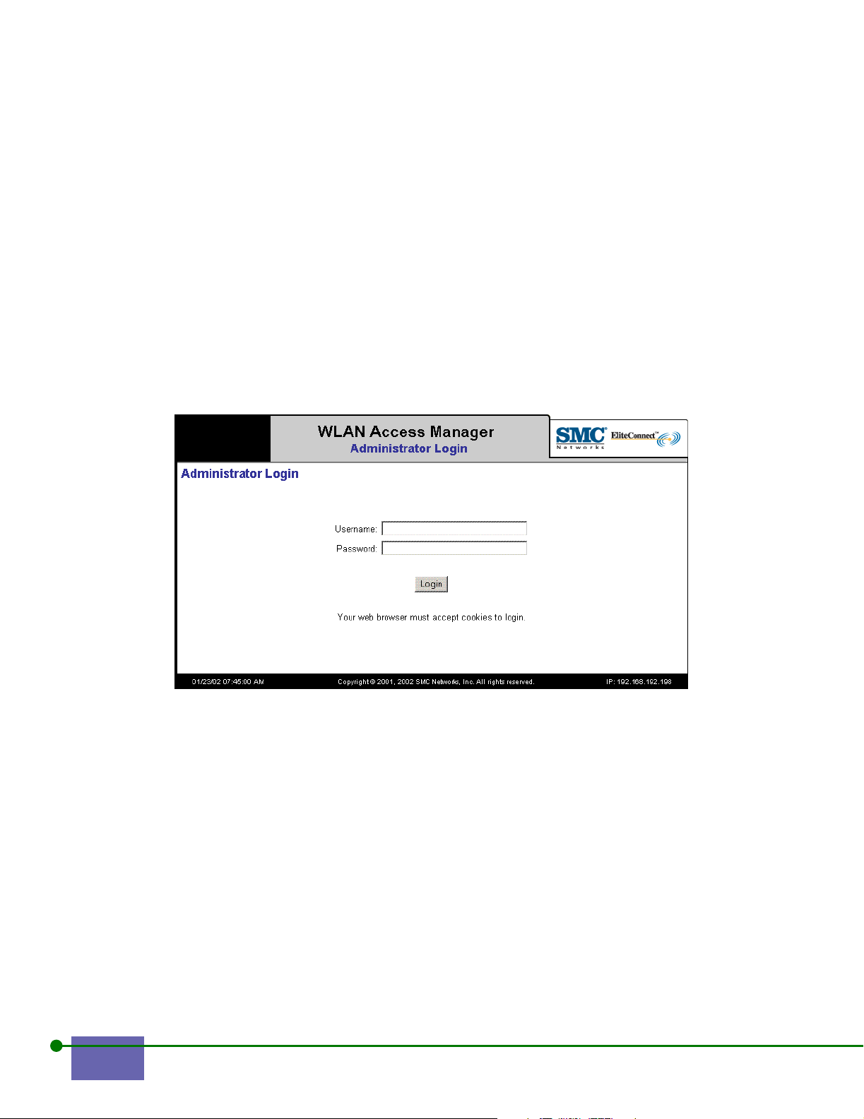
2.1 Administrative Login
To log in:
Step 1. Set your browser to the IP address or hostname of the WLAN Secure
Server or WLAN Access Manager
Step 2. Press Enter.
The Administrator Login Screen appears, as shown in Figure 2-1
Any system connected through a WLAN Access Manager’s or WLAN Secure
Server’s ports can access the web interface through the specially recognized URL:
http://42.0.0.1.
Note: Your browser must accept cookies to log in.
Figure 2-1. Administrator’s Login
Note: The text is adjusted appropriately depending on whether the component you are
connected to is a WLAN Secure Server or a WLAN Access Manager.
Step 3.
Note: By default, the system ships with the user name admin and password admin.
Step 4.
Step 5. Click Login.
Enter your username.
Enter your password.
The Main Menu appears. Figure 2-2 shows the Main Menu for the WLAN Secure
Server. Figure 2-3 shows the Main Menu for the WLAN Access Manager.
2-2 Configuring the WLAN Security System
Page 29
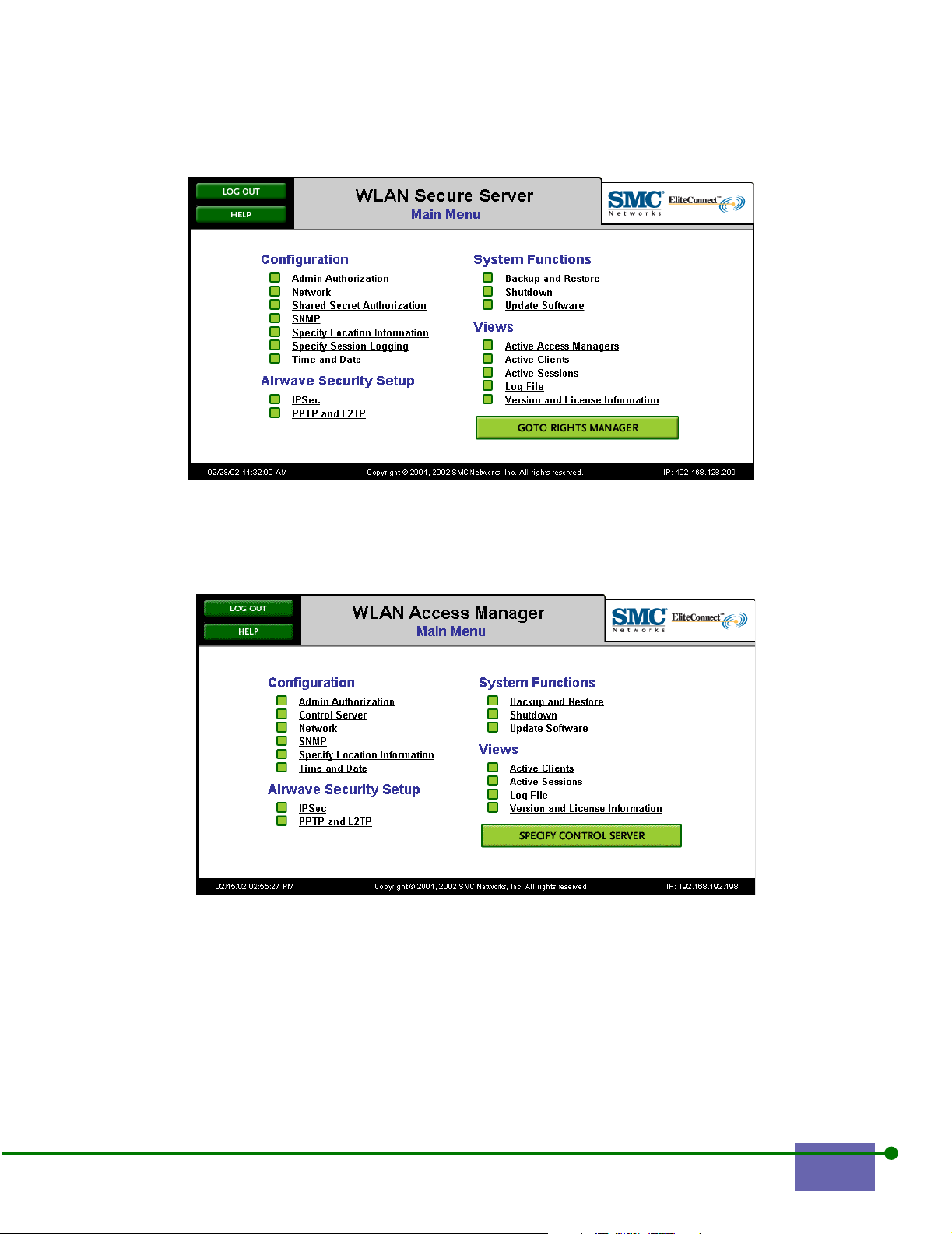
Figure 2-2. Main Menu for the WLAN Secure Server
Figure 2-3. Main Menu for the WLAN Access Manager
EliteConnect WLAN Security System User Manual 2-3
Page 30
This chapter explains the Configuration functions of the Main Menu; other topics
are discussed in other chapters, as shown in Table 2-1.
Table 2-1 Topics in Other Chapters
Top ic Chapter
Airwave Security 3
System Functions 4
Viewing the System 5
2.2 Changing Your Network Configuration
The WLAN Security System Installation Manual explains initial network installation.
Refer to this section if you need to change your network configuration.
To change your network configuration:
Step 1. Click Network from the Main Menu.
Figure 2-4 shows the Network Configuration screen for the WLAN Secure Server.
Figure 2-5 shows the Network Configuration screen for the WLAN Access
Manager.
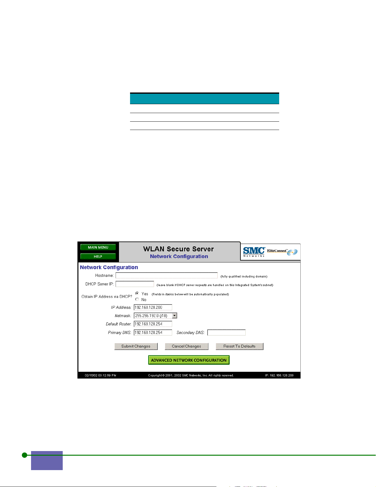
Figure 2-4. Network Configuration for the WLAN Secure Server
2-4 Configuring the WLAN Security System
Page 31
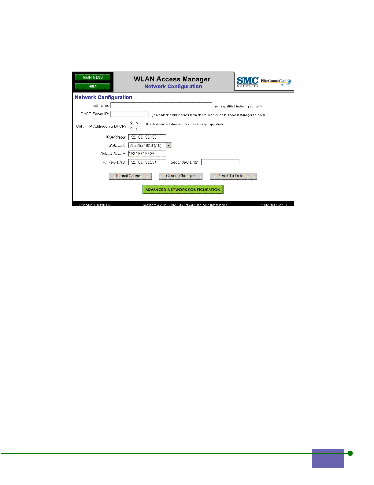
Figure 2-5. Network Configuration for the WLAN Access Manager
Step 2. Type the hostname as a fully qualified domain name.
Note: SMC recommends creating a hostname. Use a hostname to prevent your users from
getting SSL warning about an unknown SSL certificate when they first see the Logon
screen. If you enter a hostname, the DNS at your site must resolve the hostname to the
IP address you select.
Step 3.
Type the DCHP Server IP address.
Leave this field blank if DHCP server requests are handled on this WLAN
Access Manager’s or WLAN Secure Server’s subnet.
Note: There are two ways for a WLAN Access Manager to pass DHCP requests from a client
to a DHCP server located somewhere on the network. This applies only to clients that
are not using Network Address Translation (NAT), since a network-address translated
client will have its DHCP request satisfied by the WLAN Access Manager itself.
• The first way to handle DHCP requests is by bridging. This means that the WLAN
Access Manager or WLAN Secure Server simply copies the DHCP request from the
client to the WLAN Access Manager's or WLAN Secure Server’s subnet. Assuming
there is a DHCP server on the subnet or a DHCP-forwarding router, the DHCP server
replies with the IP address and other information the DHCP server provides, and the
WLAN Access Manager or WLAN Secure Server sends the reply on to the client. As
far as the client is concerned, it is connected directly to the DHCP server.
• If there is no DHCP server on the WLAN Access Manager's or WLAN Secure Server’s
subnet nor any DHCP-forwarding router, then the WLAN Access Manager or WLAN
EliteConnect WLAN Security System User Manual 2-5
Page 32

Secure Server needs to know how to locate the DHCP server. In this case, called
DHCP relay, the WLAN Access Manager relays the client DHCP request to the DHCP
server at the administrator-specified IP address. When the WLAN Access Manager or
WLAN Secure Server receives the reply, it relays it to the client.
Step 4. Click Yes to Obtain IP Address via DHCP.
If you click Yes, the unit will request its IP address, subnet mask, gateway,
and DNS IP address from a DHCP server.
Step 5. Choose the Netmask address from the drop-down box.
Step 6. Type the Default Router IP address.
Step 7. Type the Primary DNS server IP address, and if applicable, the
Secondary DNS server IP address.
Step 8. Click Submit Changes to save your settings.
Step 9. Click the Advanced Network Configuration to configure advanced
network settings, as described in Advanced Network Settings.
2.3 Advanced Network Settings
To configure advanced network settings:
Step 1. Click Advanced Network Configuration on the Network Configuration
screen.
The Advanced Network screen appears, as shown in Figure 2-4.
Note: The screens for the WLAN Access Manager and WLAN Secure Server are the same.
2-6 Configuring the WLAN Security System
Page 33

Figure 2-6. Advanced Network Configuration for the WLAN Secure Server
Step 2. Enable Ethernet Bridging, if appropriate for this WLAN Secure Server or
WLAN Access Manager. A WLAN Security System is a Layer 3 device
that provides filtering and redirection of IP packets at Layer 3. With
bridging, you can specify certain Layer 2 packets to be copied across a
WLAN Secure Server or WLAN Access Manager.
Step 3. For Bridged traffic:
a. Click Cisco Discovery Protocol to enable CDP packets through this
WLAN Secure Server or WLAN Access Manager.
This Layer 2 protocol is used by Cisco network hardware and
software to manage a network of Cisco devices.
b. Click Wireless Network Access Protocol to enable WNMP packets
through this WLAN Secure Server or WLAN Access Manager.
This Layer 2 protocol is used by Symbol Technologies, Inc. network
hardware to manage a network of Symbol devices.
c. Click Enable IP Multicast.
This enables multicast packets to be copied from the Network Uplink
subnet to all clients connected to ports on this WLAN Secure Server
or WLAN Access Manager.
EliteConnect WLAN Security System User Manual 2-7
Page 34

d. Click Other.
You can enter arbitrary tcpdump syntax in this box to specify what
Layer 2 traffic to allow through this WLAN Secure Server or WLAN
Access Manager. Any tcpdump-enabled packets are in addition to
those enabled by checking CDP, WNMP, or Multicast options, above.
See Appendix A for a description of tcpdump syntax.
Examples:
CDP enable tcpdump syntax ether [12:2]<= 1514 and ether dst 01:00:0c:cc:cc:cc and ether[14:4]
= 0xaaaa0300 and ether[18:4] = 0x000c2000
WNMP enable tcpdump
syntax
Multicast ip[16:4]&0xf000000=0xe0000000
Step 4. Type the number of seconds for client probes: the amount of idle time
ether [12:2] = 0x8781 and ether[0:4] = 0x01a0f8f0
before the WLAN Security System checks on the client.
When the client is idle, that is, when it is not sending any packets to the
network, this timer runs. When the client probes timer expires, the
WLAN Secure Server or WLAN Access Manager probes the client by
sending it an ARP request. The WLAN Secure Server continues sending
ARP requests at the specified interval as long as the client is idle.
Step 5. Type the number of seconds of idle time to disassociate clients after.
This counter determines how long a client must be idle before the WLAN
Access Manager disassociates that client. A disassociation is:
1) the WLAN Access Manager forgets the client and the client’s MAC
address, and wipes its rights from memory;
2) the WLAN Access Manager sends a message to the Rights Manager,
which tells the Rights Manager that the client is no longer connected. At
this point the Rights Manager starts the linger timer. The linger timer is
how long a client has to re-establish communication before it must reauthenticate See Configuring the Rights Manager for more information
on the linger timer.
Step 6. Click the checkboxes for those ports on which you want to Forward
broadcast IP packets to clients. You can click none, any, or all of the ports.
IMPORTANT:
Enabling this functionality permits broadcast IP packets to be transmitted to all clients on the selected
ports, even unauthenticated clients. In some circumstances, broadcast IP packets contain sensitive information that network administrators prefer to keep from unauthenticated users.
Step 7. Configure the Port Settings.
Clients connected to WLAN Access Manager or WLAN Secure Server ports can
obtain an IP address in one of three ways:
• NAT mode: the WLAN Access Manager or WLAN Secure Server responds to a
DHCP request from a client with an address on the logical subnet 42.x.x.x. The
2-8 Configuring the WLAN Security System
Page 35

WLAN Access Manager or WLAN Secure Server will then rewrite source IP
address and source port number of client packets sent to the network (NAT and
PAT functions). Packets received by a WLAN Access Manager or WLAN Secure
Server from the network sent in reply to the NAT and PAT packets are relayed
to the appropriate client with the destination IP address and destination port
number rewritten as appropriate.
Note: Normally a client that uses an IP address that is not on the WLAN Access Manager or
WLAN Secure Server's subnet, or that uses the IP address of the WLAN Access
Manager or WLAN Secure Server itself, or that uses an IP address on the WLAN Access
Manager or WLAN Secure Server's subnet, but which does not have NAT-mode
disabled, will automatically be assigned NAT mode.
• Non-NAT, static IP mode: the client uses a pre-assigned IP address on the
WLAN Access Manager or WLAN Secure Server's subnet. Packets received by
the WLAN Access Manager or WLAN Secure Server with this static IP address
in the destination IP address field are forwarded to the appropriate client.
Packets from the client to the network do not have their source IP address or
source port number rewritten.
• Non-NAT, dynamic IP mode: the client sends a DHCP request for an IP address
which the WLAN Access Manager or WLAN Secure Server passes on to an
external DHCP server. This DHCP request will obtain an IP address on the
WLAN Access Manager or WLAN Secure Server's subnet. Packets received by
the WLAN Access Manager or WLAN Secure Server with the IP address
returned by the external DHCP server are forwarded to the appropriate client.
Packets from the client to the network do not have their source IP address or
source port number rewritten.
You can use the Port Settings facility to modify this behavior. If you fill in the IP
address and subnet mask for a WLAN Access Manager or WLAN Secure Server
port, under Port Settings then only for non-NAT mode clients:
• If a client makes a DHCP request, and you have configured an external DHCP
server IP address, then the WLAN Access Manager or WLAN Secure Server
will relay the DHCP request, but indicating the client originating the request
is on the subnet as specified in the Port Settings for that particular port. This
indicates to the external DHCP server that it should allocate an IP address on
that subnet.
• If a client has the real IP right and uses an IP address on the subnet as defined
by the Port Settings for that particular port, then the WLAN Access Manager
or WLAN Secure Server will not NAT that client's sessions.
In either case, the WLAN Access Manager or WLAN Secure Server will forward
packets from the network to a client IP address on a subnet defined in the Port
Settings to the appropriate client.
EliteConnect WLAN Security System User Manual 2-9
Page 36

Note: Network routers must be configured to route traffic destined for the subnet defined by
the Port Settings to the WLAN Access Manager or WLAN Secure Server.
Step 8.
Click Update.
2.4 Setting the Shared Secret
All WLAN Access Managers must prove to a system’s WLAN Secure Server that
they are trusted. A shared secret is used by the WLAN Access Manager to establish
this trust relationship. You must set this shared secret on the WLAN Secure Server
that controls one or more WLAN Access Managers.
2.4.1 Authorizing the Shared Secret on the WLAN Secure Server
To set the shared secret in a WLAN Secure Server:
Step 1. Click Shared Secret Authorization from the Main Menu.
The Shared Secret Authorization Configuration screen appears, as shown
in Figure 2-7.
Figure 2-7. Configure WLAN Access Manager Shared Secret
Step 2. Type the shared secret.
Step 3. Confirm the shared secret.
Step 4. Click Submit Changes.
2-10 Configuring the WLAN Security System
Page 37

2.4.2 Setting the Secure Server IP Address and Shared Secret
A WLAN Access Manager must know the address of its WLAN Secure Server. The
WLAN Access Manager must also know the shared secret to establish a trust
relationship with that WLAN Secure Server.
To set the Control Server, which is embedded in the Secure Server, and the IP
address from a WLAN Access Manager:
Step 1. Click Control Server from the Main Menu of the WLAN Access Manager.
The Specify the Control Server screen appears, as shown in Figure 2-8.
Figure 2-8. Specify the Control Server
Step 2. Type the Control Server IP address.
Step 3. Type the Secret Key.
Step 4. Confirm the Secret key.
Step 5. Click Submit Changes.
2.5 Configuring SNMP
The Simple Network Management Protocol (SNMP) is a standard for network
management. SNMP enables network administrators to manage their networks.
The SNMP subsystem enables the WLAN Access Manager and WLAN Secure
Server to be monitored via SNMP from a network management application such
as HP OpenView, Aprisma SPECTRUM, or SMC EliteView.
EliteConnect WLAN Security System User Manual 2-11
Page 38

Note: The WLAN Security System supports Management Information Base-2-compliant
objects. See the SNMP appendix for a list of Management Information Base (MIB)
objects.
To configure SNMP:
Step 1. Click SNMP from the Main Menu.
Note: This screen shows the values for the WLAN Secure Server. The screens for the WLAN
Access Manager are the same.
Figure 2-9. SNMP Configuration
Step 2. Determine whether you need SNMP to work with your overall network.
SNMP is disabled by default. Click Yes to enable SNMP.
Step 3. Type your Community Name, which is analogous to a password.
The default name is public; SMC recommends that you change it to increase
your security.
Step 4. Type the port number of your SNMP Port.
Port 161 is the default. If you change the port number, be careful that you do not
use a port that is used by another application.
Step 5. Type your Contact info: typically, this is the Network Administrator’s
name, email, or phone.
Step 6. Type your Trap IP address.
Certain events generate SNMP traps. The trap IP address is the recipient of this
2-12 Configuring the WLAN Security System
Page 39

information. Proprietary SNMP events include fan failure or restart, and out-ofrange temperatures. General SNMP trap events include SNMP authentication
failures, which are sent as trap information.
Note: Type the Tr ap I P add ress only if you have an SNMP trap receiver listening for this
information.
Step 7.
Type up to fo ur Manager IP addresses.
These are the addresses of SNMP consoles that are authorized to request
information from the WLAN Secure Server.
You can enter the following forms of Manager IP addresses: IP
addresses, such as 192.168.1.1; netmask addresses, such as
192.168.1.0/24; a hostname such as snmp.fiesta.com, or a wildcard
address, for example: 0.0.0.0/0.
Note: To query the SNMP agent from the SNMP console, you must include at least one
Manager IP address.
Step 8.
Click Submit Changes to save your settings.
2.6 Specifying Location Description
Specifying locations is helpful in a wireless system for system debugging and
management. This an optional screen. The WLAN Secure Server Location
information is readable by SNMP. This screen applies to the WLAN Access
Manager and WLAN Secure Server.
To specify location descriptions:
Step 1. Click Specify Location Information from the Main Menu.
The Location Information screen appears.
EliteConnect WLAN Security System User Manual 2-13
Page 40

Figure 2-10. Location Information
Step 2. Type the location of the WLAN Secure Server Location, for example,
Network Closet 2 on the 4th floor of the Physics Building.
Step 3. Type the location of Port 1, for example, Advanced Physics Lab.
Step 4. Type the location of Port 2, for example, Conference Room 12.
Step 5. Type the location of Port 3, for example, Centrifuge Room.
Step 6. Type the location of Port 4, for example, Applied Research Lab.
Step 7. Click Submit Changes to save your choices.
2.7 Specifying Session Logging
The WLAN Security System creates logs of session information, known as session
logs, for the WLAN Secure Servers and WLAN Access Managers. You can use these
logs for accounting and troubleshooting. These logs are sent to a remote server via
a
syslog protocol.
Note: You must configure session logging from a WLAN Secure Server; you cannot configure
session logging from a WLAN Access Manager.
To specify session logging:
Step 1. Click Specify Session Logging from the Main Menu.
The Specify Session Logging screen appears, as shown in Figure 2-11.
2-14 Configuring the WLAN Security System
Page 41
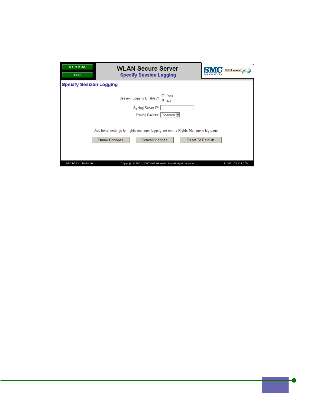
Figure 2-11. Specify Session Logging
Step 2. Click Yes to enable Session Login.
Step 3. Type a Syslog Server IP address.
Step 4. Choose your Syslog Facility from the drop-down list.
You can choose Daemon, User, or Local 0 through 7. Use Syslog settings
that interoperate with your enterprise Syslog server.
Step 5. Click Submit Changes.
2.8 Configuring the Time and Date
Accurate time and date reporting is necessary for logs and for troubleshooting.
Accurate and synchronized time and dates across multiple systems is especially
important. You use the Time and Date Configuration screen to set the System
timezones and date.
This screen applies to WLAN Access Managers and WLAN Secure Servers.
To configure the time and date:
Step 1. Click Time and Date from the Main Menu.
The Time and Date Configuration screen is shown in Figure 2-12.
Step 2. Click the arrow on the drop-down list and choose the time zone that is
appropriate for your location.
Note: Time zones are associated with major cities: for example, you would choose
America/New York for eastern standard time.
EliteConnect WLAN Security System User Manual 2-15
Page 42
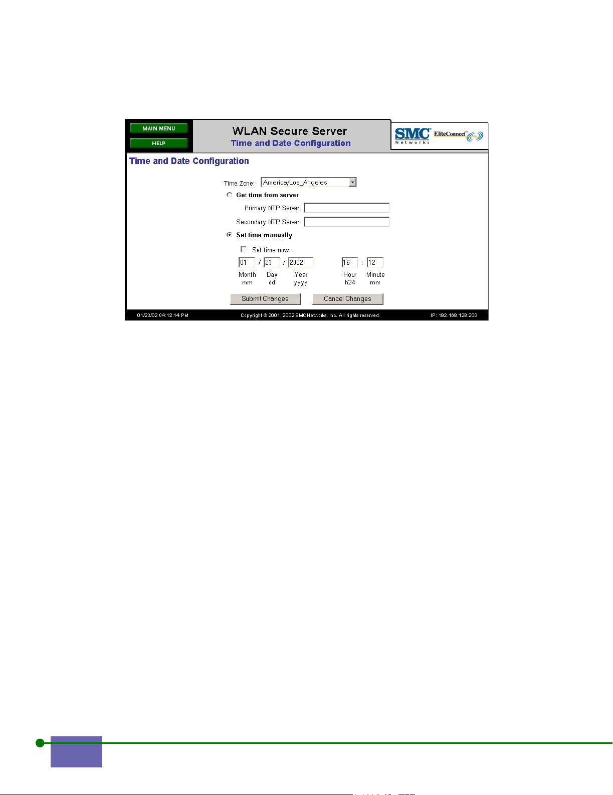
Figure 2-12. Configuring the Time and Date
You can either get the time from an NTP server or set it yourself.
Step 3. To use an NTP server, click Get time from server for a primary and an
optional secondary NTP server.
You can enter either a hostname or an IP address for the NTP servers.
Step 4. To configure the time manually:
a. Click Set time manually.
When you click Set time now, you disconnect from the NTP server.
b. Click Set time now to set the time with the fields below.
Type the date and time in mm-dd-yy format, the hour in 24-hour
format, and minutes in the fields shown in Figure 2-12.
Step 5. Click Submit Changes.
2.9 Viewing Online Documentation and Help
To view online documentation and help:
Step 1. Click Help from the Main menu.
The Help menu appears, as shown in Figure 2-13 for the WLAN Secure
Server.
2-16 Configuring the WLAN Security System
Page 43
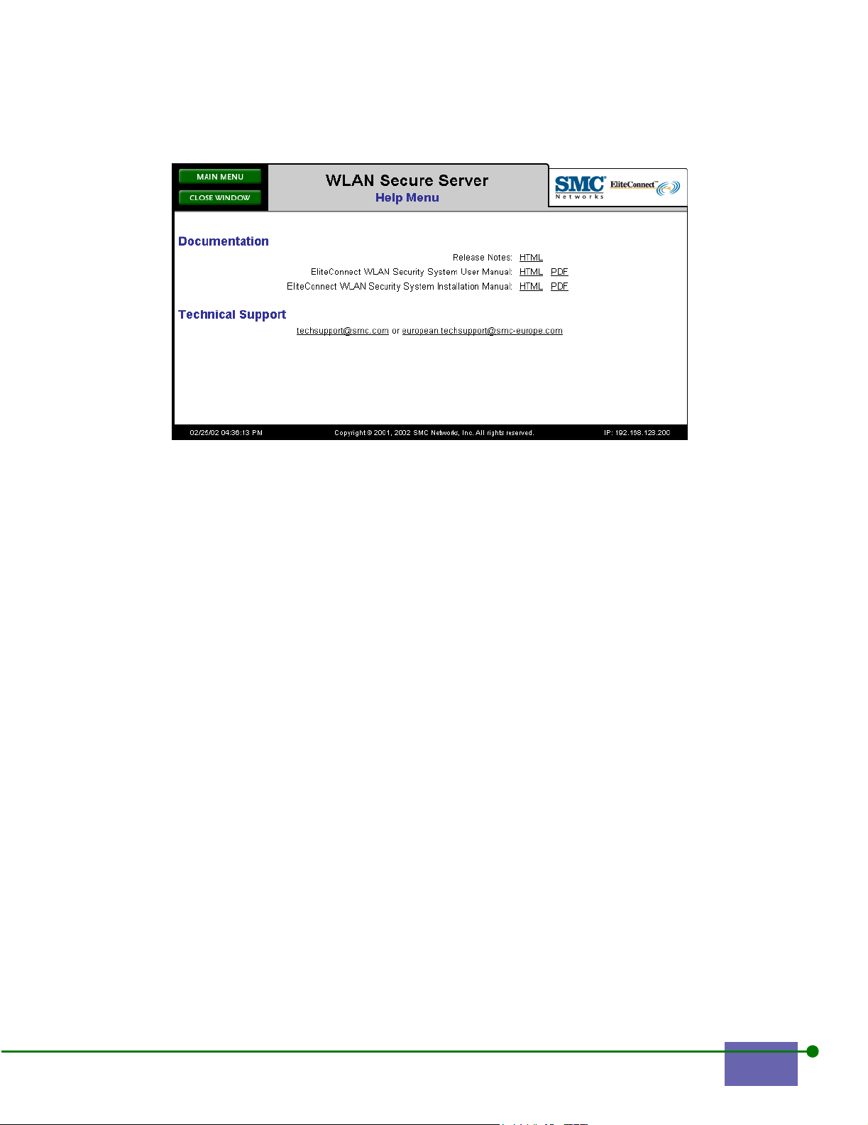
Figure 2-13. WLAN Secure Server Documentation and Release Notes
Step 2. Click EliteConnect WLAN Security System User Manual to see this
document in HTML or PDF format. The HTML pages of this document
contain blue hypertext links.
The online help is organized by the topic of the screen: for example, if you
click Help on the Time and Date screen, a screen appears with
information on setting the time and date.
Step 3. Review the information in the Release Notes so that you are aware of
recent changes. Information in release notes is the most up-to-date
information and supersedes the user and installation manuals.
Note: The WLAN Access Manager has no online help, user, or installation manual. If you click
Help when you are connected to a WLAN Secure Server, the server provides online
help for the screen.
EliteConnect WLAN Security System User Manual 2-17
Page 44

2-18 Configuring the WLAN Security System
Page 45

VPN SECURITY (AIRWAVE SECURITY)
This chapter explains how to secure the airwaves between the client and the
WLAN Access Manager or WLAN Secure Server. This VPN or Airwave security is
an integrated feature of the EliteConnect WLAN Security System that creates a
secure VPN tunnel to protect your information over the airwaves.
It includes the following topics:
3.1 Configuring VPN Security (Airwave Security) . . . . . . . . . 3-2
3.2 Configuring PPTP and L2TP . . . . . . . . . . . . . . . . . . . . . . . . 3-4
3.3 Configuring IPSec . . . . . . . . . . . . . . . . . . . . . . . . . . . . . . . . . 3-7
3
3-1
Page 46

3.1 Configuring VPN Security (Airwave Security)
VPN Security (Airwave Security) is a VPN security feature of the WLAN Security
System that allows you to provide strong encryption of data between a client and
the WLAN Access Manager. Airwave Security provides additional security for
data sent over the airwaves, supplanting the relatively insecure Wired Equivalent
Privacy (WEP) of a wireless network.
The WLAN Secure Server offers three choices for encrypting data between a client
and the WLAN Access Manager: PPTP, L2TP/IPSec, and pure IPSec.
3.1.1 Point-to-Point Tunneling Protocol (PPTP)
PPTP is a protocol defined by Microsoft for encrypting network data transfers. Its
advantages include its wide availability as it comes pre-installed on all versions of
the Windows operating system including Windows 9x, Windows ME, Windows
NT, Windows 2000, Windows XP, and Windows CE.
PPTP can use a variety of user-level authentication algorithms, including
Microsoft Challenge Handshake Authentication Protocol (MS-CHAP and MSCHAP version 2). The WLAN Security System can use the PPTP user
authentication for its own authentication. In this case, the WLAN Secure Server
login page is not necessary. For encryption, it uses either 40-bit or 128-bit MPPE
(Microsoft Point-to-Point Encryption), which employs the RC4 encryption
algorithm.
3.1.2 L2TP/IPSec
L2TP/IPSec is also a Microsoft protocol. It uses the standard IPSec (IP Security)
protocol to encrypt network communications and uses L2TP, an updated and more
secure version of PPTP, for IP address management and user-level authentication.
L2TP clients are pre-installed on Windows 2000 and Windows XP operating
systems.
L2TP can use the same user-level authentication algorithms as PPTP: MS-CHAP
and MS-CHAPv2. As with PPTP, the WLAN Security System can use the L2TP user
authentication as its own authentication. L2TP does not itself provide for any data
encryption; instead, it uses IPSec to encrypt data; see IPSec.
Both PPTP and L2TP were originally designed as a means for remote users,
typically the traveling business person, to access their home network while on the
road. As such, both protocols include IP address assignment features that are not
really necessary in a wireless environment. Both protocols also include facilities for
user-level authentication and for non-IP protocols.
3-2 SMC EliteConnect WLAN Security System User Guide
Page 47

3.1.3 IPSec
IPSec is an industry-standard method for encrypting networking communications
that was designed specifically to work with IP networking. IPSec clients are
available from a variety of vendors. Clients known to interoperate with the WLAN
Secure Server IPSec implementation include ones from SafeNet, Netscreen, PGP,
and Certicom/Movian.
The IPSec standard does not include a specification for user-level authentication.
It does provide for machine-to-machine authentication using either certificatebased or shared secret-based authentication. The WLAN Security System only
supports shared secret IPSec authentication.
IPSec operates in two phases and uses encryption and a secure hash function for
each phase. The first phase, Internet Key Exchange (IKE) sets up a session key used
in the second phase to do the actual encryption. The second phase, Encapsulating
Security Payload (ESP), does the actual data encryption. Both the IKE and ESP
phases can use Data Encryption Standard (DES), Triple DES, Blowfish, or CAST
encryption.
The secure hash used for data integrity in both the IKE and ESP phases can be
either Secure Hash Algorithm 1 (SHA-1) or Message Digest 5 (MD5).
IPSec uses the Diffie-Hellman Public-Key-Interchange (PKI) to generate the persession encryption key during the IKE phase. Supported versions of the DiffieHellman key exchange include Group 1, 2, and 5.
In general, the client and the SMC system negotiate the type of hash, encryption,
and key-exchange algorithms. Configuration of IPSec on the WLAN Security
System consists primarily of noting which algorithm the SMC system is prepared
to negotiate. It is up to the client system to propose algorithms, and the SMC server
either agrees or not.
3.1.4 General Considerations
Selection of a particular VPN protocol involves several factors:
• necessity
• performance
• security
• availability
Necessity
You must first determine whether you require VPN Security as it imposes a fairly
heavy administrative burden and it slows the throughput of data between a client
and a WLAN Access Manager.
VPN Security (Airwave Security) 3-3
Page 48

VPN tunneling encrypts user data that passes between a client and the network.
Only those networks subject to snooping by unauthorized individuals need
encryption. Even those networks might be adequately protected by WEP
encryption.
If your network is subject to unauthorized interception of data and if WEP is
inadequate to protect this data, you should consider using VPN Security.
Performance and Security
Encryption and decryption of data imposes a computational load on both a client
computer system and the WLAN Access Manager. Encrypting and decrypting data
could slow data throughput by a factor of five or more. Although a more secure
algorithm is generally thought to be slower, that is not necessarily the case. Table
3-1 shows the various possible encryption algorithms and their relative
performance.
Table 3-1 Algorithms and their Relative Performance
Encryption algorithm Strength Encryption speed
128-bit RC4
56-bit DES fair fair
168-bit DES excellent slow
Blowfish good good
CAST good good
good good
Availability
As previously mentioned, the availability of a client is an important part of the
selection of an algorithm to use for VPN Security. Table 3-2 shows availability of
PPTP, L2TP/IPSec, and pure IPSec clients known to interoperate with the WLAN
Secure Server VPN Security:
Table 3-2 Availability of Algorithms on Platforms
Algorithm Platform
PPTP
L2TP/IPSec
IPSec
Windows 95, Windows 98, Windows ME, Windows NT, Windows 2000,
Windows XP, Windows CE, and other vendors
Windows 2000, Windows XP
SafeNet, Netscreen, PGP, Certicom Movian
3.2 Configuring PPTP and L2TP
Configuration of PPTP and L2TP is done in two stages. The first stage configures
the WLAN Access Manager or WLAN Secure Server, and the second stage
configures the Rights Manager location, which is part of the WLAN Secure Server,
that allows (or requires) PPTP and L2TP.
3-4 SMC EliteConnect WLAN Security System User Guide
Page 49

The WLAN Access Manager configuration of PPTP and L2TP is relatively simple.
First, you either enable or disable PPTP and L2TP. Then, you configure IP address
assignment.
Since PPTP and L2TP were originally designed as remote access protocols, used by
traveling clients to access their home network, the PPTP and L2TP protocol assigns
an IP address to the client computer. But in a WLAN Secure Server environment,
a client usually obtains an IP address before enabling PPTP and L2TP encryption.
This results in two IP addresses: an initial one that describes the PPTP or L2TP
tunnel, and one that describes the actual IP address used by the client.
The WLAN Access Manager can be configured in one of two ways to assign this
inner-tunnel address: it can either assign an address from a range of addresses prespecified by the network administrator, or it can request an external DHCP server
to assign an address.
In addition to configuring the WLAN Access Manager, you must also configure the
location in the Rights Manager in order to use PPTP and L2TP. When you configure
a location to use PPTP or L2TP, you must decide how to do PPTP and L2TP user
authentication. For PPTP only, you must specify the strength of MPPE (RC4)
encryption to use.
Note: Configuring a location to use PPTP and L2TP encryption has a non-obvious effect on
how IP addresses are assigned at that location. Normally, an WLAN Access Manager
provides an IP address for clients with NAT mode enabled and for non-NAT clients,
passes any DHCP requests to an external DHCP server. When you configure a location
to use PPTP or L2TP encryption, you actually get two IP addresses: one is the IP address
of the tunnel that encapsulates all data packets; the other is the IP address of the client.
If a location is going to use PPTP encryption, this outer tunnel address must be assigned
by the WLAN Access Manager. The inner tunnel IP address can then be selected to be
assigned by the WLAN Access Manager or an external DHCP server. For more
information, see
Figure 3-1.
There are three ways to perform PPTP and L2TP user authentication at a location.
You can do the authentication through a RADIUS authentication server; you can
use the Rights Manager’s built-in username and password database, or you can
use a shared secret.
Caution: Using a shared secret is inherently insecure and should not be used if at all possible. It is
provided as a convenience for sites who cannot or choose not to use RADIUS or the
built-in server.
If you choose to use RADIUS or built-in authentication, the WLAN Secure Server
uses the PPTP/L2TP authentication both to authenticate the PPTP and L2TP
connection with a shared secret and to authenticate the user to the WLAN Security
System.
VPN Security (Airwave Security) 3-5
Page 50

If you choose the shared secret, all users at this location must enter the specified
shared secret when establishing their PPTP tunnel. The WLAN Security System
only uses the PPTP authentication to set up the PPTP connection. The user is
required to authenticate to the WLAN Security System through the usual webbased logon page.
Note: Since Microsoft links L2TP with L2TP IPSec, the WLAN Security System only supports
L2TP on IPsec. Enabling or requiring implicitly enables or allows use of IPSec.
3.2.1 Configuring PPTP or L2TP
To configure PPTP and L2TP:
Step 1. Click PPTP and L2TP Configuration from the Main menu.
The PPTP and L2TP Configuration appears, as shown in Figure 3-1.
Figure 3-1. PPTP and L2TP
Step 2. Click Yes for Enable PPTP, if appropriate.
Step 3. Click Yes for Enable L2TP, if appropriate.
Step 4. Click the appropriate method to assign an IP address to the IP client.
Since PPTP and L2TP are based on the remote access protocol PPP, it
expects the server to provide an IP address to a client when the
PPTP/L2TP connection is established. There are two ways to do this in
the WLAN Security System. You can either request the system to assign
an IP address from a pre-selected range of IP addresses or you can let an
external DHCP server assign as an IP address.
Step 5. If you clicked IP address range, type the appropriate IP address range for
your enterprise network.
3-6 SMC EliteConnect WLAN Security System User Guide
Page 51
Step 6. Click Submit Changes.
Note: To complete the PPTP or L2TP configuration, you need to configure PPTP settings as
shown above on the WLAN Access Manager, as well as the WLAN Secure Server’s
Rights Manager, and on the client application.
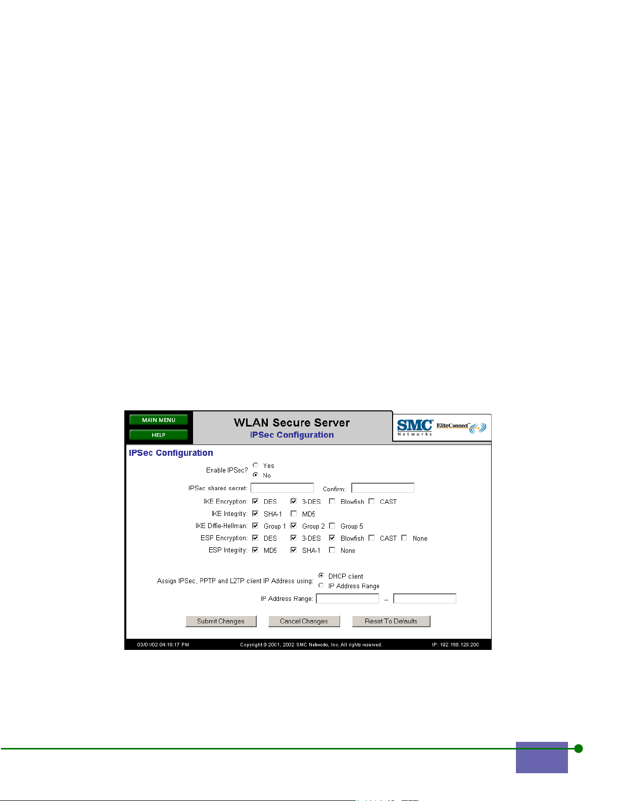
3.3 Configuring IPSec
Configuration of IPSec consists of three parts in the WLAN Access Manager:
enable or disable, specifying the shared secret, and checking allowed encryption
and secure hash algorithms. There is also an enable/require IPSec setting on a perlocation basis in the Rights Manager.
An IPSec client negotiates with the IPSec server to set the various options for
encryption and integrity assurance. The IPSec configuration screen allows the
network administrator to specify which IKE and ESP encryption and integrity
algorithms that the WLAN Secure Server and WLAN Access Manager will
negotiate with the client.
To configure security:
Step 1. Click IPSec Configuration from the Main Menu.
The IPsec Configuration screen appears, as shown in Figure 3-2.
Figure 3-2. IPSec Configuration
VPN Security (Airwave Security) 3-7
Page 52

Step 2. Click Yes button to enable IPSec.
Step 3. Enter your shared secret.
You are defining a shared secret to give to your IPSec users so that their
IPSec client software can prove they are authorized to use an IPSec
connection.
Note: The WLAN Secure Server does not support certificate-based authentication for an IPSec
connection. For Windows 2000 users and other clients that use certificate-based
authentication (by default) you must enable shared-secret authentication.
Step 4.
Step 5. Click MD5 and/or SHA for IKE integrity.
Step 6. Click the appropriate IKE Diffie-Hellman settings.
Step 7. Click the appropriate setting for ESP Encryption.
Step 8. Click the appropriate setting for ESP Integrity.
Click the appropriate type of Internet Key Encryption (IKE).
For those IPSec clients that define both outer- and inner-tunnel IP addresses,
specify how the inner-tunnel address is to be assigned.
Step 9. Click DHCP client to assign the inner-tunnel IP address via an external
DHCP server.
Step 10. Click IP Address Range and type the range of IP addresses to be assigned
by the WLAN Access Manager or WLAN Secure Server.
Step 11. Click Submit Changes to save your settings.
3-8 SMC EliteConnect WLAN Security System User Guide
Page 53

CONTROLLING THE SYSTEM FUNCTIONS
This chapter describes how to create, store, and restore a back up file, update
system software, and shut down the WLAN Secure Servers and WLAN Access
Managers. It also describes how to reset the SMC WLAN Secure Server to its
factory defaults.
It includes the following sections:
4.1 Creating and Storing a Backup Image . . . . . . . . . . . . . . . . 4-2
4.2 Restoring a Backed-Up Image . . . . . . . . . . . . . . . . . . . . . . . 4-5
4.3 Updating the System Software . . . . . . . . . . . . . . . . . . . . . . . 4-7
4.4 Rebooting or Shutting Down the System . . . . . . . . . . . . . . 4-9
4
4-1
Page 54

4.1 Creating and Storing a Backup Image
You should create backup files often of your WLAN Secure Server to ensure a
relatively painless recovery from any data loss. You must create a backup prior to
upgrading your software, as described in Updating the System Software, or if you
are restoring to factory defaults, as described in Rebooting or Shutting Down the
System.
There is almost always enough data on a WLAN Secure Server to make manual reentry of data unpleasant.
Note: Often multiple WLAN Access Managers contain nearly identical configuration, and the
amount of data kept in each WLAN Access Manager is small. You might consider
manually re-entering a WLAN Access Manager’s data, as necessary, rather than creating
a large backup file.
SMC recommends that you create data backups on a regular basis. If you make
significant changes to the Rights Manager, back up these changes.
4.1.1 Creating a Backup Image
To create a backup image of your software and settings:
Step 1. Click Backup and Restore from the Main Menu.
The Backup and Restore screen appears, as shown in Figure 4-1.
Figure 4-1. Backup and Restore
Note: The Save Backup button is dimmed because you have not yet created a backup file.
4-2 Controlling the System Functions
Page 55
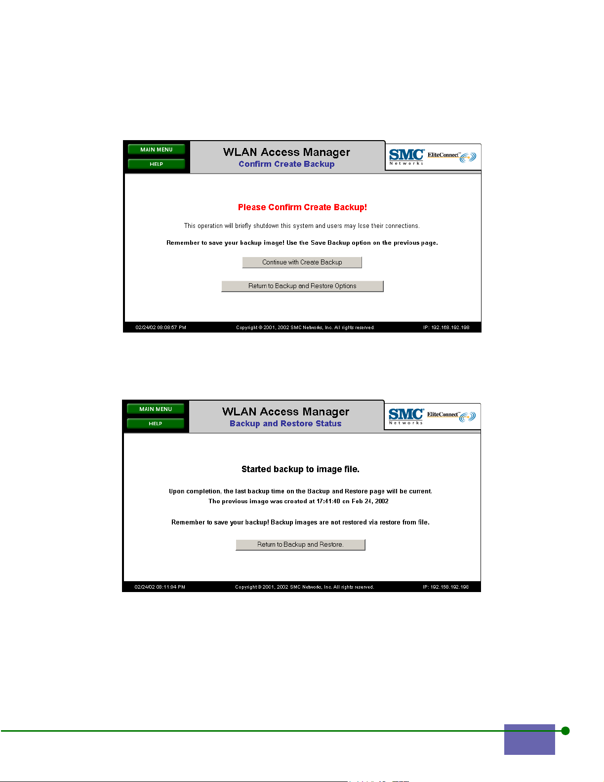
Step 2. Click Create Backup.
The Confirm Create Backup screen of appears, as shown in Figure 4-2.
Figure 4-2. Confirm Create Backup
Step 3. Click Continue with Create Backup.
The Starting to backup Image screen appears, as shown in Figure 4-3.
Figure 4-3. Starting to Backup Image
It is important that you save your back-up image to a local computer. If your
WLAN Secure Server configuration becomes inoperable, you can restore your
back-up image that is stored on another system.
SMC EliteConnect WLAN Security System User Guide 4-3
Page 56

Once you create your image file, you must save it to a local system. You cannot
restore a backed-up image from the WLAN Secure Server or WLAN Access
Manager.
4.1.2 Saving the Backup
To save the back up image to your local computer:
Step 1. Click Save Backup, as shown in Figure 4-4.
Figure 4-4. Saving the Restored Image
Step 2. Click OK.
Figure 4-5. Download Backup Screen
4-4 Controlling the System Functions
Page 57

The Save As screen appears, as shown in Figure 4-6. If you are using the Internet
Explorer browser, the following download pop-up screen appears. Other browsers
display similar screens.
Figure 4-6. Save As Screen on your local computer
The default backup image file name automatically appears next to File Name. You
can use this default or rename it. Choose the folder in which you want to store the
backup and click Save.
4.2 Restoring a Backed-Up Image
To restore a previously backed-up image:
Step 1. Click Backup and Restore from the Main menu.
The Backup and Restore screen appears, as shown in Figure 4-7.
SMC EliteConnect WLAN Security System User Guide 4-5
Page 58
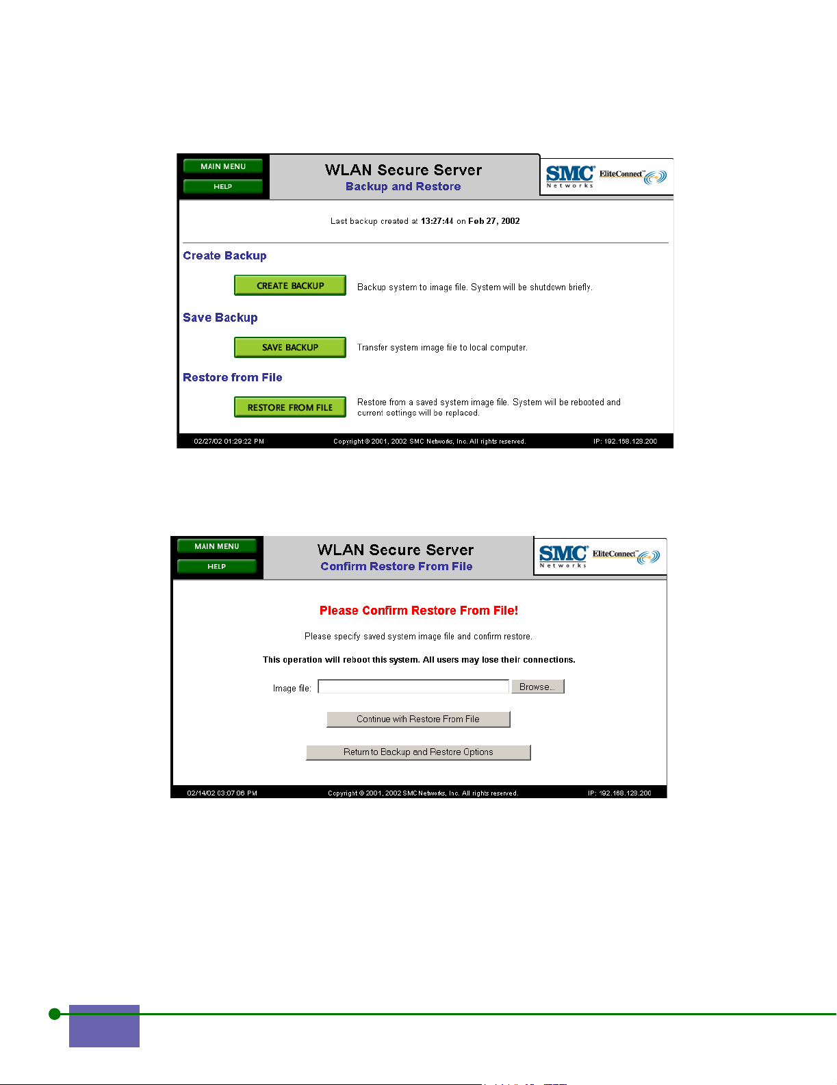
Figure 4-7. Backup and Restore Screen
Step 2. Click Restore From File.
The Confirm Restore from File screen appears, as shown in Figure 4-8.
Figure 4-8. Confirm Restore From File
Use the Browse feature, if necessary, to locate the backed-up image you want to
restore. Enter the backup image file name in the Image file text box.
Step 3. Click Continue to Restore from File.
When the file is completely restored, the Backup and Restore screen appears, as
shown in Figure 4-9
4-6 Controlling the System Functions
.
Page 59
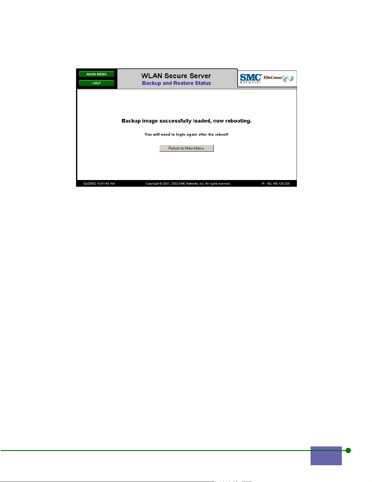
Figure 4-9. Backup Status Restore
Step 4. Click Return to Main Menu.
After the system reboots, you can start again using the restored image.
The system might take 90 seconds to reboot.
Note: If your system settings have become inconsistent, for example, a power failure occurred
while restoring from a backup, you can reset to factory defaults and reboot to restore the
initial system settings. However, you must reconfigure your system completely if you
restore from factory defaults. You can restore your setting from a back-up image.
4.3 Updating the System Software
Upgrading system software is a two-step process. First, download a new software
image. This new image becomes the Alternate Version. Then, reboot from the
Alternate Version, which automatically makes the older image the new alternate
version. This allows you to revert to the older images if the new image is
unsatisfactory.
IMPORTANT:
Before updating system software, it is prudent to create a backup of your current system software. See
Creating and Storing a Backup Image.
To update the system software:
Step 1. Click Update Software from the Main Menu.
The Update Software screen appears, as shown in Figure 4-10.
Step 2. Type the URL from which you want to download the software.
This field provides the latest version available. If you leave this blank, the
SMC EliteConnect WLAN Security System User Guide 4-7
Page 60
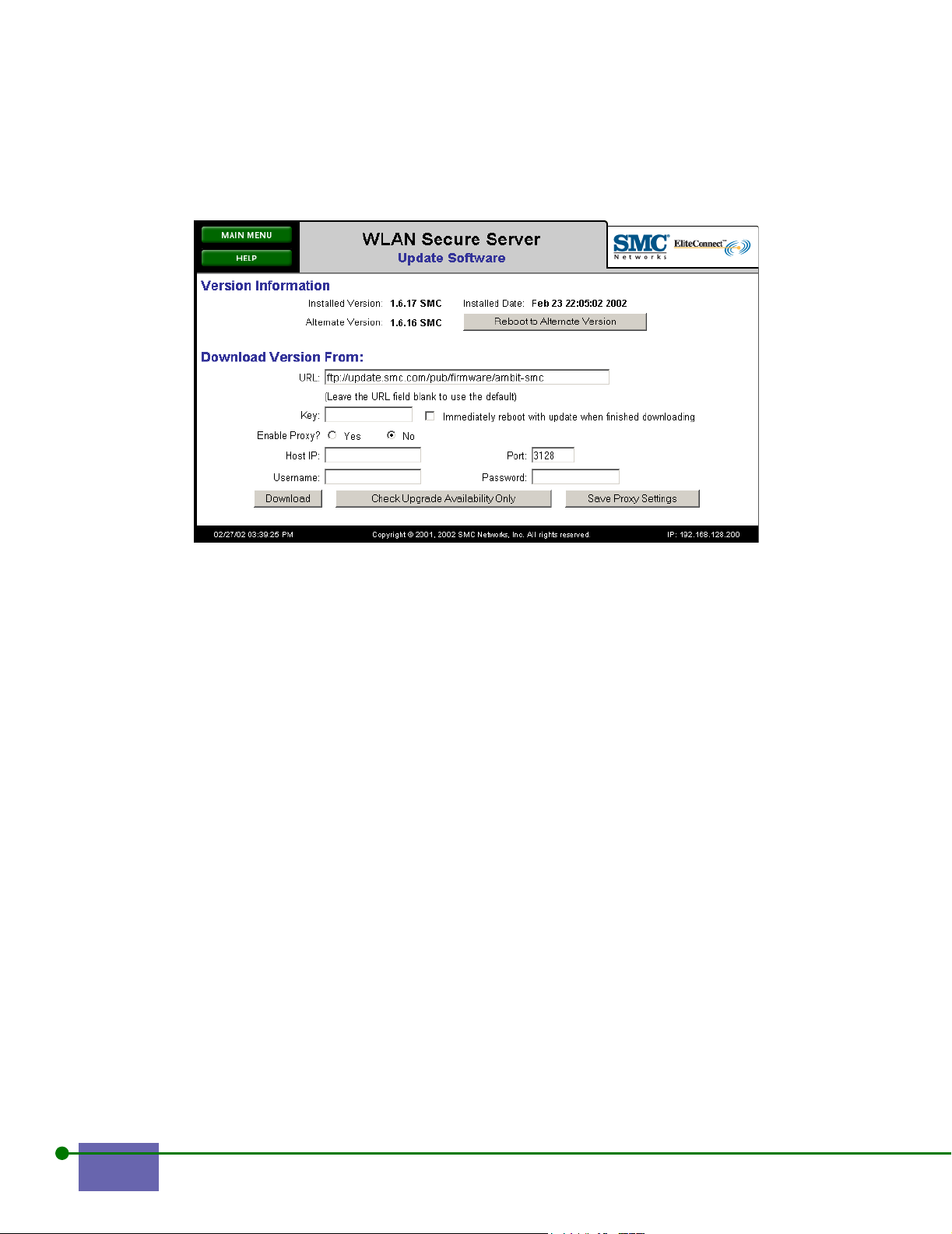
location defaults to an SMC FTP server site where upgrade images are
stored.
Figure 4-10. Entering the Update Software
Step 3. Type your Key.
The key is a password that enables you to use this version, which you get
from Technical Support.
Step 4. To reboot the system automatically and immediately after downloading,
check the box that says Immediately Reboot with update when finished
downloading.
Step 5. Enable Proxy, if appropriate.
An FTP proxy enables you to download the new image through an
enterprise firewall.
Step 6. If you enable the proxy, type the IP address of the FTP proxy server and
type the port number of the FTP proxy service (default is 3128), username,
and password.
Step 7. Click Save Proxy Settings.
It is helpful to save settings if you download new system software
periodically.
Step 8. Click Download.
The Update Software Process screen appears, as shown in Figure 4-11.
4-8 Controlling the System Functions
Page 61

Figure 4-11. Software Update Status
This is the initial status screen after you click Download. It has a Start refreshing
this page button; this screen does not refresh unless you click that button.
The screen refreshes approximately every 10 seconds, displaying updated status
information. After the download is complete, the status message indicates
unpacking the new image file. After unpacking is complete, the screen stops
refreshing, and a completion message appears:
New image successfully installed. Initiating reboot.
If you did not check the box that says Reboot with new version when finished
downloading, then the download proceeds, with the new software replacing the
alternate version software and without rebooting. The Update Software screen
displays both an installed version as well as an alternate version, as shown in
Figure 4-10. You are notified if the new image is successfully installed. You must
then reboot to the alternate version to complete the update of the software.
Note: Depending on the amount of data on your system, you might have to wait 90 seconds to
before you can log in again.
4.4 Rebooting or Shutting Down the System
To reboot, shut down, or reset your WLAN Secure Server to factory defaults
settings and reboot:
Step 1. Click System Shutdown from the Main Menu.
The System Shutdown appears, as shown in Figure 4-12.
SMC EliteConnect WLAN Security System User Guide 4-9
Page 62
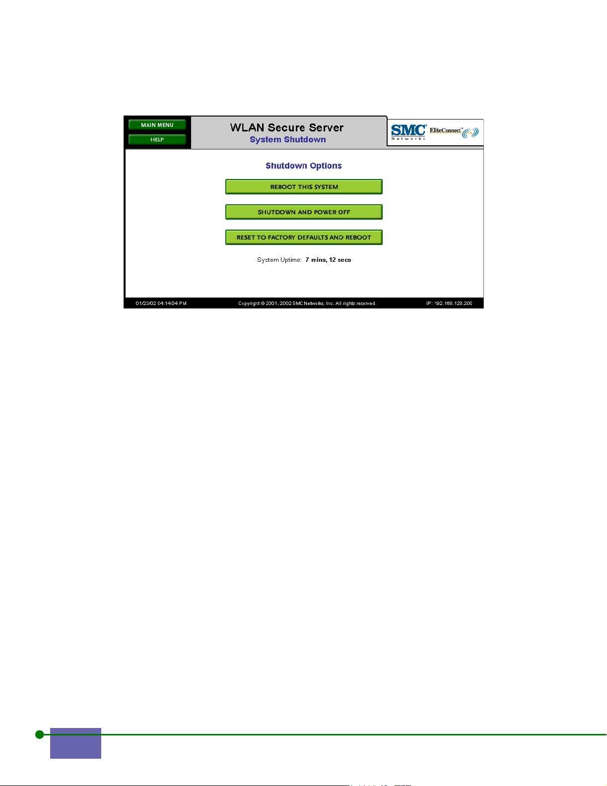
Figure 4-12. Shutdown Options
Step 2. Click Reboot this System to reboot.
The Confirm System Reboot screen appears. Click Continue with System
Reboot button to proceed with the reboot.
Step 3. Click Shutdown and Power Off to shut down the system.
The Confirm System Shutdown and Power Off screen appears. Click the
Continue with Shutdown and Power Off to proceed with the reboot.
Step 4. Click Reset to Factory Reset and Reboot to restore the original
configuration settings.
The Confirm Factory Reset and Reboot screen appears. Click the
Continue with Factory Reset and Reboot to proceed, as shown in Figure
4-13.
4-10 Controlling the System Functions
Page 63
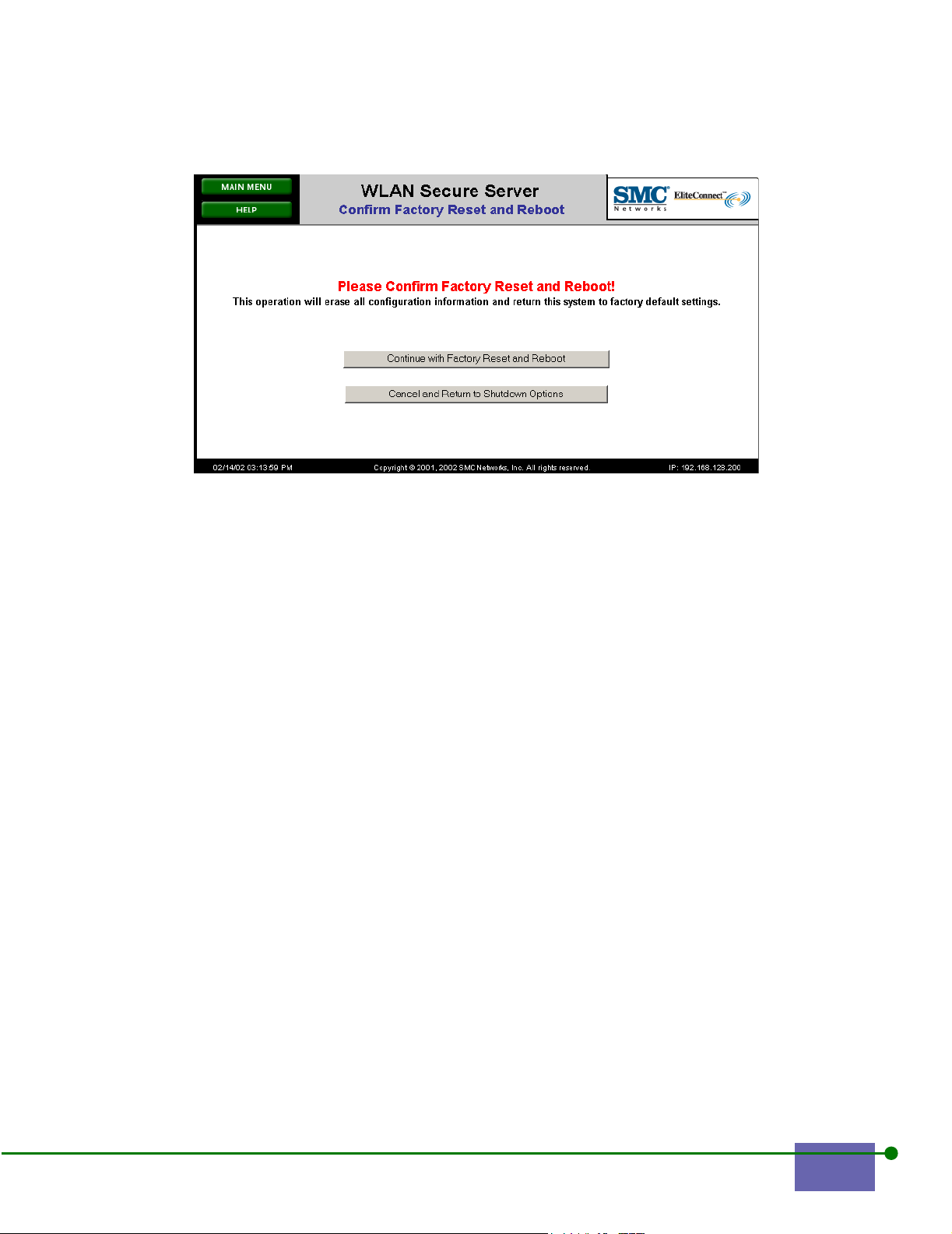
Figure 4-13. Confirm Reset to Factory Defaults
Caution: If you click this option, you must restore all settings from a backup image that was
created before the reset.
Step 5.
Click Main Menu if you do not want to reboot or shut down.
Caution: If you reboot a WLAN Access Manager, you will erase the logs and backup information.
SMC EliteConnect WLAN Security System User Guide 4-11
Page 64

4-12 Controlling the System Functions
Page 65

VIEWING SYSTEM STATUS
This chapter explains how to view the system status of the WLAN Secure Server
and WLAN Access Manager. It consists of the following sections:
5.2 Viewing WLAN Access Managers . . . . . . . . . . . . . . . . . . . . 5-3
5.3 Viewing the Active Client List . . . . . . . . . . . . . . . . . . . . . . . 5-4
5.4 Viewing Active Session Information . . . . . . . . . . . . . . . . . . 5-6
5.5 Viewing Log Files . . . . . . . . . . . . . . . . . . . . . . . . . . . . . . . . . . 5-7
5.6 Viewing Version and License Information . . . . . . . . . . . . . 5-9
Note: The text and the buttons are adjusted appropriately depending on whether the
component you are connected to is a WLAN Secure Server or a WLAN Access Manager.
Most of the images in this chapter are of a WLAN Secure Server, so the images might
contain options that are not available on a WLAN Access Manager.
5
5-1
Page 66
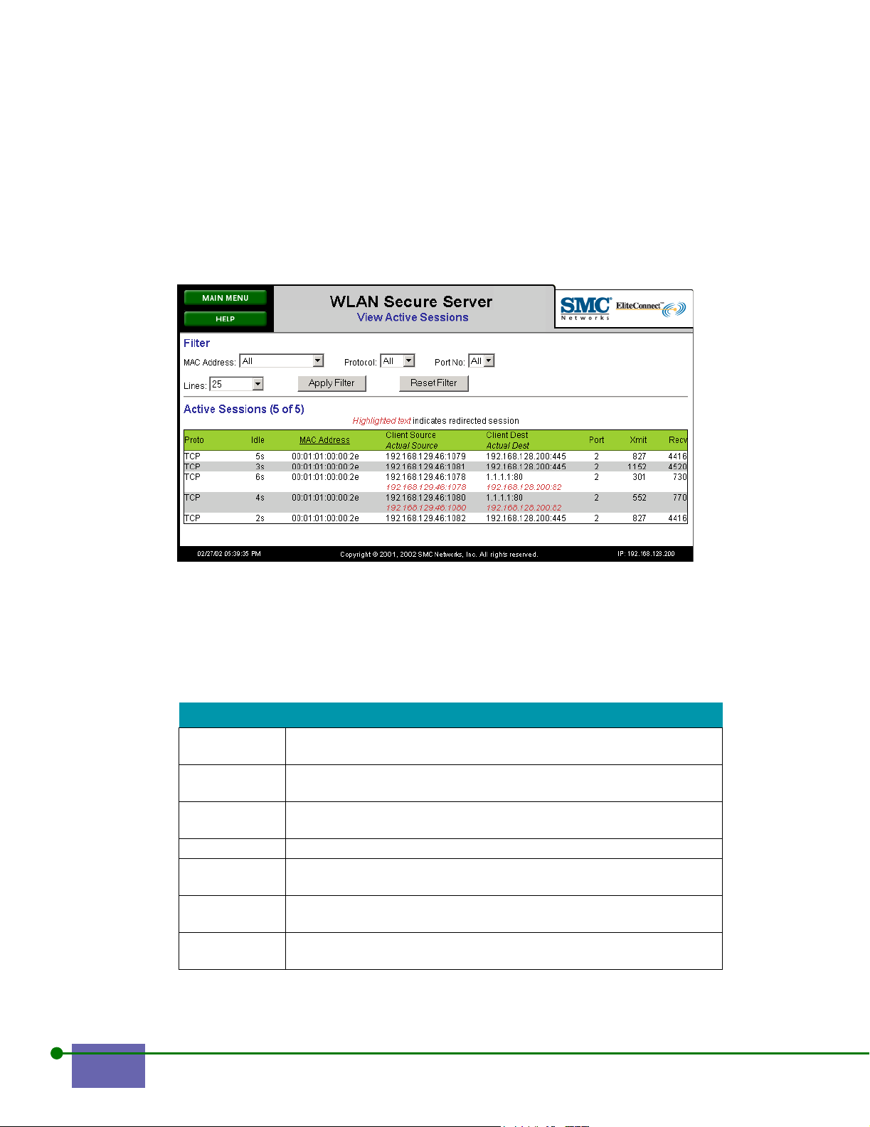
5.1 Viewing Status Information
This chapter explains how to view information about the WLAN Secure Server and
WLAN Access Manager. The screens that provide this information let you filter the
information. This enables you to easily find the WLAN Security System
information that you need.
Figure 5-1. View Active Sessions
To filter, click Apply Filter, as shown in Figure 5-1. To restore to the default filter,
click Reset Filter. Depending on the screen you view, you can filter on the
following entries:
Table 5-1 Filtering Information
Entry Details
Lines You can specify a number of entries to be displayed. The default is
25. You can choose 10, 25, 100, 1000, or unlimited.
Protocol Choose the protocol from the drop-down list; you can choose All, IP,
TCP, or UDP.
MAC Address Choose the MAC address from the drop-down list; you can choose
All or one of the MAC addresses shown.
Port number Choose All or one of the ports in the list.
Severity Choose the error type that you want to see; choose Notice, Critical,
Informational, Warning, or Error.
Within Choose the time period for which you want to view logs; you can
choose the past hour, day, week, or unlimited.
Search Type a string that you want to find. It can be any string on which you
want to search or filter.
5-2 Viewing System Status
Page 67

To sort column headings, click the column heading, such as MAC address or IP
address, as shown in Table 5-2
5.2 Viewing WLAN Access Managers
The WLAN Access Manager List shows all the currently connected WLAN Access
Managers to your WLAN Secure Server. Use this list to manage the WLAN Access
Managers. This screen is available only from the Main Menu of a WLAN Secure
Server.
To view the current list of WLAN Access Managers:
Step 1. Click View WLAN Access Manager List from the Main Menu.
The WLAN Access Manager list appears, as shown in Figure 5-2.
Figure 5-2. View WLAN Access Manager List
Step 2. To view more information about or to manage a particular WLAN Access
Manager, click on the IP address if it is underlined.
This takes you to the Main Menu of the WLAN Access Manager.
Note: A WLAN Secure Server and WLAN Access Manager share a single web interface, so the
IP address of a WLAN Access Manager portion of a WLAN Secure Server will not be
underlined.
Step 3.
To learn more about a specific client, click the appropriate entry in the
User column.
EliteConnect WLAN Security System User Manual 5-3
Page 68

5.3 Viewing the Active Client List
The Active Client list shows the status of all connected clients.
To view the Active Client List screen:
Step 1. Click View Active Clients from the Main Menu.
The View Active Client screen appears, as shown in Figure 5-3
Figure 5-3. View Active Clients
The screen presents user name, machine name, IP address, port number, sessions,
and the idle time for each active session.
Step 2. You can filter column headings or choose the number of lines to display,
as described in Table 5-1.
Step 3. To learn more about a specific client, click the entry with the user or MAC
address on it.
The client information screen appears, as shown Figure 5-4.
5-4 Viewing System Status
Page 69

Figure 5-4. Client Information
Table 5-2 Client Information
Information Description
Client The MAC address (hardware ID) of the client
User The name or the user, if known, otherwise the MAC address
Machine name The name of the machine, if known.
IP Address IP address for the client’s machine
Address Status Information about how your IP address was assigned
WLAN Access
Manager
The IP address of the WLAN Access Manager to which the user is
connected.
Port Number The port number of the WLAN Access Manager to which the user
is connected.
IP Security Displays the type of tunnelling protocol used by the client (none,
PPTP, L2TP, or IPSec); the type of authentication used by the
client, and the type of encryption used by the client
Log Info Click this link to see the WLAN Access Manager’s log file filtered
for entries that pertain to this client.
n Active
Click this link for more information about a client’s active sessions.
Session
Rights in XML Click this link to see the client’s rights in XML. See Configuring
the Rights Manager
for more information.
Rights Expire The amount of time in days, hours, and minutes before the rights
expire. This entry is the valid time for the rights, not the time left
before requiring re-authentication.
Step 4. Click the Logoff This Client to log off this client, if appropriate.
EliteConnect WLAN Security System User Manual 5-5
Page 70
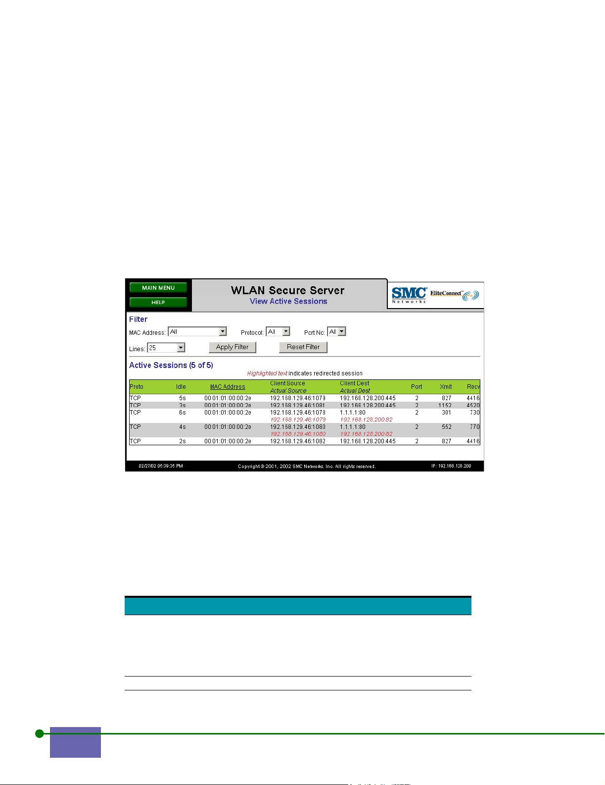
Step 5. Click the Go to Rights Manager, if appropriate.
Clicking this button takes you to the Home Rights Manager screen, as
shown in Figure 6-5.
5.4 Viewing Active Session Information
Viewing active sessions provides information on client’s open sessions. From this
screen, you learn more about a client’s network traffic.
To view active sessions:
Step 1. Click View Active Sessions.
The View Active Sessions screen appears, as shown in Figure 5-5.
Figure 5-5. Active Sessions
Step 2. You can filter by MAC address, protocol, port number, and by the number
of lines to be displayed.
Step 3. You can sort by MAC addresses.
The column headings provide the following information about sessions, as shown
in Table 5-3.
Table 5-3 Understanding the Active Session Information
Heading Description
Protocol The protocol for the client session. The following
protocols are translated from their numeric
strings: CMP, IGMP, TCP, UDP, ESP, AH, IP, and
PPTP. All other protocol are displayed as the
protocol number prefixed with a pound sign (#)
Idle The time since the last packet was received.
5-6 Viewing System Status
Page 71

Table 5-3 Understanding the Active Session Information
Heading Description
MAC address Lists the MAC addresses of all clients that are
currently connected or the specific client chosen
by the MAC address filter
Client Source
Actual Source
Client Destination
Actual Destination
Port The WLAN Access Manager or WLAN Secure
Xmit The number of bytes transmitted.
Recv The number of bytes received
When a client sends a packet, it puts its IP
address in the header of packet, which is the
client source. If the client address is Network
Address Translated by the WLAN Access
Manager, the WLAN Access Manager rewrites
the IP address so it appears as if the client comes
from the WLAN Access Manager, which is the
client’s actual source IP address and port number
The client puts a destination IP address in a
packet, which is the client destination. The WLAN
Security System can rewrite packet’s destination
IP address, which is the actual destination.
Server port number used by the session
5.5 Viewing Log Files
The WLAN Security System provides two types of logs for WLAN Secure Servers
and WLAN Access Managers:
• Informational logs that provide information about WLAN Security System
warnings
• Session logs that list each session
For information about Rights Manager logs, see Rights Manager Logs.
5.5.1 Informational Logs
Each WLAN Secure Server and WLAN Access Manager logs events to an internal
file. Viewing these logs provides important information on the activity of the
WLAN Secure Server and WLAN Access Manager.
To view log files:
Step 1. Click View Log Files from the Main Menu.
The Log File appears, as shown in Figure 5-6.
EliteConnect WLAN Security System User Manual 5-7
Page 72

Step 2. Click on any log file.
Step 3. The most recent entries are shown first by default. You can filter the
entries in reverse order time order by deselecting Show most recent first
and clicking Apply Filter.
Step 4. You can filter log files based on severity, time period, or search based on
any string you type; as described in Table 5-1.
Step 5. Click Apply Filter to view filtered results; click Reset Filter to reset to the
default view.
Step 6. Click Export Log as plain text to save the log as a plain text file on your
web browser’s system. You might want to archive or forward the log file.
Note: Click Clear Log File to empty the log file of older information.
5.5.2 Session logs
Session logs provide information about every completed session. These logs are
kept on a Syslog server.
A session log consists of a single line for each session. A typical session would be
represented as a string of parameters, delimited by spaces. These parameters are
defined in Table 5-4.
Figure 5-6. Viewing Log FIles
5-8 Viewing System Status
Page 73

Table 5-4 Session Log Parameters
Entry Name Definition
Start Start time of session in seconds since
1/1/2000 12:00am GMT
Duration Duration of session in seconds
MACaddr User’s MAC Address
Protocol Session Protocol
Client.Source Client Source IP and Port
Client.Dest Client Destination IP and Port
Actual.Source Actual Source IP and Port
Actual.Dest Actual Destination IP and Port
Bytes.Xmit Bytes Transmitted
Bytes.Rcvd Bytes Received
5.6 Viewing Version and License Information
You should know the current version of software run by your WLAN Security
System to upgrade your software or contact Technical Support. This page also tells
you the latest configuration change, IP address and Ethernet adapters.
To view version and license information, click Version and License Information
from the Main Menu.
EliteConnect WLAN Security System User Manual 5-9
Page 74

5-10 Viewing System Status
Page 75

CONFIGURING THE RIGHTS MANAGER
This chapter explains how to configure the Rights Manager for the WLAN Secure
Server. It includes the following sections:
6.1 Rights Manager Terminology . . . . . . . . . . . . . . . . . . . . . . . . 6-2
6.2 About the Rights Manager . . . . . . . . . . . . . . . . . . . . . . . . . . 6-3
6.3 Getting to the Rights Manager . . . . . . . . . . . . . . . . . . . . . . . 6-5
6.4 Changing Rights Associated with Locations . . . . . . . . . . . 6-6
6.5 Changing Group Properties . . . . . . . . . . . . . . . . . . . . . . . . 6-22
6.6 Adding, Modifying, or Deleting a User . . . . . . . . . . . . . . 6-34
6.7 Enforcing Authentication . . . . . . . . . . . . . . . . . . . . . . . . . . 6-40
6.8 Changing Rights-Allows in Groups . . . . . . . . . . . . . . . . . 6-50
6.9 Redirecting Packets . . . . . . . . . . . . . . . . . . . . . . . . . . . . . . . 6-54
6.10 Displaying Rights . . . . . . . . . . . . . . . . . . . . . . . . . . . . . . . . 6-63
6.11 Rights Manager Logs . . . . . . . . . . . . . . . . . . . . . . . . . . . . . 6-67
6.12 Importing and Exporting Rights . . . . . . . . . . . . . . . . . . . 6-68
6.13 Customizing the Logon Screen Appearance . . . . . . . . . 6-70
6
Note: The information in this chapter is further explained through real-life examples in the
Rights Tutorial appendix.
6-1
Page 76

6.1 Rights Manager Terminology
The Rights Manager uses common terms in a very specific manner. Before starting
to administer rights, make sure you understand these terms:
A Location is a group of wheres. A Where is a WLAN Access Manager or a WLAN
Access Manager port or a specific client. Some set of rights are associated with the
location. See Section 6.4.5, Changing WLAN Access Manager Rights for more
information. Locations have wheres and whens associated with them.
Everywhere else is the location that a client belongs to if it does not associate with
any other location. Until you create another location, this is the location to which
all clients are associated.
A When is set of valid times that apply to a location or a group. See Section 6.5,
Changing Group Properties.
Groups define rights for users who are members of the group. A user can be a
member of a group and is given rights as part of the group. An Allowed Group is
a group allowed at a specified location. Groups can be one of the following types:
• Guest: the rights given to someone who clicks the Guest button on the logon
page.
• Implicit users: the base group in which rights are allocated to all authenticated
users at the specified location.
• Normal: the only group that users can belong to. A user cannot belong to a
Logon, Guest or Implicit User group.
• Logon: the rights given to a client who has not yet logged on.
See Section 6.6, Adding, Modifying, or Deleting a User for more information about
users.
A Realm is an ordered list of authentication services. See the Rights Tutorial for
more information. There are both Rights Manager realms and Kerberos realms.
Kerberos realms refer to the domain specified by Kerberos.
Allows specify packets that are permitted to be forwarded by a WLAN Secure
Server or a WLAN Access Manager. Allows can include:
• Destination protocol
• Destination port
• Destination IP address
Redirects specify packets that are allowed to be forwarded, but require that these
packets be redirected to a new destination, also specified by the redirect. An
example is requesting a DNS server; packets could be redirected to the enterprise
DNS server rather than the one that was originally specified. Redirects can include:
• Original protocol
• Original port
• Original address
6-2 Configuring the Rights Manager
Page 77
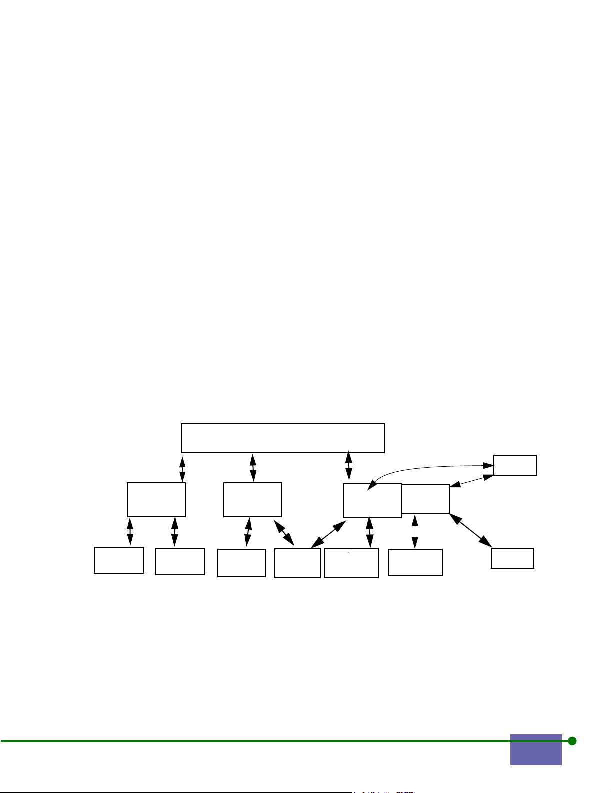
• Redirect port
• Redirect IP address
See Section 6.9, Redirecting Packets for more information.
Linger: a timer for how long the client is allowed to remain known by the Rights
Manager after being disassociated from the WLAN Access Manager. If the linger
setting is not exceeded, then the next time clients associate, they will receive the
rights they had before they disassociated
Expire: a timer that determines how long rights are valid after they are allocated
to a client.
6.2 About the Rights Manager
The Rights Manager is the portion of the WLAN Secure Server that allocates rights
to devices and users in the EliteConnect WLAN Security System. The Rights
Manager enables you to determine site policy based on location, user groups,
times, and other choices.
This chapter and the Rights Tutorial Appendix describe how to configure rights
for your sites.
Figure 6-1 shows some simplified relationships that are part of managing rights.
Location
where when
Access
Manager
In Figure 6-1, rights are first a function of the Location, and then a result of the
where, when, and group to which a user belongs. In this example, User 2 is a
member of Group 1, while User 1 is a member of Groups 1 and 2.
Access
Manager
Allowed
times
Figure 6-1. RIghts Diagram
Allowed
times
group1
Rights for
group
1
group 2
Rights for
group 2
user 1
user 2
EliteConnect WLAN Security System User Manual 6-3
Page 78
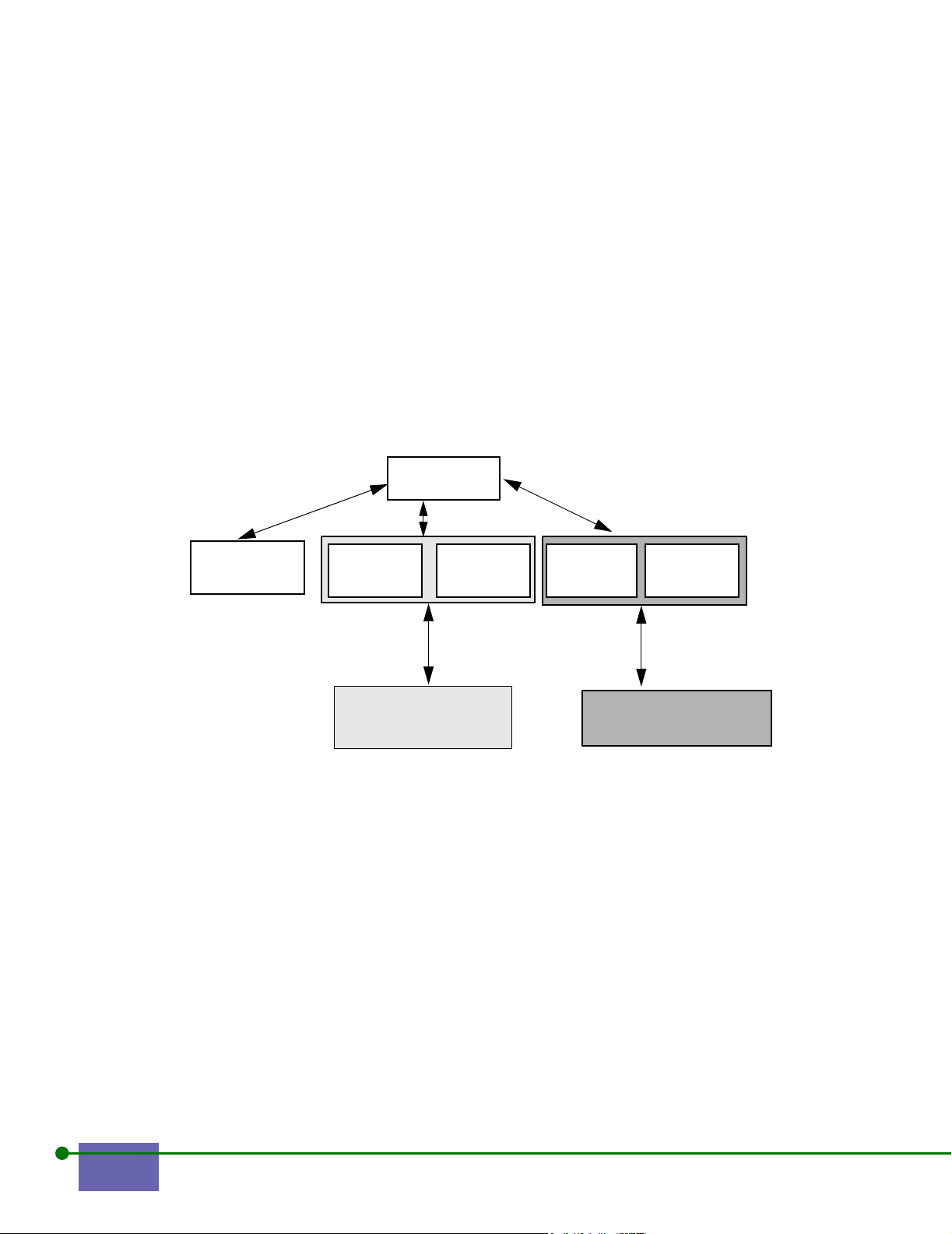
6.2.1 Two Simple Rights Examples
The following simple examples explain at a high level why you might want to
change rights. First, there is the visiting professor who comes to Cold Creek
University for the month of January. Second, the contractors who are implementing
a new student database for Cold Creek University need extra hours to complete
the project on schedule.
Example 1: Visiting Professor
Professor Lupine is visiting Cold Creek for the month of January to share his
research findings. Figure 6-2 shows a conceptual illustration of his rights compared
to those of usual professors at this location.
Location:
Cold Creek U
Where:
Chemistry
Bldg.
When:
When=
Usual
Group:
Usual
When:
Special
January 02
Group:
visitor
Appointed Faculty and
staff
Figure 6-2. Example 1: Visiting Professor
Visiting Professor Lupine
In Figure 6-2, Professor Lupine has access to the university network for the month
of January. He is part of the Professor group in the Chemistry building, but his
rights are limited based on when, while the usual professors have unlimited rights.
Example 2: Contractors with Extended Hours
The contractors who are completing implementation of a new student database
need access for additional hours. Figure 6-3 on page 6-5 shows the conceptual
overview of giving special database contractors extended hours.
6-4 Configuring the Rights Manager
Page 79
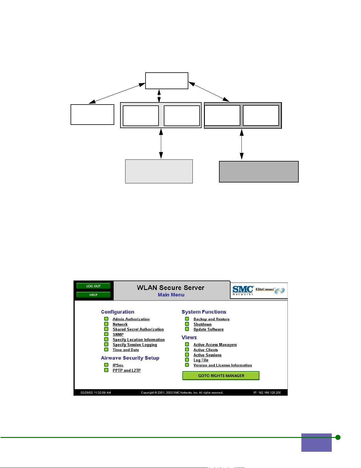
Location:
Cold Creek U
Where:
Admin office
Bldg.
When:
When=
Usual
Group:
Usual
General Contractors
Figure 6-3. Contractor Example
6.3 Getting to the Rights Manager
To go to the Rights Manager:
Step 1. Set your browser to the IP address or hostname of the WLAN Secure
Server or WLAN Access Manager.
Step 2. Press Enter.
Step 3. The Main Menu appears, as shown in Figure 6-4.
When:
8AM midnight
Group:
ORA
ORA Database
Contractors
Figure 6-4. Main Menu
EliteConnect WLAN Security System User Manual 6-5
Page 80

Note: Any system connected through one of the WLAN Access Manager’s ports can access the
web interface through the 42.0.0.1 IP address for initial system configuration.
Step 4.
The Home screen for the Rights Manager shows each user and its MAC address,
the Where, which is the WLAN Access Manager or the WLAN Access Manager
plus its port, the client IP Address, and the date and time that the client’s rights
expire.
Click Goto Rights Manager.
The Rights Manager screen appears, as shown in Figure 6-5.
Figure 6-5. Home Rights Manager
6.4 Changing Rights Associated with Locations
A Location is a group of Wheres, and some set of rights associated with the
location itself. A Where is a WLAN Access Manager or a WLAN Access Manager
port or a specific client. Locations are also associated with Whens, the times that
the location is available to groups of clients. See Changing the Time that a Group
is Valid for more information on changing the times associated with a group.
6.4.1 Why Change Rights
You must configure the initial rights that are associated with a location to enable
the SMC WLAN Secure Server. After configuring initial rights, you might need to
add locations, modify the rights associated with a location, or delete locations
because the locations or the functions housed in the location might change.
6-6 Configuring the Rights Manager
Page 81

As an example, a room that was once used only for college professors might
become a location used for graduate student’s thesis demonstrations to defend
their research. In this example, you might want to limit access to only graduate
students so that only these students can use network resources.
6.4.2 Adding a Location
To add a lo ca ti on:
Step 1. From the Rights Manager screen, click Locations.
Figure 6-6. Rights Manager
The Locations Manager appears, as shown in Figure 6-7.
Figure 6-7. Locations Manager
EliteConnect WLAN Security System User Manual 6-7
Page 82

Step 2. Click New Location.
The Location Editor appears, as shown in Figure 6-8 on page 6-8.
Figure 6-8. Locations Editor
Step 3. Type a loc at io n n ame.
Step 4. Add or change the Where:
a. Click New under Where to add a new WLAN Access Manager. See
Adding a WLAN Access Manager.
b. Click Edit under Where to change the properties of an existing WLAN
Access Manager. See Changing WLAN Access Manager Rights.
Note: You must have at least one Where.
Step 5.
Add or change the When: see Section , Changing the Time that a Group
is Valid.
6-8 Configuring the Rights Manager
Page 83

Note: If you leave When blank, it is available all of the time.
Step 6.
Add or change Groups: see Changing Group Properties.
a. Click New under Group to add a new group; see Adding a New
Group.
b. Click Edit under Group to change a groups’s rights; see Modifying a
Group’s Rights.
Note: All groups are disallowed except for those that you specifically allow.
Step 7.
Click NAT for this location, if applicable.
NAT determines if this location uses Network Address Translation for IP
addresses. The default is enable NAT; you must deselect NAT to use a
specified IP address.
Step 8. Type the Maximum number of users.
The maximum number of users permitted to use this location; the default
is unlimited.
Step 9. Click to disable or allow Encryption at this location.
Step 10. Choose whether to use L2TP and IPsec, IPSec, or PPTP.
Step 11. Click either:
a. Encryption allowed but not required
b. Require Encryption
c. Require Encryption except for: choose from the list of groups.
You can choose one or more of these groups.
Step 12. Click Enable PPTP/L2TP Authentication.
This box enables PPTP and L2TP authentication for this location.
Note: you might see No PPTP authentication realm defined with a radio
button indicated on, which means you cannot enable PPTP authentication
for this location until you create a PPTP realm.
Step 13. Choose a Realm.
If you have not yet created a realm, the default realm appears.
PPTP/L2TP Authentication Realm is the authentication realm that you
create. See Enforcing Authentication.
Step 14. Type and confirm the Shared Secret.
The shared secret is the shared secret for the enterprise network. The
shared secret is used instead of a PPTP realm. When selected, the user’s
password is compared with the shared secret to determine if the user is
authorized to create a PPTP tunnel.
Step 15. Type the Minimum session key length.
The minimum key length for the session key to encrypt a session; the
default value is 128 bits; alternate value is 40 bits.
EliteConnect WLAN Security System User Manual 6-9
Page 84

Step 16. Click to enable either MS-CHAP v2 or to enable MS-CHAP or MS-CHAP
v2.
Step 17. Click Update.
The Locations Editor now shows Music in the Location Name textbox, as shown in
Figure 6-9.
New Location Added
Figure 6-9. Location Editor With New Location to be Added
6-10 Configuring the Rights Manager
Page 85

6.4.3 Modifying a Location
You can modify the following location attributes: its name, the ports in use, the
times, groups, and other options that allow it to be available for use.
To modify the characteristics of a location:
Step 1. In the Location Manager, as shown in Figure 6-7 on page 6-7, click the
location name that you want to modify.
The Location Editor appears, as shown in Figure 6-10.
Figure 6-10. Location Editor
Step 2. You can change the Where, When, Allowed Groups, or Options.
• You can change Where; see Modifying a WLAN Access Manager.
• You can change When: see Changing Group Properties.
• You can change the Allowed Groups: see Changing Group Properties.
Step 3. Click Update.
EliteConnect WLAN Security System User Manual 6-11
Page 86

6.4.4 Deleting a Location
To delete a location:
Step 1. Click a Location that you want to delete from the Location Editor, as
shown in Figure 6-11.
Figure 6-11. Location Manager with a Location to be Deleted
Step 2. Click Delete.
The Delete Confirmation Screen appears, as shown in Figure 6-12 on page 6-13.
6-12 Configuring the Rights Manager
Page 87

Figure 6-12. Delete Location Confirmation
Step 3. If you are sure you want to delete this location, click Yes. Otherwise, click
No.
6.4.5 Changing WLAN Access Manager Rights
You might want to add, change, or delete rights associated with a WLAN Access
Manager if your environment has changed. For example, you might want to add a
WLAN Access Manager to handle increased network traffic in a meeting room. You
might want to modify the hours that a WLAN Access Manager supports if you
start offering night classes. You might delete a WLAN Access Manager’s rights if
you are closing the nearby area for renovation.
Adding a WLAN Access Manager
To add a WLAN Access Manager:
Step 1. Click Locations.
The Location Manager appears, as shown in Figure 6-13 on page 6-14.
EliteConnect WLAN Security System User Manual 6-13
Page 88

Figure 6-13. Location Manager
Step 2. Click New Location to add a WLAN Access Manager from the Locations
Manager menu.
The Locations Editor appears, as shown in Figure 6-14 on page 6-15.
6-14 Configuring the Rights Manager
Page 89

Figure 6-14. Location Editor
Step 3. Click New under Where.
The Where Editor appears, as shown in Figure 6-15.
EliteConnect WLAN Security System User Manual 6-15
Page 90
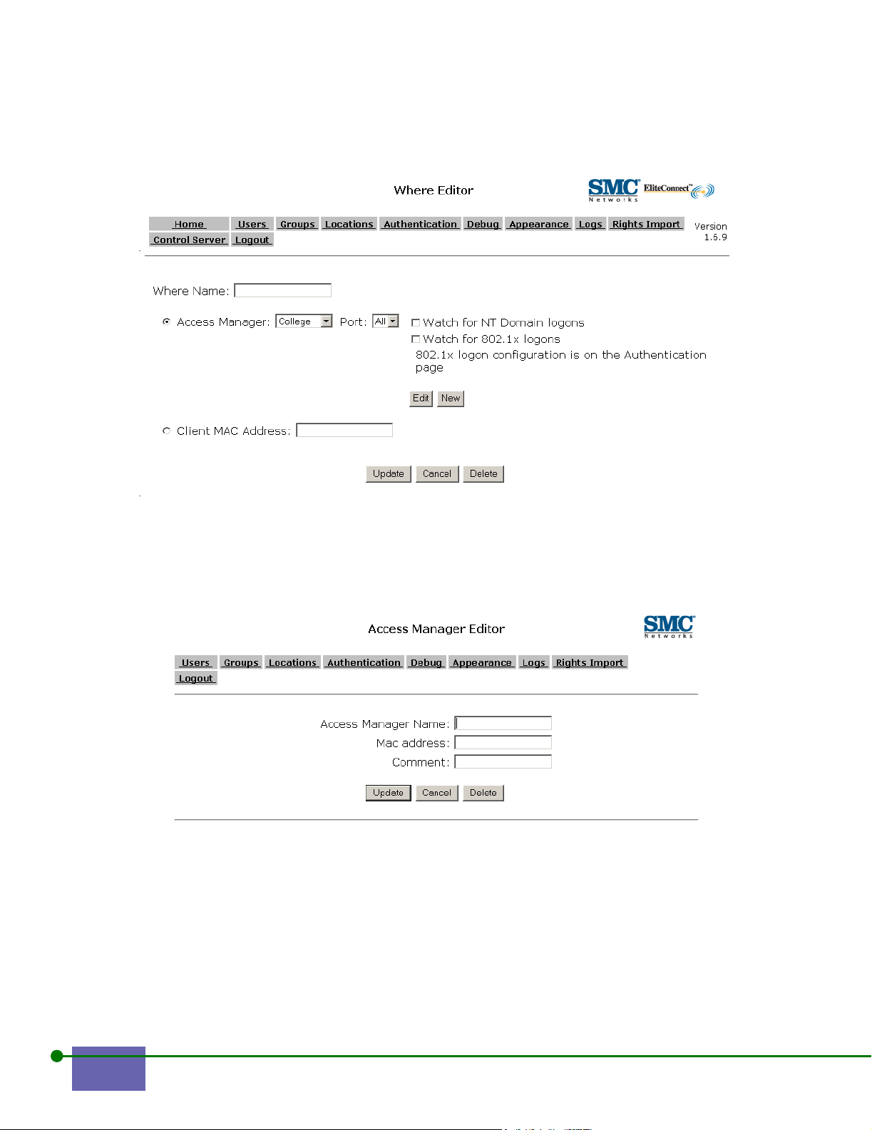
Figure 6-15. Where Editor
Step 4. Click New to add a new WLAN Access Manager.
The WLAN Access Manager Editor appears, as shown in Figure 6-16.
Figure 6-16. WLAN Access Manager Editor
Step 5. Type the WLAN Access Manager Name.
Step 6. Type the MAC address.
You can find the MAC address in the WLAN Access Manager Version and
License screen.
Step 7. Optionally, type a comment.
6-16 Configuring the Rights Manager
Page 91
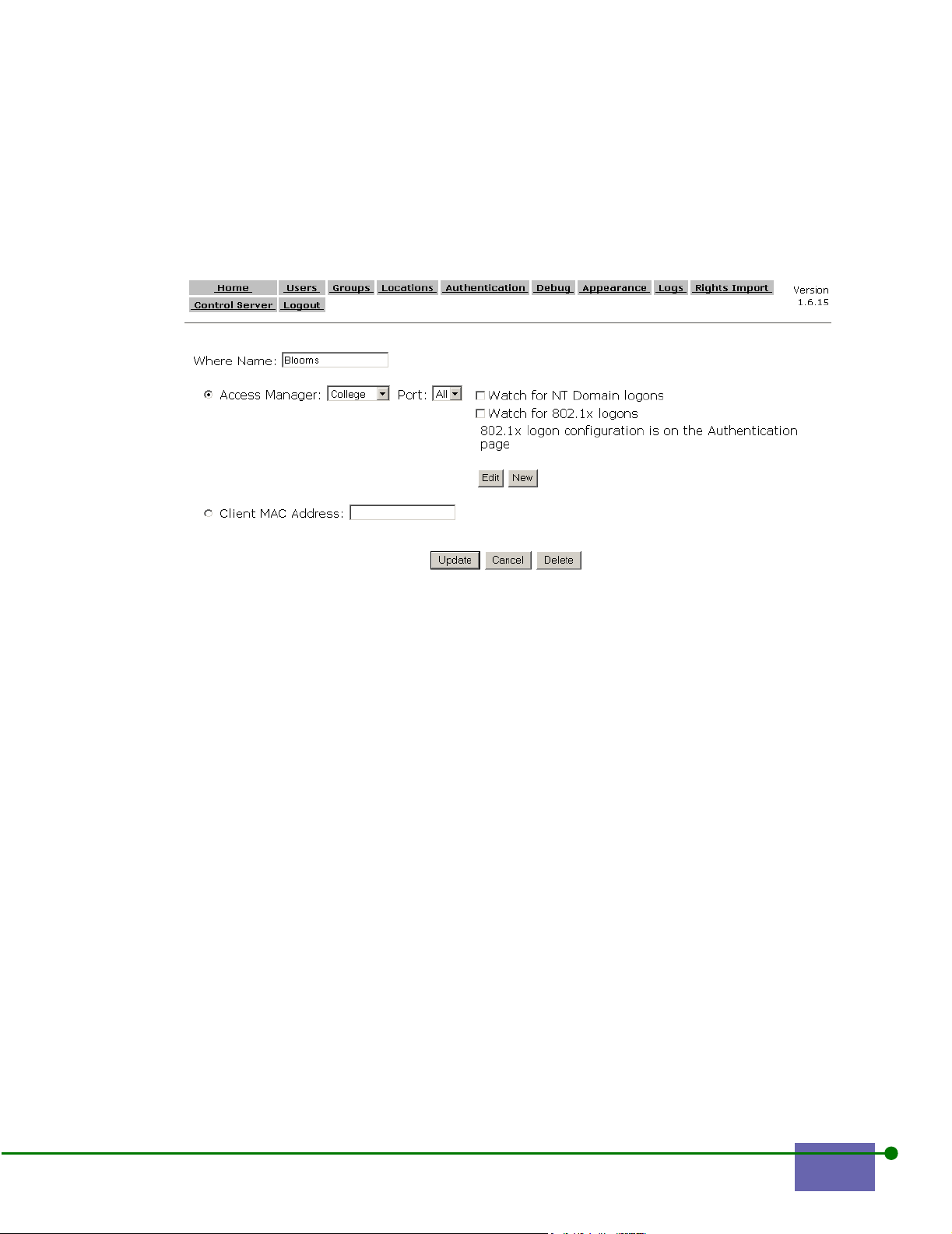
Step 8. Click Update to create a new WLAN Access Manager.
The Where Editor appears with your new WLAN Access Manager, as
shown in Figure 6-17.
Step 9. Type a name for your Where.
Figure 6-17. Where Editor with the New WLAN Access Manager
Step 10. Click Update.
The Location Editor appears, as shown in Figure 6-18 on page 6-18.
Step 11. Click the Where you created.
EliteConnect WLAN Security System User Manual 6-17
Page 92

N
ew Where
Figure 6-18. Location Editor with New Where Added
Step 12. Click Update.
6-18 Configuring the Rights Manager
Page 93
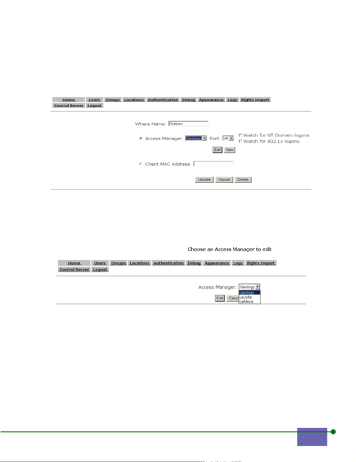
Modifying a WLAN Access Manager
To modify a WLAN Access Manager
Step 1. Go to the Where Editor, as shown in Figure 6-19.
Figure 6-19. Where Editor with Graham and Geology
Step 2. Click Edit.
The Choose a WLAN Access Manager to Edit screen appears with the list
of the WLAN Access Manager at that location, as shown in Figure 6-20.
Figure 6-20. Choose WLAN Access Manager to Edit
Step 3. Click the WLAN Access Manager to edit.
The WLAN Access Manager appears, as shown in Figure 6-21 on page 6-
20.
EliteConnect WLAN Security System User Manual 6-19
Page 94
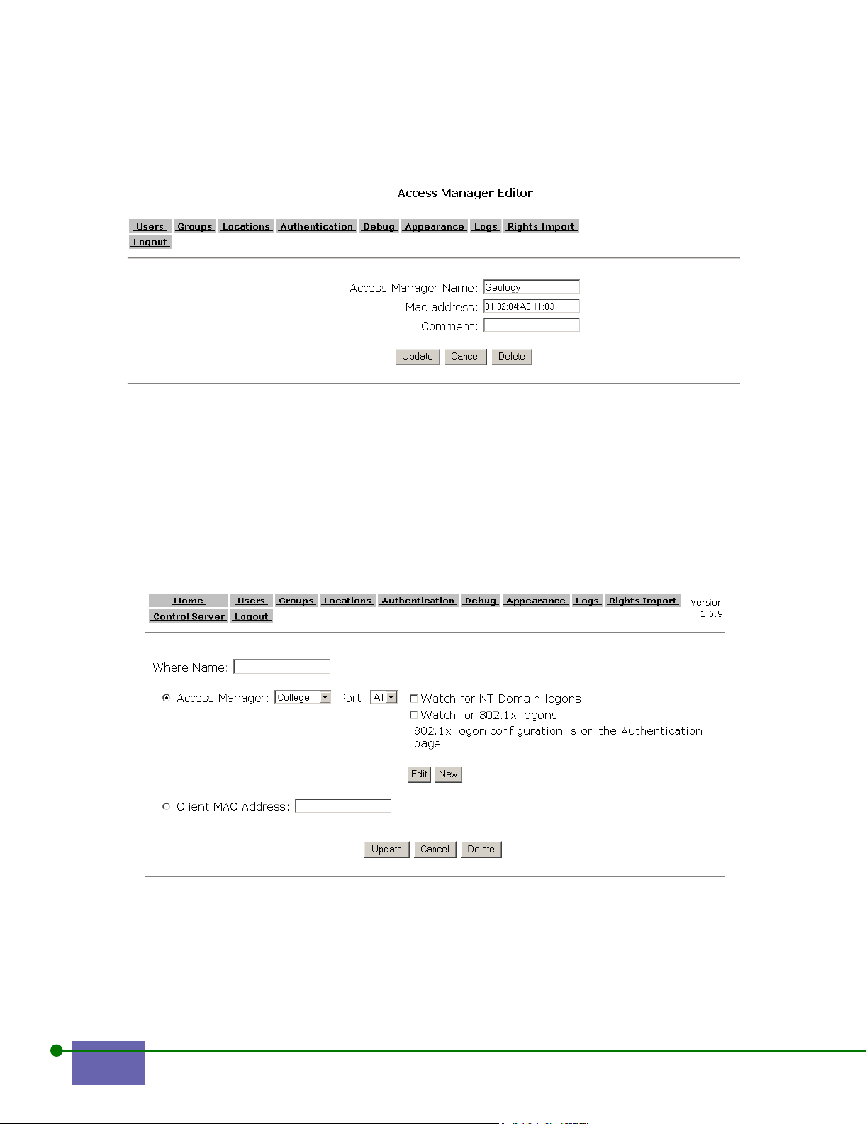
Figure 6-21. WLAN Access Manager Editor
Step 4. Change the MAC Address or comment as required.
Step 5. When you are done, click Update.
The WLAN Access Manager is modified or created if you changed the
WLAN Access Manager name.
Changing Other Where Properties
You can change other Where properties, as shown in Figure 6-22.
Figure 6-22. Where Editor
To chan ge Where properties:
• Click a specific port number or All to change the port number.
6-20 Configuring the Rights Manager
Page 95
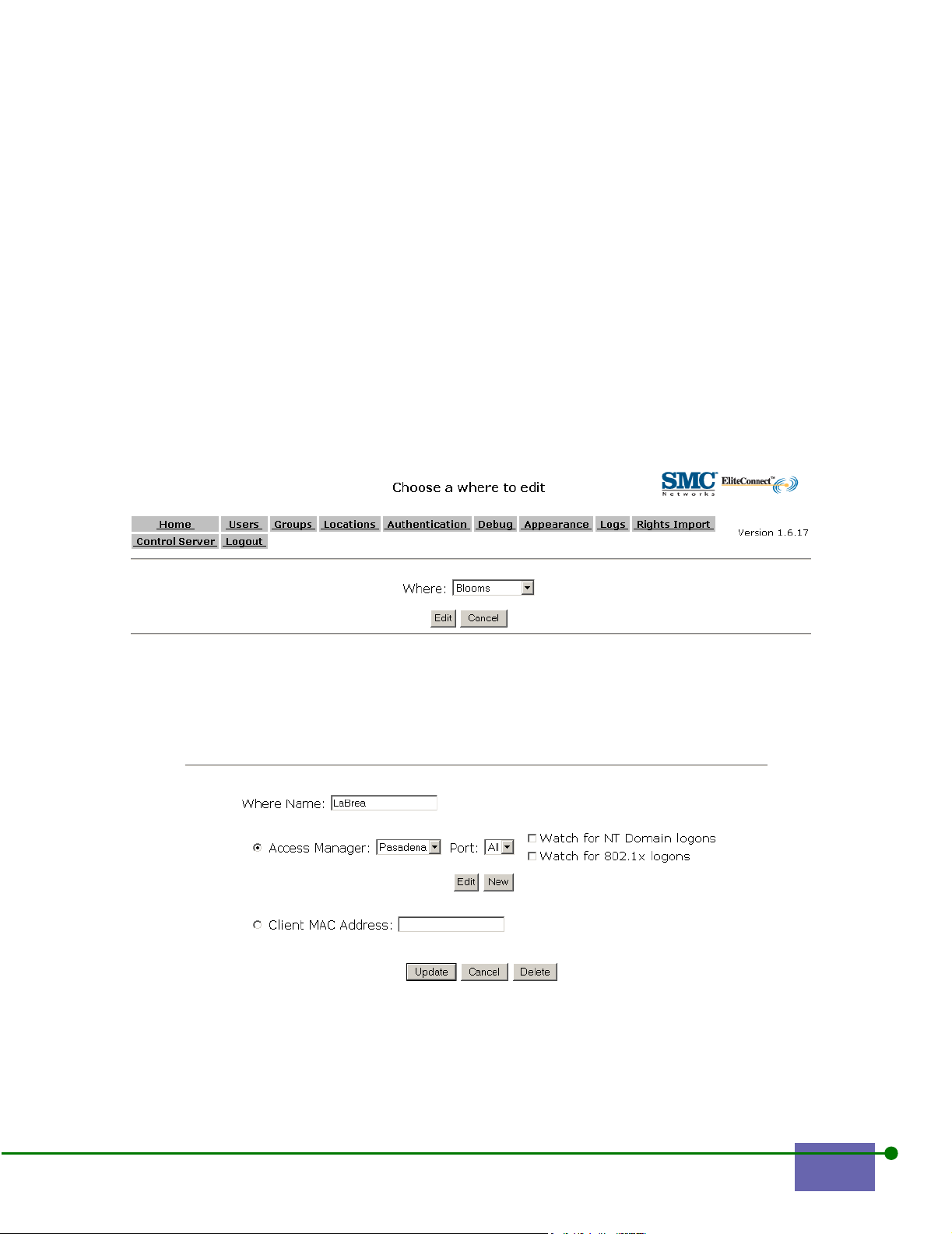
• Click the checkbox for the Watch for NT Domain logons or Watch for 802.1x
logons to interoperate with your enterprise environment.
• Type a new Client MAC address.
See Section C.14, Example 9, Public Kiosk Location for an example of a client
MAC address.
Click Update.
Deleting a Where
To delete a Where:
Step 1. Click Edit under Where to select the WLAN Access Manager from the
Location Editor.
The Choose a Where to edit screen appears, as shown in Figure 6-23.
Figure 6-23. Choose a Where to Edit
Step 2. Choose the Where to edit from the list.
The Where Editor appears with the name of the WLAN Access Manager
you selected, as shown in Figure 6-24.
Figure 6-24. Where Editor with Where Name Selected
Step 3. Click Delete.
The Delete Confirmation screen appears, as shown in Figure 6-25.
EliteConnect WLAN Security System User Manual 6-21
Page 96

Figure 6-25. Where Delete Confirmation Screen
Step 4. To delete the Where, click Yes. Otherwise, click No.
6.5 Changing Group Properties
Users can be members of one or more groups. Making a user a member of a group
is the basic way to deliver a set of rights for a collection of users. Group properties
include:
• group type, indicating the type of user
• valid times for the group (When)
• Allow rights
• Redirect rights
• Options
The Rights Manager has the following standard groups:
• Logon: users are users who have not yet logged in and have not been
authenticated
• Guest: users who have guest rights allocated
• Normal: authenticated users with the rights allocated to their group; this is the
base group for all authenticated users at the location.
• User Group: the base group in which rights are allocated to all authenticated
users at the specified location.
See Section 6.6.2, Modifying a User’s Characteristics for more information.
You can add or delete a group, or modify a group’s properties.
6.5.1 Adding a New Group
Step 1. Click Groups.
The Groups Manager screen appears, as shown in Figure 6-26.
6-22 Configuring the Rights Manager
Page 97
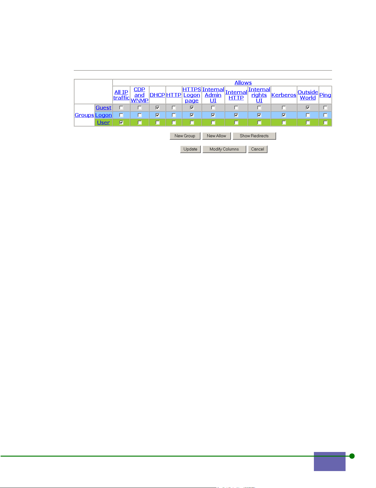
Figure 6-26. Groups Manager
Step 2. Click New Group.
Step 3. Type the Group Name that you want to add, in this example, Contractors,
as shown in Figure 6-27 on page 6-24.
EliteConnect WLAN Security System User Manual 6-23
Page 98

Figure 6-27. Group Editor with Contractors
Step 4. Check the appropriate Group Type.
See Modifying a User’s Characteristics.
Step 5. Choose specific times when this group is allowed access. Under Valid
Times, click New.
The When Editor appears, as shown in Figure 6-31 on page 6-29. Click the
appropriate times these set of rights are valid or none if they are always
valid. See Changing the Time that a Group is Valid.
Step 6. Pick the set of rights for the group.
Table 6-1 explains the entries in the Group Editor.
6-24 Configuring the Rights Manager
Page 99

Table 6-1 Group Editor Rights Entries
Entry Explanation
Group Name The name of a group you want to create, modify, or delete
Group Type Either Normal, Guest, Logon, or Implicit Users
Valid Times When these rights are valid
Has Rights Select each right that you want members of this group to have
Match an NT Group Name Use these rights when a user logs into a Matching NT domain.
NAT Whether NAT addresses are enabled.
Static IP allowed Whether static IP addresses are enabled or obtain the IP
address from DHCP.
Override max user
restrictions
Max concurrent logons per
user
Linger Seconds How long to wait before logging off after the client
Expire Seconds How long these rights are in effect.
Enable HTTP Proxy When checked, the HTTP Proxy is enabled
Use a browser cookie to
optimize logoffs
HTTP Proxy IP Address When Enable HTTP Proxy is checked, the HTTP Proxy IP
HTTP Proxy Port When Enable HTTP Proxy is checked, the HTTP Proxy IP Port
Whether any member of this group can override the maximum
amount of users of a group at a location.
The maximum number of logons each user can have; the
default is UNLIMITED.
disassociates. The default is 300.
When checked, a browser cookie helps with logoffs saved
during logon.
Address.
Number.
Note: You can choose multiple Allows, Redirects, and valid times for a group. Your web
browser determines how you select individual rights. Using Microsoft Internet
Explorer™, for example, hold the Control key while you highlight the individual rights.
Using Netscape Navigator, hold down the Shift key while you select individual rights.
Step 7.
When you are done click Update.
The Group Manager screen appears with Contractors added as a group, as
shown in Figure 6-28 on page 6-26.
EliteConnect WLAN Security System User Manual 6-25
Page 100
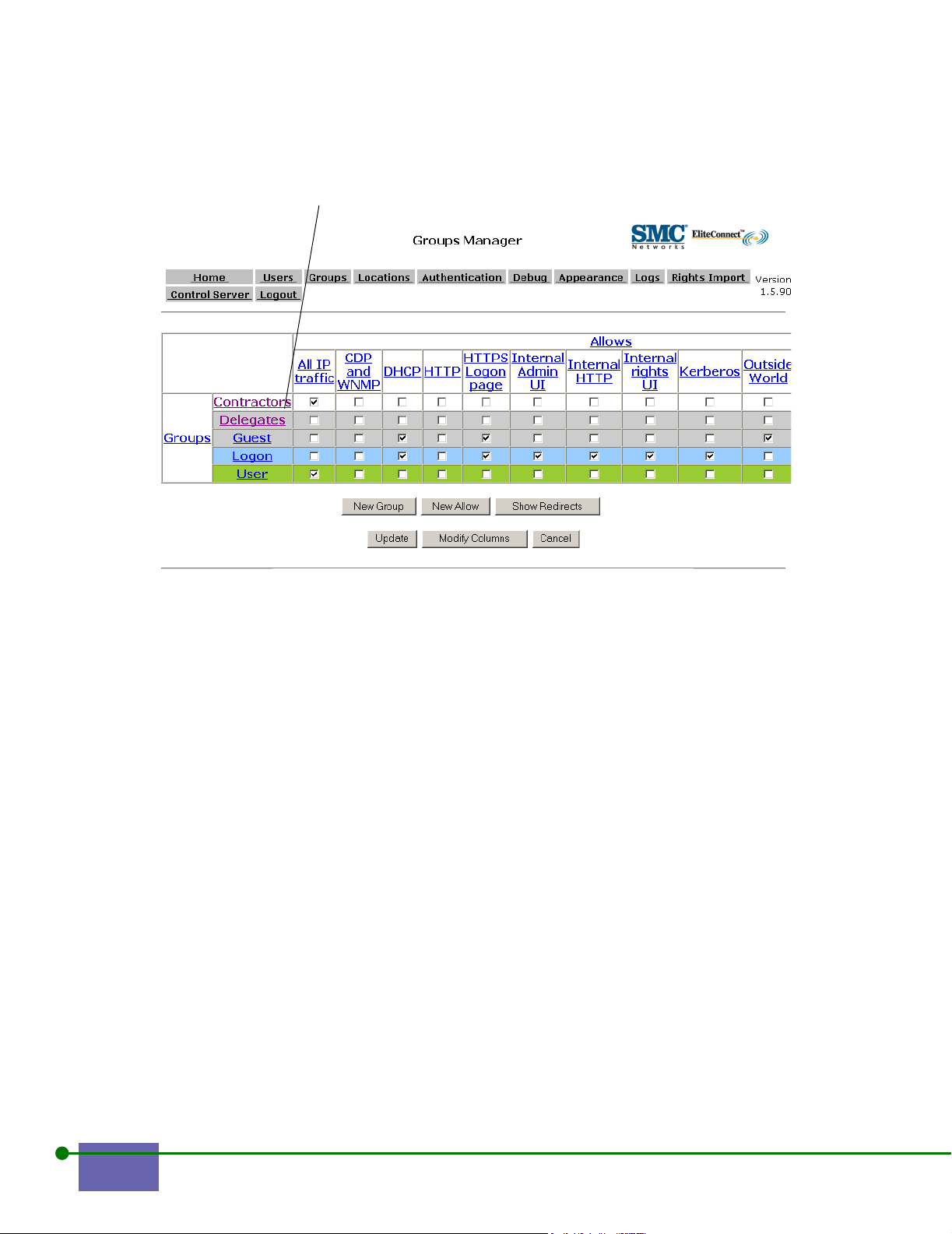
Contractors Added
Figure 6-28. Groups Manager With Group Contractors Added
6.5.2 Modifying a Group’s Rights
This section describes how to modify a group that was previously created by:
• Initially configuring the times when a group can access
• Changing the times when the group can access
• Changing the Allows that appear on the Group Manager screen
Note: If you leave When blank, it is available all of the time.
Initially Configuring Valid Times or Whens
To create valid times for a group:
Step 1. In the Group Manager screen, click the group you have created, in this
example, Contractors, as shown in Figure 6-29 on page 6-27.
6-26 Configuring the Rights Manager
 Loading...