

Page 1

Page 2

19" Rack-mount
12-Slot Standalone
Media Converter Chassis
User's Manual
December 2003
Page 3

TABLE OF CONTENTS
Introduction . . . . . . . . . . . . . . . . . . . . . . . . . . . . . . . 1
About This Guide . . . . . . . . . . . . . . . . . . . . . . . . . . . . . . . . . . . .1
Welcome . . . . . . . . . . . . . . . . . . . . . . . . . . . . . . . . . . . . . .1
Purpose . . . . . . . . . . . . . . . . . . . . . . . . . . . . . . . . . . . . . . 1
Terms/Usage . . . . . . . . . . . . . . . . . . . . . . . . . . . . . . . . . .1
Features . . . . . . . . . . . . . . . . . . . . . . . . . . . . . . . . . . . . . . 1
Package Contents . . . . . . . . . . . . . . . . . . . . . . . . . . . . . . 2
Hardware Description . . . . . . . . . . . . . . . . . . . . . . . 3
Product Overview . . . . . . . . . . . . . . . . . . . . . . . . . . . . . . . . . . . . 3
Product Outlook . . . . . . . . . . . . . . . . . . . . . . . . . . . . . . . . . . . . . 4
Installation . . . . . . . . . . . . . . . . . . . . . . . . . . . . . . . . 5
Installing the brackets . . . . . . . . . . . . . . . . . . . . . . . . . . . . . . . . . 5
Affixing brackets . . . . . . . . . . . . . . . . . . . . . . . . . . . . . . . . 6
Installing the converter . . . . . . . . . . . . . . . . . . . . . . . . . . . . . . . .7
Power Supply . . . . . . . . . . . . . . . . . . . . . . . . . . . . 11
Rack Kit . . . . . . . . . . . . . . . . . . . . . . . . . . . . . . . . . 13
LEDs Indicators . . . . . . . . . . . . . . . . . . . . . . . . . . . 15
Cooling . . . . . . . . . . . . . . . . . . . . . . . . . . . . . . . . . . 17
Technical Specifications . . . . . . . . . . . . . . . . . . . 19
Compliances . . . . . . . . . . . . . . . . . . . . . . . . . . . . . . i
Legal Information and Contacts . . . . . . . . . . . . . . v
i
Page 4

About This Guide
Welcome
INTRODUCTION
Thank you for choosing the 19" Rack-mount 12-slot Standalone
Media Converter Chassis. This device provides power and
protection for media converters in one reliable package.
Purpose
This guide discusses how to setup and install your 19"
Rack-mount 12-slot Standalone Media Converter Chassis.
Terms/Usage
In this guide, the term "Chassis" (first letter upper case) refers
to your 19" Rack-mount 12-slot Standalone Media Converter
Chassis, and "chassis" (first letter lower case) refers to other
chassis.
Features
• Supports two load sharing, hot swappable power supplies.
• Three high volume cooling fans ensure perfect operating
environment.
• Status panel with fan and slot power status LEDs.
• Supports slot power isolation – ensures each slot
is electrically isolated from the next.
• Supports 10/100/1000Base, Copper, Fiber.
• Single/Multi-mode, ST, SC, connectors.
1
Page 5

Introduction
• Avoids network downtime and protects your converter
investments.
• Ideal for mission critical networks such as Large Office
Complex, Banks, Military etc.
• High quality 19" Rack-mount Chassis.
• Supports up to 12 media converters.
Package Contents
• One 12-slot Media Converter Chassis.
• One power supply.
• One power supply cable.
• 19" rack mounting kit.
• 12 blank panels (fitted).
• 24 Converter mounting panels.
• Four self-adhesive pads.
• Spare screws.
• Spare fuses.
• One user's manual.
2
Page 6

HARDWARE DESCRIPTION
Product Overview
The Converters Chassis offers the user a dedicated and secure
environment for multiple media conversion applications. It also
allows the user to utilize existing and new media converters
either in the rack or in a stand-alone installation.
Flexibility
The Chassis supports up to 12 media converters covering
10Base-T, 10Base-FL, 100Base-TX and 100Base-FX, Gigabit
1000Base-T, Gigabit SX/LX, conversion. In addition, both Multimode and Single Mode options are supported too.
Reliability
The Chassis also supports two high quality hot swappable power
supplies. Either power unit can be removed without disturbing
the Chassis' operation – offering total efficiency, maximum
redundancy and minimum down time. Each converter is supplied
from a common shared power bus – but as an added precaution,
each is individually protected in the event of a problem on the
or from the power supply. Each converter can also be changed
without powering down.
bus
Functionality
The Chassis was carefully designed to offer a lifetime of operation
Incorporated into the Chassis are three long-life cooling fans to
ensure a cool operating environment. The Chassis also features
an LED status panel. Each fans and converter is monitored and
connected to the LED status panel. This indicates that power
is supplied to each converter and that the Fans are functioning
correctly. The power supplies also feature a "trigger guard" to
prevent the supply from being accidentally switched off.
.
3
Page 7
Hardware Description
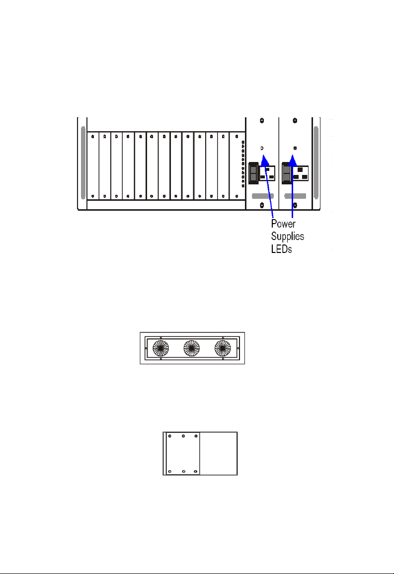
Product Outlook
Front View with 12 blank slots and two power supplies
Rear View showing 3 cooling fans
Side View with rack-mount assembly fitted
4
Page 8

INSTALLATION
In this chapter, we will take a look at how to install converters into
the Chassis and the different options available for placement of the
Chassis system within its operating environment. First, it is important
to unpack the Chassis and ensure that all the components listed
on page 2 "Package Contents" are present. In some cases, the
Chassis may come complete with certain converters already
installed. You can either install the converters first and then
the Chassis, or you can install the Chassis first and then the
converters. We recommend that you do the latter as it is more
convenient.
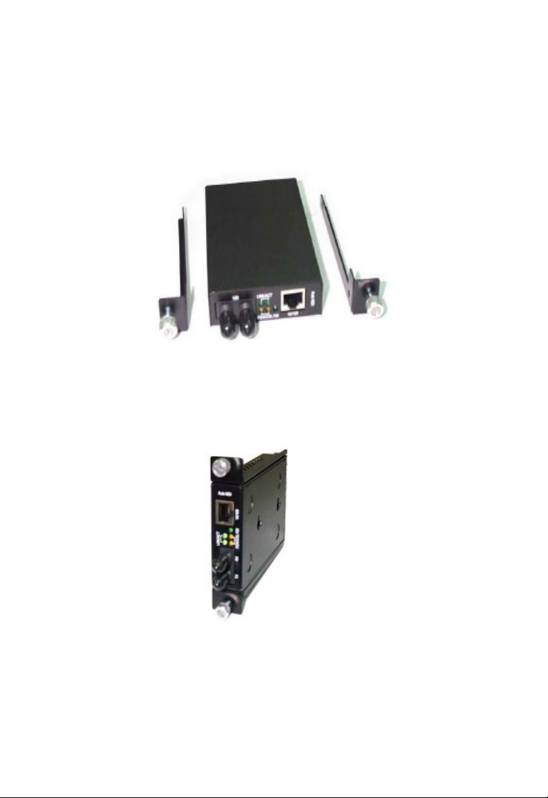
Installing the brackets
All the converters are made using a standard case. This allows it
to fit into the Chassis with ease. The converters can be mounted
directly into the Chassis without using the supplied brackets but
we strongly advise against this. We have supplied special brackets
that easily attaches to the converters. This allows for the secure
placement of the converters into the Chassis. The bracket also
seals off the front of the Chassis and allows it's cooling system
to function correctly.
5
Page 9
Installation
Affixing brackets
Step 1. Using a Phillips screwdriver, remove two screws
from the side panels on the converter.
Step 2. Place the converter and brackets on a flat horizontal
surface as illustrated above. Secure the brackets by
replacing the screws
.
Ensure that the rails are flush-mounted with the underside
of the converter. The converter is now ready for loading into
the Chassis.
6
Page 10

Installing the converter
Installing the converter
Once the converters have been attached to the brackets, it can be
installed into the Chassis. The converters can go into the Chassis
in any order and can be placed in any available slot. Special care
must be taken to ensure the correct mating of the power connector.
Choose an available slot and align the converter so that it fits
between the upper and lower guide rails.
Warning
Always ensure that the converter's power socket
is positioned at the base of the Chassis.
Warning
Never force the converter into the Chassis – check
power socket position and alignment.
12-slot Media Converter Chassis
If necessary, you may gently move the converter up & down
or left & right to ensure that the plug and socket align correctly.
7
Page 11

Installation
Installing the Chassis
The Chassis is made from a combination of steel and aluminum
and is very sturdy in design. This allows the Chassis to be installed
in the following ways.
Rack-mount
The Chassis is built to established EIA Standards and as such will
fit into any 19" EIA designed rack. Refer to the section "Rack Kit".
Wall-Mount
The Chassis can be mounted separately on a wall with the use of
a shelf. This should be securely mounted on a suitable structure
and must be able to hold at least 15 kg. The shelf should also be
big enough to accommodate the Chassis whilst still offering space
for adequate ventilation.
8
Page 12

Installing the converter
Desktop
The Chassis can be situated on any suitable desktop. Simply
attach the adhesive pads to the base of the Chassis and position
where suitable, again, keep adequate space for ventilation.
9
Page 13

POWER SUPPLY
The Chassis is normally supplied with one redundant, hot –
swappable power supply as shown below. The design of the power
system is based around flexibility and maximum redundancy. For
normal operation, one power supply is sufficient to operate with
12 converters fully loaded simultaneously. However, for critical
applications, installing two power supplies is recommended.
During 2-power operation, both power supplies will be switched
on and will share the currant load between them. In the event
that a power supply should fail, the other supply will take 100%
of the load. This will happen instantaneously and will have no
adverse effects on the operation of the Chassis. Similarly, if a
power supply is removed for servicing, it can be switched off and
removed while the Chassis continues to function normally.
The Chassis shown as supplied with one Hot-swappable,
Redundant 75Watt Power Supply
11
Page 14

Power Supply
The Chassis shown as supplied with two Hot-swappable,
Redundant 75 Watt Power Supplies
To remove the Power Supplies from the Chassis, simply undo
the securing screws, and then pull the power supply unit out
from the Chassis by the handles.
Warning
Always exercise Caution when removing supplies.
Always switch Power Supply off before removing.
Always remove Power Cable from Supplies before removing.
Do not touch Power Supply components after removal
they may hold residual electrical charges.
12
–
Page 15

RACK KIT
The Chassis comes with a 19" Rack Mounting Kit. This basically
comprises of two brackets and a set of screws. The brackets are
fitted to the Chassis via six screws. It is strongly recommended
that you use all six screws supplied with the Chassis. This will
ensure that stress is not unnecessary endured by the Chassis or
the brackets. Each bracket has EIA standard mounting holes and
is symmetrical so that either bracket can be used on either side
of the Chassis.
13
Page 16

LEDS INDICATORS
To enable the MIS personnel to establish the operational status of
the Chassis, a simple LED display panel is installed. Its simplicity
hides the fact that the Chassis employs a sophisticated power
distribution system. All converters are supplied from the one hotswappable Power Supply. However, this is where their common
connection stops. Each slot has its own protection system that
isolates each converter from any problems that might occur with
either the power supplies or another faulty converter. This offers
the best possible protection to your investment in the various
media converters.
Fan Indicator LED's
These should illuminate under
normal operating conditions.
Slot Power LED's
These will illuminate when converters
are loaded into the Chassis' slot. The
LEDs will extinguish if converters are
not installed or if there is a problem
with the power supply.
15
Page 17

COOLING
The Chassis holds up to two power supplies and twelve media
converters, so it needs to have reliable form of cooling. This
Chassis has three fans located at the rear of the Chassis, and
draws air into the Chassis. Each fan is connected to the Status
Monitoring Panel on the front of the Chassis. Even with only one
fan working, the Chassis is capable of operating under normal
operating temperatures. For the purpose of cleaning, the Fan
panel assembly can be removed for periodic maintenance. Switch
both power supplies off, and remove the six securing screws.
Disconnect the three power cables supplying DC to the fans. The
fans can then be cleaned with a dry cloth. Replace the fan panel
by reversing the above procedure.
17
Page 18

TECHNICAL SPECIFICATIONS
Chassis Specs
Capacity: 12 slots – up to 12 converters
Chassis: Aluminium, Steel
Power: Up to two load sharing, hot swappable power supplies
LEDs: 3 Red for fan status,
12 Green for slot power status,
1 Red for each power supply.
Cooling: Three 42.5 cfm rear-mounted fans
Dimension: 440 x 290 x 133 mm (L x W x H)
(EIA 3U)
Weight: 7.6 kg (with one power supply)
13 kg (loaded with 12 standalone converters)
Power Supply Specs for AC
AC input: 100 ~ 240V AC @ 47 ~ 63Hz
DC Output: Norm. +12V, Min. +11.88V, Max +12.12V, 75Watts
Load: Min. OA, Full. 6.4A
Total Reg.: +/- 1.0%, Rip. 120mV, Load 2.0%, Line 0.5%
Overload Protection: All outputs protected against short circuit
conditions, automatic recovery
Over volts Protection: Output level exceeding + 13.2V causes
shutdown – automatic recovery
19
Page 19

Technical Specifications
Temperature: Operating: 0×C ~ 50×C,
Storage: -55×C ~ 85×C
EMI: FCC Part 15 Class A
Safety: UL / cUL / TUV Approved
Power Supply Specs for DC -48V
DC input: -48V ±10%
DC Output: Norm. +12V, Min. +11.76V, Max +12.24V, 75Watts
Load: Min. OA, Full. 6.4A
Total Reg.: +/- 2.0%, Rip. 120mV, Load 2.0%, Line 1.0%
Overload Protection: Output protected against short circuit
conditions, automatic recovery
Over volts Protection: Output level exceeding + 13.2V
causes shutdown – automatic recovery
Temperature: Operation: 0×C ~ 50×C,
Storage: -55×C ~ 85×C
Fans Specs
Speed: 2510 rpm +/- 250, Delivery 42.5ft3 Per Min.
Noise Level: 36.5dB(A) (each fan)
Temperature: Operation: 10×C ~ 50×C
Storage: 40×C ~ 70×C
Bearing: Precise Ball Bearing
Safety: UL / cUL / TUV Approved
20
Page 20

COMPLIANCES
FCC – Class A
This equipment has been tested and found to comply with the limits for a
Class A digital device, pursuant to Part 15 of the FCC Rules. These limits
are designed to provide reasonable protection against harmful
interference in a residential installation. This equipment generates, uses
and can radiate radio frequency energy and, if not installed and used in
accordance with instructions, may cause harmful interference to radio
communications. However, there is no guarantee that the interference
will not occur in a particular installation. If this equipment does cause
harmful interference to radio or television reception, which can be
determined by turning the equipment off and on, the user is encouraged
to try to correct the interference by one or more of the following measures:
• Reorient the receiving antenna
• Increase the separation between the equipment and receiver
• Connect the equipment into an outlet on a circuit different from that
to which the receiver is connected
• Consult the dealer or an experienced radio/TV technician for help
EC Conformance Declaration – Class A
SMC contact for these products in Europe is:
SMC Networks Europe,
Edificio Conata II,
Calle Fructuós Gelabert 6-8, 2o, 4a,
08970 - Sant Joan Despí,
Barcelona, Spain.
This information technology equipment complies with the requirements
of theCouncil Directive 89/336/EEC on the Approximation of the laws
of the MemberStates relating Electromagnetic Compatibility and 73/23/
EEC for electricalequipment used within certain voltage limits and the
Amendment Directive 93/68/EEC. For the evaluation of the compliance
with these Directives, the following standards were applied:
RFI Emission:
• EN 55022:1994/5/7 Class A
• Limit class A for harmonic current emission according to
N 61000-3-2/1995
i
Page 21

Compliances
• Limitation of voltage fluctuation and flicker in low-voltage supply
system according to EN 61000-3-3/1995
Immunity:
• Product family standard according to EN 55024:1998
• Electrostatic Discharge according to EN 61000-4-2:2001
(Contact Discharge: ±4 kV, Air Discharge: ±8 kV)
• Radio-frequency electromagnetic field according to EN 61000-4-3:1996
(80 - 1000 MHz with 1 kHz AM 80% Modulation: 3 V/m)
• Electrical fast transient/burst according to EN 61000-4-4:1996
(AC/DC power supply: ±1 kV, Data/Signal lines: ±0.5 kV)
• Surge immunity test according to EN 61000-4-5:1996
(AC/DC Line to Line: ±1 kV, AC/DC Line to Earth: ±2 kV)
• Immunity to conducted disturbances, Induced by radio-frequency
fields: EN 61000-4-6:1996 (0.15 - 80 MHz with 1 kHz AM 80%
Modulation: 3 V/m)
• Power frequency magnetic field immunity test according to
EN 61000-4-8:1993 (1 A/m at frequency 50 Hz)
• Voltage dips, short interruptions and voltage variations immunity
test according to EN 61000-4-11:1994 (>95% Reduction @10 ms,
30% Reduction @500 ms, >95% Reduction @5000 ms)
LV D:
• EN 60950 (A1/1992; A2/1993; A3/1993; A4/1995; A11/1997)
MDD:
• IEC 60601-1
Industry Canada – Class B
This digital apparatus does not exceed the Class B limits for radio noise
emissions from digital apparatus as set out in the interference-causing
equipment standard entitled "Digital Apparatus" ICES-003 of the
Department of Communications. Cet appareil numérique respecte les
limites de bruits radioélectriques applicables aux appareils numériques
de Classe B prescrites dans la norme sur le matériel brouilleur:
« Appareils Numériques » NMB-003 édictée par le ministère des
Communications.
ii
Page 22

Compliances
Safety Compliance
CSA/NRTL (C22.2.950, UL 1950)
EN60950, (IEC 950)
Wichtige Sicherheitshinweise (Germany)
1. Bitte lesen Sie diese Hinweise sorgfältig durch.
2. Heben Sie diese Anleitung für den späteren Gebrauch auf.
3. Vor jedem Reinigen ist das Gerät vom Stromnetz zu trennen.
Verwenden Sie keine Flüssigoder Aerosolreiniger. Am besten
eignet sich ein angefeuchtetes Tuch zur Reinigung.
4. Die Netzanschlu ßsteckdose soll nahe dem Gerät angebracht
und leicht zugänglich sein.
5. Das Gerät ist vor Feuchtigkeit zu schützen.
6. Bei der Aufstellung des Gerätes ist auf sicheren Stand zu achten.
Ein Kippen oder Fallen könnte Beschädigungen hervorrufen.
7. Die Belüftungsöffnungen dienen der Luftzirkulation, die das Gerät vor
Überhitzung schützt. Sorgen Sie dafür, daß diese Öffnungen nicht
abgedeckt werden.
8. Beachten Sie beim Anschluß an das Stromnetz die Anschlußwerte.
Verlegen Sie die Netzanschlußleitung so, daß niemand darüber fallen
9.
Es sollte auch nichts auf der Leitung abgestellt werden.
kann.
10. Alle Hinweise und Warnungen, die sich am Gerät befinden,
sind zu beachten.
11. Wird das Gerät über einen längeren Zeitraum nicht benutzt,
sollten Sie es vom Stromnetz trennen. Somit wird im Falle einer
Überspannung eine Beschädigung vermieden.
12. Durch die Lüftungsöffnungen dürfen niemals Gegenstände oder
Flüssigkeiten in das Gerät gelangen. Dies könnte einen Brand bzw.
elektrischen Schlag auslösen.
Öffnen sie niemals das Gerät. Das Gerät darf aus Gründen der
13.
elektrischen Sicherheit nur von authorisiertem Servicepersonal
geöffnet werden
14. Wenn folgende Situationen auftreten ist das Gerät vom Stromnetz
zu trennenund von einer qualifizierten Servicestelle zu überprüfen:
a. Netzkabel oder Netzstecker sind beschädigt.
.
iii
Page 23

Compliances
b. Flüssigkeit ist in das Gerät eingedrungen.
c. Das Gerät war Feuchtigkeit ausgesetzt.
d. Wenn das Gerät nicht der Bedienungsanleitung
entsprechend funktioniert oder Sie mit Hilfe dieser
Anleitung keine Verbesserung erzielen.
e. Das Gerät ist gefallen und/oder das Gehäuse
ist beschädigt.
f. Wenn das Gerät deutliche Anzeichen eines Defektes
aufweist.
15. Stellen Sie sicher, daß die Stromversorgung dieses Gerätes nach der
EN 60950 geprüft ist. Ausgangswerte der Stromversorgung sollten
die Werte von AC 7.5-8 V, 50-60 Hz nicht über oder unterschreiten
sowie den minimalen Strom von 1 A nicht unterschreiten. Der
arbeitsplatzbezogene Schalldruckpegel nach DIN 45 635 Teil
1000 beträgt 70dB(A) oder weniger.
iv
Page 24

LEGAL INFORMATION
AND
SMC's Limited Warranty Statement
SMC Networks Europe ("SMC") warrants its products to be free from
defects in workmanship and materials, under normal use and service, for
the applicable warranty term. All SMC products carry a standard 2 year
limited warranty from the date of purchase from SMC or its Authorized
Reseller. SMC may, at its own discretion, repair or replace any product
not operating as warranted with a similar or functionally equivalent
product, during the applicable warranty term. SMC will endeavour to
repair or replace any product returned under warranty within 30 days of
receipt of the product. As new technologies emerge, older technologies
become obsolete and SMC will, at its discretion, replace an older product
in its product line with one that incorporates these newer technologies.
The standard limited warranty can be upgraded to a 5 year Limited
Lifetime * warranty by registering new products within 30 days of
purchase from SMC or its Authorized Reseller. Registration can be
accomplished via the enclosed product registration card or online via
the SMC web site. Failure to register will not affect the standard limited
warranty. The Limited Lifetime warranty covers a product during the Life
of that Product, which is defined as a period of 5 years from the date of
purchase of the product from SMC or its authorized reseller.
All products that are replaced become the property of SMC. Replacement
products may be either new or reconditioned. Any replaced or repaired
product carries, either a 30-day limited warranty or the remainder of the
initial warranty, whichever is longer. SMC is not responsible for any custom
software or firmware, configuration information, or memory data of
Customer contained in, stored on, or integrated with any products
returned to SMC pursuant to any warranty. Products returned to SMC
should have any customer-installed accessory or add-on components,
such as expansion modules, removed prior to returning the product for
replacement. SMC is not responsible for these items if they are returned
with the product.
CONTACTS
v
Page 25

Legal Information and Contacts
Customers must contact SMC for a Return Material Authorization
number prior to returning any product to SMC. Proof of purchase may
be required. Any product returned to SMC without a valid Return Material
Authorization (RMA) number clearly marked on the outside of the package
will be returned to customer at customer's expense. Customers are
responsible for all shipping charges from their facility to SMC. SMC
is responsible for return shipping charges from SMC to customer.
WARRANTIES EXCLUSIVE: IF A SMC PRODUCT DOES NOT
OPERATE AS WARRANTED ABOVE, CUSTOMER'S SOLE REMEDY
SHALL BE REPAIR OR REPLACEMENT OF THE PRODUCT IN
QUESTION, AT SMC'S OPTION. THE FOREGOING WARRANTIES
AND REMEDIES ARE EXCLUSIVE AND ARE IN LIEU OF ALL OTHER
WARRANTIES OR CONDITIONS, EXPRESSED OR IMPLIED, EITHER
IN FACT OR BY OPERATION OF LAW, STATUTORY OR
OTHERWISE, INCLUDING WARRANTIES OR CONDITIONS OF
MERCHANTABILITY AND FITNESS FOR A PARTICULAR PURPOSE.
SMC NEITHER ASSUMES NOR AUTHORIZES ANY OTHER PERSON
TO ASSUME FOR IT ANY OTHER LIABILITY IN CONNECTION WITH
THE SALE, INSTALLATION, MAINTENANCE OR USE OF ITS
PRODUCTS. SMC SHALL NOT BE LIABLE UNDER THIS WARRANTY
IF ITS TESTING AND EXAMINATION DISCLOSE THE ALLEGED
DEFECT IN THE PRODUCT DOES NOT EXIST OR WAS CAUSED
BY CUSTOMER'S OR ANY THIRD PERSON'S MISUSE, NEGLECT,
IMPROPER INSTALLATION OR TESTING, UNAUTHORIZED ATTEMPTS
TO REPAIR, OR ANY OTHER CAUSE BEYOND THE RANGE OF THE
INTENDED USE, OR BY ACCIDENT, FIRE, LIGHTNING, OR OTHER
HAZARD.
LIMITATION OF LIABILITY: IN NO EVENT, WHETHER BASED IN
CONTRACT OR TORT (INCLUDING NEGLIGENCE), SHALL SMC BE
LIABLE FOR INCIDENTAL, CONSEQUENTIAL, INDIRECT, SPECIAL,
OR PUNITIVE DAMAGES OF ANY KIND, OR FOR LOSS OF REVENUE,
LOSS OF BUSINESS, OR OTHER FINANCIAL LOSS ARISING OUT
OF OR IN CONNECTION WITH THE SALE, INSTALLATION,
MAINTENANCE, USE, PERFORMANCE, FAILURE, OR INTERRUPTION
OF ITS PRODUCTS, EVEN IF SMC OR ITS AUTHORIZED RESELLER
HAS BEEN ADVISED OF THE POSSIBILITY OF SUCH DAMAGES.
vi
Page 26

Legal Information and Contacts
SOME COUNTRIES DO NOT ALLOW THE EXCLUSION OF
IMPLIED WARRANTIES OR THE LIMITATION OF INCIDENTAL OR
CONSEQUENTIAL DAMAGES FOR CONSUMER PRODUCTS, SO
THE ABOVE LIMITATIONS AND EXCLUSIONS MAY NOT APPLY
TO YOU. THIS WARRANTY GIVES YOU SPECIFIC LEGAL RIGHTS,
WHICH MAY VARY FROM COUNTRY TO COUNTRY. NOTHING IN
THIS WARRANTY SHALL BE TAKEN TO AFFECT YOUR
STATUTORY RIGHTS.
Under the limited lifetime warranty, internal and external power supplies,
*
fans, and cables are covered by a standard one-year warranty from date
of purchase.
Full Installation Manual
Full installation manuals are provided on the Installation CD-Rom.
Manuals in other languages than those included on the CD-Rom
are provided on www.smc-europe.com
Firmware and Drivers
For latest driver, technical information and bug-fixes please visit
www.smc-europe.com
(section support).
(section support).
Contact SMC
Contact details for your relevant countries are available on
www.smc-europe.com
and www.smc.com.
Statement of Conditions
In line with our continued efforts to improve internal design, operational
f
unction, and/or reliability, SMC reserves the right to make changes to
the product(s) described in this document without notice. SMC does not
assume any liability that may occur due to the use or application of the
product(s) described herein. In order to obtain the most accurate knowledge
of installation, bug-fixes and other product related information we advise
to visit the relevant product support page at www.smc-europe.com
before you start installing the equipment. All information is subject to
change without notice.
vii
Page 27

Legal Information and Contacts
Limitation of Liability
In no event, whether based in contract or tort (including negligence),
shall SMC be liable for incidental, consequential, indirect, special or
punitive damages of any kind, or for loss of revenue, loss of business
or other financial loss arising out of or in connection with the sale,
installation, maintenance, use, performance, failure
products, even if SMC or its authorized reseller has been adviced
possiblity of such damages.
Copyright
Information furnished by SMC Networks, Inc. (SMC) is believed to be
accurate and reliable. However, no responsibility is assumed by SMC for
its use, nor for any infringements of patents or other rights of third parties
which may result from its use. No license is granted by implication or
otherwise under any patent or patent rights of SMC. SMC reserves the
right to change specifications at any time without notice.
Trademarks
SMC is a registered trademark and EZ Connect is a trademark of SMC
Networks, Inc. Other product and company names are trademarks or
registered trademarks of their respective holders.
or interruption of its
of the
viii
Page 28

 Loading...