


Application Guide
for Pulse and Direction Stepper
Systems
Including the integration of
Glentek digital pulse-stepper servos
with Sound Logic Breakout boards
and Artsoft Mach series software
Applications Guide
Revision Date:
03 Nov 2008


TABLE OF CONTENTS
Table of Contents ..................................................................................................3
Overview ...............................................................................................................4
Servo Motor Versus Stepper Motor .......................................................................5
Selecting a Glentek Servo Motor to Replace a Stepper Motor ............................. 7
How to Choose the Correct Amplifier ....................................................................8
Sound Logic Breakout Board ................................................................................9
Artsoft Controls Software ....................................................................................10
Advantages of Using Glentek Microstepping Servo Amplifiers .......................... 11
Brushless Versus Brush-type Comparison ........................................................12
Glentek Inc. 208 Standard Street, El Segundo, California 90245, U.S.A. (310) 322-3026 3

Application Guide
Overview
This guide is designed to assist the customer with the integration of Glentek’s A mplifiers and
Motors to their systems, utilizing high response micro stepping servos instead of low resolution stepper motors. The difference between stepper motors and servo motors with high
resolution encoders will be pointed out and examples will be given. Also an overview of
Glentek servo motors and amplifiers will be provided. This guide will answer many questions
that are asked when trying to retrofit an older machine with Position Loop stepper servos.
The guide also explains how to choose the correct servo motor replacement for a stepper motor.
The guide describes how to set up the Glentek Position Loop Stepper servo amplifier and
connect it to the Sound Logic breakout board. Also, we have included a brushless vs. brush
type comparison for those of you that are currently using brush type motor in your servo system.
For additional information such as tuning the Glentek servo amplifier in pulse follower mode,
go to the Glentek website at www.Glentek.com, and open the i nstallation and operation manual (24Aug07) for Omega series amplifiers under “Support > Manual”. To connec t to Sound
Logic Breakout board, see input schematic for pulse and direction position mode, page 15.
Also, the tuning section for pulse and direction begins on page 41 of the manual.
Glentek Inc. 208 Standard Street, El Segundo, California 90245, U.S.A. (310) 322-3026 4

Servo Motor Versus Stepper Motor
Stepper motor versus servo motor is a question that has been asked by many people with projects
where they could incorporate either motor. There are many benefits that the servo system has over
the stepper system. Servo motors and servo amplifiers are designed to maximize efficiency between
the motor and amplifier. This is done by commanding current only when the motor has to provide
torque for the system. This is different than some stepper motors where they are commanding current
continuously. This leads to poor efficiency as the usable energy that is commanded to the motor when
it is not moving is dissipated into heat. Also, steppers have very poor torque characteristics at higher
speeds.
When a stepper system utilizes microstepping up to 25,000 micro steps per revolution, it is important to
note that since the stepper motor is open loop, it does not usually achieve the desired location, especially under load. Particularly poor positional accuracy will result when using microstepping, which is
primarily utilized for smoothness of motion, not accuracy.
The servo motor has an encoder which keeps track of the movement of the shaft. The encoder is connected to an amplifier where the encoder information is used to determine degrees of rotation of the
motor shaft. This number is then compared with the number that it was commanded to move. The difference then becomes an error signal to a high gain, high bandwidth digital servo loop within the servo
amplifier. The error is always nulled to zero in steady state conditions. For this reason, you see the
digital step servo never loses steps or position as a step motor can if it is inadvertently stalled and
misses a step, thus losing position and requiring a re-homing cycle. A typical encoder is around 2500
lines of resolution. This allows for very precise movement. The number of lines on the encoder can be
increased for better accuracy.
The typical stepper motor has a step size of 1.8 degrees. This is equivalent to having a 50 line encoder which is a very low resolution encoder. Encoders range from 1000 to 5000 lines per revolution.
As an example, a 1000 line encoder would have 20 times better resolution than a 1.8 degree stepper.
1000 line encoder = 4000 counts/revolution
1.8° = 200 counts/revolution
The typical stepper servo system will have added efficiency as well as performing the job in a smooth
quiet manner. The stepper servo system is a upgrade for the customer who is serious about having
their system move in the most precise manner possible. If the precision needs to be greater it is possible to install a higher line encoder. Glentek typically installs 2500 line encoders on their Nema 23 size
servo motors. A 2500 line encoder allows you to command a step of 1/10000th of a revolution. This
provide excellent smoothness and accuracy and is very helpful for milling as well as precise movements.
Glentek Inc. 208 Standard Street, El Segundo, California 90245, U.S.A. (310) 322-3026 5

Application Guide
The Glentek Nema 34 and Nema 42 servo motors are supplied with 5000 line encoders. This high
resolution (20,0000 counts per revolution) provides a smoother higher bandwidth velocity loop for fine
machining finishes.
To take full advantage of this high step resolution capability, the pulse data required from the Artsoft
software would have to be as shown in the following example:
A milling machine with a 5 pitch ball screw traveling at 400 inches per minute would require the following calculated data rate:
400 in 1 rev 20,000 pulses 1 min
———– X ———— X ———————— X ————— = 666.7 KHz
min 0.2 in 1 rev 60 sec
In this example, 1 pulse would equal 0.00001 inches of axis travel.
If you decide to have one pulse equal to 0.0001 inches of travel in the above example, the maximum
data pulse rate would be 66.7 KHz.
It is our understanding that the Sound Logic Breakout board is currently being updated to operate with
the USB port of a standard computer and this will allow higher data transfer rates.
Glentek servo motors and servo amplifiers provide the highest quality and reliability as well as being
reasonably priced.
Note:
When operating i n t he pulse and direction st e pper mode, make sure to di s a ble (inhibit) the am -
plifier before powering down and powering up your command control logic. We have noticed
that when removing power from some break out boards, false pulses are output to the amplifier
as the power fades, and causes unwanted motion. This unwanted motion will continue until the
BUS voltage of the amplifier is completely faded to zero.
It should be noted th at whenever you remove t h e i nhibit, the input pulse a cc umulating buffe r i s
always reset to zero.
For additional information, refer to Glentek’s Installation and Operation Manual for Omega series, pages 14, 15 and 46.
Click here for the manual.
Please call Glentek’s application engineers if you need assistance.
Glentek Inc. 208 Standard Street, El Segundo, California 90245, U.S.A. (310) 322-3026 6
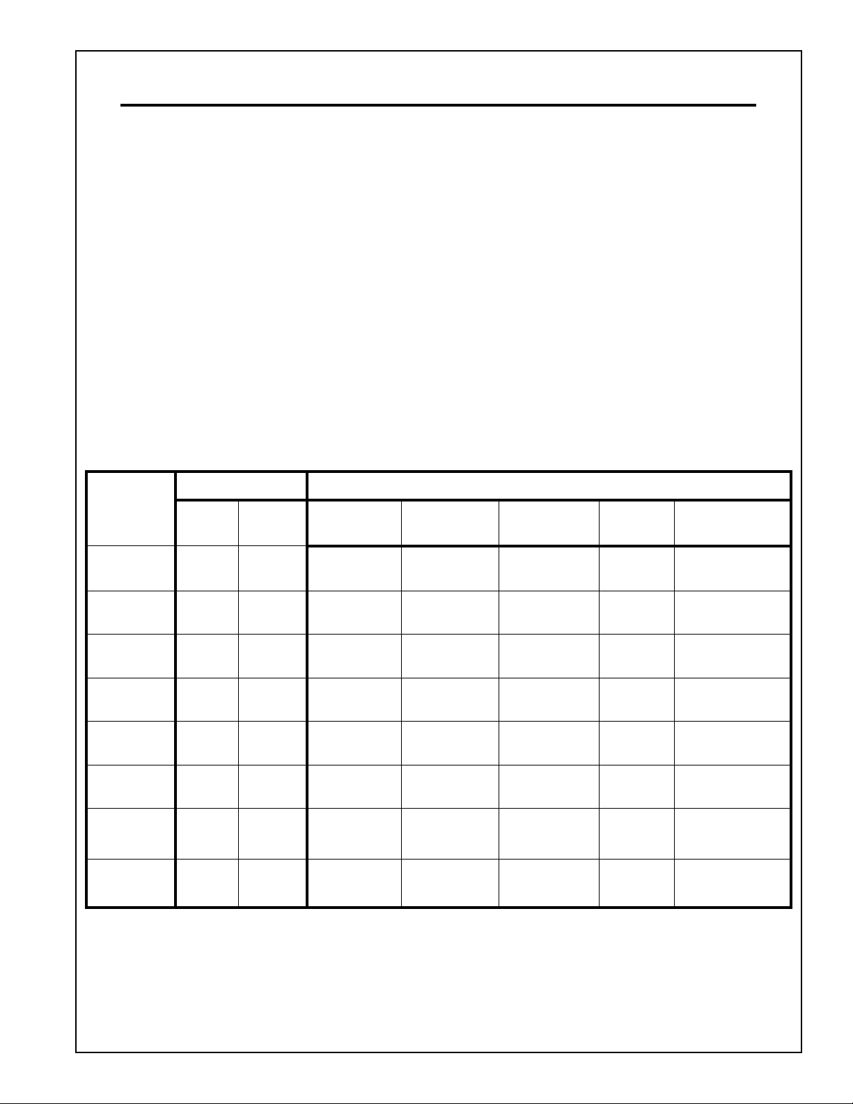
Selecting a Glentek Servo Motor to Replace a Stepper Motor
This section provides the specifications of various stepper motors so they can be compared to
equivalent servo motors. This should help in clearing up some of the confusion involved in choosing a
servo motor to replace a stepper.
Both Servo and Stepper motors have peak and continuous torque ratings. You will notice that the
peak and continuous torque ratings are generally the same with the stepper motor. Whereas, in a
servo motor, the peak torque rating is generally two or three times higher than the continuous torque
rating.
To select a servo motor, the peak torque must be equal to or greater than the peak torque rating of
the step motor. Since the horse power to weight ratio of a stepper motor is similar to that of a servo
motor, you should start out by selecting a servo motor approximately the same weight as the stepper
motor.
As a final system test, after selecting the Glentek servo motor replacement for your stepper motor,
Glentek strongly recommends you to install the servo motor and exercise your machine at maximum
axis duty cycle to make sure that the servo motor runs without over heating and the following error remains within desired specification.
Stepper Motor Glentek Servo Motor
Frame
Size
Torque
(in-oz)
Weight
(lbs)
Model
Number
Peak Torque
(in-oz)
Cont. Torque
(in-oz)
Weight
(lbs)
Overall
Length (inches)
NEMA 23 185 1.5
NEMA 23 495 3.1
NEMA 34 247 3.2
NEMA 34 465 3.7
NEMA 34 640 5.3
NEMA 34 1160 8.8
NEMA 42 1869 16.53
NEMA 42 2830 19.8
in-lb = in-oz x 0.0625 N-m = in-oz x 0.007
GMBN2310 216
GMBN2320 588
GMBN3405 297
GMBN3410 595
GMBN3420 850
GMBN3430 1188
GMBN4230 1274
GMBN4260 2547
72
@2.7 Amps
168
@4.7 Amps
99
@1.8 Amps
198
@3.4 Amps
298
@7.5 Amps
396
@6.0 Amps
424
@7.9 Amps
848
@15.8 Amps
2.3 4.59
3.8 6.12
4.2 4.20
5.7 5.26
9.0 6.89
12.0 7.88
15.0 6.42
21.0 8.78
Glentek Inc. 208 Standard Street, El Segundo, California 90245, U.S.A. (310) 322-3026 7

Application Guide
How to Choose the Correct Amplifier
Glentek produces a wide range of amplifiers. Some amplifiers have built in DC power supplies, referred
to as “Stand Alone”, while others are referred to as a module that requires customers to furnish DC
power supply. Glentek also offers 2 and 4 axis packages with power supply for multi-axis systems.
If the applications requires a NEMA 23, 34 or 42 motor, Glentek recommends using the SMB/SMC
9715 or SMB/SMC 9808 amplifiers. The SMB/SMC 9715 is a DC module amplifier primarily used for
multi axis systems. If it becomes necessary, the digital servo amplifiers can be configured to run either
brushless or brush type motors. However, Glentek does not recommend using a brush type motor if it
is possible. For more information on Glentek amplifiers, refer to installation and operation manual
(24AUG07) at the Glentek website.
The SMB amplifier has buss derived logic power, which means that you only need to provide buss
power to the amplifier to operate the digital logic board. However, in case of buss power removal or
failure, the digital logic board would not be able to keep track of the position of the motor shaft, and any
fault data would be lost. For this reason, the SMC amplifiers have an external “Keep Alive” logic power
source. This source can either be 5VDC, 24VDC or 110VAC depending on the model. Again, having
the “Keep Alive” power source allows the amplifier to keep track of all the digital data. Since the data is
not lost, the customers would not have to restart the machine at the “home” position i.e. if a machine
happened to lose buss power in the middle of a job once buss power was restored it would allow the
amplifier to continue and finish the job.
For detail model numbering, please refer to our installation and operation manual (24Aug07), pages
69-85.
Glentek Inc. 208 Standard Street, El Segundo, California 90245, U.S.A. (310) 322-3026 8

Sound Logic Breakout Board
The Sound Logic breakout board can be used with a Glentek motor and drive combination. The Sound
Logic board enables a customer to use their computer to send pulses to this board. This board then
sends these pulse and direction signals to the amplifier. The board connects directly to the parallel
printer port on a standard computer. In the future, the breakout board will be able to be controlled by
the standard USB port as well as the parallel printer port. The USB port will allow higher frequency
bandwidth pulse and direction signals to be ported out to the microstepping servo drives.
The board that was tested at Glentek is the Sound Logic PC-2-Route Rev. 1.9
For more information, please refer to Bob Campbell with Campbell Designs.
http://www.campbelldesigns.com/
Glentek Inc. 208 Standard Street, El Segundo, California 90245, U.S.A. (310) 322-3026 9

Application Guide
Artsoft Controls Software
Artsoft Controls software enables a computer to turn a manual milling machine into a computer controlled machine. This software was used in conjunction with the Sound Logic breakout board to effectively evaluate the needs of the CNC community. This software is complex for the novice user. However, Artsoft has many forums where help can be found and Artsoft also offers phone technical service.
Artsoft also has the ability to use their Mach software as a basis and create a program that is used
specifically for an application.
This software offers many command functions for the CNC machining process. The software is able to
control many characteristics for the pulses that are sent to the breakout board.
For more information refer to the Artsoft Controls website.
http://www.artsoftcontrols.com/
Glentek Inc. 208 Standard Street, El Segundo, California 90245, U.S.A. (310) 322-3026 10

Advantages of using Glentek Microstepping Servo Amplifiers
Glentek Omega series digital PWM servo amplifiers offer the latest in high performance DSP control of
both brushless and brush type motors. With extensive utilization of surface mount technology and special heat transfer techniques, the Omega series offers one of the world’s most powerful products for a
given form factor.
Following are some of key features of Glentek high performance servo amplifiers:
1. Digitally tuned - All parameters set digitally. No potentiometers to adjust. DSP control for the ultimate in system performance.
2. Silent operation - 24KHz PWM standard.
3. Smooth operation - The Glentek digital amplifier generates, using a Taylor expansion, a sinewave
output to the brushless servo motors, matching the back EMF waveform of the motor exactly. This
eliminates cogging and ripple torque and provides for extremely smooth operation.
4. Wide operating voltage - 20-370VDC for amplifier modules. 110-130VAC or 208-240VAC for Stand
Alone.
5. Direct AC operation - No transformer required for stand-alone unit or multi-axis chassis. The power
supply section includes DC power supply, cooling fan(s), soft-start circuitry and a regenerative voltage clamp with dumping (shunt) resistor
6. RS232 - high speed (115.2K baud) serial communication interface for set-up and tuning.
7. Software configurable - Glentek’s Windows™ based MotionMaestro™ software provides ease of
set-up and tuning with no previous programming experience required.
8. Dedicated digital inputs - Fault, +/- limits, motor over temperature and reset.
9. Fault protection - Amplifier RMS over current, amplifier under/over voltage, amplifier over temperature, motor over temperature and amplifier output short circuit. See installation and operation manual (24Aug07), page 24 (Faults).
10. Current Monitoring - View axis current while axis is moving at a fixed command rate. This is very
useful in machine maintenance. As an example, if something is binding the axis, the running current will go up. This torque monitoring is not available in stepper systems. See installation and operation manual (24Aug07), page 23 (Setup Oscilloscope). Select trace attributes source for
“Current Measured”.
11. Low Speed settable electronic circuit breaker with foldback current settings. See installation and
operation manual (24Aug07), page 20 (Motor Safety).
Conclusion
In general summary, comparing a stepper motor system with a servo motor system utilizing a Glentek
high bandwidth digital servo amplifier in the microstepping mode is like comparing a Model “T” Ford
with a Porsche or Ferrari sports car in performance capabilities.
Glentek Inc. 208 Standard Street, El Segundo, California 90245, U.S.A. (310) 322-3026 11

Application Guide
Brushless versus Brush-type Comparison
There are two basic types of motor design that are used for high-performance motion control systems:
Brush-Type PM (permanent magnet), and Brushless-Type PM. As you can see in the figure, a brushtype motor has windings on the rotor (shaft) and magnets in the stator (frame). In a brushless-type motor, the magnets are on the rotor and the windings are in the stator.
To produce optimal torque in a motor, it is necessary to direct the flow of current to the appropriate
windings with respect to the magnetic fields of the permanent magnets. In a Brush-Type motor, this is
accomplished by using a commutator and brushes. The brushes, which are mounted in the stator, are
connected to the motor wires, and the commutator contacts, which are mounted on the rotor, are connected to the windings. As the rotor turns, the brushes switch the current flow to the windings which
are optimally oriented with respect to the magnetic field, which in turn produces maximum torque.
In a brushless motor there is no commutator to direct the current flow through the windings. Instead,
an encoder, hall sensors or a resolver on the motor shaft senses the rotor position ( and thus the magnet orientation). The position data is fed to the amplifier which in turn commutates the motor electronically by directing the current through the appropriate windings to produce maximum torque. The effect
is analogous to a string of sequencing Christmas lights: the lights seem to chase each other around the
string. In this case, the magnets on rotor “chase” the magnetic fields of the windings as the fields
“move” around the stator.
The brushless motors are more reliable as Brush maintenance is eliminated and no brush dust is generated. The brushless motor can be driven to much higher RPM limits and typically have lower inertia.
The brushless motor also dissipates heat more efficiently since the stator windings are thermally connected to the outside of the motor case. It is also safer for explosive atmospheres and quieter and less
electrical noise generated as there is no brush arcing in a brushless motor.
Glentek Inc. 208 Standard Street, El Segundo, California 90245, U.S.A. (310) 322-3026 12

Glentek Inc. 208 Standard Street, El Segundo, California 90245, U.S.A. (310) 322-3026 13

Omega Series Digital PWM Brushless Servo Amplifiers
• PWM (Pulse-Width-Modulated) Brushless servo amplifiers to 20KW
Analog Brush Type Servo Amplifiers
• Linear Brush type servo amplifiers to 2.6KW
• PWM (Pulse-Width-Modulated) Brush type servo amplifiers to 28KW
Analog Brushless Servo Amplifiers
• Linear Brushless servo amplifiers to 3.5KW
• PWM (Pulse-Width-Modulated) Brushless servo amplifiers to 51KW
Permanent Magnet DC Brush Type Servo Motors
• Continuous Torques to 335 in. lb.
• Peak Torques to 2100 in. lb.
Permanent Magnet DC Brushless Servo Motors
• Continuous Torques to 1100 in. lb.
• Peak Torques to 2200 in. lb.
208 Standard Street, El Segundo, California 90245, USA.
Telephone: (310) 322-3026; Fax: (310) 322-7709
www.glentek.com e-mail sales@glentek.com
Applications Guide
Revision Date:
03 Nov 2008
 Loading...