

User Menu
GW-8F2G
Ver 1.03
2015/2/25

Contents
1. Start to use...................................................................................................... 3
2. Web page of “System Information”................................................................. 4
3. Quick Install .................................................................................................... 5
4. System Configuration ...................................................................................... 7
5. PoE.................................................................................................................. 8
6. LED Power Saving.......................................................................................... 11
7. Fundamentals ............................................................................................... 12
8. Security ......................................................................................................... 18
9. Statistics........................................................................................................ 19
10. Product Specification .................................................................................. 20
10.1. External Interfaces .............................................................................. 20
10.2. Port Functions ..................................................................................... 20
10.3. PoE Functions...................................................................................... 20
10.4. Push Button......................................................................................... 21
10.5. Power Supply –External Adaptor ......................................................... 21
10.6. System Information............................................................................. 21
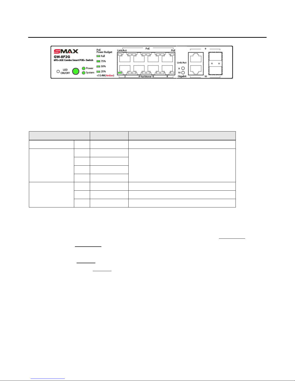
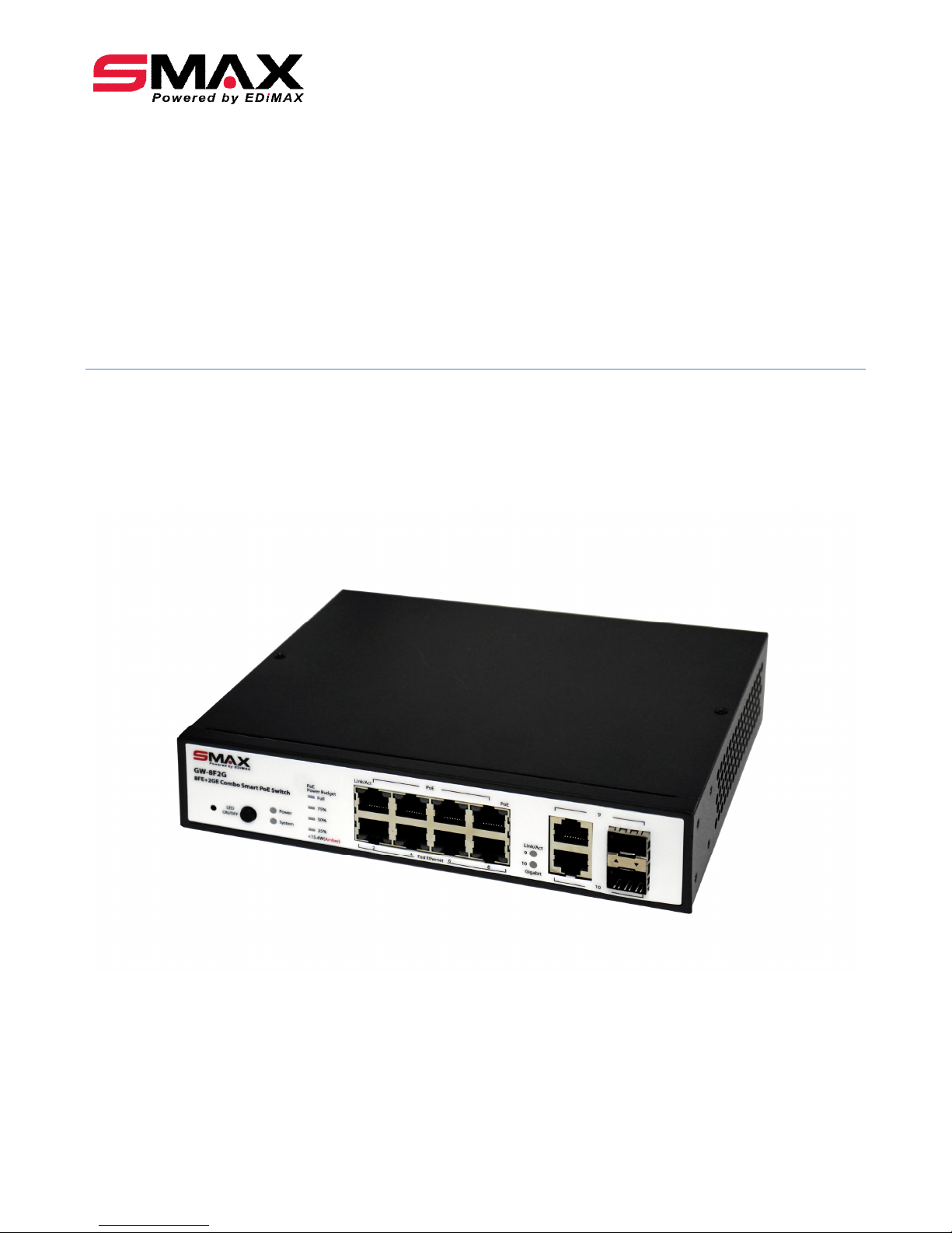
1. START TO USE
Fig. Front panel of GW-8F2G
Power on the Switch:
Power on the Switch before plug in any Ethernet cable, system will go through Power-On-Self-Test
(POST) with LEDs lighting in Green or Amber. Then, after completing the POST, LEDs will stay at the
state as the table below..
LED Indication Color / State Description
Power Green On The device is powered on.
Full Green On
75% Green On
50% Green On
PoE Power Budget
25% Green On
Power for POE is full, not been consumed yet.
dark During device boot-up.
Amber On Device passed POST and ready for operation.
System
Green On Successfully log into the device.
Log into the Switch:
Connect PC to any port of the Switch via Ethernet cable. Make sure the LAN setting of PC
is set to work in the same subnet as Switch device which the default IP address is 192.168.1.2
Type IP address 192.168.1.2 in the WEB Browser of PC, you will then be asked to enter ID and
Password so that you can log into the Switch device.
The default ID is “admin”.
The default Password is “admin”.
Press “OK”, you will log in and see the welcome page for “System Information”.
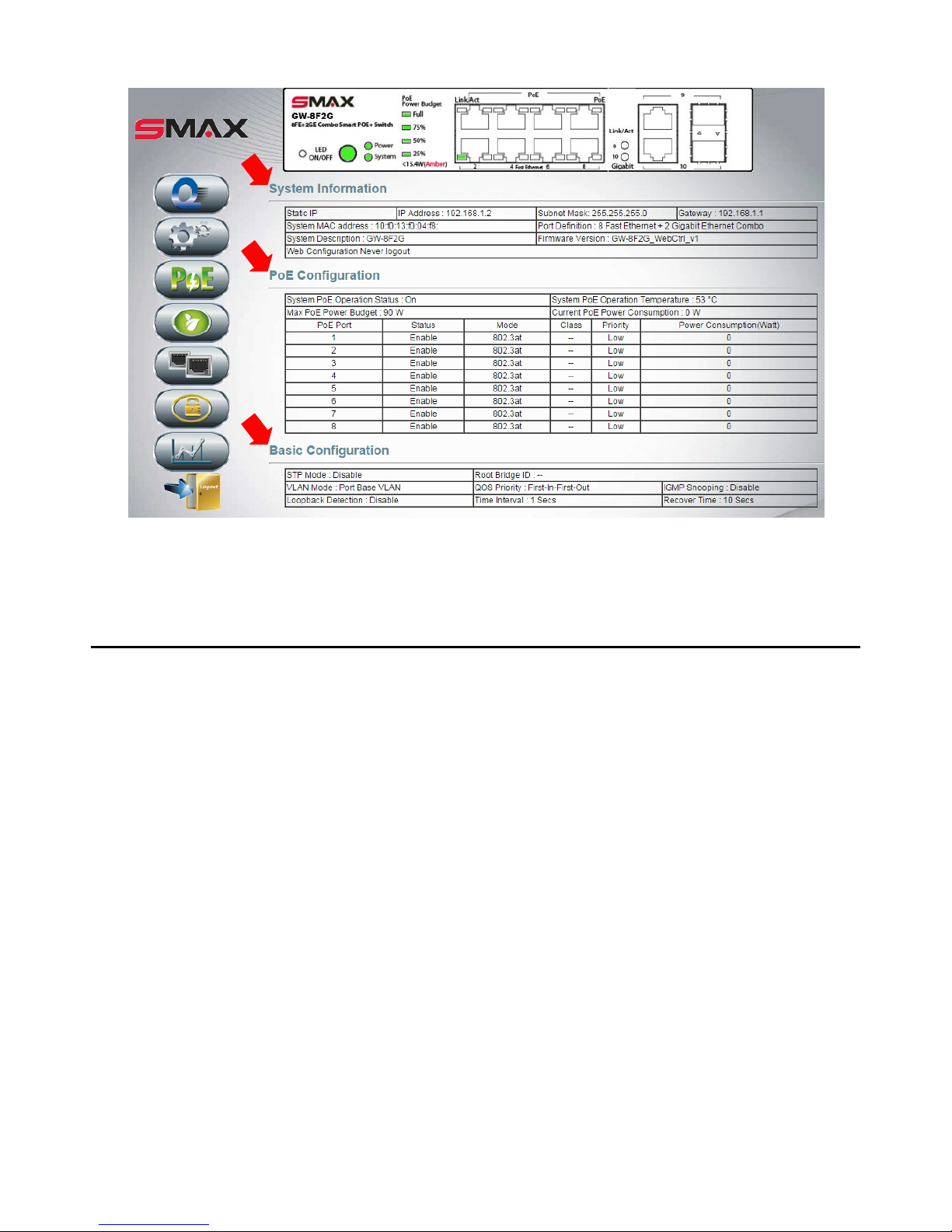
2. WEB PAGE OF “SYSTEM INFORMATION”
“System Information”, “POE Configuration” and “Basic Configuration” expose most of the important
information which Installer or Network Administrator may need for realizing the status and
configuration in a quick glance.
No setting function is provided on this page.
Want to configure the Switch device? Kick an icon on the left side of the page.
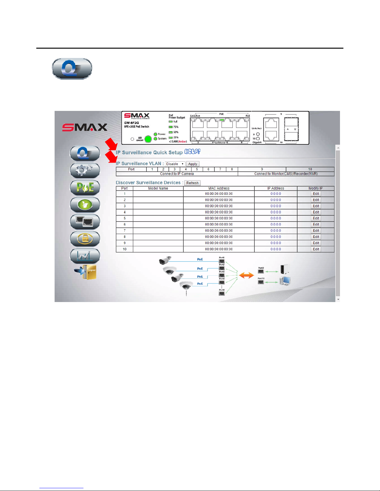
3. QUICK INSTALL
Quick Install
Fig. IP Surveillance Quick Setup
IP Surveillance Quick Setup requires only 2 steps to complete your surveillance network installation.
Step 1: Connect IPCAM, NVR, and PC as the Figure.
Step 2: Enable and Apply “IP Surveillance VLAN”. (Default value is Disable.)
Then, all connected devices will be discovered automatically; the discovered IPCAMs and NVR will be
securely bound to the Switch port. Press Refresh to get the table updated with connected devices’
MAC address and IP address. For network management purpose, user can modify IP address by Edit.
Now, we are done. Go check your monitor for the image captured.
Disable IP Surveillance VLAN, user probably prefer the other type of VLAN setting, Port Base or Tag
Base. Configure them on the page “Fundamentals” “VLAN” “VLAN Mode”.

Quick Install
What is IP Surveillance VLAN?
Enable IP Surveillance VLAN, the Switch will automatically find and setup the connected surveillance
devices, such as IP Camera or NVR which supports our proprietary “IP Finder Protocol”.
After discovered IP Camera, its IP address will be modified to ensure all IPCAMs and Switch are in the same
working subnet. Furthermore, security mechanism will bind the Ethernet port to the IPCAM’s MAC address.
“MAC + Port Binding” prevents IPCAM device from malicious replacement. Its result can be observed in
“Security” ”Binding Table”.
Furthermore, IP Surveillance VLAN makes the port 1~port 8 video stream be individually carried to and only
to the uplink port (destination port 9 or port 10). Source port (port 1~ port 8) is not allowed to
communicate to each other. So that network snooping is prevented.
Don’t you worry about the VLAN. All VLAN related setup is automatically done by this smart Switch. Its
result can be observed in “Fundamentals” ”VLAN””IP Surveillance Base”.
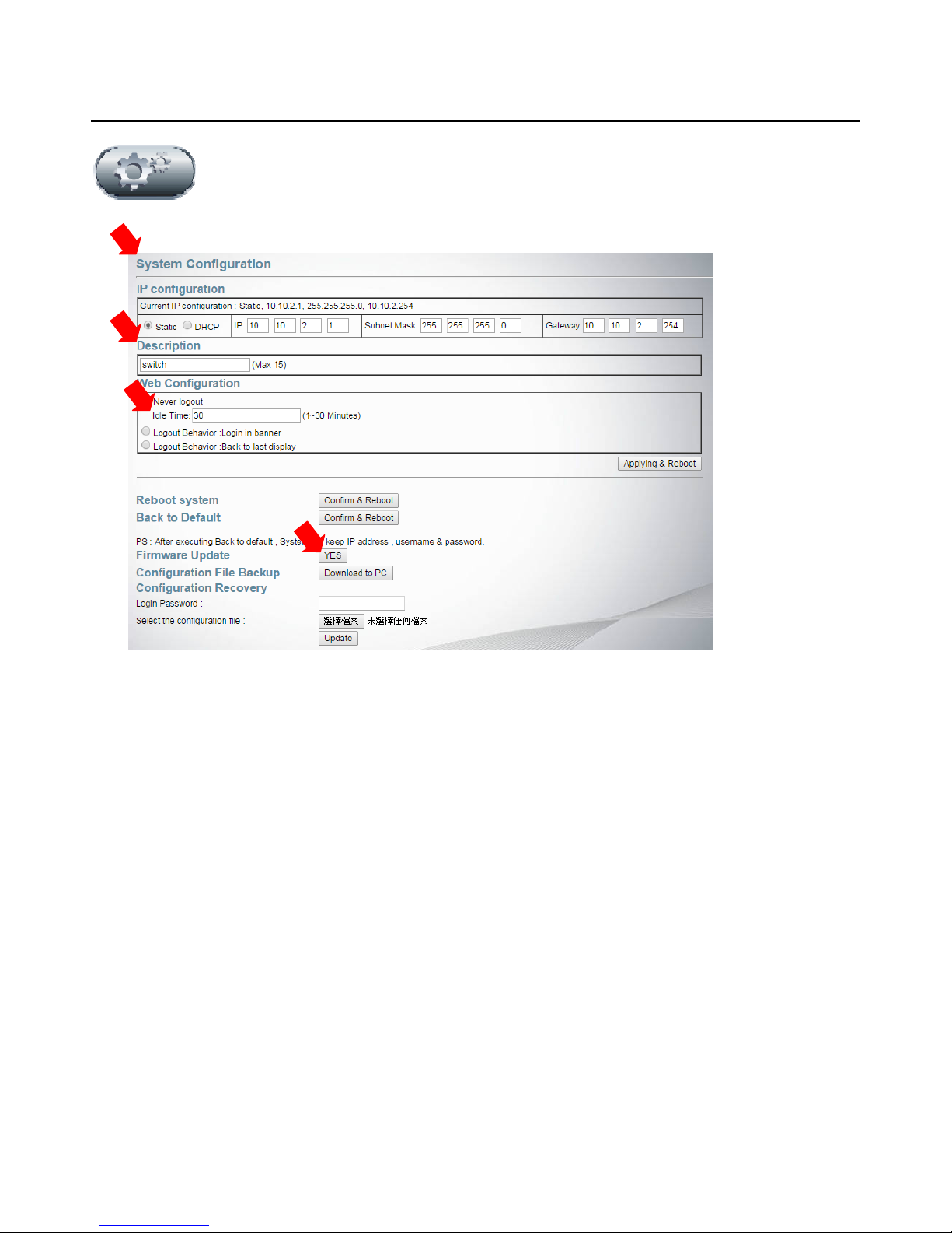
4. SYSTEM CONFIGURATION
System
In this page, user can re-set the IP address of this Switch device. Also you can give your Switch an
easily-remembered name in “System” “System Configuration” “Description”.
In “System” “System Configuration” “Web Configuration”, set “Idle Time” will make device
automatically log out by the time you set.
Click Yes on the “Firmware Update” will be requested to enter the password (default is “system”) and
to specify the location of new firmware (xxxxx.bin). Simply follow the instructions to update the
firmware which a few minutes are required for the process. During update, don’t turn off the power,
message “uploading” will keep showing on the web page.

5. POE
Power Over Ethernet
“Power Over Ethernet ” “POE Configuration” “System Level“ “System PoE Operation”
Disable and Apply will stop all POE activity of this Switch device.
Default of “System PoE Operation” is Enable (of course). This is a POE Switch, isn’t it?
“Power Over Ethernet ” “POE Configuration” “System Level“ “System Max PoE Power
Budget”
User can define the POE power budget of the Switch device here. Note that POE power budget of
GW-8F2G is 90 Watt, which is the Maximum power for POE usage.
“Power Over Ethernet ” “POE Configuration” “Port level” “Status”
If user want to disable Power Over Ethernet function of any specific port, set it here.
“Power Over Ethernet ” “POE Configuration” “Port level” “Priority”
- “Priority” setting (High, Middle, Low) decides the port’s priority of feeding power to PD.
This setting takes effect only upon the Switch device power-on.
- If there are several ports share the same priority, port number takes over the decision. The
smaller the port number is, the higher the priority is. For instance, port 1 and port2 share the
same priority “middle”, port1 priority will be higher than port2.

Default setting here applies the same priority to every port, meaning port1 priority is the highest
in this Switch device, followed by port2, then port3….

Power Over Ethernet
Enable “Power Over Ethernet ” “POE Power Delay” “ PoE Powering Timer Delay” “Delay”
and set “Powering delay time” will postpone the port to feed power to PD. At most, a port can delay
300 seconds before its powering. This setting takes effect only upon the Switch device power-on.

6. LED POWER SAVING
LED Power Saving
User can turn on or turn off LEDs of the front panel, except POWER LED. This green feature helps
energy saving.
If user sets “off”, meaning the LEDs of the front panel are turned off. However, in the WEB GUI, user
still can see the LED lighting reflecting the real network connection. (only appears on the graphic user
interface.)
Note there is a push button “LED ON/OFF” on the front panel which can perform the same function.

7. FUNDAMENTALS
Fundamentals - PORT
In general application, these parameters are automatically negotiated between Switch and
Client via IEEE802.3 standard.
Note that Disable “Fundamentals” “Port ” “Port Configuration” “Link” will only disable the
data path of that port. No impact on POE function. If user wants to disable POE function, go to “Power
Over Ethernet” “POE Configuration” “Port level” “Status”.

Fundamentals -QoS
“Fundamentals” “QoS” ”Priority Queue Configuration” ”First-In-First-Out”:
The first packet put into the queue will be firstly switched out.
“Fundamentals” “QoS” ”Priority Queue Configuration” “All-High-Before-Low”
After all packets in the high-priority queue are switched out, packet in the low-queue can be then
processed. No packet in the low-queue can be processed until high-queue is cleaned.
“Fundamentals” “QoS” ”Priority Queue Configuration” “Weight-Round-Robin”
Packet processing will be conducted in the manner like, for instance, process 8 packets of high queue,
then, process 8 packets in the low queue. And then, back to processing packets in the high queue….it’s
so called round-robin. User can set weight (processed packet counts) to high and low queues.

Fundamentals - QoS
“Fundamentals” “QoS” “CoS Setting (Port, 802.1p, IP TOS/DS)”
This Switch provides 2 priority queues, High and Low, for packet store-and-forward.
This Switch provides 3 types of Class of Service, Port based, 802.1p based, and IP TOS/DS Based.
Check the CoS of a Port will enable the Switch to follow the CoS setting and put the packet
into High or Low priority queue.
Select Port Base, packet of the specific Port will be put into High queue.
Select 802.1p, Switch will check 802.1p tag of the packet frame. If 802.1p tag is 4,5,6,7, the packet
will be put into High queue; tag is 0,1,2,3, the packet will be put into Low queue
Select IP TOS/DS, packet with ToS field lower than 001010 will be put into low queue.
If there are more than one CoS are selected at one port, Switch follows the IP TOS/DS setting first,
then 802.1p setting the second, and physical Port setting the last.

Fundamentals – Loop Free
“Fundamentals” “Loop Free” “Loop Detection” “Loop Detection Settings” “Time
Interval” set the time interval the Switch send out ARP for detecting loop.
( Enable “System Loop Detection” first.)
If user wants to enable “Auto Recover Function”, user can also set “Recover Time ” which is the
time interval before the blocked port is re-activated. (In case the port was in blocked state caused by
loop condition.)
Default value of “Auto Recover Function” is disable, meaning once a port is blocked by detected loop
condition, the port will stay in block mode. “Loop Status” shows whether the port is blocked or not.
To enable specific port’s loop detection function, user must enable “System Loop Detection” first.

Fundamentals – Loop Free
“Fundamentals” “Loop Free” “STP”
The Switch implements two versions of the Spanning Tree Protocol, the Rapid Spanning Tree Protocol
(RSTP) and STP.
“Hello Time” (1-10 sec) is the interval between two transmissions of BPDU packets sent by the Root
Bridge to tell all other switches that it is indeed the Root Bridge.
“Bridge Max Age” (6-40 sec) may be set to ensure that old information does not endlessly circulate
through redundant paths in the network, preventing the effective propagation of the new information.
“Forward Delay” (4-30 sec). Any port on the Switch spends this time in the listening state while
moving from the blocking state to the forwarding state.

Fundamentals - Trunking
“Fundamentals” “Trunking” “Link Aggregation Algorithm”
Traffic may be distributed over the member ports of the Trunking Group. The algorithm to distribute
traffic can be based on “MAC Source Address” or “MAC Source & Destination Address”.
“Fundamentals” “Trunking” “Member”
User can set totally 3 trunks. However, member of Trunk Group 1 must come from port 1 ~ port 4;
member of Trunk Group 2 must come from port 5 ~ port 8; member of Trunk Group 3 must come from
port 9 ~ port 10.
“Fundamentals” “Trunking” “Type”
Select “Static” or “LACP” protocol to create the truck group. LACP allows for the automatic detection
of links in a Port Trunking Group.
“Fundamentals” “Trunking” “Activity”
“Active” LACP port is capable of processing and sending LACP control frames. This allows LACP
compliant devices to negotiate the aggregated link so the group may be changed dynamically as needs
require. “Passive” LACP port cannot initially send LACP control frames.

8. SECURITY
Security
Change “Security” “Administrator” “Username” “Password” for logging into WEB GUI will take
effect only after “Apply & Reboot” the Switch.
For security concern, Enable “Security” “WEB Access Control” “State” and select “Allowed
Port” will limit the access right of Ethernet port. Only the port been selected can access the WEB GUI.
Default Disable means every port can access to WEB GUI after login check.
“Security” “MAC + Port Binding” allows user to bind specific port with up to 3 MAC addresses.
(Don’t forget Enable the “Security” “MAC + Port Binding” “Binding”)
Any link partner device with different MAC address from the one listed in the “Binding Table” will not
be allowed to enter into this Switch port. That also means the MAC Address Learning Function is not
effective on the port.

9. STATISTICS
Statistics – FDB Table
The “Statistics” “FDB Table” (Forwarding Database) table is to store the MAC addresses that have
been learned and which the ports that MAC address was learned on.
“Statistics” “Packet Counter” records 4 kinds of packet count. They are
- Transmit Packet and Receive Packet
- Collision counts and Transmit Packet
- Drop Packet and Receive Packet
- CRC error packet and Receive Packet

10. PRODUCT SPECIFICATION
10.1. External Interfaces
8 10/100-T ports + 2 10/100/1000-T ports
(1st ~ 8th FE ports support PoE, 9th ~ 10th GE port does not support PoE.)
Per port LED indicators.
System and POE LED indicators.
DC Inlet.
Push button. (can turn off/on Port LED display for energy saving.)
Factory Default button. (to reset system configuration to default value.)
10.2. Port Functions
Items Specifications
10/100 base-T LAN
Port 1-8 complies with :
1. IEEE 802.3
2. IEEE 802.3u
Support Half/Full-Duplex operation, Auto-negotiation, Auto MDI/MDIX
Support IEEE 802.3x Flow Control. (Full-Duplex mode)
10/100/1000 base-T LAN
Port 9-10 complies with :
1. IEEE 802.3
2. IEEE 802.3u
3. IEEE 802.3ab
Support Half/Full-Duplex operation, Auto-negotiation, Auto MDI/MDIX
Support IEEE 802.3x Flow Control. (Full-Duplex mode)IEEE 802.3x,
Flow Control support for Full-Duplex mode
SFP Ports
Port 9-10, complies with IEEE 802.3z.
2 x SFP , Physical bus shares with Giga port).
10.3. PoE Functions
Item Specifications
PoE Standard IEEE 802.3af/at
PoE Capable Ports Port 1~8
PoE Power Budget Total 90W Per Device.

PoE output power capacity Maximum output: 30Watt per port.
1. Support PoE and PoE+. (IEEE 802.3af /at standard.)
2. Automatically discover the connection of PD device.
3. Automatically disable port if the port current is over 720mA.
4. Via Web setting, working mode of each port can be configured.
5. When port is in the Auto mode, output port power limit will be associated
with PD Classification Value.
6. Priority of POE port is configurable. (Default setting is lower port No.
higher priority.)
7. Follow the standard PSE pin-out standard of Alternative B.
8. The maximum power used by power devices is defined by the following
classification. When Port works in Auto Mode, the output port power limit
will be associated with PD Classification Value.
Class
Usage
Minimum Power
Levels Output at
the PSE
Maximum Power
Levels at the
Powered Device
0 Default
15.4W 0.44 to 12.95W
1 Optional
4.0W 0.44 to 3.84W
2 Optional
7.0W 3.84 to 6.49W
3 Optional
15.4W 6.49 to 12.95W
4 Optional
30W 12.95W to 25.5W
10.4. Push Button
Function Location Description
Factory Default
Inner Push Button,
Front Panel
Pin the inner button 3 seconds then release, will reset system
configuration back to factory default.
LED ON/OFF Push Button,
Front Panel
Push once will turn off all functioning LEDs except Power
LED. Push again, turn on all functioning LEDs.
10.5. Power Supply –External Adaptor
Items Specifications
Total Electrical Power 120W
AC Input Voltage 100V ~ 240V, 50/60Hz
DC Output +54V: 2.22A (Max)
10.6. System Information
Items Specifications
Power Consumption 14.2W
MTBF 7 years or more
FAN Fanless
 Loading...