

SMAX GP1 User Manual

www.smax.com.tw
Ver 1.2
GP1 2MP Pan-Tilt Camera, PoE
User
Manual

www.smax.com.tw
CONTENTS
Chapter I.
Overview
Chapter 2.
Installation
Chapter 3.
Accessing
1.1. Read Before Use 1
1.2. Physical Description 2
1.3. Safety Instructions 4
1.4. Package Contents 5
1.5. Electromagnetic Compatibility 6
2.1. Hardware Installation 7
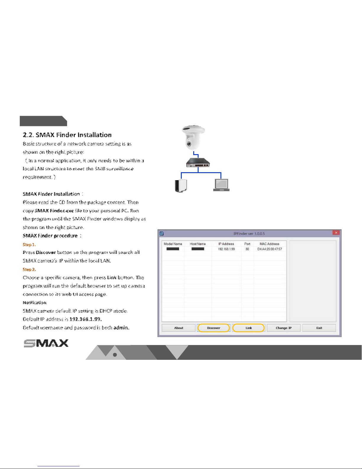
2.2. SMAX Finder Installation 8
2.3. Ready to Use 9
3.1. Network Deployment 10
3.2. Using Web Browsers 14
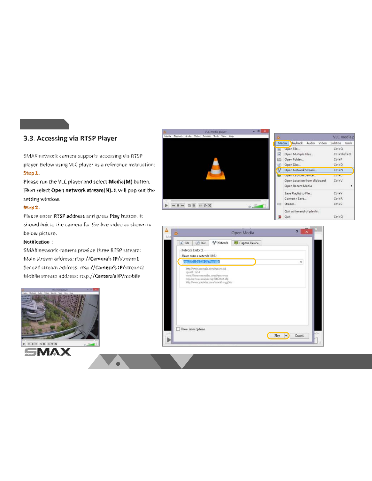
3.3. Using RTSP Players 15
Chapter 4.
WEB UI
Chapter 5.
Configuration
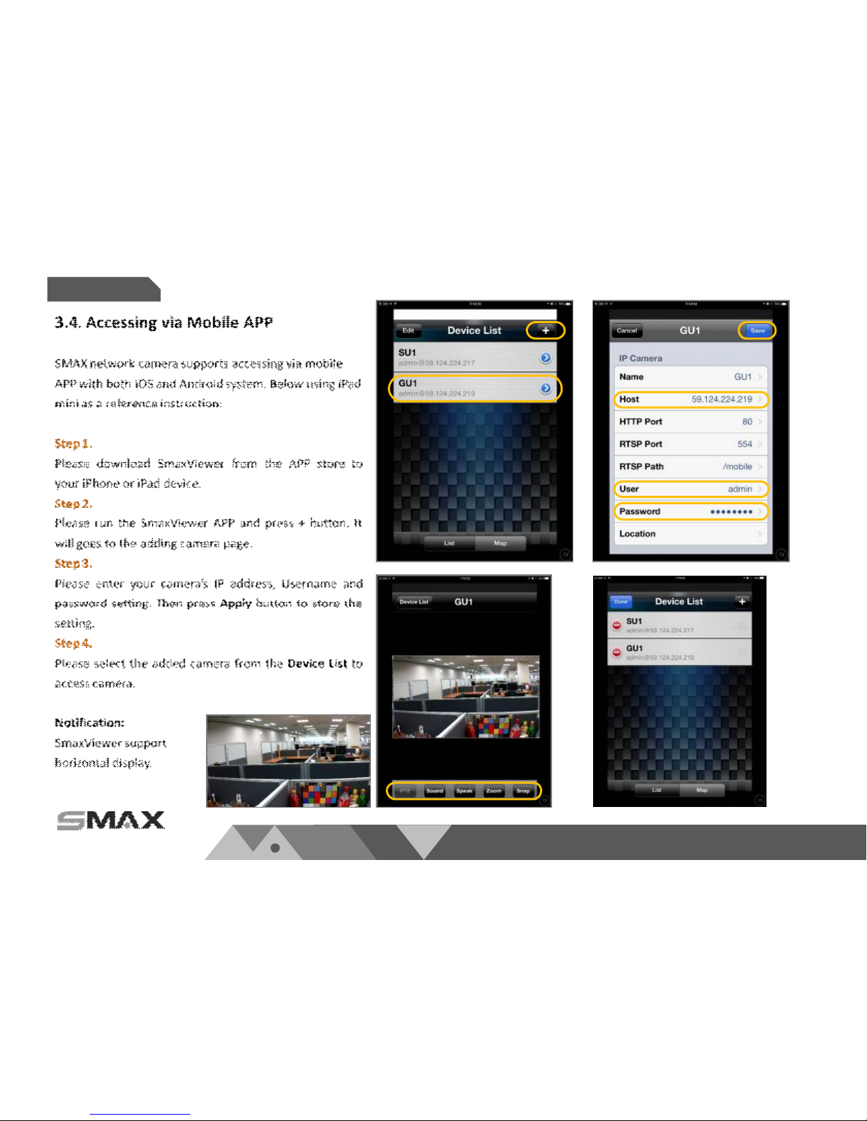
3.4. Using Mobile APP 16
3.5. Using VMS 17
4.1. Main Page 22
4.2. Client Settings 23
5.1. System Setup 24
5.2. Network Setup 28
5.3. Video & Audio Setup 38
5.4. SD Card Setup 51
5.5. Event Setup 55
5.6. Maintenance 61
5.7. Device info 64

www.smax.com.tw
CONTENTS
Chapter 6.
Appendix
6.1. URL Commands 66
6.2. Technical Specifications 81
6.3. Onvif Supports List 83
6.4. Liability 94
6.5. Copyright 95
P 01
www.smax.com.tw
Overview
Chapter I.
1.1. Read Before Use
This network camera is a professional
equipment for surveillance purpose. Please
comply with each national laws to prevent
from any relevant privacy violations before use.
In order to operate this network camera, it
require a basic knowledge of network
structure. For further use of project
application, it requests an advance level of
knowledge in lens optics selection, network
structure design, storage planning and
software capability.
This product service may be different since the
diversity of distributors. We suggest to
purchase SMAX product from S MAX direct
distributors or system integrators to get the
most complete after service.
Please first check the pa ckage contents are
complete with nothing missing. Then, carefully
read through all attentions and instructions
before use.
P 02
www.smax.com.tw
Overview
Chapter I.
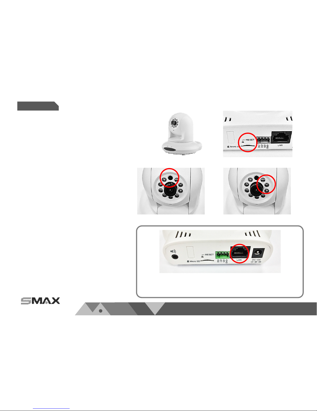
Light Sensor
IR LED
MicroSD/SDHC Card Slot
DIDO
Terminal
Block
DC 12V
Ethernet 10/100
RJ45 port
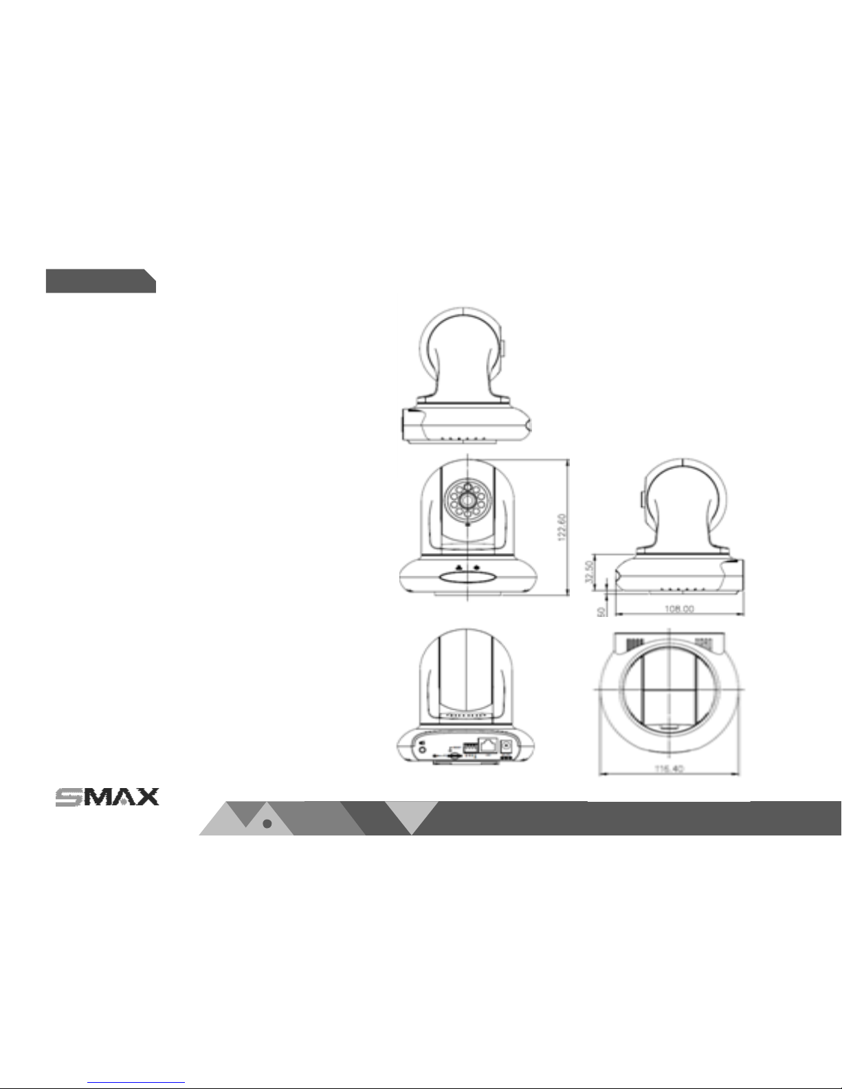
1.2. Physical Description
1.2.1. Mechanical and hardware interface
GP1 is built in with fixed l ens network camera. It can
be placed i ndoor environment where there is pan-tilt
function needed.
GP1 accepts both POE or DC 12V as power s upply.
Please noted that the DC 12V adapter is an extra
accessory which does not include in this package.
GP1 supports two ways audio function which can
connect with an external speaker and microphone.
GP1 has micro SD/SDHC card sl ot built in for recording
storage function.
P 03
www.smax.com.tw
Overview
Chapter I.
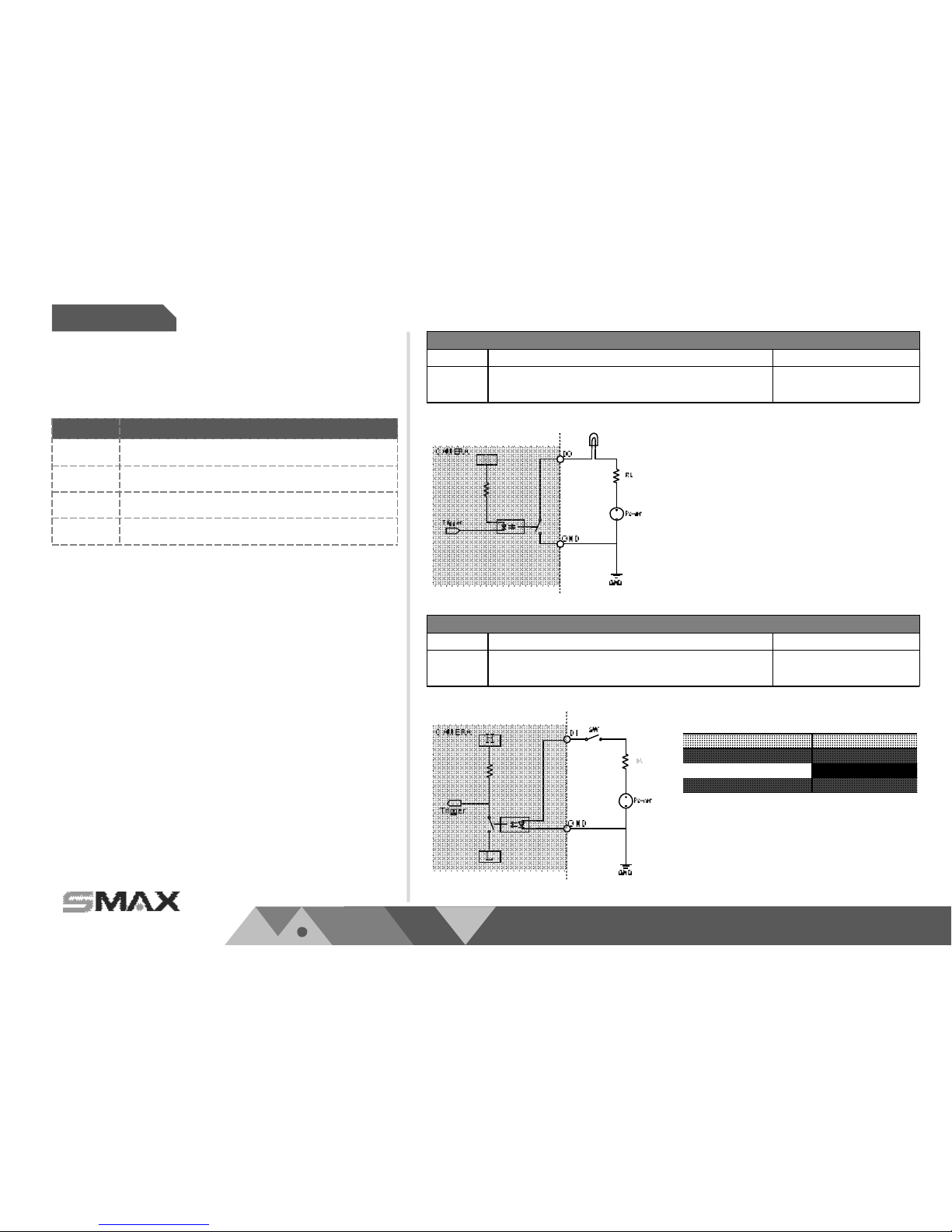
Digital Input
Pin Notes Specifications
Trigger is “Off”, DO connect to GND
Trigger is “On”, DO is floating
Max load:
30mA,30VDC
Digital Output
Pin Notes Specifications
DI is floating, trigger is “high”
DI is high, trigger is “low”
Max current input:
30mA
Suggested Component Value:
Power(VDC) RL(Ω)
3.3V 100 Ω
5V 200Ω
12V 510 Ω
Item Description
1
DI 2
2
DI 1
3
DO
4
GND
1.2. Physical Description
1.2.2. Digital Input (DI) & Digital Output (D0)

P 04
www.smax.com.tw
Overview
Chapter I.
1.3. Safety Instructions
Please carefully read through below safety instruction to prevent any damage of camera and person or any
reason that will cause the invalid of the warranty.
Network camera is a highly delicate electronic equipment. Please do not stumble or falling from high. It will
cause damage to the camera.
Please do not store the camera in a environment that the temperature or humidity are exceed camera’s
specification. Please also prevent from the direct expose of the sun light.
Network camera is not a toy. Please prevent from the use of the child for any accident possibility.
Please be careful when operate this network camera to prevent from any possibility that cause the device
or components to invade your body.
Please do not disassemble the camera to prevent from any abnormal function or operation.
When place the camera in a high humidity or wet environment, please select the IP66/67 level products.
Or else, please pus the camera in a outer housing box to prevent from damage.
Please do not put any wire or cable within the camera device to prevent from damage.
Cause of heat is a normal situation when operate network camera, please prevent direct contact when the
camera is in use for a while.
Please do not attach DC/AC power directly to the camera’s DI/DO port.
Please check the correct direction when insert the SDHC card into camera device.
Please contact your sales channel or find a regional SMAX distributor for any warranty issues.
P 05
www.smax.com.tw
Overview
Chapter I.
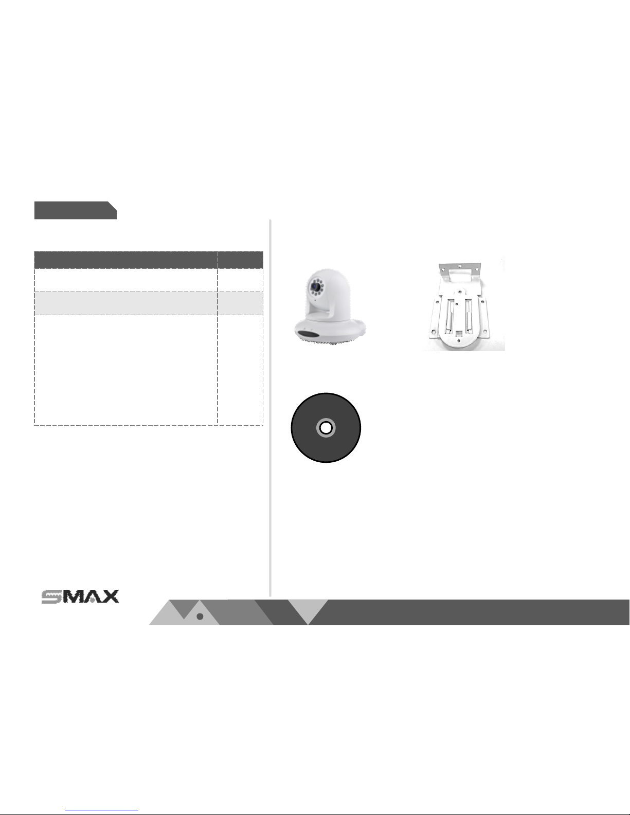
Description Qty
Network Camera 1
Tools package (Screw Kit…etc.) 1
CD:
A. Software:
SMAX VMS64 x 1
B. Doc:
Datasheet,
User Manual,
Quick Installation Guide
1
1.4. Package Contents
CD
Network Camera Bracket

P 06
www.smax.com.tw
Overview
Chapter I.
1.5. EMC(Electromagnetic Compatibility)
FCC Statement
This device compiles with FCC Rules Part 15. Operation is subject to the following two conditions.
(1.) This device may not cause harmful interference, and
(2.)This device must accept any interference received, including interference that may cause undesired
operation.
This equipment has been tested and found to comply with the limits for a Class A digital device,
pursuant to Part 15 of the FCC Rules. These limits are designed to provide reasonable protection
against harmful interference when the equipment is operated in a commercial environment. This
equipment generates, uses, and can radiate radio frequency energy and, if not installed and used in
accordance with the installation manual, may cause harmful interference to radio communications.
Operation of this equipment in a residential area is likely to cause harmful interference, in which case
the user will be required to correct the interference at his own expense.
CE Mark Warning
This is a Class A product. In a domestic environment, this product may cause radio interference, in
which case the user may be required to take adequate measures.
P 07
www.smax.com.tw
Installation
Chapter 2.
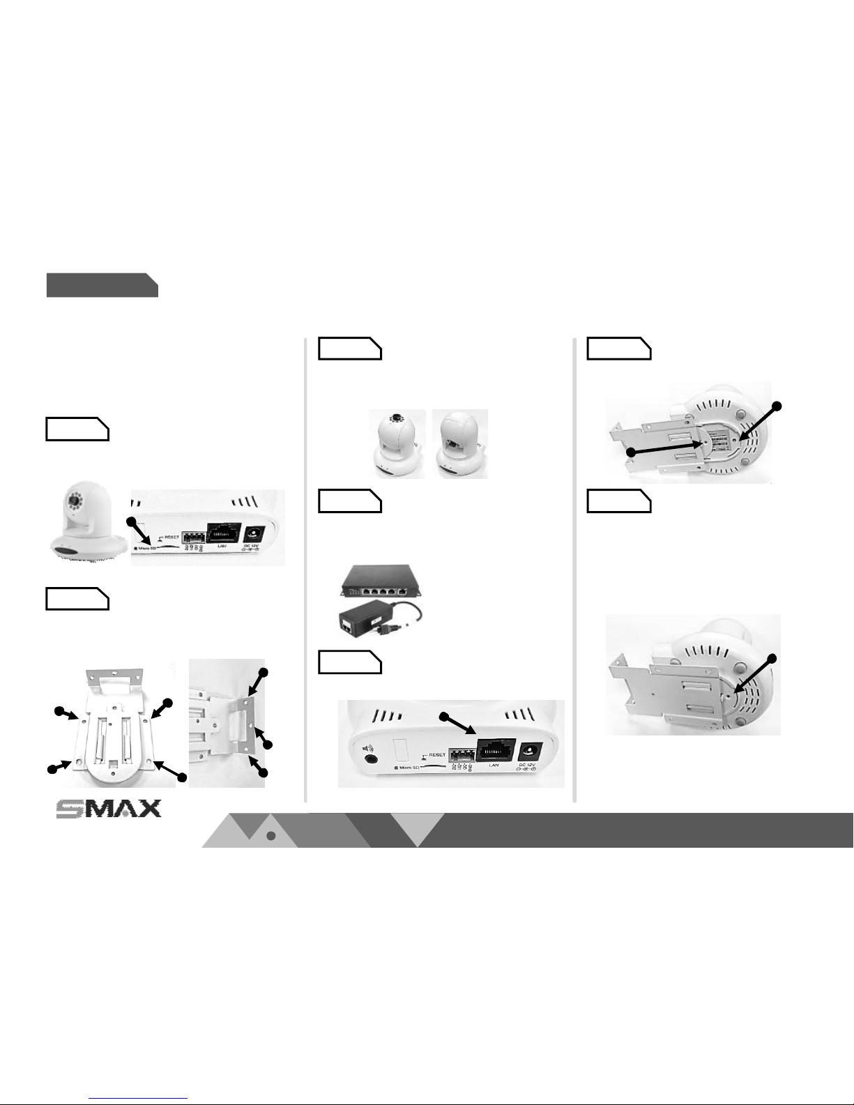
Setup 1.
Setup 2.
Inset micro SD card in the back of
the camera if necessary.
Setup 4.
Setup 5.
Setup 3.
DC 12V
*. The network camera
supports both PoE power
or DC 12V adapter
Please conne ct this network camera
to a *PoE switch, PoE injector, or DC
12V adapter. Ma ke sure all
connection is stable .
Please connect the network cable to
network Camera.
Setup 6.
Please slide the ca mera with the wall
mount bracket and tight it with
supplied screws.
Setup 7.
Please make sure all setup
procedures of this network camera
is comple te. Then process to the
next step of network a ccessing.
Please fix the wall mount bracket on
the wall or ceiling with s upplied
screws.
Please adjust viewing a ngle and
focus as your desire. Pan and tilt
function can be managed via
network connection.
2.1. Installation
Plea se follow below instructions to setup
your network camera.
P 08
www.smax.com.tw
Installation
Chapter 2.
VR1
or NVR / VMS
IP address: 192.168.1.88
Subnet Mask: 255.255.255.0
Gateway: 192.168.1.1
PC
IP address: 192.168.1.10
Subnet Mask: 255.255.255.0
Gateway: 192.168.1.1
Network Camera
IP address: 192.168.1.99
Subnet Mask: 255.255.255.0
Gateway: 192.168.1.1
4+2 ports
PoE Switch
P 09
www.smax.com.tw
Installation
Chapter 2.
P 10
www.smax.com.tw
Accessing
Chapter 3.
Internet
網際網路
VR1 PC
Network Camera
4+2 ports
PoE Switch
xDSL Modem
Router
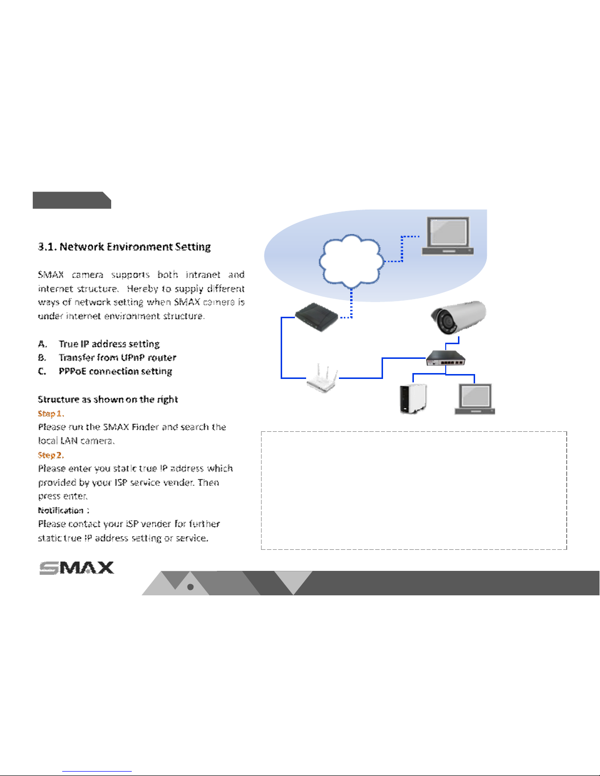
Internet and Intranet setting structure illustration
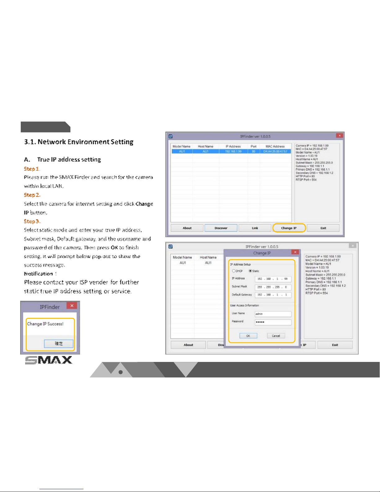
Notification:
When you have the true IP address, you may set your network camera in sta tic IP
mode. Then you may use the internet browser by entering this static true IP address
to access your network camera.
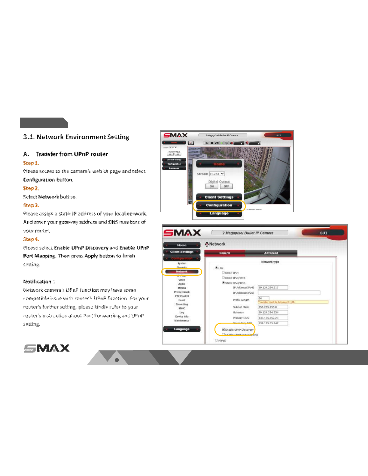
If your true IP address was set to yo ur router, you ma y use the port forwardin g
function and turn on the UPnP function within yo ur network camera to connect. This
is the solution that solves the problem when a SMB surveillance project has lack of
true IP address to manage. However, please noted that the performance of the
camera will be strongly depends on the performance o f the router. It ma y cause
abnormal connecting due to this issue. <Please refer to 3.1. B. setting >
P 11
www.smax.com.tw
Chapter 3.
Accessing
P 12
www.smax.com.tw
Chapter 3.
Accessing
P 13
www.smax.com.tw
Chapter 3.
Accessing
P 14
www.smax.com.tw
Accessing
Chapter 3.
SMAX Network Camera connection:
SMAX network ca mera supports multi ple connections
for accessing. Includes multiple browsers connecti on,
video player connecti on that supports RTSP,
SmaxViewer APP connection, or SMAX VMS or CMS
software to access. Each connection fulfill different
surveillance application for different purpose.
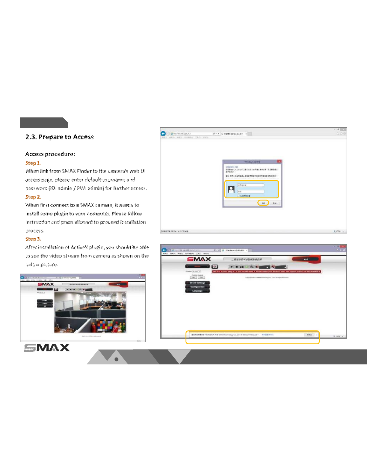
3.2. Accessing via Web UI
You can select browser for the purpose of monitoring,
system setting, SD card recording and searching, local
computer recording, audio function…etc.
Notification:
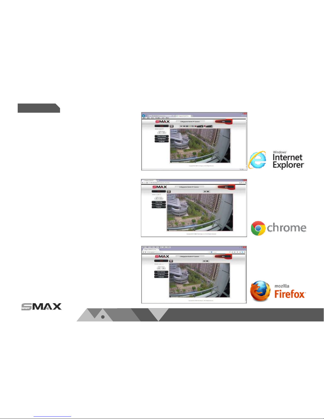
1)We suggest to use IE 9/10/11 and above version to
access SMAX network camera.
2)Other than IE browser, SMAX network ca mera als o
support both Google Chrome and Mozilla Firefox
browsers for accessing.
3)If using Google Chrome and Mozilla Fi refox to access,
those browsers will need Quick Time to play the live
video. I f your computer has not install Quick Time
software, please download and install it. Then refresh
the browser.
P 15
www.smax.com.tw
Accessing
Chapter 3.
www.smax.com.tw
Accessing
Chapter 3.
P 16
www.smax.com.tw
P 17
Accessing
Chapter 3.
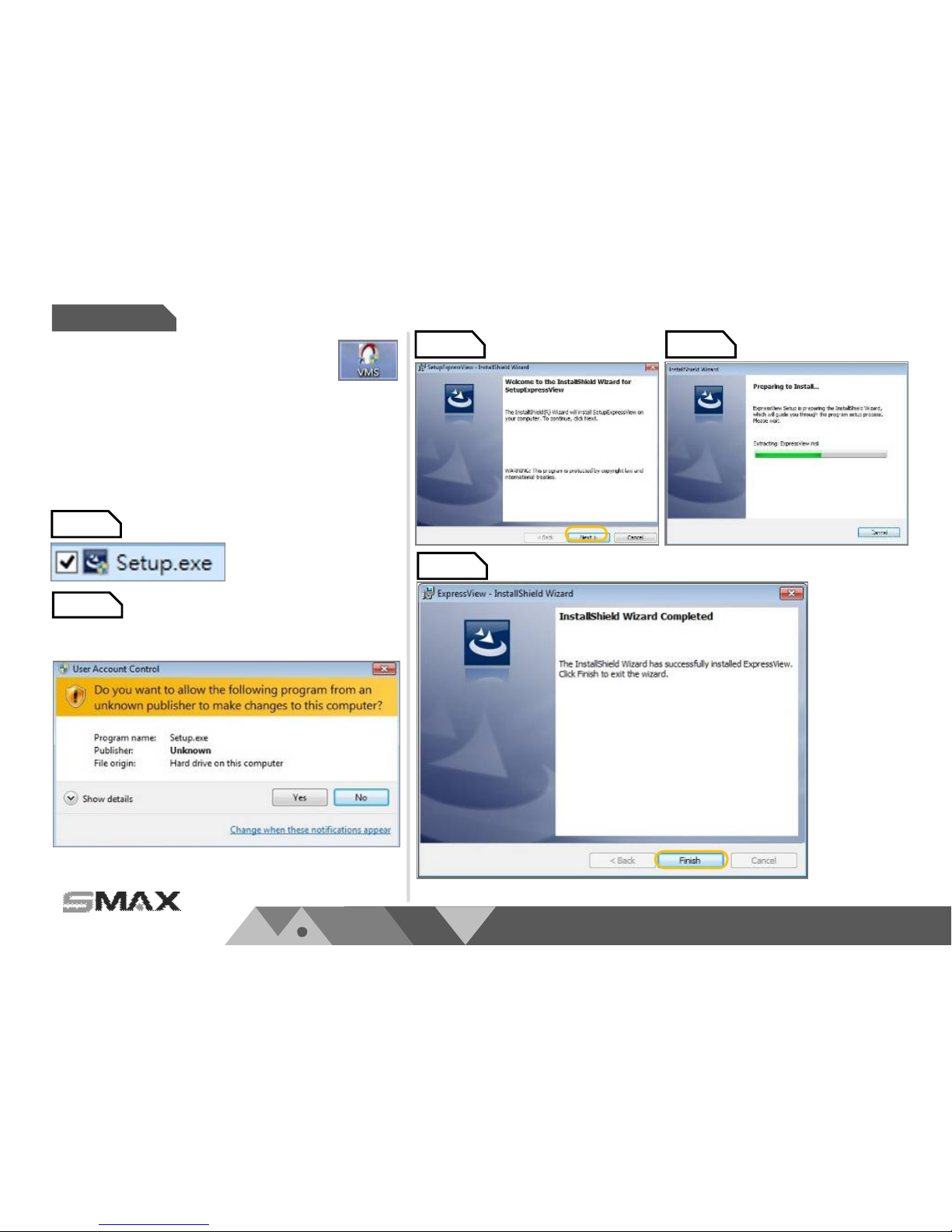
Setup 1.
Setup 2.
Setup 3. Setup 4.
Setup 5.
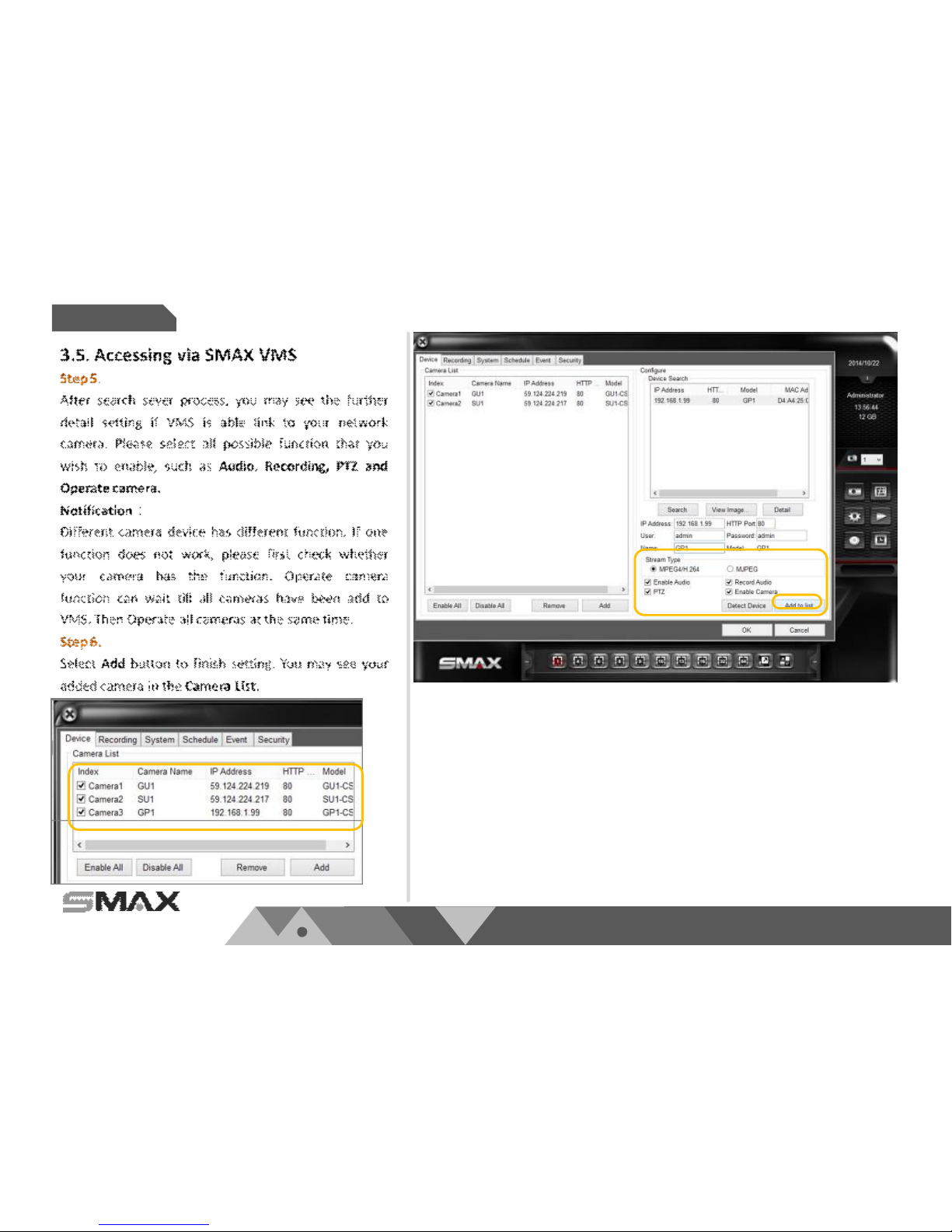
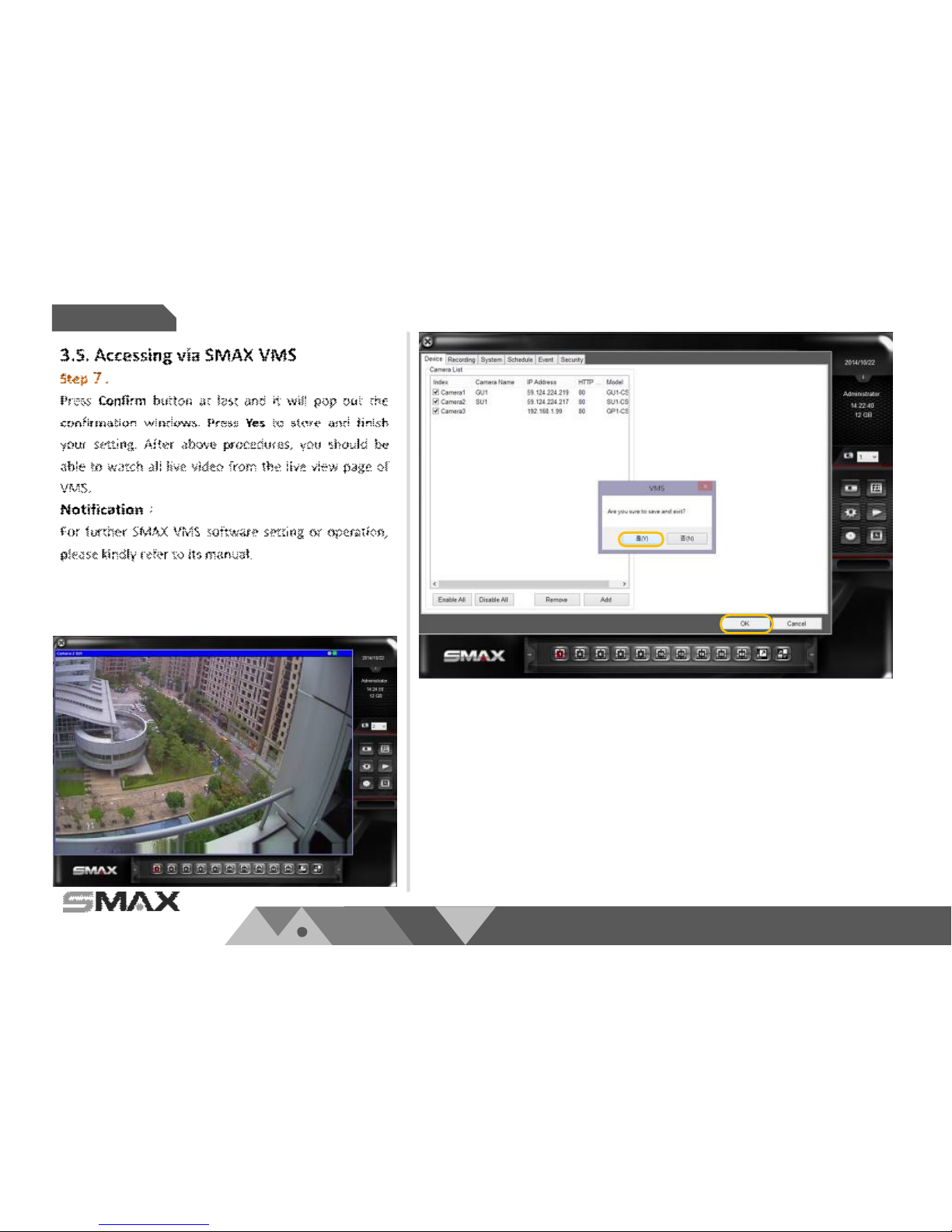
3.5. Accessing via SMAX VMS
Please select Setup.exe from the SMAX VMS
folder of CD content. Follow installation
procedure and setting. Then you can run the
SMAX VMS software to use.
3.5.1. SMAX VMS Installation procedure:

www.smax.com.tw
Accessing
Chapter 3.
P 18

www.smax.com.tw
Accessing
Chapter 3.
P 19
www.smax.com.tw
Accessing
Chapter 3.
P 20
www.smax.com.tw
Accessing
Chapter 3.
P 21
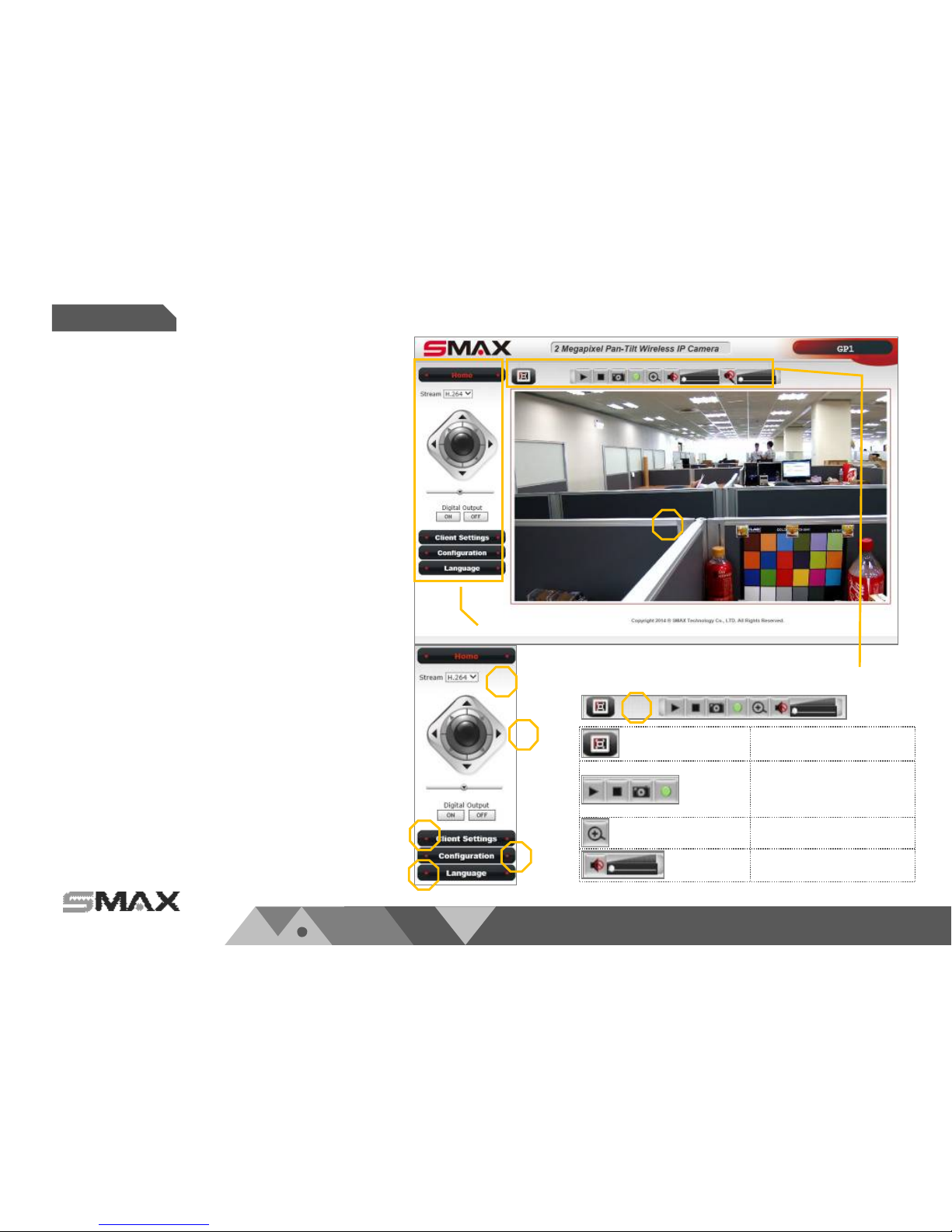
Original size displa y
Stream play/stop
Snapshot
Recording
Digital zoom
Two way audio opera tion
www.smax.com.tw
WEB UI
Chapter 4.
P 22
1
2
3
4
5
7
4.1. Home page
You can access SMAX network camera via web browser
to monitor li ve view, manage setting, SD card
recording…etc. There i s a complete i ntroduction
procedure of all function in the foll owing chapter four
and five.
Homepage function list:
1)Live view screen
2)Select stream format
3)Select language
4)Client settings
5)System configuration
6)PT Control
7)Live view operation control list
Notification:
Function list of icons as shown on the picture to the
right.
Main function List
Live view operation list
6
www.smax.com.tw
WEB UI
Chapter 4.
P 23
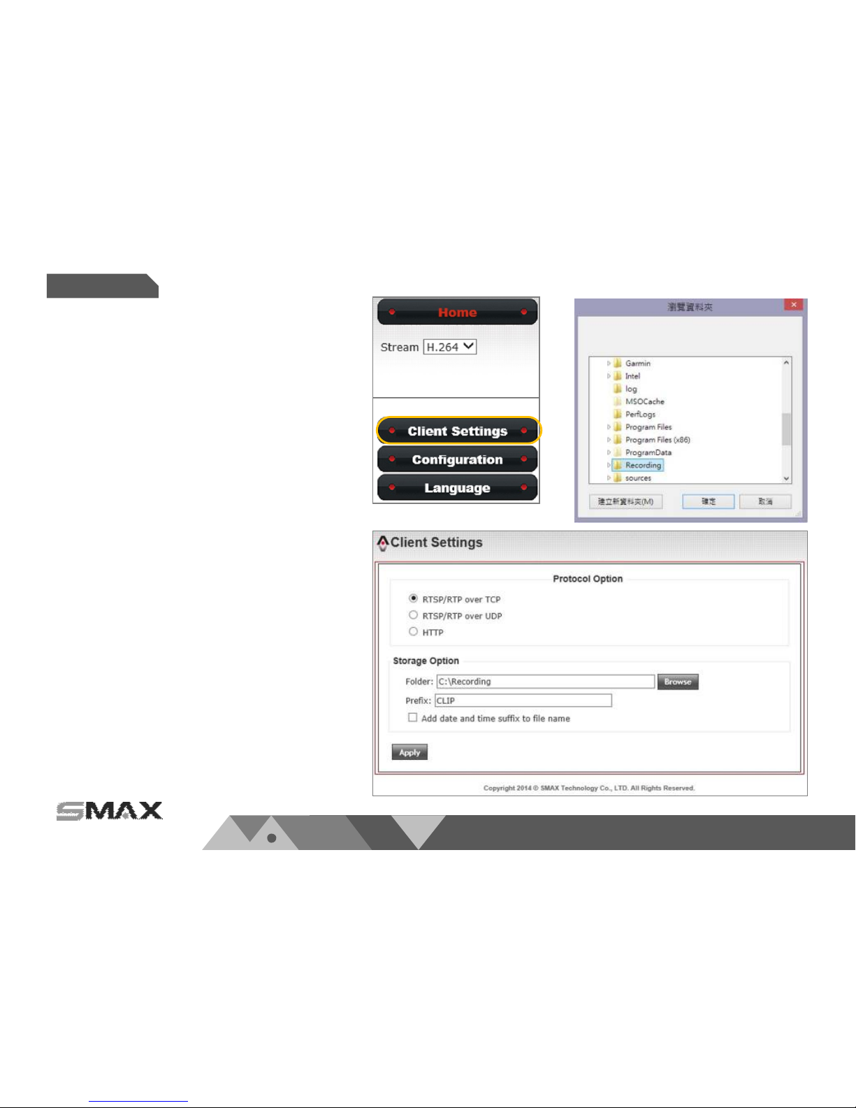
4.2. Client Settings
4.2.1. Protocol option
This setting is to define your protocol option.
Default set as RTSP/RTP over TCP. This protocol
make sure that all image data must be
transferred. But if you choose the image quality
comes first, then you can change to RTSP/RTP
over UDP. If your network environment only
allows to connect with web p age, then you can
change to HTTP protocol.
4.2.2. Storage Option
This setting is to define your storage option.
When doing a recording action, you can set
where the recording file saves to. Press Browse
button to set your folder path name. You can
also name the Prefix of recording file and select
to Add date and time suffix to file name. At last,
press Apply to complete setting.
www.smax.com.tw
Configuration
Chapter 5.
P 24
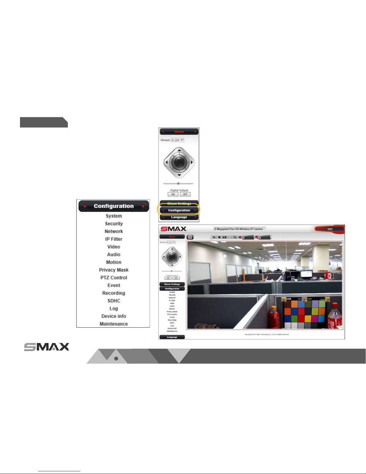
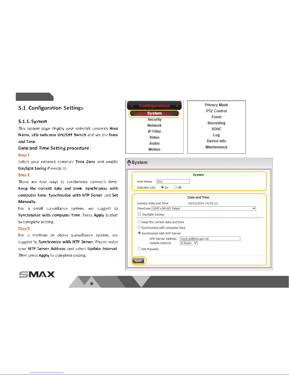
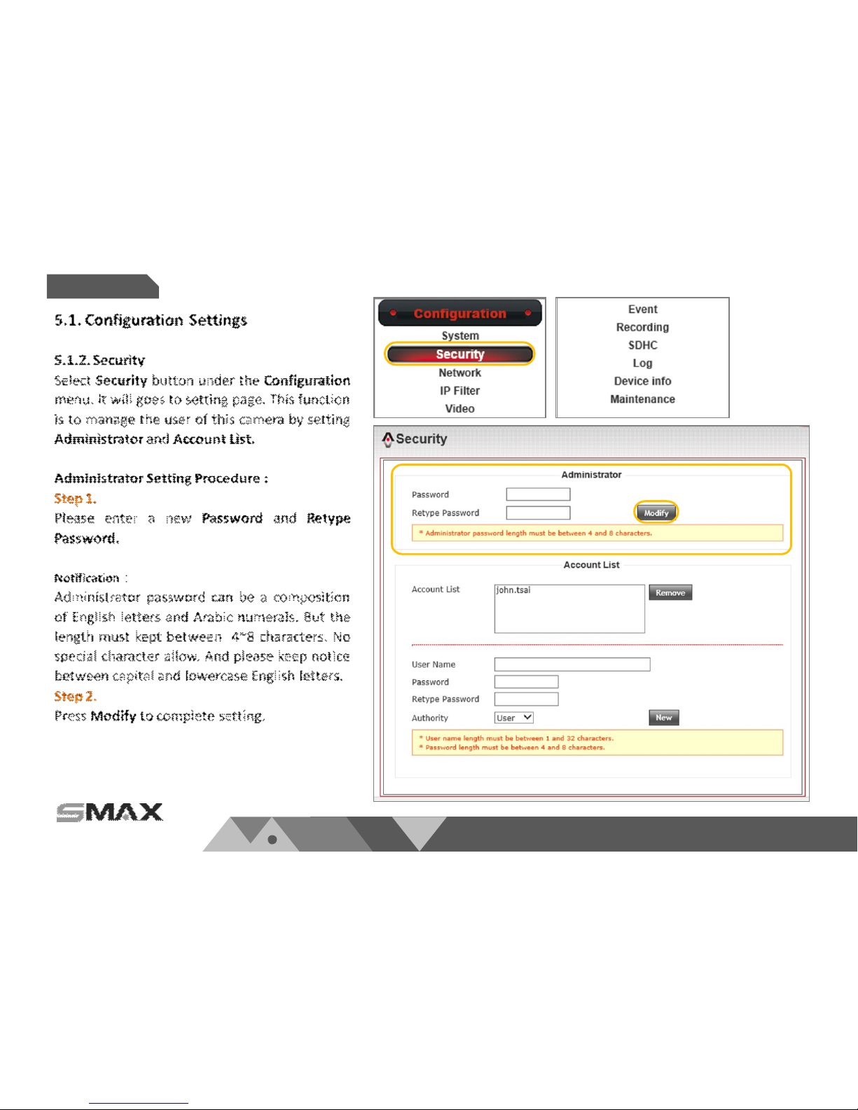
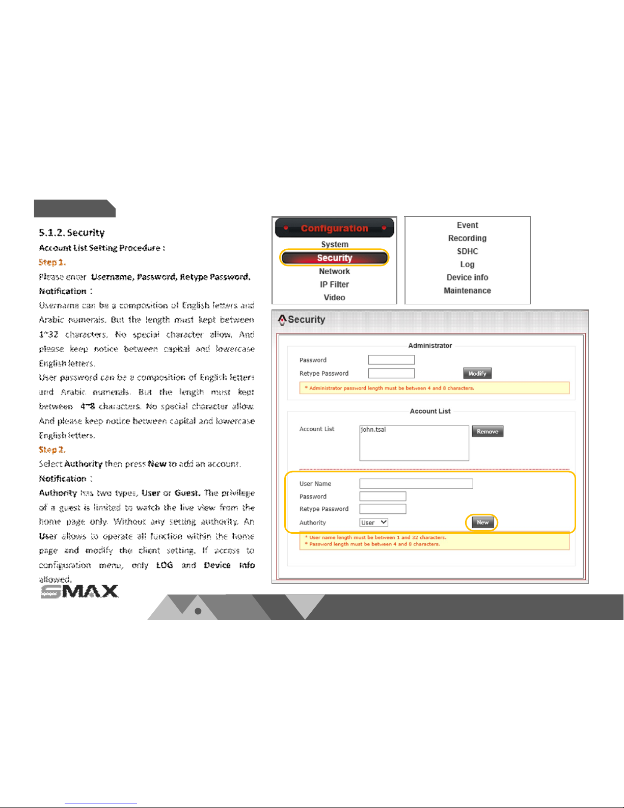
5.1. Configuration Settings
In the menu of confi guration, i t includes all operating
function for s ettings, maintenance, l og and device
informati on…etc.
Configuration menu as shown below:
1)System
2)Security
3)Network
4)IP Filter
5)Video
6)Audio
7)Motion Detection
8)Privacy Mask
9)PTZ Control
10)Event
11)Recording
12)SDHC
13)Log
14)Device Info
15)Maintenance
www.smax.com.tw
P 25
Configuration
Chapter 5.
www.smax.com.tw
P 26
Configuration
Chapter 5.
www.smax.com.tw
P 27
Configuration
Chapter 5.
 Loading...