

SMA Solar Technology AG SUNNY TRIPOWER 15000TL, SUNNY TRIPOWER 25000TL, SUNNY TRIPOWER 20000TL Operating Manual
Operating manual
SUNNY TRIPOWER 15000TL / 20000TL /
25000TL
STP15-25TL-30-BE-en-14 | Version 1.4ENGLISH

Legal Provisions
SMA Solar Technology AG
Legal Provisions
The information contained in these documents is the property of SMA Solar Technology AG. No
part of this document may be reproduced, stored in a retrieval system, or transmitted, in any form or
by any means, be it electronic, mechanical, photographic, magnetic or otherwise, without the prior
written permission of SMA Solar Technology AG. Internal reproduction used solely for the purpose
of product evaluation or other proper use is allowed and does not require prior approval.
SMA Solar Technology AG makes no representations or warranties, express or implied, with
respect to this documentation or any of the equipment and/or software it may describe, including
(with no limitation) any implied warranties of utility, merchantability, or fitness for any particular
purpose. All such representations or warranties are expressly disclaimed. Neither SMA Solar
Technology AG nor its distributors or dealers shall be liable for any indirect, incidental, or
consequential damages under any circumstances.
The exclusion of implied warranties may not apply in all cases under some statutes, and thus the
above exclusion may not apply.
Specifications are subject to change without notice. Every attempt has been made to make this
document complete, accurate and up-to-date. Readers are cautioned, however, that product
improvements and field usage experience may cause SMA Solar Technology AG to make changes
to these specifications without advance notice, or per contract provisions in those cases where a
supply agreement requires advance notice. SMA Solar Technology AG shall not be responsible for
any damages, including indirect, incidental or consequential damages, caused by reliance on the
material presented, including, but not limited to, omissions, typographical errors, arithmetical errors
or listing errors in the content material.
SMA Warranty
You can download the current warranty conditions from the Internet at www.SMA-Solar.com.
Trademarks
All trademarks are recognized, even if not explicitly identified as such. Missing designations do not
mean that a product or brand is not a registered trademark.
SMA Solar Technology AG
Sonnenallee 1
34266 Niestetal
Germany
Tel. +49 561 9522-0
Fax +49 561 9522-100
www.SMA.de
Email: info@SMA.de
Status: 7/22/2019
Copyright © 2019 SMA Solar Technology AG. All rights reserved.
Operating manualSTP15-25TL-30-BE-en-142

SMA Solar Technology AG
Table of Contents
Table of Contents
1 Information on this Document................................................. 5
1.1 Validity........................................................................................................................ 5
1.2 Target Group.............................................................................................................. 5
1.3 Content and Structure of this Document ................................................................... 5
1.4 Levels of Warning Messages.................................................................................... 5
1.5 Symbols in the Document .......................................................................................... 6
1.6 Typographies in the Document.................................................................................. 6
1.7 Designation in the document..................................................................................... 6
1.8 Additional Information............................................................................................... 7
2 Safety ........................................................................................ 8
2.1 Intended Use .............................................................................................................. 8
2.2 IMPORTANT SAFETY INSTRUCTIONS.................................................................... 8
3 Scope of Delivery ..................................................................... 13
4 Product Overview .................................................................... 14
4.1 Product Description.................................................................................................... 14
4.2 Symbols on the Product ............................................................................................. 15
4.3 Interfaces and Functions ............................................................................................ 16
4.4 LED Signals................................................................................................................. 18
5 Mounting................................................................................... 19
5.1 Requirements for Mounting ....................................................................................... 19
5.2 Mounting the Inverter................................................................................................. 21
6 Electrical Connection ................................................................ 24
6.1 Overview of the Connection Area............................................................................ 24
6.1.1 View from Below..................................................................................... 24
6.1.2 Interior View............................................................................................ 25
6.2 AC Connection........................................................................................................... 26
6.2.1 Requirements for the AC Connection.................................................... 26
6.2.2 Connecting the Inverter to the Utility Grid ............................................ 27
6.2.3 Connecting Additional Grounding........................................................ 29
6.3 DC Connection........................................................................................................... 30
6.3.1 Requirements for the DC Connection.................................................... 30
6.3.2 Connecting the PV Array........................................................................ 30
6.4 Retrofitting the Surge Arrester Type II ....................................................................... 32
7 Commissioning ......................................................................... 33
Operating manual STP15-25TL-30-BE-en-14 3

Table of Contents
7.1 Commissioning Procedure ......................................................................................... 33
7.2 Configuring the Country Data Set............................................................................. 33
7.3 Commissioning the Inverter........................................................................................ 40
SMA Solar Technology AG
8 Configuration............................................................................ 43
8.1 Configuration Procedure............................................................................................ 43
8.2 Integrating the Inverter into the Network.................................................................. 43
8.3 Changing Operating Parameters.............................................................................. 44
8.4 Configuring the Modbus Function............................................................................. 44
8.5 Configuring Q on Demand 24/7............................................................................. 45
8.6 Reducing the Attenuation of Ripple Control Signals................................................ 46
8.7 Setting SMA OptiTrac Global Peak ......................................................................... 46
9 Operation ................................................................................. 48
9.1 Display Overview....................................................................................................... 48
9.2 Activating and Operating the Display...................................................................... 50
9.3 Changing the Display Language .............................................................................. 50
9.4 Calling Up Display Messages of the Start-Up Phase .............................................. 51
9.5 Updating the Firmware.............................................................................................. 51
10 Troubleshooting........................................................................ 54
10.1 Event Messages ......................................................................................................... 54
10.2 Cleaning the Fans...................................................................................................... 64
10.2.1 Cleaning the Fan at the Bottom............................................................. 64
10.2.2 Cleaning the Fan on the Left-Hand Side of the Enclosure.................... 65
10.3 Checking the Function of the Fans............................................................................ 67
10.4 Checking the PV System for Ground Faults.............................................................. 68
10.5 Checking the Function of the Surge Arresters .......................................................... 71
10.6 Replacing the Surge Arrester..................................................................................... 72
11 Disconnecting the Inverter from Voltage Sources ................. 75
12 Procedure for Receiving a Replacement Device.................... 78
13 Decommissioning the Inverter................................................. 82
14 Technical Data .......................................................................... 84
15 Spare Parts and Accessories ................................................... 89
16 Contact ...................................................................................... 90
17 EU Declaration of Conformity ................................................. 92
Operating manualSTP15-25TL-30-BE-en-144

SMA Solar Technology AG
1 Information on this Document
1 Information on this Document
1.1 Validity
This document is valid for:
• STP 15000TL-30 (Sunny Tripower 15000TL)
• STP 17000TL-30 (Sunny Tripower 17000TL)
• STP 20000TL-30 (Sunny Tripower 20000TL)
• STP 25000TL-30 (Sunny Tripower 25000TL)
1.2 Target Group
This document is intended for qualified persons and end users. Only qualified persons are allowed
to perform the activities marked in this document with a warning symbol and the caption
"Qualifiedperson". Tasks that do not require any particular qualification are not marked and can
also be performed by end users. Qualified persons must have the following skills:
• Knowledge of how an inverter works and is operated
• Training in how to deal with the dangers and risks associated with installing, repairing and
using electrical devices and installations
• Training in the installation and commissioning of electrical devices and installations
• Knowledge of all applicable laws, standards and directives
• Knowledge of and compliance with this document and all safety information
1.3 Content and Structure of this Document
This document describes the mounting, installation, commissioning, configuration, operation,
troubleshooting and decommissioning of the product.
You will find the latest version of this document and further information on the product in PDF format
and as eManual at www.SMA-Solar.com. You can also call up the eManual via the user interface
of the product.
Illustrations in this document are reduced to the essential information and may deviate from the real
product.
1.4 Levels of Warning Messages
The following levels of warning messages may occur when handling the product.
DANGER
Indicates a hazardous situation which, if not avoided, will result in death or serious injury.
WARNING
Indicates a hazardous situation which, if not avoided, could result in death or serious injury.
CAUTION
Indicates a hazardous situation which, if not avoided, could result in minor or moderate injury.
Operating manual STP15-25TL-30-BE-en-14 5
1 Information on this Document
☐
☑
✖
NOTICE
Indicates a situation which, if not avoided, can result in property damage.
1.5 Symbols in the Document
Symbol Explanation
Information that is important for a specific topic or goal, but is not safety-relevant
Indicates a requirement for meeting a specific goal
Desired result
A problem that might occur
Example
Sections describing activities to be performed by qualified persons only
1.6 Typographies in the Document
Typography Use Example
bold
>
[Button]
[Key]
# • Placeholder for variable
• Messages
• Terminals
• Elements on a user interface
• Elements to be selected
• Elements to be entered
• Connects several elements to be
selected
• Button or key to be selected or
pressed
components (e.g., parameter
names)
• Connect the insulated
conductors to the terminals
X703:1 to X703:6.
• Enter 10 in the field
Minutes.
• Select Settings > Date.
• Select [Enter].
• Parameter WCtlHz.Hz#
SMA Solar Technology AG
1.7 Designation in the document
Complete designation Designation in this document
PV system PV system
SunnyTripower Inverter, product
Operating manualSTP15-25TL-30-BE-en-146

SMA Solar Technology AG
1 Information on this Document
1.8 Additional Information
For more information, please go to www.SMA-Solar.com.
Title and information content Type of information
"Application for SMAGridGuard Code" Form
"SMA GRID GUARD 10.0 - Grid management services through
SMA Inverter"
"Efficiency and Derating"
Efficiency and derating behavior of the SMA inverters
"Short-Circuit Currents"
Information on short-circuit currents of SMA PV inverters
"Parameters and Measured Values"
Overview of all inverter operating parameters and their configuration options
"SMA and SunSpec Modbus® Interface"
Information on the Modbus interface
"Modbus® parameters and measured values"
Device-specific register HTML file
"SMASpeedwire/Webconnect Data Module"
Connection to the Speedwire/Webconnect data module
"Integrated Plant Control"
Detailed explanation of the function and description for setting the
function
"Leading Leakage Currents"
Information on the Design of Transformerless Inverters
Technical Information
Technical Information
Technical Information
Technical Information
Technical Information
Technical Information
Installation manual
Technical Information
Technical Information
Operating manual STP15-25TL-30-BE-en-14 7

2 Safety
SMA Solar Technology AG
2 Safety
2.1 Intended Use
The SunnyTripower is a transformerless PV inverter, with 2 MPPtrackers, that converts the direct
current of the PV array to grid-compliant, three-phase current and feeds it into the utility grid.
The product is suitable for indoor and outdoor use.
The product must only be operated with PV modules of protection class II in accordance with
IEC61730, application class A. The PV modules must be compatible with this product.
PV modules with a high capacity to ground must only be used if their coupling capacity does not
exceed 3.5μF (for information on how to calculate the coupling capacity, see the Technical
Information "Leading Leakage Currents" at www.SMA-Solar.com).
All components must remain within their permitted operating ranges and their installation
requirements at all times.
The product must only be used in countries for which it is approved or released by SMA Solar
Technology AG and the grid operator.
The product is also approved for the Australian market and may be used in Australia. If DRM
support is specified, the inverter may only be used in conjunction with a Demand Response
Enabling Device (DRED). This ensures that the inverter implements the commands from the grid
operator for active power limitation at all times. The inverter and the Demand Response Enabling
Device (DRED) must be connected in the same network and the inverter Modbus interface must be
activated and the TCP server set.
Use SMA products only in accordance with the information provided in the enclosed
documentation and with the locally applicable laws, regulations, standards and directives. Any
other application may cause personal injury or property damage.
Alterations to the SMA products, e.g., changes or modifications, are only permitted with the express
written permission of SMA Solar Technology AG. Unauthorized alterations will void guarantee and
warranty claims and in most cases terminate the operating license. SMA Solar Technology AG
shall not be held liable for any damage caused by such changes.
Any use of the product other than that described in the Intended Use section does not qualify as the
intended use.
The enclosed documentation is an integral part of this product. Keep the documentation in a
convenient, dry place for future reference and observe all instructions contained therein.
This document does not replace and is not intended to replace any local, state, provincial, federal
or national laws, regulations or codes applicable to the installation, electrical safety and use of the
product. SMA Solar Technology AG assumes no responsibility for the compliance or noncompliance with such laws or codes in connection with the installation of the product.
The type label must remain permanently attached to the product.
2.2 IMPORTANT SAFETY INSTRUCTIONS
SAVE THESE INSTRUCTIONS
Operating manualSTP15-25TL-30-BE-en-148
SMA Solar Technology AG
This section contains safety information that must be observed at all times when working.
The product has been designed and tested in accordance with international safety requirements. As
with all electrical or electronical devices, there are residual risks despite careful construction. To
prevent personal injury and property damage and to ensure long-term operation of the product,
read this section carefully and observe all safety information at all times.
2 Safety
DANGER
Danger to life due to electric shock when live components or DC cables are
touched
When exposed to light, the PV modules generate high DC voltage which is present in the DC
cables. Touching live DC cables results in death or lethal injuries due to electric shock.
• Do not touch non-insulated parts or cables.
• Disconnect the product from voltage sources and make sure it cannot be reconnected
before working on the device.
• Wear suitable personal protective equipment for all work on the product.
DANGER
Danger to life due to electric shock from touching an ungrounded PV module
or array frame
Touching ungrounded PV modules or array frames results in death or lethal injuries due to electric
shock.
• Connect and ground the frame of the PV modules, the array frame and the electrically
conductive surfaces so that there is continuous conduction. Observe the applicable local
regulations.
DANGER
Danger to life due to electric shock when touching live system components in
case of a ground fault
If a ground fault occurs, parts of the system may still be live. Touching live parts and cables
results in death or lethal injuries due to electric shock.
• Disconnect the product from voltage sources and make sure it cannot be reconnected
before working on the device.
• Touch the cables of the PV array on the insulation only.
• Do not touch any parts of the substructure or frame of the PV array.
• Do not connect PV strings with ground faults to the inverter.
• Ensure that no voltage is present and wait five minutes before touching any parts of the PV
system or the product.
Operating manual STP15-25TL-30-BE-en-14 9
2 Safety
SMA Solar Technology AG
WARNING
Danger to life due to fire or explosion
In rare cases, an explosive gas mixture can be generated inside the inverter under fault
conditions. In this state, switching operations can cause a fire inside the inverter or explosion.
Death or lethal injuries due to hot or flying debris can result.
• In the event of a fault, do not perform any direct actions on the inverter.
• Ensure that unauthorized persons have no access to the inverter.
• Disconnect the AC circuit breaker, or keep it disconnected in case it has already tripped,
and secure it against reconnection.
• Only perform work on the inverter (e.g., troubleshooting, repair work) when wearing
personal protective equipment for handling of hazardous substances (e.g., safety gloves,
eye and face protection, respiratory protection).
WARNING
Risk of injury due to toxic substances, gases and dusts.
In rare cases, damages to electronic components can result in the formation of toxic substances,
gases or dusts inside the inverter. Touching toxic substances and inhaling toxic gases and dusts
can cause skin irritation, burns or poisoning, trouble breathing and nausea.
• Only perform work on the inverter (e.g., troubleshooting, repair work) when wearing
personal protective equipment for handling of hazardous substances (e.g., safety gloves,
eye and face protection, respiratory protection).
• Ensure that unauthorized persons have no access to the inverter.
WARNING
Danger to life due to electric shock from destruction of the measuring device
due to overvoltage
Overvoltage can damage a measuring device and result in voltage being present in the
enclosure of the measuring device. Touching the live enclosure of the measuring device results in
death or lethal injuries due to electric shock.
• Only use measuring devices with a DC input voltage range of 1000V or higher.
CAUTION
Risk of burns due to hot enclosure parts
Some parts of the enclosure can get hot during operation.
• Do not touch any parts other than the lower enclosure lid of the inverter during operation.
Operating manualSTP15-25TL-30-BE-en-1410
SMA Solar Technology AG
NOTICE
Damage to the enclosure seal in subfreezing conditions
If you open the product when temperatures are below freezing, the enclosure seals can be
damaged. Moisture can penetrate the product and damage it.
• Only open the product if the ambient temperature is not below -5°C.
• If a layer of ice has formed on the enclosure seal when temperatures are below freezing,
remove it prior to opening the product (e.g. by melting the ice with warm air).
NOTICE
Damage to the product due to sand, dust and moisture ingress
Sand, dust and moisture penetration can damage the product and impair its functionality.
• Only open the product if the humidity is within the thresholds and the environment is free of
sand and dust.
• Do not open the product during a dust storm or precipitation.
• Close tightly all enclosure openings.
NOTICE
Damage due to cleaning agents
The use of cleaning agents may cause damage to the product and its components.
• Clean the product and all its components only with a cloth moistened with clear water.
2 Safety
NOTICE
Damage to the inverter due to electrostatic discharge
Touching electronic components can cause damage to or destroy the inverter through
electrostatic discharge.
• Ground yourself before touching any component.
The inverter supports different firmware versions to fulfill different gridconnection requirements within the EU.
With the firmware version ≤ 2.99.99.R, the inverter fulfills the grid-connection requirements
valid until April 26, 2019 within the EU. Grid-connection requirements outside the EU are not
affected and remain valid. With the firmware version ≥ 3.00.00.R, the inverter fulfills the
European grid-connection requirements in accordance with Regulation (EU) 2016/631 for
establishing a network code (also known as RfG), valid from April 26 2019 within the EU. The
inverter can be equipped ex-factory with the firmware version ≥ 3.00.00.R. This can be
identified by the imprints "SMA Grid Guard 10.0" and "RfG Firmware for EU countries" on the
box label. If no imprints can be found on the box label, the inverter is equipped with the
firmware version ≤ 2.99.99.R.
• Ensure that the inverter is equipped with a firmware version that fulfills the local gridconnection requirements.
Operating manual STP15-25TL-30-BE-en-14 11

2 Safety
SMA Solar Technology AG
Change to the names and units of grid parameters to comply with the gridconnection requirements in accordance with Regulation (EU) 2016/631
(valid from April 27, 2019)
To comply with the EU grid-connection requirements (valid from April 27, 2019) the names
and units of grid parameters were changed. The change is valid from firmware version
≥3.00.00.R. Names and units of grid parameters for inverters with firmware version
≤2.99.99.R are not affected by this change and remain valid.
Operating manualSTP15-25TL-30-BE-en-1412
SMA Solar Technology AG
A
B D
(Name des Gerätes):
Bitte füllen Sie die folgenden Felder aus:
:
T
yp:
Seriennummer:
Datum der Inbetriebnahme:
Anschrift:
Installationsbetrieb
T
yp:
Seriennummer:
Datum der Inbetriebnahme:
Anschrift:
Installationsbetrieb
Gewährleistungs- und Garantiebedingungen
C
E
_
F
+
G
IH J
K
L
N
M
P
O
3 Scope of Delivery
3 Scope of Delivery
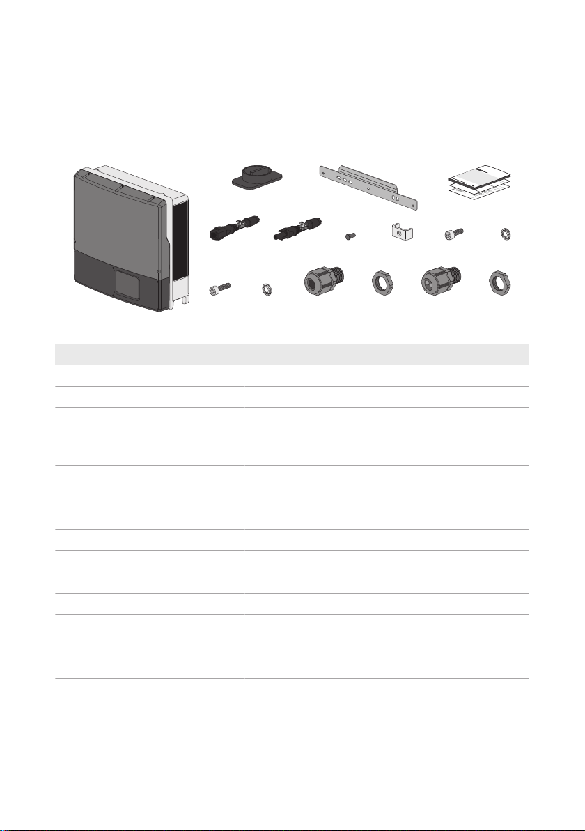
Check the scope of delivery for completeness and any externally visible damage. Contact your
distributor if the scope of delivery is incomplete or damaged.
The delivery may contain parts that are not required for the installation of this inverter.
Figure 1: Components included in the scope of delivery
Position Quantity Designation
A 1 Inverter
B 1 DC Load-Break Switch
C 1 Wall mounting bracket
D 1 Quick reference guide, supplementary sheet with default
settings, installation manual of the DC connector
E 6 Negative DC connector
F 6 Positive DC connector
G 12 Sealing plug
H 1 Clamping bracket
I 1 Cylindrical screw M6x16
K 1 Conical spring washer M6
L 2 Cylindrical screw M5x20*
M 2 Conical spring washer M5*
P 1 AC cable gland
Q 1 Counter nut
* Spare part for the enclosure lid
Operating manual STP15-25TL-30-BE-en-14 13
4 Product Overview
B
E
G
H
C
A
D
A
F
I
SMA Solar Technology AG
4 Product Overview
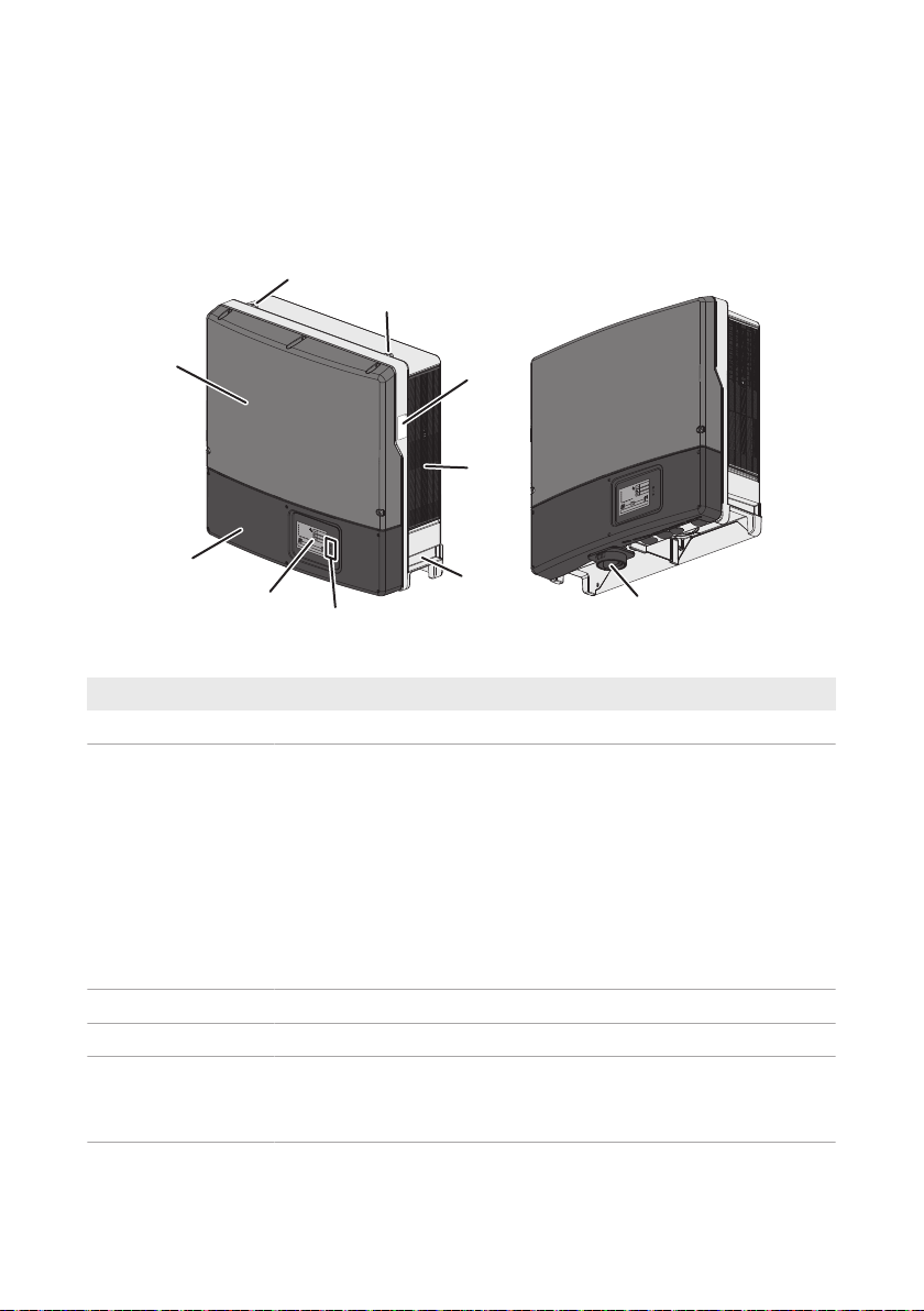
4.1 Product Description
The SunnyTripower is a transformerless PV inverter, with 2 MPPtrackers, that converts the direct
current of the PV array to grid-compliant, three-phase current and feeds it into the utility grid.
Figure 2: Design of the SunnyTripower
Position Designation
A Thread for screwing in two eye bolts for transport
B Type label
The type label uniquely identifies the inverter. You will require the information on the type label to use the product safely and when seeking customer support from the SMAServiceLine. You will find the following information on the type label:
• Device type (Model)
• Serial number (SerialNo.)
C Ventilation grid
D Recessed grip
E LEDs
• Date of manufacture
• Device-specific characteristics
The LEDs indicate the operating state of the inverter (see Section4.4 "LED
Signals", page18).
Operating manualSTP15-25TL-30-BE-en-1414
SMA Solar Technology AG
20 min
Position Designation
F Display (optional)
The display shows the current operating data and events or errors (see
Section10.1 "Event Messages", page54).
G Lower enclosure lid
H Upper enclosure lid
I DC Load-Break Switch
The inverter is equipped with a DC load-break switch. If the DC load-
break switch is set to the position I, it establishes a conductive connection
between the PV array and the inverter. Setting the DC load-break switch
to the O position interrupts the DC electric circuit and completely discon-
nects the PV array from the inverter. Disconnection takes place at all
poles.
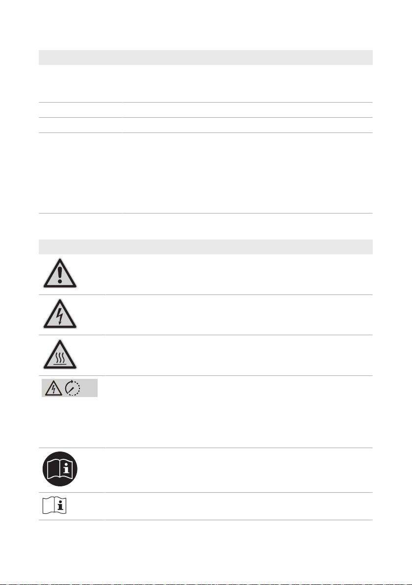
4.2 Symbols on the Product
Symbol Explanation
Beware of a danger zone
This symbol indicates that the product must be additionally grounded if addi-
tional grounding or equipotential bonding is required at the installation site.
Beware of electrical voltage
The product operates at high voltages.
4 Product Overview
Beware of hot surface
The product can get hot during operation.
Danger to life due to high voltages in the inverter; observe a waiting time of 5
minutes
High voltages that can cause lethal electric shocks are present in the live components of the inverter.
Prior to performing any work on the inverter, disconnect it from all voltage
sources as described in this document.
Observe the documentation
Observe all documentation supplied with the product.
Observe the documentation
Together with the red LED, this symbol indicates an error.
Operating manual STP15-25TL-30-BE-en-14 15
4 Product Overview
Symbol Explanation
Inverter
Together with the green LED, this symbol indicates the operating state of the in-
verter.
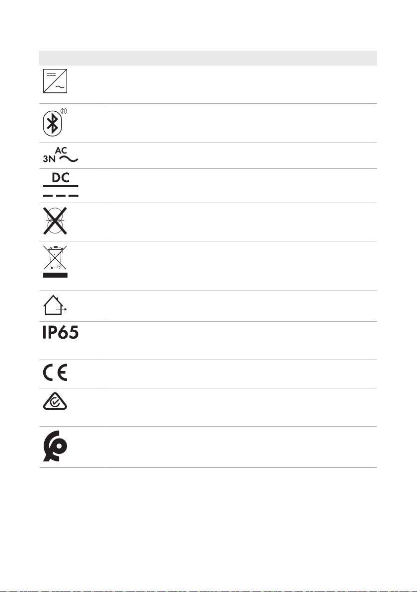
No function
Three-phase alternating current with neutral conductor
Direct current
The product is has no galvanic isolation.
WEEE designation
Do not dispose of the product together with the household waste but in accor-
dance with the disposal regulations for electronic waste applicable at the installation site.
The product is suitable for outdoor installation.
SMA Solar Technology AG
Degree of protectionIP65
The product is protected against the penetration of dust and water that is di-
rected as a jet against the enclosure from all directions.
CE marking
The product complies with the requirements of the applicable EU directives.
RCM (Regulatory Compliance Mark)
The product complies with the requirements of the applicable Australian standards.
The product complies with the Moroccan safety and EMC requirements for
electronic products.
4.3 Interfaces and Functions
The inverter can be equipped or retrofitted with the following interfaces and functions:
Operating manualSTP15-25TL-30-BE-en-1416

SMA Solar Technology AG
4 Product Overview
SMASpeedwire/Webconnect
The inverter is equipped with SMA Speedwire/Webconnect as standard. SMA Speedwire/
Webconnect is a type of communication based on the Ethernet standard. This enables inverteroptimized 10/100Mbit data transmission between Speedwire devices in PV systems and the
software Sunny Explorer. The Webconnect function enables direct data transmission between the
inverters of a small-scale system and the Internet portal SunnyPortal without any additional
communication device and for a maximum of 4 inverters per SunnyPortal system. In large-scale PV
power plants, data transmission to the Internet portal SunnyPortal is carried out via the
SMAClusterController. You can access your SunnyPortal system from any computer with an
Internet connection.
Webconnect enables - for PV systems operated in Italy - the connection or disconnection of the
inverter to or from the utility grid and the specifying of the frequency limits to be used via
IEC61850-GOOSE messages.
Modbus
The product is equipped with a Modbus interface. The Modbus interface is deactivated by default
and must be configured as needed.
The Modbus interface of the supported SMA products is designed for industrial use – via SCADA
systems, for example – and has the following tasks:
• Remote query of measured values
• Remote setting of operating parameters
• Setpoint specifications for system control
RS485 Interface
The inverter can communicate via cables with special SMA communication products via the RS485
interface (information on supported SMAproducts at www.SMA-Solar.com). The RS485 interface
can be retrofitted and can be used in place of the SMASpeedwire/Webconnect interface in the
inverter.
Grid management services
The product is equipped with service functions for grid management.
Depending on the requirements of the grid operator, you can activate and configure the functions
(e.g. active power limitation) via operating parameters.
SMA Power Control Module
The SMAPowerControlModule enables the inverter to implement grid management services and
is equipped with an additional multifunction relay (for information on installation and configuration,
see the installation manual of the SMAPowerControlModule). The SMAPowerControlModule
can be retrofitted.
Multifunction Relay
You can configure the multifunction relay for various operating modes. The multifunction relay is
used, for example, to switch fault indicators on or off (for information on installation and
configuration, see the installation manual of the multifunction relay). The multifunction relay can be
retrofitted.
Operating manual STP15-25TL-30-BE-en-14 17

4 Product Overview
SMA Solar Technology AG
SMAOptiTracGlobalPeak
SMAOptiTracGlobalPeak is an advancement of SMAOptiTrac and allows the operating point of
the inverter to follow the optimal operating point of the PV array (MPP) precisely at all times. In
addition, with the aid of SMAOptiTracGlobalPeak, the inverter detects several maximum power
points in the available operating range, such as may occur particularly with partially shaded
strings. SMA OptiTrac Global Peak is enabled by default.
Surge Arrester Type II
Surge arresters limit dangerous overvoltages. Surge arresters of typeII can be retrofitted.
QonDemand 24/7
The inverter can supply reactive power by means of QonDemand24/7 covering the entire unit
circle around the clock.
IntegratedPlantControl
The inverter can display the Q(V) characteristic curve specified by the grid operator by means of
IntegratedPlantControl without measuring on the grid-connection point. The inverter can
automatically compensate equipment installed between the inverter and the grid-connection point
after having activated the function (for information on the system configuration refer to the Technical
Information "Integrated Plant Control" at www.SMA-Solar.com).
SMA Smart Connected
SMA Smart Connected is the free monitoring of the inverter via the SMA SunnyPortal. Thanks to
SMA Smart Connected, the PV system operator and qualified person will be informed automatically
and proactively about inverter events that occur.
SMA Smart Connected is activated during registration in SunnyPortal. In order to use SMA Smart
Connected, it is necessary that the inverter is permanently connected to SunnyPortal and the data
of the PV system operator and qualified person is stored in SunnyPortal and up-to-date.
4.4 LED Signals
The LEDs indicate the operating state of the inverter.
LED Status Explanation
Green LED glowing Feed-in operation
If an event occurs during feed-in operation, an event message will be shown in the communication product (see
Section10.1, page54).
flashing The conditions for feed-in operation are not yet met. As
soon as the conditions are met, the inverter will start feedin operation.
Red LED glowing Error
An error has occurred. The error must be rectified by a
qualified person (see Section10.1, page54).
Blue LED - No function
Operating manualSTP15-25TL-30-BE-en-1418
SMA Solar Technology AG
5 Mounting
5 Mounting
5.1 Requirements for Mounting
Requirements for the Mounting Location:
WARNING
Danger to life due to fire or explosion
Despite careful construction, electrical devices can cause fires.
• Do not mount the product in areas containing highly flammable materials or gases.
• Do not mount the product in potentially explosive atmospheres.
☐ Do not mount the inverter on a pillar.
☐ A solid support surface must be available (e.g., concrete or masonry). When mounted on
drywall or similar materials, the product emits audible vibrations during operation which could
be perceived as annoying.
☐ The mounting location must be inaccessible to children.
☐ The mounting location must be suitable for the weight and dimensions of the product (see
Section14 "Technical Data", page84).
☐ The mounting location must not be exposed to direct solar irradiation. If the product is
exposed to direct solar irradiation, the exterior plastic parts might age prematurely and
overheating might occur. When becoming too hot, the product reduces its power output to
avoid overheating.
☐ The mounting location should be freely and safely accessible at all times without the need for
any auxiliary equipment (such as scaffolding or lifting platforms). Non-fulfillment of these
criteria may restrict servicing.
☐ All ambient conditions must be met (see Section14, page84).
☐ To ensure optimum operation, the ambient temperature should be between -25°C and 40°C.
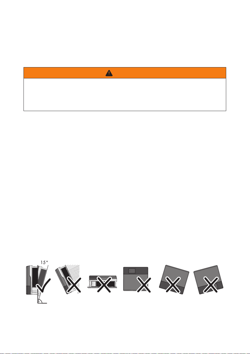
Permitted and prohibited mounting positions:
☐ The product may only be mounted in a permitted position. This will ensure that no moisture can
penetrate the product.
☐ The product should be mounted such that the LED signals can be read off without difficulty.
Figure 3: Permitted and prohibited mounting positions
Operating manual STP15-25TL-30-BE-en-14 19

5 Mounting
638
432
216 216
20
Ø 11
112
105 110
86 130 86
467
619
40
130
648
507
11
Dimensions for mounting:
SMA Solar Technology AG
Figure 4: Position of the anchoring points(Dimensions in mm)
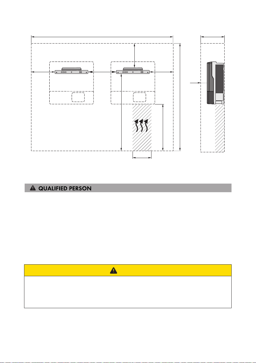
Recommended Clearances:
If you maintain the recommended clearances, adequate heat dissipation will be ensured. Thus, you
will prevent power reduction due to excessive temperature.
☐ Maintain the recommended clearances to walls as well as to other inverters or objects.
☐ If multiple inverters are mounted in areas with high ambient temperatures, increase the
clearances between the inverters and ensure sufficient fresh-air supply.
Operating manualSTP15-25TL-30-BE-en-1420
SMA Solar Technology AG
1382
2224
530
50
400
190
315
415
438
415
940
Figure 5: Recommended clearances(Dimensions in mm)
5.2 Mounting the Inverter
5 Mounting
Additionally required mounting material (not included in the scope of delivery):
☐ At least two screws suitable for the support surface (diameter: 10mm at maximum)
☐ At least two washers that are suitable for the screws (diameter: 30mm at maximum)
☐ If necessary, two screw anchors suitable for the support surface and the screws
☐ For transporting the inverter with a crane: two eye bolts suitable for the weight of the inverter
(size: M10)
☐ To secure the inverter from being lifted off: two screws suitable for the support surface, two
washers suitable for the screws and - depending on the support surface - two screw anchors
suitable for the support surface and the screws
CAUTION
Risk of injury when lifting the inverter, or if it is dropped
The inverter weighs 61kg. There is risk of injury if the inverter is lifted incorrectly or dropped
while being transported or when attaching it to or removing it from the wall mounting bracket.
• Transport the inverter always as described below.
Operating manual STP15-25TL-30-BE-en-14 21
5 Mounting
SMA Solar Technology AG
CAUTION
Risk of burns due to hot enclosure parts
Some parts of the enclosure can get hot during operation.
• Mount the inverter in such a way that it cannot be touched inadvertently during operation.
Procedure:
1.
Risk of injury due to damaged cables
There may be power cables or other supply lines (e.g. gas or water) routed in the wall.
• Ensure that no lines are laid in the wall which could be damaged when drilling holes.
2. Align the wall mounting bracket horizontally on the wall and use it to mark the position of the
drill holes. Use at least one hole on the right-hand and left-hand side in the wall mounting
bracket.
3. If the inverter is to be secured from being lifted off of the wall mounting bracket, mark the
position of the drill holes for the screw that attaches the inverter to the wall mounting bracket.
Observe the dimensions of the two anchoring points at the bottom of the inverter rear panel.
4. Set the wall mounting bracket aside and drill the marked holes.
5. Insert screw anchors into the drill holes if the support surface requires them.
6. Secure the wall mounting bracket horizontally using screws and washers.
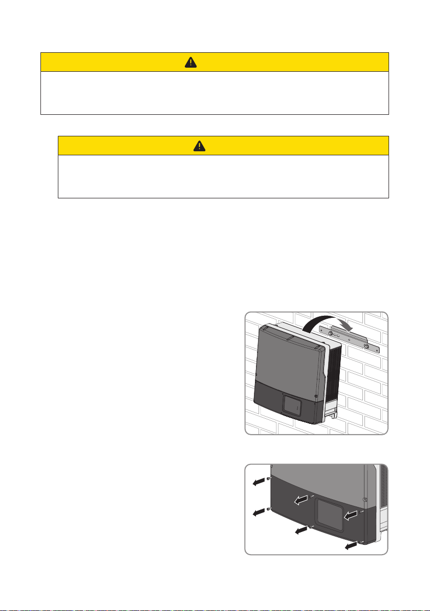
7. Hook the inverter into the wall mounting bracket.
CAUTION
8. If the inverter has been transported with a crane, remove the eye bolts from the threads on the
top of the inverter and reinsert the filler plugs.
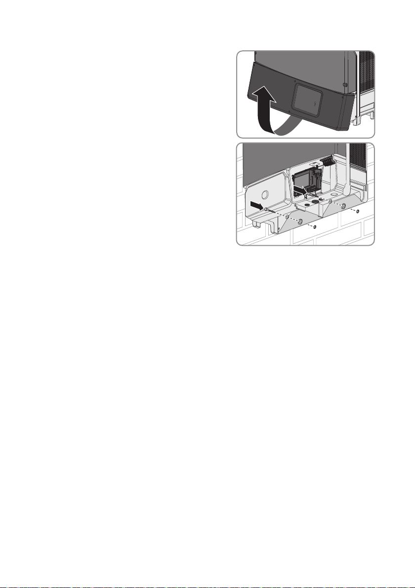
9. Remove all six screws from the lower enclosure lid
using an Allen key (AF 3).
Operating manualSTP15-25TL-30-BE-en-1422
SMA Solar Technology AG
10. Flip the lower enclosure lid up and remove it.
11. In order to secure the inverter from being lifted off
the wall accidentally, attach it to the wall with
suitable mounting material. Use both of the lower
drill holes on the rear panel of the inverter.
12. Ensure that the inverter is securely in place.
5 Mounting
Operating manual STP15-25TL-30-BE-en-14 23
6 Electrical Connection
A
B
D
E
F
G
C
SMA Solar Technology AG
6 Electrical Connection
6.1 Overview of the Connection Area
6.1.1 View from Below
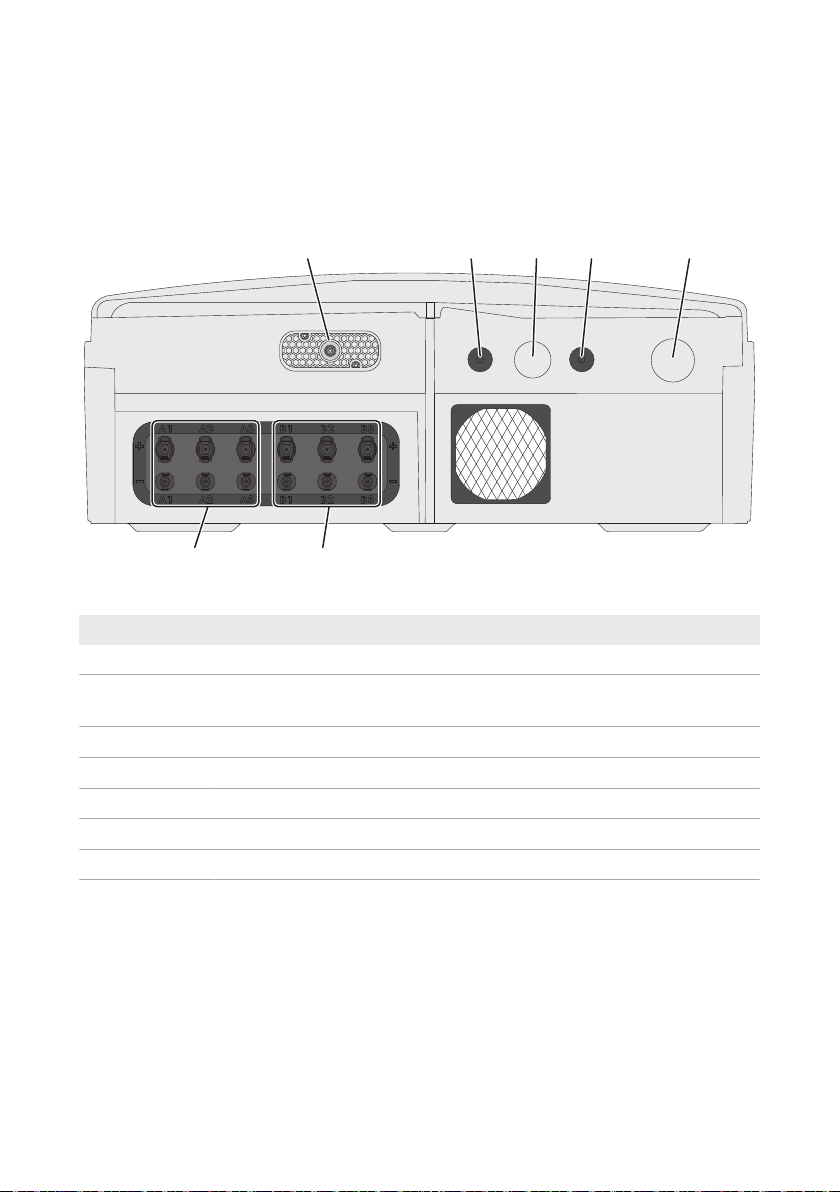
Figure 6: Enclosure openings at the bottom of the inverter
Position Designation
A Pin connector for the DC load-break switch
B Enclosure opening M20 with filler plug for the connection cable of the multi-
function relay or SMAPowerControlModule
C Enclosure opening M32 with filler plug for the data cables or network cables
D Enclosure opening M20 with filler plug for the data cables or network cables
E Enclosure opening for the AC connection
F Positive and negative DC connectors, input B
G Positive and negative DC connectors, input A
Operating manualSTP15-25TL-30-BE-en-1424
SMA Solar Technology AG
6 Electrical Connection
6.1.2 Interior View
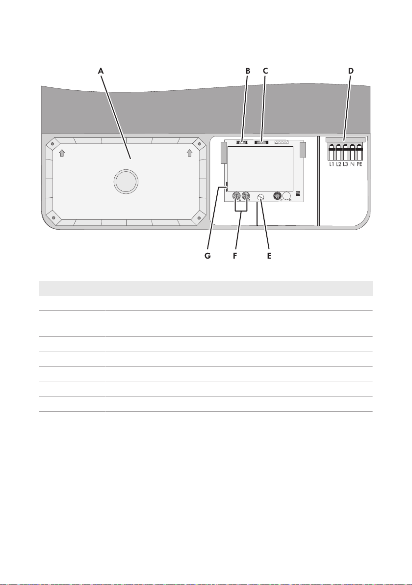
Figure 7: Connection areas in the interior of the inverter
Position Designation
A DC protective cover
B Pin connector for connecting the multifunction relay or the SMA Power Control
Module
C Pin connector for connecting the communication interface
D Connecting terminal plate for connecting the AC cable
E Screw to release and attach the communication board
F Rotary switch A and B for setting the country data set
G Slot for the SD memory card (for service purposes)
Operating manual STP15-25TL-30-BE-en-14 25

6 Electrical Connection
SMA Solar Technology AG
6.2 AC Connection
6.2.1 Requirements for the AC Connection
Cable requirements:
☐ The conductors must consist of copper.
☐ External diameter: 14mm to 25mm
☐ Conductor cross-section: 6mm² to 16mm²
☐ Maximum conductor cross-section with bootlace ferrule: 10mm²
☐ Insulation stripping length: 12mm
☐ The cable must be dimensioned in accordance with the local and national directives for the
dimensioning of cables. The requirements for the minimum wire size derive from these
directives. Examples of factors influencing cable dimensioning are: nominal AC current, type of
cable, routing method, cable bundling, ambient temperature and maximum desired line losses
(for calculation of line losses, see the design software "SunnyDesign" from software
version2.0 at www.SMA-Solar.com).
Load-break switch and cable protection:
NOTICE
Damage to the inverter due to the use of screw-type fuses as load-break
switches
Screw-type fuses (e.g. DIAZED fuse or NEOZED fuse) are not load-break switches.
• Do not use screw-type fuses as load-break switches.
• Use a load-break switch or circuit breaker as a load disconnection unit (for information and
design examples, see the Technical Information "Circuit Breaker" at www.SMA-Solar.com).
☐ In PV systems with multiple inverters, protect each inverter with a separate three-phase circuit
breaker. Make sure to observe the maximum permissible fuse protection (see Section14
"Technical Data", page84). This will prevent residual voltage from being present at the
corresponding cable after disconnection.
☐ Loads installed between the inverter and the circuit breaker must be fused separately.
Residual-current monitoring unit:
☐ If an external residual-current device is required, install a residual-current device which trips at
a residual current of 100mA or higher (for details on selecting a residual-current device, see
the Technical Information "Criteria for Selecting a Residual-Current Device" at www.SMASolar.com).
Operating manualSTP15-25TL-30-BE-en-1426

SMA Solar Technology AG
Overvoltage category:
The inverter can be used in grids of overvoltage categoryIII or lower in accordance with
IEC60664-1. That means that the inverter can be permanently connected to the grid-connection
point of a building. In case of installations with long outdoor cabling routes, additional measures to
reduce overvoltage categoryIV to overvoltage categoryIII are required (see the Technical
Information "Overvoltage Protection" at www.SMA-Solar.com).
6 Electrical Connection
Additional grounding:
Safety in accordance with IEC62109
The inverter is not equipped with a grounding conductor monitoring device. In order to
guarantee safety in accordance with IEC62109, you must take one of the following
measures:
• Connect a grounding conductor made of copper wire with a cross-section of at least
10mm² to the connecting terminal plate for the AC cable.
• Connect additional grounding with the same cross-section as the connected grounding
conductor to the connecting terminal plate for the AC cable (see Section6.2.3
"Connecting Additional Grounding", page29). This prevents touch current if the
grounding conductor at the connecting terminal plate for the AC cable fails.
Connection of additional grounding
In some countries, additional grounding is generally required. In each case, observe the
locally applicable regulations.
• If additional grounding is required, connect an additional grounding that has at least the
same cross-section as the connected grounding conductor to the connecting terminal
plate for the AC cable (see Section6.2.3, page29). This prevents touch current if the
grounding conductor at the connecting terminal plate for the AC cable fails.
6.2.2 Connecting the Inverter to the Utility Grid
Requirements:
☐ The connection requirements of the grid operator must be met.
☐ The grid voltage must be in the permissible range. The exact operating range of the inverter is
specified in the operating parameters.
Procedure:
1. Disconnect the circuit breaker from all three line conductors and secure against reconnection.
2. If the lower enclosure lid is mounted, loosen all screws of the lower enclosure lid using an
Allen key (AF3) and lift the enclosure lid from below and remove it.
3. Remove the adhesive tape from the enclosure opening for the AC cable.
Operating manual STP15-25TL-30-BE-en-14 27
6 Electrical Connection
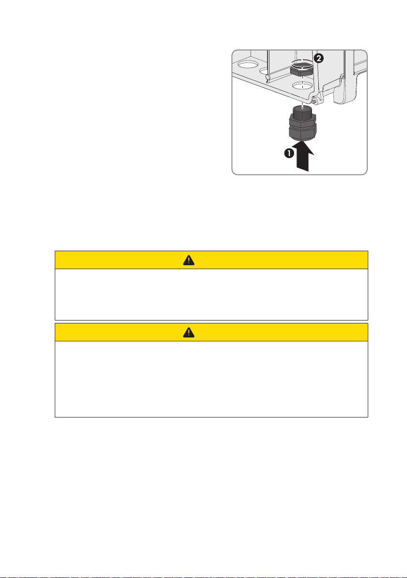
4. Insert the cable gland from the outside into the
enclosure opening and tighten it from the inside with
the counter nut.
5. Route the AC cable into the inverter through the cable gland. If necessary, slightly loosen the
swivel nut of the cable gland.
6. Dismantle the AC cable.
7. Shorten L1, L2, L3 and N by 5mm each so that the grounding conductor is 5mm longer.
8. Strip off the insulation of L1, L2, L3, N and PE by 12mm.
9. Push the safety levers of the AC terminal block right up to the stop.
10.
CAUTION
SMA Solar Technology AG
Risk of fire if two conductors are connected to one terminal
If you connect two conductors to a terminal, a fire can occur due to a bad electrical
connection.
• Never connect more than one conductor per terminal.
11.
CAUTION
Danger of crushing when locking levers snap shut
The locking levers close by snapping down fast and hard.
• Press the locking levers of the terminal block for the AC cable down with your thumb
only.
• Do not grip the entire terminal block for the AC cable.
• Do not place your fingers under the locking levers.
12. Connect PE, N, L1, L2 and L3 according to the labeling to the terminal block for the AC cable
and push the safety levers down. The direction of the rotating magnetic field of L1, L2 and L3
is not relevant.
13. Make sure that all conductors are securely in place.
Operating manualSTP15-25TL-30-BE-en-1428
SMA Solar Technology AG
14. Tighten the swivel nut of the cable gland.
6 Electrical Connection
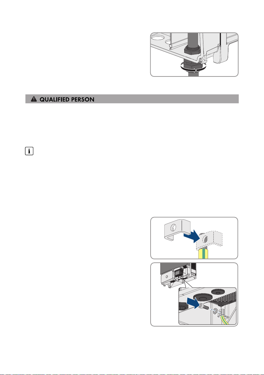
6.2.3 Connecting Additional Grounding
If additional grounding or equipotential bonding is required locally, you can connect additional
grounding to the inverter. This prevents touch current if the grounding conductor at the terminal for
the AC cable fails. The required clamping bracket, the screw and the conical spring washer are
part of the scope of delivery of the inverter.
Cable requirements:
Use of fine-stranded conductors
You can use an inflexible or a flexible, fine-stranded conductor.
• When using a fine-stranded conductor, it has to be double crimped by a ring terminal lug.
Make sure that no insulated conductor is visible when pulling or bending. This will ensure
sufficient strain relief by means of the ring terminal lug.
☐ Grounding cable cross-section: max. 16mm²
Procedure:
1. Strip the grounding cable insulation.
2. Lead the clamping bracket over the grounding
cable. Arrange the grounding cable on the left-hand
side.
3. Screw the clamping bracket tight using the M6x16
cylindrical screw and the conical spring washer M6
(torque: 6Nm). The teeth of the conical spring
washer must face the clamping bracket.
Operating manual STP15-25TL-30-BE-en-14 29
 Loading...