

SMA Solar Technology AG GRID-CONNECT-BOX 12 Operating Manual
GRID-BOX-12-3-20-BE-en-11 | Version 1.1 ENGLISH
Operating Manual
GRID-CONNECT-BOX 12

Legal Provisions SMA Solar Technology AG
2 GRID-BOX-12-3-20-BE-en-11 Operating Manual
Legal Provisions
The information contained in this document is the property of SMA Solar Technology AG. Publishing its content, either
partially or in full, requires the written permission of SMA Solar Technology AG. Any internal company copying of the
document for the purposes of evaluating the product or its correct implementation is allowed and does not require
permission.
SMA Warranty
You can download the current warranty conditions from the Internet at www.SMA-Solar.com.
Trademarks
All trademarks are recognized, even if not explicitly identified as such. A lack of identification does not mean that a
product or symbol is not trademarked.
The BLUETOOTH
®
word mark and logos are registered trademarks owned by Bluetooth SIG, Inc. and any use of these
marks by SMA Solar Technology AG is under license.
Modbus
®
is a registered trademark of Schneider Electric and is licensed by the Modbus Organization, Inc.
QR Code is a registered trademark of DENSO WAVE INCORPORATED.
Phillips
®
and Pozidriv® are registered trademarks of Phillips Screw Company.
Torx
®
is a registered trademark of Acument Global Technologies, Inc.
SMA Solar Technology AG
Sonnenallee 1
34266 Niestetal
Germany
Tel. +49 561 9522-0
Fax +49 561 9522-100
www.SMA.de
E-mail: info@SMA.de
© 2004 to 2016 SMA Solar Technology AG. All rights reserved.

SMA Solar Technology AG Table of Contents
Operating Manual GRID-BOX-12-3-20-BE-en-11 3
Table of Contents
1 Information on this Document. . . . . . . . . . . . . . . . . . . . . . . . . . . . . . . . . . . . . . . . . . . . . . . . . . . . . 5
1.1 Validity . . . . . . . . . . . . . . . . . . . . . . . . . . . . . . . . . . . . . . . . . . . . . . . . . . . . . . . . . . . . . . . . . . . . . . . . . . . . . . 5
1.2 Target Group . . . . . . . . . . . . . . . . . . . . . . . . . . . . . . . . . . . . . . . . . . . . . . . . . . . . . . . . . . . . . . . . . . . . . . . . . 5
1.3 Additional Information . . . . . . . . . . . . . . . . . . . . . . . . . . . . . . . . . . . . . . . . . . . . . . . . . . . . . . . . . . . . . . . . . . 5
1.4 Symbols . . . . . . . . . . . . . . . . . . . . . . . . . . . . . . . . . . . . . . . . . . . . . . . . . . . . . . . . . . . . . . . . . . . . . . . . . . . . . 5
1.5 Typographies . . . . . . . . . . . . . . . . . . . . . . . . . . . . . . . . . . . . . . . . . . . . . . . . . . . . . . . . . . . . . . . . . . . . . . . . . 6
1.6 Nomenclature. . . . . . . . . . . . . . . . . . . . . . . . . . . . . . . . . . . . . . . . . . . . . . . . . . . . . . . . . . . . . . . . . . . . . . . . . 6
2 Safety . . . . . . . . . . . . . . . . . . . . . . . . . . . . . . . . . . . . . . . . . . . . . . . . . . . . . . . . . . . . . . . . . . . . . . . . 7
2.1 Intended Use . . . . . . . . . . . . . . . . . . . . . . . . . . . . . . . . . . . . . . . . . . . . . . . . . . . . . . . . . . . . . . . . . . . . . . . . . 7
2.2 Safety Information . . . . . . . . . . . . . . . . . . . . . . . . . . . . . . . . . . . . . . . . . . . . . . . . . . . . . . . . . . . . . . . . . . . . . 9
3 Scope of Delivery. . . . . . . . . . . . . . . . . . . . . . . . . . . . . . . . . . . . . . . . . . . . . . . . . . . . . . . . . . . . . . 10
4 Product Description . . . . . . . . . . . . . . . . . . . . . . . . . . . . . . . . . . . . . . . . . . . . . . . . . . . . . . . . . . . . 11
4.1 Grid-Connect-Box . . . . . . . . . . . . . . . . . . . . . . . . . . . . . . . . . . . . . . . . . . . . . . . . . . . . . . . . . . . . . . . . . . . . . 11
4.2 Type Label . . . . . . . . . . . . . . . . . . . . . . . . . . . . . . . . . . . . . . . . . . . . . . . . . . . . . . . . . . . . . . . . . . . . . . . . . . 13
5 Installation . . . . . . . . . . . . . . . . . . . . . . . . . . . . . . . . . . . . . . . . . . . . . . . . . . . . . . . . . . . . . . . . . . . 14
5.1 Storing the Grid-Connect-Box. . . . . . . . . . . . . . . . . . . . . . . . . . . . . . . . . . . . . . . . . . . . . . . . . . . . . . . . . . . . 14
5.2 Requirements for Mounting. . . . . . . . . . . . . . . . . . . . . . . . . . . . . . . . . . . . . . . . . . . . . . . . . . . . . . . . . . . . . . 14
5.3 Preparing the Mounting Location . . . . . . . . . . . . . . . . . . . . . . . . . . . . . . . . . . . . . . . . . . . . . . . . . . . . . . . . . 15
5.4 Transport. . . . . . . . . . . . . . . . . . . . . . . . . . . . . . . . . . . . . . . . . . . . . . . . . . . . . . . . . . . . . . . . . . . . . . . . . . . . 15
5.4.1 Transport Options . . . . . . . . . . . . . . . . . . . . . . . . . . . . . . . . . . . . . . . . . . . . . . . . . . . . . . . . . . . . . . . . . . . . . . .15
5.4.2 Transporting and Mounting the Grid-Connect-Box . . . . . . . . . . . . . . . . . . . . . . . . . . . . . . . . . . . . . . . . . . . . . .16
6 Electrical Connection . . . . . . . . . . . . . . . . . . . . . . . . . . . . . . . . . . . . . . . . . . . . . . . . . . . . . . . . . . . 17
6.1 Overview of the Connection Area . . . . . . . . . . . . . . . . . . . . . . . . . . . . . . . . . . . . . . . . . . . . . . . . . . . . . . . . 17
6.1.1 Components and Terminals. . . . . . . . . . . . . . . . . . . . . . . . . . . . . . . . . . . . . . . . . . . . . . . . . . . . . . . . . . . . . . . .17
6.1.2 Enclosure Openings in the Floor . . . . . . . . . . . . . . . . . . . . . . . . . . . . . . . . . . . . . . . . . . . . . . . . . . . . . . . . . . . .18
6.2 Deactivating All-Pole Disconnection . . . . . . . . . . . . . . . . . . . . . . . . . . . . . . . . . . . . . . . . . . . . . . . . . . . . . . . 18
6.3 Connecting the Multicluster-Box . . . . . . . . . . . . . . . . . . . . . . . . . . . . . . . . . . . . . . . . . . . . . . . . . . . . . . . . . . 18
6.4 Connecting the Utility Grid . . . . . . . . . . . . . . . . . . . . . . . . . . . . . . . . . . . . . . . . . . . . . . . . . . . . . . . . . . . . . . 19
6.5 Connecting the Control Cables . . . . . . . . . . . . . . . . . . . . . . . . . . . . . . . . . . . . . . . . . . . . . . . . . . . . . . . . . . 19
6.6 Mounting the Kick Plates . . . . . . . . . . . . . . . . . . . . . . . . . . . . . . . . . . . . . . . . . . . . . . . . . . . . . . . . . . . . . . . 20
7 Preparing the Multicluster System for Commissioning . . . . . . . . . . . . . . . . . . . . . . . . . . . . . . . . 21
8 Disconnecting the Grid-Connect-Box and Multicluster System from Voltage Sources. . . . . . . 22
9 Periodic Actions . . . . . . . . . . . . . . . . . . . . . . . . . . . . . . . . . . . . . . . . . . . . . . . . . . . . . . . . . . . . . . . 23
9.1 Removing the Protective Cover . . . . . . . . . . . . . . . . . . . . . . . . . . . . . . . . . . . . . . . . . . . . . . . . . . . . . . . . . . . 23
9.2 Mounting the Protective Cover . . . . . . . . . . . . . . . . . . . . . . . . . . . . . . . . . . . . . . . . . . . . . . . . . . . . . . . . . . . 24
9.3 Inserting the Cables . . . . . . . . . . . . . . . . . . . . . . . . . . . . . . . . . . . . . . . . . . . . . . . . . . . . . . . . . . . . . . . . . . . 25
9.4 Connection to Spring-Cage Terminals . . . . . . . . . . . . . . . . . . . . . . . . . . . . . . . . . . . . . . . . . . . . . . . . . . . . . 26
9.4.1 Connecting Power Cables to Spring-Cage Terminals . . . . . . . . . . . . . . . . . . . . . . . . . . . . . . . . . . . . . . . . . . . .26
9.4.2 Connecting Control Cables to Spring-Cage Terminals . . . . . . . . . . . . . . . . . . . . . . . . . . . . . . . . . . . . . . . . . . . 27

Table of Contents SMA Solar Technology AG
4 GRID-BOX-12-3-20-BE-en-11 Operating Manual
10 Maintenance . . . . . . . . . . . . . . . . . . . . . . . . . . . . . . . . . . . . . . . . . . . . . . . . . . . . . . . . . . . . . . . . . .28
10.1 Testing the Residual-Current Device. . . . . . . . . . . . . . . . . . . . . . . . . . . . . . . . . . . . . . . . . . . . . . . . . . . . . . . 28
10.2 Testing the Surge Arrester . . . . . . . . . . . . . . . . . . . . . . . . . . . . . . . . . . . . . . . . . . . . . . . . . . . . . . . . . . . . . . 29
10.3 Maintenance Work Every 12 Months . . . . . . . . . . . . . . . . . . . . . . . . . . . . . . . . . . . . . . . . . . . . . . . . . . . . . 29
11 Decommissioning . . . . . . . . . . . . . . . . . . . . . . . . . . . . . . . . . . . . . . . . . . . . . . . . . . . . . . . . . . . . . .31
11.1 Disassembling the Grid-Connect-Box . . . . . . . . . . . . . . . . . . . . . . . . . . . . . . . . . . . . . . . . . . . . . . . . . . . . . . 31
11.2 Disposing of the Grid-Connect-Box . . . . . . . . . . . . . . . . . . . . . . . . . . . . . . . . . . . . . . . . . . . . . . . . . . . . . . . 31
12 Technical Data. . . . . . . . . . . . . . . . . . . . . . . . . . . . . . . . . . . . . . . . . . . . . . . . . . . . . . . . . . . . . . . . .32
13 Contact. . . . . . . . . . . . . . . . . . . . . . . . . . . . . . . . . . . . . . . . . . . . . . . . . . . . . . . . . . . . . . . . . . . . . . .35
SMA Solar Technology AG 1 Information on this Document
Operating Manual GRID-BOX-12-3-20-BE-en-11 5
1 Information on this Document
1.1 Validity
This document is valid for the device type "GRID-CONNECT-BOX 12.3-20" (Grid-Connect-Box 12).
1.2 Target Group
The activities described in this document must be performed by qualified persons only. Qualified persons must have the
following skills:
• Training in how to deal with the dangers and risks associated with installing and operating electrical devices and
batteries
• Training in the installation and commissioning of electrical devices
• Knowledge of and adherence to the local standards and directives
• Knowledge of and compliance with this document and all safety information
1.3 Additional Information
Links to additional information can be found at www.SMA-Solar.com:
1.4 Symbols
Document title Document type
MULTICLUSTER-BOX 12 Installation – circuitry overview
MULTICLUSTER-BOX 12 Operating manual
Symbol Explanation
'$1*(5
Indicates a hazardous situation that, if not avoided, will result in death or serious injury
:$51,1*
Indicates a hazardous situation that, if not avoided, can result in death or serious injury
&$87,21
Indicates a hazardous situation that, if not avoided, can result in minor or moderate injury
/05*$&
Indicates a situation that, if not avoided, can result in property damage
Information that is important for a specific topic or goal, but is not safety-relevant
Indicates a requirement for meeting a specific goal
Desired result
✖ A problem that might occur

1 Information on this Document SMA Solar Technology AG
6 GRID-BOX-12-3-20-BE-en-11 Operating Manual
1.5 Typographies
1.6 Nomenclature
Typography Application Example
bold • Display messages
• Parameter
•Terminals
•Slots
• Elements to be selected or
entered
• Connect the neutral conductor to the
spring-cage terminal N at terminal X301:6.
• Connect the line conductors to the
spring-cage terminals L1, L2 and L3 at the
terminals X301:8-10.
> • Connects several elements to be
selected
–
[Button/Key] • Button on the device to be
selected or pressed
•Press the [TEST] button.
Complete designation Designation in this document
Grid-Connect-Box12 Grid-Connect-Box
Multicluster-Box 12 Multicluster-Box
SMA Solar Technology AG 2 Safety
Operating Manual GRID-BOX-12-3-20-BE-en-11 7
2 Safety
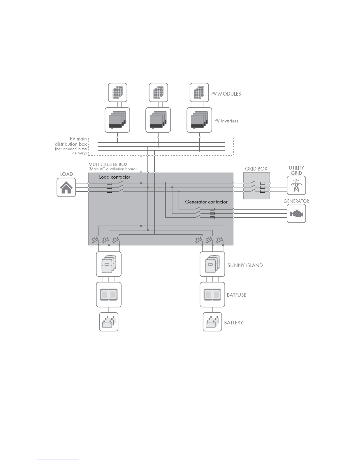
2.1 Intended Use
The Grid-Connect-Box is an automatic transfer switch which enables the safe operation of the utility grid and an electricity
generator as energy sources of an SMA multicluster system.
Figure1: Circuitry principle of a multicluster system with the Grid-Connect-Box
The technical connection requirements of the grid operator and the local standards and directives specify whether the
multicluster system, in the event of grid failure, disconnects from the utility grid at all poles or only the line conductors.
The Grid-Connect-Box is always supplied with an all-pole disconnection function. If all-pole disconnection is not permitted,
the Grid-Connect-Box all-pole disconnection function must be deactivated(see Section6.2, page18).
If the Grid-Connect-Box is used with all-pole disconnection, the utility grid must be either a TN-S, TN-C-S or TT system.
If the Grid-Connect-Box is used without all-pole disconnection, the utility grid must be a TN-C-S system (for grounding in
the multicluster system, see the Multicluster-Box operating manual).
Do not exceed the maximum AC connection power of the Grid-Connect-Box. Cables with copper conductors must be
used for the installation.

2 Safety SMA Solar Technology AG
8 GRID-BOX-12-3-20-BE-en-11 Operating Manual
In terms of interference immunity, the product is suitable for EMC environment A, and in terms of EMC emissions, it is
suitable for EMC environment B* .
The Grid-Connect-Box may only be commissioned in conjunction with the Multicluster-Box.
The Grid-Connect-Box is designed for use at altitudes of up to 3000 m above Mean Sea Level. If you would like to use
the Grid-Connect-Box at altitudes above 3000 m, contact Service (see Section13, page35).
The Grid-Connect-Box is suitable for indoor use. The product may only be operated at temperatures between −25°C and
+60°C.
All work on the product must only be performed using appropriate tools and in compliance with the ESD protection
regulations.
Suitable personal protective equipment must be worn by all persons working on or with the product.
Use this product only in accordance with the information provided in the enclosed documentation and with the locally
applicable standards and directives. Any other application may cause personal injury or property damage. Alterations
to the product, e.g. modifications or conversions, are only permitted with the express written permission of
SMA Solar Technology AG. Unauthorized alterations will void guarantee and warranty claims and will usually void the
operation license. SMA Solar Technology AG shall not be held liable for any damage caused by such alterations.
Any use of the product other than that described in the Intended Use section does not qualify as the intended use.
The enclosed documentation is an integral part of this product. Keep the documentation in a convenient place for future
reference and observe all instructions contained therein.
The type label must remain permanently attached to the product.
* In accordance with IEC 61439-1:2011

SMA Solar Technology AG 2 Safety
Operating Manual GRID-BOX-12-3-20-BE-en-11 9
2.2 Safety Information
This Section contains safety information that must be observed at all times during work on or with the product.
To prevent personal injury and property damage and to ensure long-term operation of the product, read this Section
carefully and observe all safety information at all times.
'$1*(5
Danger to life due to electric shock
High voltages are present in the Grid-Connect-Box and the multicluster system. Touching live components results in
death or serious injury due to electric shock.
• Disconnect the Grid-Connect-Box and multicluster system from all voltage sources before carrying out any work
on the Grid-Connect-Box (see Section8, page22).
• Only operate the Grid-Connect-Box with its protective cover in place.
• Work on the Grid-Connect-Box may only be performed by qualified persons.
• Do not touch any live components in the Grid-Connect-Box or any other components in the multicluster system.
&$87,21
Risk of injury if the Grid-Connect-Box tips over
The Grid-Connect-Box is heavy and may tip over if not properly fastened to the support surface. This can result in injuries
due to crushing.
• Upon installation, attach the Grid-Connect-Box to the support surface.
&$87,21
Risk of burns due to hot components
Components and terminals inside the Grid-Connect-Box can become hot during operation. Touching hot components
can cause burns.
• Only operate the Grid-Connect-Box with its protective cover in place.
• Prior to removing the protective cover, let the Grid-Connect-Box cool down.
Effects of an emergency disconnection
Emergency disconnection of the Sunny Island triggers the uncontrolled shutdown of the system, resulting in any
unsaved data being lost.
• Only use the emergency disconnection to avoid danger or consequential damage.
• In the event of an emergency disconnection, always check whether any fuse elements in the Grid-Connect-Box,
such as circuit breakers, have tripped.
If any fuse elements have tripped, reactivate these fuse elements.
3 Scope of Delivery SMA Solar Technology AG
10 GRID-BOX-12-3-20-BE-en-11 Operating Manual
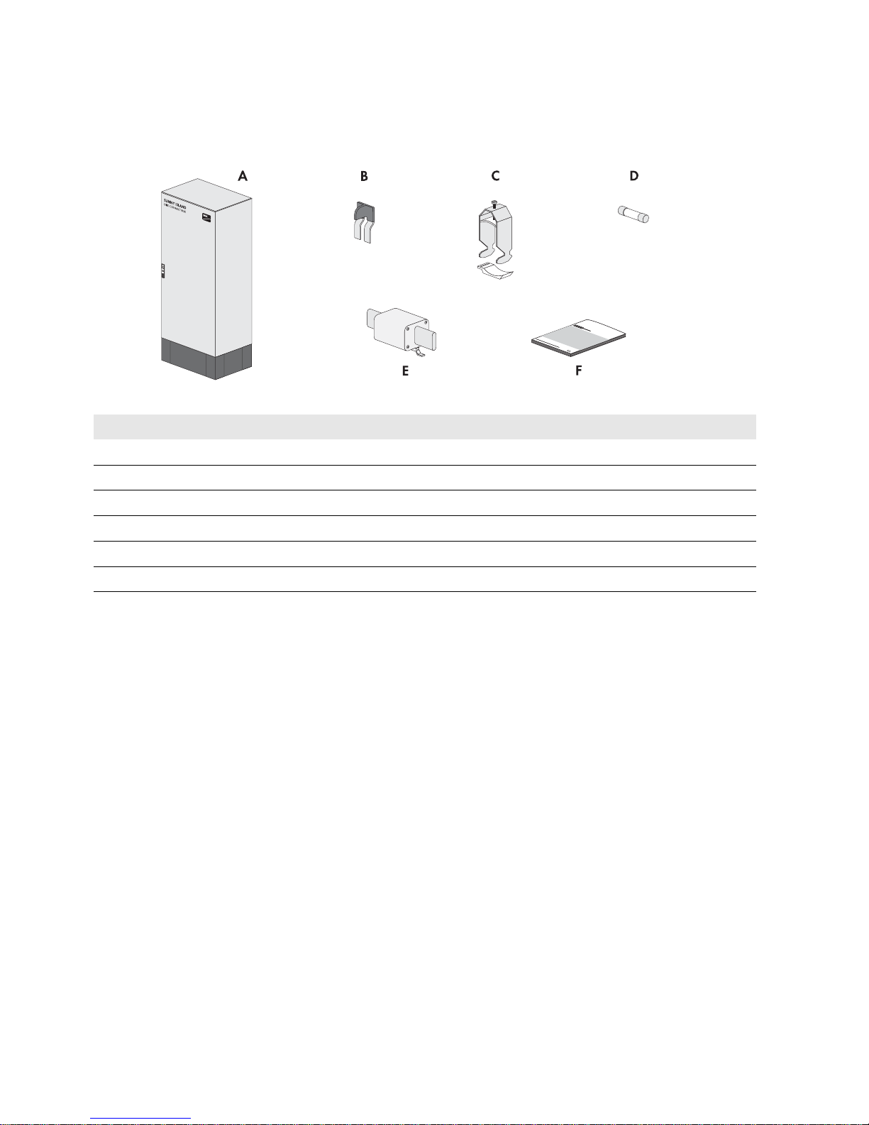
3 Scope of Delivery
Check the scope of delivery for completeness and any externally visible damage. Contact your distributor if the scope of
delivery is incomplete or damaged.
Figure2: Components included in the scope of delivery
Position Quantity Designation
A 1 Grid-Connect-Box
B 1 Two-pole N bridge
C 10 Strain relief with counter-sleeve (22 mm to 28 mm)
D 2 Fuse link (1 A, tripping characteristic gG)
E 2 LV/HRC fuse link (200 A, tripping characteristic: gG)
F 1 Operating manual
SMA Solar Technology AG 4 Product Description
Operating Manual GRID-BOX-12-3-20-BE-en-11 11
4 Product Description
4.1 Grid-Connect-Box
The Grid-Connect-Box is an automatic transfer switch which enables the safe operation of the utility grid and an electricity
generator as energy sources of an SMA Multicluster System.
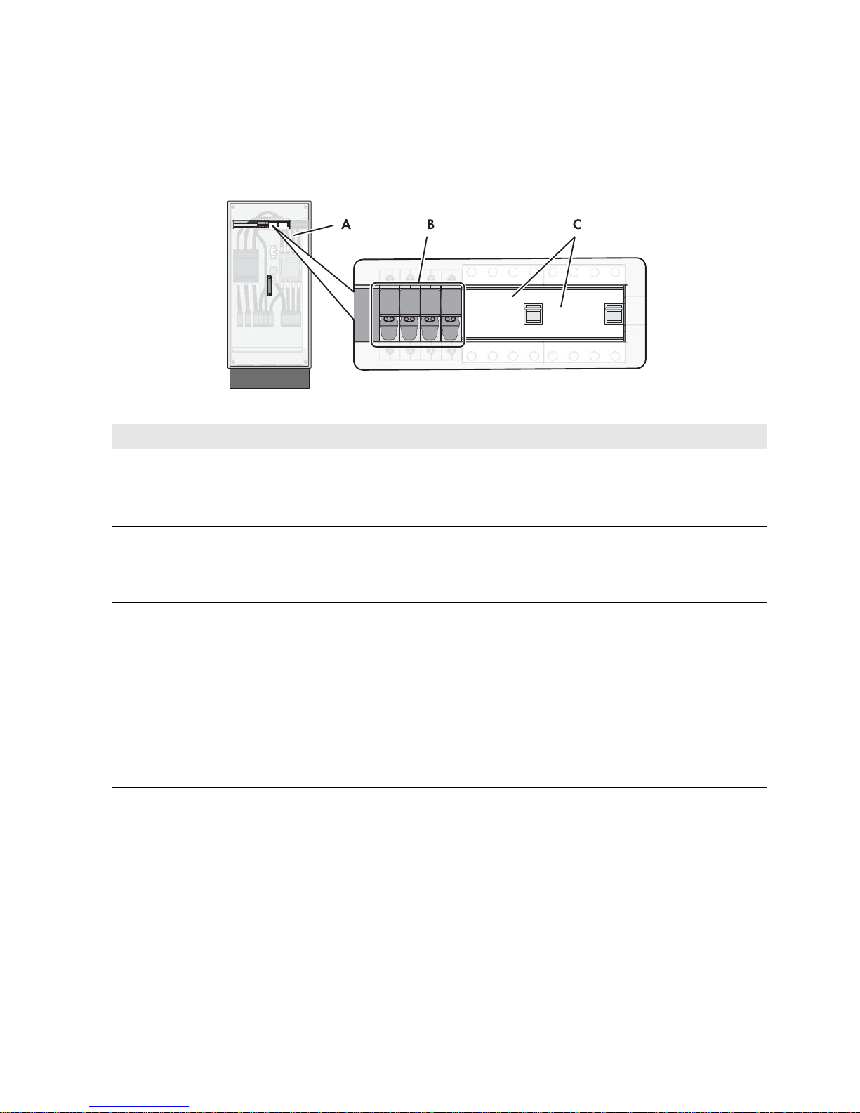
Figure3: Grid-Connect-Box with cabinet door open
Position Designation Explanation
A Protective cover Prevents inadvertent contact with live components during
operation and thus protects from electric shocks. The protective
cover must always be in position when the Grid-Connect-Box is in
operation.
B Fuse holder 1 A Receptacle for cylindrical thermal fuses (1 A, tripping
characteristic gG). The thermal fuses protect the connected
conductors from excessive heat build-up due to overload or short
circuits.
C Residual-current device Protects against electric shock and is always used in addition to
existing protective measures such as insulation or protective
grounding. As soon as a dangerous touch voltage occurs, the
residual-current device disconnects all poles of the loads.
This is achieved by means of a summation current transformer in
the residual-current device which detects the electric currents in
the conductors L1, L2, L3 and N. In the normal operating state,
the sum of these currents equals zero. Under fault conditions a
differential current is formed which trips the residual-current
device.
4 Product Description SMA Solar Technology AG
12 GRID-BOX-12-3-20-BE-en-11 Operating Manual
Residual-current device
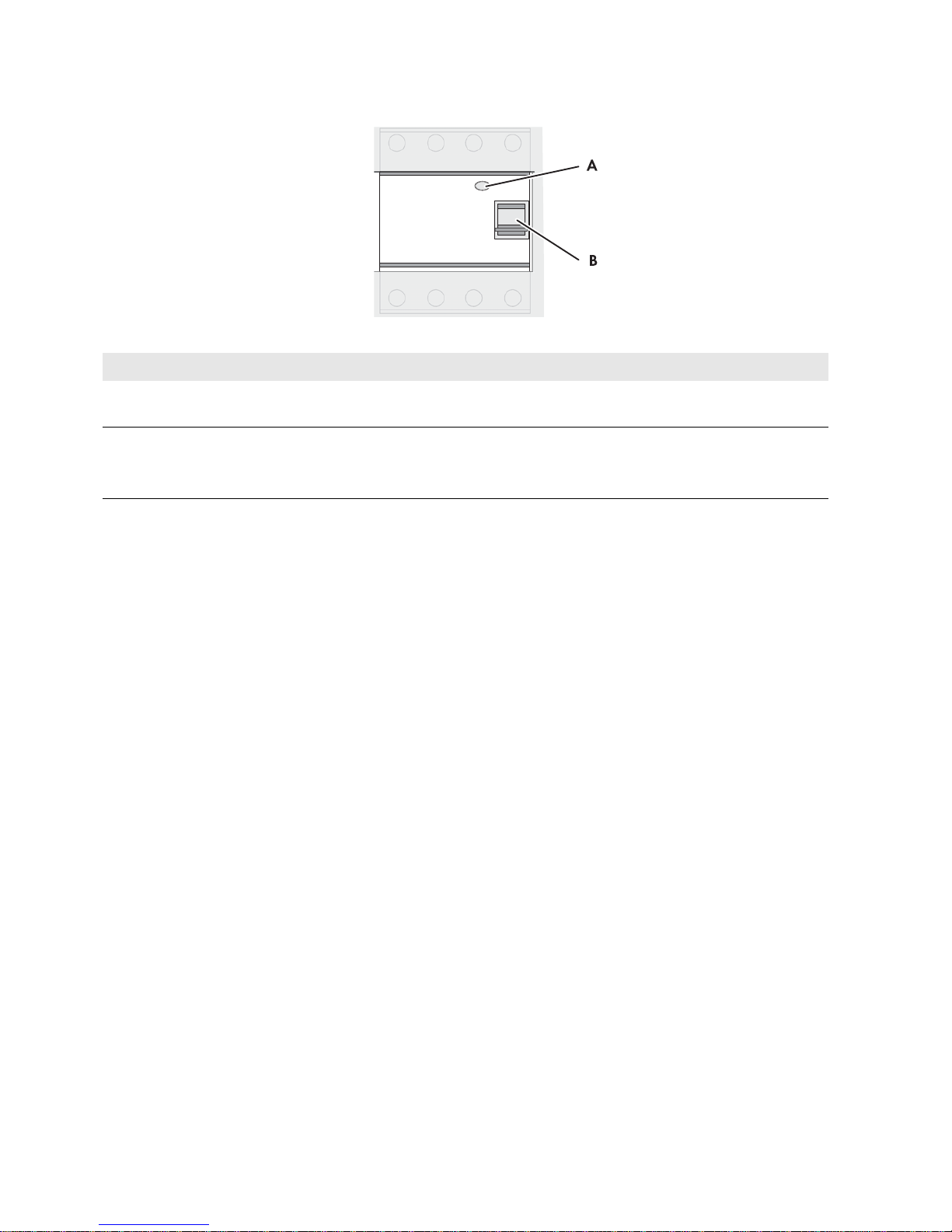
Figure4: Overview of the residual-current device
Position Designation Explanation
A Test button The functionality of the residual-current device must be tested
regularly (see Section10.1, page28).
B Switch lever Top position:
ON - residual-current device is switched on.
Bottom position: OFF - residual-current device has tripped or
is switched off.
 Loading...