


Micro Tuner model S-03
1998 – 2002 Dodge Ram
5,
9L 24 Valves Cummins Diesel Engine
Instruction Manual
PLEASE READ THIS ENTIRE INSTRUCTION MANUAL BEFORE PROCEEDING
Re
v. 1.24B
Page 1 of 20

THIS IS A HIGH PERFORMANCE PRODUCT USE AT YOUR OWN RISK
This product is intended for OFF ROAD USE ONLY
This product is not intended to be used to break the law
Do not use this product until you have read the following agreement.
This agreement sets forth the terms and conditions for the use of this product.
The installation of this product indicates that the buyer has read and understands this agreement and accepts the
terms and conditions.
DISCLAIMER OF LIABILITY
Smarty Performance King, its distributors, jobbers and dealers ( hereafter Seller ) shall be in no way responsible for the
product’s proper uses and service. THE BUYER HEREBY WAIVES ALL LIABILITY CLAIMS.
The buyer acknowledges that he is not relying on the Sellers skill or judgement to select of furnish goods suitable for any
particular purpose and that there are no liabilities which extend beyond the description on the face hereof, and the buyer
hereby waivers all remedies or liabilities expressed or implied, arising by law or otherwise ( including without any
obligation of the seller with respect fitness, merchantability and consequential damages ) whatever or not occasioned by
the sellers negligence.
The Seller disclaims any warranty and expressly disclaims any liability for personal injury and damages. The
buyer acknowledges and agrees that the disclaimer of any liability for personal injury is a material term for this
agreement and the buyer agrees to indemnify the Seller and to hold the Seller harmless from any claim related
to the item of the equipment purchased. Under no circumstances will the seller be liable for any damages or
expenses by reason of use or sale of any such equipment.
The Seller assumes no liability regarding the improper installation or misapplication of its products.
It is the installer's responsibility to check for proper installation and in doubt contact the manufacturer.
The buyer is solely responsible for all warranty issues from the manufacturer.
LIMITATION OF WARRANTY
Smarty Performance King ( Hereafter Seller ) gives Limited Warranty as to description, quality, merchantability, and
fitness for any particular purpose, productiveness, or any other matter of the Seller’s product sold herewith. The Seller
shall be in no way responsible for the products proper use and service and the buyer hereby waives all rights other than
those expressly written herein. This warranty shall not be extended, altered or varied except to be a written instrument
signed by Seller and Buyer.
The warranty is limited to one ( 1 ) year from the date of sale and limited solely to the parts contained within the products
kit. All products that are in question of warranty must be returned prepaid to the Seller and must be accompanied by a
dated proof of purchase receipt. All Warranty claims are subject to approval by Smarty Performance King.
Under no circumstances will the Seller be liable for any labor charged or travel time incurred by in
diagnosis for defects, removal, or reinstallation of this product or any other contingent expenses.
Under no circumstances will the Seller be liable for any damage or expenses incurred by reason of the use or sale of any
such equipment.
In the event that the buyer does not agree with this agreement: THE BUYER MAY PROMPTLY RETURN THIS
PRODUCT, IN A NEW AND UNUSED CONDITION, WITH A DATED PROOF OF PURCHASE TO THE PLACE OF
PURCHASE WITHIN TEN (10) DAYS FROM THE DATE OF PURCHASE FOR A FULL REFUND.
THE INSTALLATION OF THIS PRODUCT INDICATES THAT THE BUYER HAS READ AND
UN
DERSTANDS THIS AGREEMENT AND ACCEPTS THE TERMS AND CONDITIONS.
Page 2 of 20

CAUTION
This Smarty Performance King product is intended for use on unmodified stock engines. Remove any
performance enhancing electronic devices and make sure the ECM has been returned to STOCK if
you have used another manufacturer’s programmer before the Smarty Micro Tuner.
The use to change the performance characteristics of your vehicle could invalidate the warranty
provided by the vehicle manufacturer. Consult your vehicle warranty before using the product on
your vehicle.
NEVER CONNECT BOTH THE SMARTY CONNECTORS AT THE SAME TIME!
This could damage Smarty and the computer USB port.
It is recommended that you not store your Smarty Micro Tuner in your vehicle if ambient
temperatures in your area fall below 32°F. Excessively low temperatures can cause malfunction or
damage to Smarty Micro Tuner that is not covered by the Smarty Performance King warranty.
In the case of ECM replacement, restore the ECM back to the STOCK software before the ECM
replacement. Smarty works only with one vehicle and one ECM at a time while it is VIN Locked.
Under no circumstances we will refund, repair, or warranty units that are send in and result VIN #
locked.
RESTORE ECM TO STOCK SOFTWARE BEFORE ANY SERVICE ASSISTANCE.
If you need to return your vehicle to a service center, restore the vehicle ECM updating to STOCK
software following the instruction described below. The service center might reprogram your vehicle
with an updated STOCK software without your knowledge. If your vehicle has not been returned to
its STOCK software prior service, the Smarty Micro Tuner will no longer be able to program your
vehicle. Such failure is not covered by the Smarty Performance King warranty.
Under no circumstances will we refund, repair, or warranty units that are send in and result VIN #
locked.
Page 3 of 20

Index
1.Before You Begin.............................................................................................................................5
Your vehicle’s STOCK program...................................................................................................5
Service Centers................................................................................................................................5
Vehicle preparation.........................................................................................................................5
Smarty preparation.........................................................................................................................5
2.Smarty Overview.............................................................................................................................5
Keyboard operation........................................................................................................................5
Connectors.......................................................................................................................................5
3.Connecting Smarty to your vehicle................................................................................................6
4.Updating the ECM..........................................................................................................................6
First time update.............................................................................................................................6
Other updating................................................................................................................................7
Recovery of the ECM .....................................................................................................................9
5.Adjusting optional parameters.....................................................................................................11
Speed limiter..................................................................................................................................11
Torque............................................................................................................................................11
Injection Timing............................................................................................................................11
Injection Duration.........................................................................................................................11
6.Reading DTC’s...............................................................................................................................11
Reading Diagnostic Trouble Codes.............................................................................................11
Clearing DTC codes......................................................................................................................12
7.ABS Update....................................................................................................................................12
Tire height update.........................................................................................................................12
8.Appendix A: Error messages description....................................................................................14
9.Appendix B: DTC codes Interpretation......................................................................................15
Regarding DTC Interpretation....................................................................................................15
DTC Interpretation listing...........................................................................................................16
10.Warranty......................................................................................................................................20
11.Declaration of Conformity..........................................................................................................20
Page 4 of 20

1. Before You Begin
Your vehicle’s STOCK program
Your vehicle ECM must contain the manufacturer’s STOCK factory program. If you have used a
programmer from another aftermarket company you must use their product to return your ECM back
to STOCK condition before proceeding. If you have a performance-enhancing device installed, it must
be removed.
Service Centers
If you need to return your vehicle to a service center, restore the vehicle ECM updating to STOCK
software following the instruction described below. The service center might reprogram your vehicle
with an updated STOCK software without your knowledge. If your vehicle has not been returned to
its STOCK software prior service, the Smarty Micro Tuner will no longer be able to program your
vehicle. Such failure is not covered by the Smarty Performance King warranty.
Under no circumstances will we refund, repair, or warranty units that are send in and result VIN #
locked
Vehicle preparation
Before connecting the Smarty Micro Tuner to your vehicle, make sure that all power-draining
acc
essories are turned off: Radio, headlights, lights, cell phones, etc. All those devices need to be
turned off. Please apply the parking brake before you begin a download.
As the Smarty Micro Tuner needs full battery voltage to program, ensure your vehicle battery is fully
charged and NOT connected to a battery charger.
Do not disturb or remove the connection cable during the updating operation.
Smarty preparation
During the first use, Smarty reads and stores the identification parameters of your vehicle. After the
first use Smarty becomes “ VIN # locked “ and can be used only with your vehicle.
Returning your vehicle to STOCK software restores Smarty into the original, unlocked condition.
2. Smarty Overview
Keyboard operation
Smarty’s keyboard is composed of 12 keys:
• Nume
rical keys from 0 to 9, used to select menu options and enter numerical values
• Right arrow key, used to confirm the selected operation
• Left arrow key, used to go one step back in the operation flow
Connectors
Two connectors are available in Smarty’s upper side:
•
USB: used to connect a personal computer for updates to Smarty’s database. USB cable is not included.
Standard USB 1.1 or USB 2.0 cables can be used to connect Smarty to your personal computer.
• 15 pin connector for the OBD II cable; used to connect the vehicle through the diagnostic
connector placed below the driving wheel.
Page 5 of 20

The OBD II – J1926 diagnostic connector cable is included in Smarty’s box. Connecting other
cables to the cannon 15 pin connector invalidate Smarty Performance King warranty, because it
could damage Smarty.
Smarty automatically switches on when connecting one of the 2 above described connectors.
NEVER CONNECT BOTH THE CONNECTORS IN THE SAME MOMENT. This could damage
Smarty and the computer USB port. Such failure is not covered by the Smarty Performance king
warranty
3. Connecting Smarty to your vehicle
Turn on the ignition key. DO NOT START THE ENGINE.
Plug the dedicated cable to the 15 pin connector in the top side of Smarty and block the security
screws by hand.
Plug the Smarty cable into the diagnostic connector of your vehicle.
4. Updating the ECM
First time update
Turn on the ignition key. DO NOT START THE ENGINE.
Pl
ug the Smarty cable into the diagnostic connector of your vehicle. Smarty will display:
The second line of the display shows the firmware version and the tuning data version.
Both the internal firmware and the tuning data information can be updated connecting a personal
computer. See Smarty Performance King internet site for more details. Then main menu appears:
From the main menu, press ‘1’ to select ECM Update.
Press the ‘1’ key to select ECM Update.
Then the Options menu appears:
From the Options menu, press '1' to select Connect Truck.
Smarty will try to communicate with the ECM. If the connection cannot be established, Smarty asks
you to switch off the ignition key:
Pressing the ‘>’ key, Smarty asks to switch on the ignition key to retry the connection:
When the connection has been established, Smarty shows the current installed software. During the
first updating, the following page will appear:
The first time you update the ECM of your vehicle, Smarty reads the serial number of your vehicle,
the serial number of your ECM, and stores them into its onboard memory for future use. From this
moment on, Smarty will work only with your vehicle until it’s restored back to the stock settings.
Returning to STOCK software, Smarty restores itself to the original, unlocked condition.
Page 6 of 20

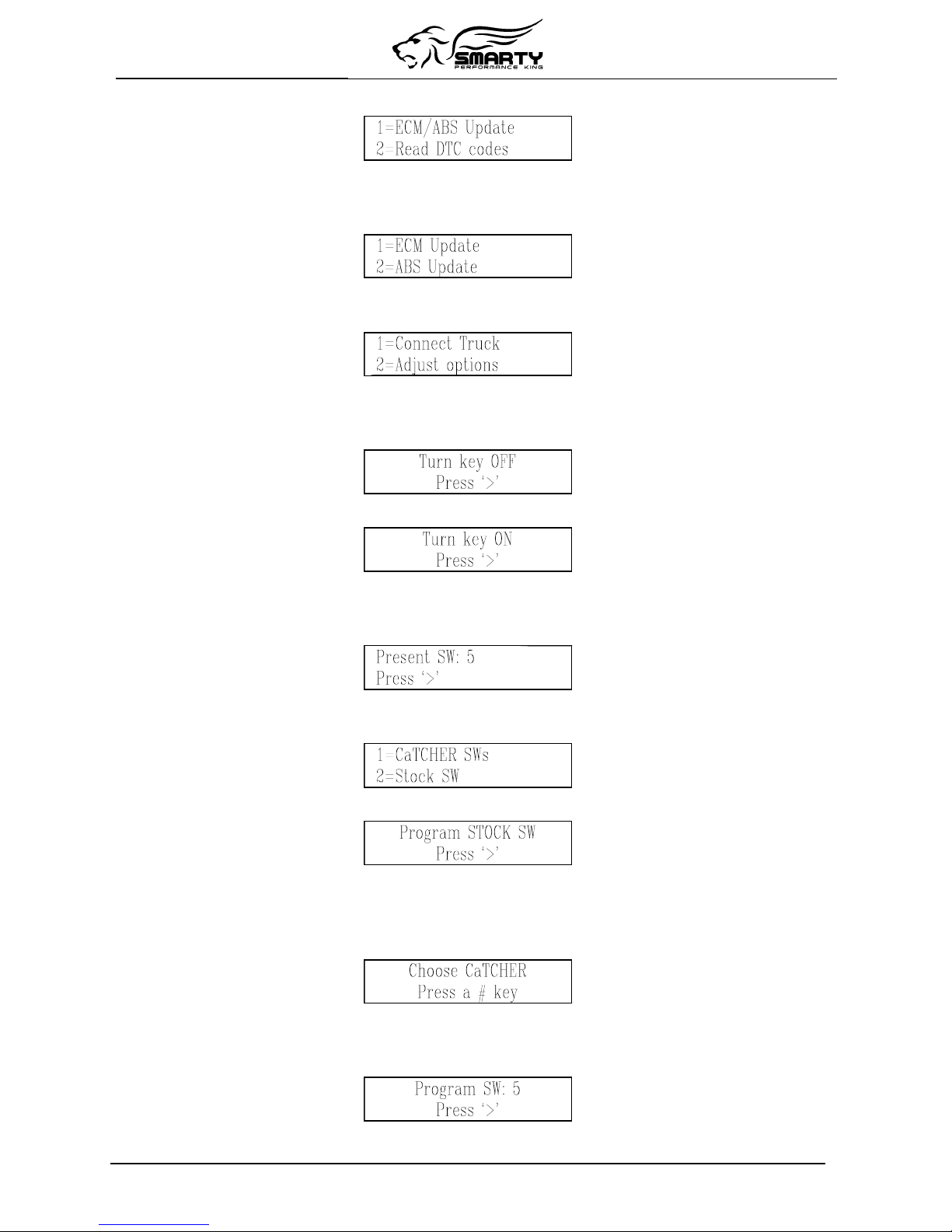
When the ‘>’ key has been pressed, Smarty asks you to select one of the CaTCHER softwares to be
load into the ECM:
You can choose among TEN different CaTCHER softwares according to the requested performance.
Any key, from 0 to 9, can be pressed.
Smarty asks you to confirm the selection before he downloads the new software into the ECM:
You can return back one step, in any moment with the ‘<’ key.
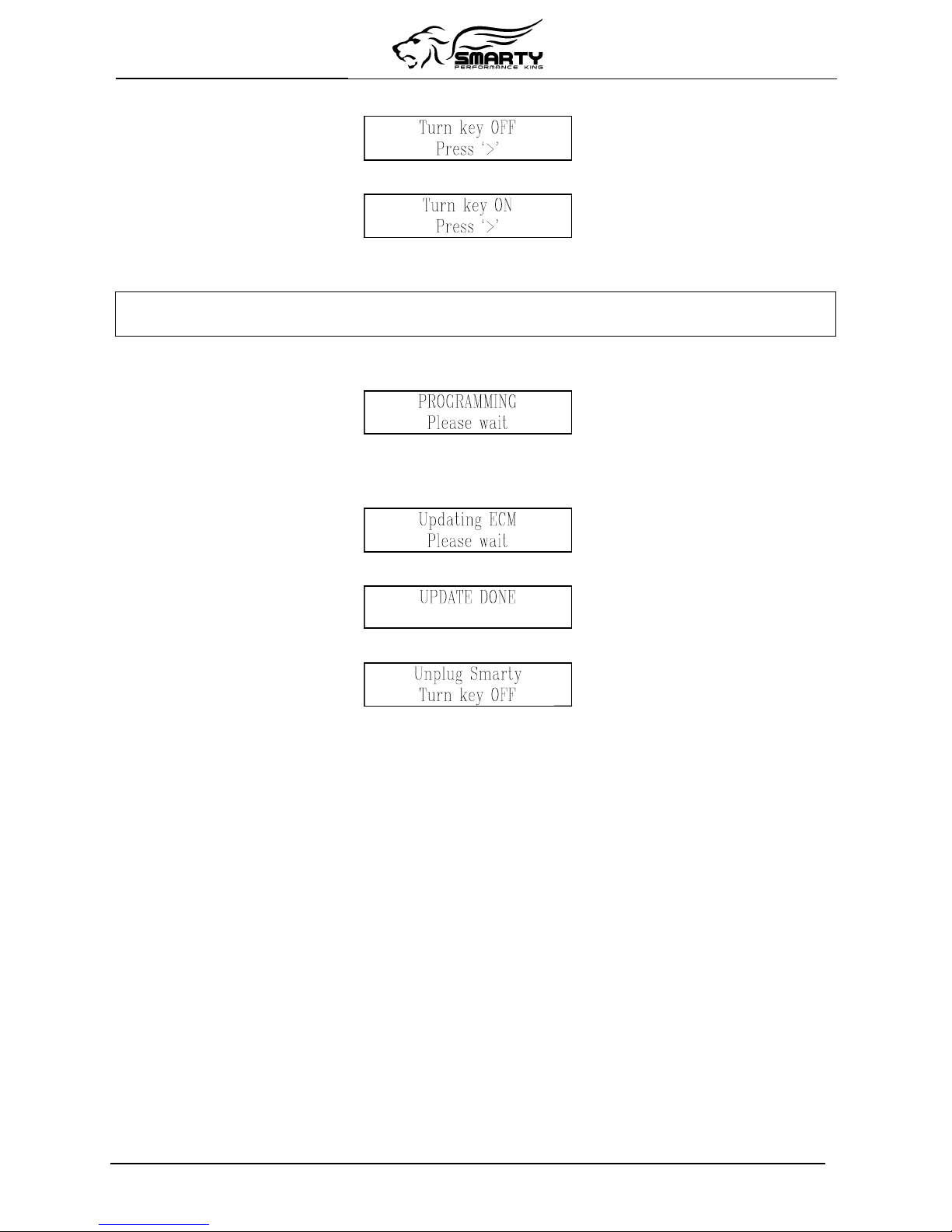
Pressing ‘>’ (or if the key ‘2’ has been pressed in the previous menu) the updating session starts. You
will see the following page:
After a few seconds, an up-counter with the percentage of the transmitted software will appear.
At the end of transmission (when 100% is reached) Smarty will update the functional parameters of
the ECM. A typical download time is two minutes.
The following page will appear:
At the end of the updating session, the following page appears:
After a few seconds Smarty displays the following page:
Please, unplug Smarty from the diagnostic port and turn the Key of for 30 seconds.
Remember to restore the STOCK software before returning your vehicle to a service center.
The service center might reprogram your vehicle with an updated STOCK software without your
knowledge. If your vehicle has not been returned to its STOCK software prior service, Smarty will no
longer be able to program your vehicle. Such failure is not covered by the Smarty Performance King
warranty. Under no circumstances will we refund, repair, or warranty units that are send in and
result VIN # locked.
Other updating
Once you have loaded a CaTCHER software in the ECM of your vehicle, Smarty is VIN Locked.
This means that Smarty will work only in your vehicle.
(Returning the ECM to STOCK software, Smarty restores itself to the original, unlocked condition.)
Turn on the ignition key. DO NOT START THE ENGINE. Plug Smarty’s cable into the diagnostic
connector of your vehicle and Smarty will display:
When the “ # “ symbols are displayed on the first line, Smarty is VIN# locked to a vehicle.
The second line of the display shows the firmware version and the tuning data version.
Both the internal firmware and the tuning data information can be updated connecting a personal
computer when updates become available. See Updating Smarty chapter for more details.
Page 7 of 20
After a few seconds the main menu will appear:
Once Smarty is VIN# Locked, the ABS control system can be accessed in order to correct the wheel
height.
Pressing the ‘1’ key, a second menu appears:
Press ‘1’ to select ECM Update.
Then the Options menu appears:
From the Options menu, press '1' to select Connect Truck.
Smarty will try to communicate with the ECM. If the connection cannot be established, Smarty asks
you to switch off the ignition key:
Pressing the ‘>’ key, Smarty asks to switch on the ignition key to retry the connection:
When the connection has been established, Smarty shows the currently installed software.
After the first update, the following page will appear displaying the CaTCHER software currently
installed in the ECM:
When the ‘>’ key has been pressed, Smarty asks for the selection between the STOCK and the
CaTCHER software:
Pressing the ‘2’ key, Smarty asks for the confirmation of the operation of restore:
Pressing the ‘>’ key, the ECM is restored to STOCK and Smarty returns to original, unlocked
condition, so it can be used with another vehicle.
Pressing the ‘1’ key in the above described menu, Smarty asks for the selection of the CaTCHER
software to be loaded into the ECM:
You can choose among 10 different CaTCHER softwares according to the requested performance.
Any key, from 0 to 9, can be pressed.
Smarty asks you to confirm the selection before he downloads the new software into the ECM:
You can return back one step, in any moment with the ‘<’ key.
Page 8 of 20

Pressing ‘>’ (or if the key ‘2’ has been pressed in the previous menu) the updating session starts. You
will see the following page:
After a few seconds, an up-counter with the percentage of transmitted software will appear.
At the end of transmission (when the 100% is reached) Smarty will update the functional parameters
of the ECM. The following page will appear:
At the end of the updating session, the following page appears:
After a few seconds Smarty displays the following page:
Please, unplug Smarty from the diagnostic port and turn the Key of for 30 seconds.
Recovery of the ECM
If an interruption occurs during an Update or the Update operation is terminated before the normal end
for any reason the ECM will not be operational. You must recover the ECM using Smarty to resume
the update process.
Attention! The engine will not start before the ECM has been recovered properly!
( The Wait to Start Light will flash continuously )
DON’T PANIC!
Smarty Performance King has developed a special boot loader software that is used during all the
ECM Updates. Unlike the OEM DRBIII tool, there’s no need to pull fuses or unplug the batteries! No
tools needed! At Smarty Performance King we’ve done our homework!
Just follow the directions on Smarty’s display.
Smarty will handle the situation for you in a few simple steps.
Unplug Smarty, then plug it in again. After a few seconds the usual main menu will appear.
Pressing the ‘1’ key, the second menu appears:
Press ‘1’ to select ECM Update.
Then the Options menu appears:
From the Options menu, press '1' to select Connect Truck.
Smarty will try to establish the communication with the ECM. The connection cannot be established
because the last updating session has been interrupted. Smarty knows that the last update has not been
performed correctly thus he’s able to recognise the not operational ECM condition.
Page 9 of 20
Smarty asks you to turn OFF the ignition key:
Pressing the ‘>’ key, Smarty asks you then to turn ON the ignition key to retry the communication:
Press the ‘>’ key.
The communication cannot start yet. Smarty shows the following message:
A previous update has been interrupted
Press ‘>’ to restore ECM to Stock
The message is longer than the physical display, so it rotates continuously.
Pressing ‘>’ the recovery operation starts. You will see the following page:
After a few seconds, an up-counter with the percentage of the transmitted software will appear.
At the end of the transmission (when the 100% is reached) Smarty will update the functional
parameters of the ECM. The following page will appear:
At the end of the recovery operation, the following page appears:
After a few seconds Smarty displays the following page:
The job is done. The ECM has been returned to the STOCK condition and Smarty is no longer VIN#
Locked. You’re ready to start from the beginning again.
Page 10 of 20

5. Adjusting optional parameters
Before the programming, Smarty proposes the adjustment of the optional parameters.
To enter this function, press 2 in the Options menu:
The list of optional parameter varies according to the installed software.
For each parameter, the current option status is shown on the first line of the display. With Smarty
numeric keyboard, the optional parameters can be adjusted.
To maintain unchanged the current parameter, press the '>' key.
You can return back one step, in any moment with the ‘<’ key.
Speed limiter
The speed limiter can be adjusted anywhere from 25 to 250 MPH in one MPH steps.
NO
TE: only 2001 and 2002 trucks the speed limit value is the real MPH speed. In older trucks, the
speed limit is only a speed factor that compensate the maximum speed.
IMPORTANT NOTICE
Your tires might not be rated for increased speeds. Please check your tires rating!
To set the speed limiter to Stock, select 0.
Torque
The Torque selection can be programmed with a value between 1 (stock) and 6 (high). To use the
default torque setting for the current CaTCHER level, press 0.
Injection Timing
The Timing selection can be programmed 1 (stock), 2 (advanced), 3 (moderate) or 4 (greatest). To use
the default timing setting for the current CaTCHER level, press 0.
Injection Duration
The Duration selection can be programmed with a value between 1 (stock) and 5 (high). To use the
default duration setting for the current CaTCHER level, press 0.
6. Reading DTC’s
Reading Diagnostic Trouble Codes
From the main menu, press the ‘2’ key to select this function.
Smarty will try to establish the communication with the ECM.
If the Key was not turned into the on position Smarty will display this message:
Page 11 of 20

Pressing the ‘>’ key, Smarty asks you to turn on the ignition key to retry the connection:
When the connection has been established, if no DTC codes are present, the following page appears:
If one or more DTC’s are stored, Smarty shows the number of DTC’s present with the following page:
With the keys ‘<’ and ‘>’ all the present DTC codes can be displayed, one code at a time with the
following page:
The first line of display shows the DTC “P” code. The second line shows the DTC code description.
If the DTC code description is longer that the physical dimension of the display, the description
rotates continuously.
Some DTC codes could have no description. In that case, the message “See documentat.” Appears.
See appendix B of this manual for a complete listing of the DTC codes.
Clearing DTC codes
At the end of the visualisation of the last DTC code present, Smarty propose to clear all the stored
DTC codes from the ECM memory:
Pressing the ‘1’ key, all the DTC codes stored in the ECM memory are erased.
Pressing the ‘2‘ key, the DTC’s will not be erased.
When the erasing operation has been completed, the following page appears:
7. ABS Update
Tire height update
Once Smarty is VIN# Locked (i.e. a CaTCHER software has been loaded in the ECM) the
speedometer of the vehicle can be adjusted according to the tire height.
To update the tire height you have to choose the ABS update function in the main menu:
Pressing the ‘1’ key, the second menu appears:
Pressing the ‘2’ key, Smarty will try to establish the communication with the ABS.
If the Key was not turned into the on position Smarty will display this message:
Page 12 of 20

Pressing the ‘>’ key, Smarty asks you to turn on the ignition key to retry the connection:
When the connection has been established, Smarty shows the current tire height with the following
page:
You can type in the correct tire height with the numerical keys.
Any tire height from 25.00” to 45.00” can be chosen in 0.25” increments.
As usual, with the ‘<’ key, Smarty returns back one step, so you can eventually correct the input
datum.
When you have inserted the correct tire height, Smarty asks the confirmation to proceed with the ABS
programming with the following page:
With the ‘<’ key, Smarty returns back one step, so you can eventually correct the input.
Pressing ‘>’ key, Smarty updates the ABS unit with the new tire height.
A typical ABS programming takes not more than a couple seconds.
When the operation has been successfully completed, the following page appears:
Hint: it seems that the programming of the ABS units cannot always be performed. We have found
quiet often that the ABS sends the positive response for the new programming but in reality it didn’t
execute it. For this reason, Smarty shows the current tire height after the programming too. So you
can verify the operation and, eventually, try again. Smarty already tries to take care of that problem
by programming up to three times the ABS with the requested value. If the ABS still does not take
the programming after those attempts, please try again.
For this reason Smarty requests the current tire height again from the ABS unit and the following page
is shown:
If the ‘<’ key is pressed, the ABS update function can be repeated.
Pressing the ‘>’ key, the following page is shown:
Hint: How accurate is the ABS? During our testing we have often found that it is not very accurate.
On our personal test truck with 33” tires we need to set the ABS to 32” for accurate Speed and
odometer readings. Please check with a GPS.
Page 13 of 20

8. Appendix A: Error messages description
This section contains all the possible error messages shown by Smarty:
Error message Cause Solution
CCD ERROR # The communication with
ABS unit doesn’t work
Check connection cable or check ABS
unit
COMM. TIME OUT The ECM of the vehicle
doesn’t answer to Smarty
Turn the ignition key on (DO NOT
START ENGINE) or Check the
connection cable
ECM Changed The ECM unit of the vehicle
has been changed
Restore the original ECM back to
STOCK before changing ECM
Empty Memory,
Please Update
The last Update operation
(through USB port) has been
unsuccessfully completed.
Smarty memory has been
corrupted.
Repeat the Update operation.
The data files are available on the
Smarty Performance King internet site.
INTERNAL ERROR # Smarty internal malfunction Call Smarty Performance king
assistance
Memory Error A malfunction in the
Smarty’s memory
Call Smarty Performance King
assistance
Memory Written
Wrong Data File
The update file transmitted
to Smarty through USB port
is corrupted
Download again the update file from
Smarty Performance King internet site
and update Smarty with the correct file
PROGRAM ABORTED The ECM update function
has been interrupted
Restore the ECM to STOCK with the
recovery procedure.
S/N Verify Error The serial number of your
vehicle has not been verified
Check connection cable
SW Version doesn’t
Match S/N
The ECM software version
doesn’t match with the serial
number
Please contact Smarty Performance
King or the seller.
UNKNOWN SOFTWARE Your vehicle contains a
software version unknown to
Smarty
Please contact Smarty Performance
King or the seller.
VIN# Locked Smarty has been connected
to a different vehicle
Restore the original vehicle back to
STOCK before connecting Smarty to a
new vehicle
WRONG COMMUNIC. The communication between
Smarty and the ECM unit is
disturbed
Check the connection cable or the
battery charge level
WRONG VIN# The serial number of your
vehicle is not valid
Wait 30 seconds with the ignition key
on and try again
Page 14 of 20

9. Appendix B: DTC codes Interpretation
The DTC (Diagnostic Trouble Code) reader function present in Smarty Micro Tuner is for
convenience purpose only. Industry standard interpretation tables are supplied below. Smarty
Performance King makes no warranty of the correctness of the interpretations.
Regarding DTC Interpretation
SAE Code Sections:
• P00xx Fuel & Air metering, Auxiliary emission controls
• P01xx Fuel & Air metering
• P02xx Fuel & Air metering
• P03xx Ignition & Firing systems
• P04xx Auxiliary emission controls
• P05xx Vehicle speed, Idle control & Auxiliary inputs
• P06xx Computer & Auxiliary outputs
• P07xx Transmission
• P08xx Transmission
• P09xx Transmission
Manufacturer Code Sections:
• P10xx Fuel & Air metering, Auxiliary emission controls
• P11xx Fuel & Air metering
• P12xx Fuel & Air metering
• P13xx Ignition & Firing systems
• P14xx Auxiliary emission controls
• P15xx Vehicle speed, Idle control & Auxiliary inputs
• P16xx Computer & Auxiliary outputs
• P17xx Transmission
• P18xx Transmission
• P19xx Transmission
Many logged codes are transitory, they are automatically reset.
DTC P1000 is an indication that the vehicle needs to be driven for a period so that the vehicle can
learn certain operating characteristics and it will reset automatically. This code cannot be cleared
externally.
Page 15 of 20

DTC Interpretation listing
P0016–CRANKSHAFT / CAMSHAFT TIMING MISALIGNMENT
P0030-1/1 02 SENSOR HEATER RELAY MALFUNCTION
P0036-1/1 02 SENSOR HEATER RELAY MALFUNCTION
P0071-AMBIENT AIR TEMPERATURE SENSOR
PERFORMANCE
P0072-AMBIENT AIR TEMPERATURE SENSOR CIRCUIT LOW
P0088-FUEL RAIL PRESSURE SIGNAL IS ABOVE MAX LIMIT
P0101-MAF SENSOR PERFORMANCE
P0102-MAF SENSOR LOW FREQUENCY
P0103-MAF SENSOR HIGH FREQUENCY
P0106-BAROMETRIC PRESSURE OUT OF RANGE
P0107-MAP SENSOR VOLTAGE TOO LOW
P0108–MAP SENSOR VOLTAGE TOO HIGH
P0111-INTAKE AIR TEMP PERFORMANCE
P0112-INTAKE AIR TEMP SENSOR VOLTAGE TOO LOW
P0113-INTAKE AIR TEMP SENSOR VOLTAGE TOO HIGH
P0116–ENGINE COOLANT TEMPERATURE SENSOR CIRCUIT
PERFORMANCE
P0117-ENGINE COOLANT TEMPERATURE (ECT) SENSOR
VOLTAGE TOO LOW
P0118-ENGINE COOLANT TEMPERATURE (ECT) SENSOR
VOLTAGE TOO HIGH
P0121-TP SENSOR VOLTAGE DOES NOT AGREE WITH MAP
P0122-THROTTLE POSITION SENSOR VOLTAGE TOO LOW
P0123-THROTTLE POSITION SENSOR VOLTAGE TOO HIGH
P0125-INSUFFICIENT COOLANT TEMP FOR CLOSED-LOOP
FUEL CONTROL
P0128-THERMOSTAT RATIONALITY
P0130-1/1 02 SENSOR HEATER RELAY MALFUNCTION
P0131-O2 SENSOR 1/1 CIRCUIT VOLTAGE TOO LOW
P0132-O2 SENSOR 1/1 CIRCUIT VOLTAGE TOO HIGH
P0133-O2 SENSOR 1/1 SLOW RESPONSE
P0134-02 SENDOR 1/1 STAYS AT CENTER
P0135-O2 SENSOR 1/1 HEATER PERFORMANCE
P0136-O2 SENSOR 1/2 HEATER CIRCUIT MALFUNCTION
P0137-O2 SENSOR 1/2 CIRCUIT LOW
P0138-O2 SENSOR 1/2 CIRCUIT HIGH
P0139-O2 SENSOR 1/2 SLOW RESPONSE
P0140-02 SENSOR 1/2 STAYS AT CENTER
P0141-02 SENSOR 1/2 RELAY
P0143-02 SENSOR 1/3 SHORTED TO GROUND
P0144-02 SENSOR 1/3 SHORTED TO VOLTAGE
P0145-02 SENSOR 1/3 SLOW RESPONSE
P0146-02 SENSOR 1/3 STAYS AT CENTER
P0147-02 SENSOR 1/3 HEATER FAILURE
P0148-FUEL DELIVERY ERROR
P0151-O2 SENSOR 2/1 CIRCUIT LOW
P0152-O2 SENSOR 2/1 CIRCUIT HIGH
P0153-O2 SENSOR 2/1 SLOW RESPONSE
P0154-O2 SENSOR 2/1 STAYS AT CENTER
P0155-O2 SENSOR 2/1 HEATER PERFORMANCE
P0157-O2 SENSOR 2/2 CIRCUIT VOLTAGE TOO LOW
P0158-O2 SENSOR 2/2 CIRCUIT VOLTAGE TOO HIGH
P0159-O2 SENSOR 2/2 SLOW RESPONSE
P0160-O2 SENSOR 2/2 STAYS AT CENTER
P0161-O2 SENSOR 2/2 HEATER PERFORMANCE
P0168-DECREASED ENGINE PERFORMANCE DUE TO HIGH
INJECTION PUMP FUEL TEMPERATURE
P0169-WATER IN FUEL (WIF) LIGHT ON TOO LONG
P0171-FUEL SYSTEM 1/1 LEAN
P0172-FUEL SYSTEM 1/1 RICH
P0174-FUEL SYSTEM 2/1 LEAN
P0175-FUEL SYSTEM 2/1 RICH
P0176-LOSS OF FLEX FUEL CALIBRATION SIGNAL
P0177-WATER IN FUEL
P0178-WATER IN FUEL SENSOR VOLTAGE TOO LOW
P0178-FLEX FUEL SENSOR VOLTAGE TOO LOW
P0180-CNG TEMP SENSOR VOLTAGE FAIL
P0181-FUEL PUMP INJECTION PUMP FAILURE
P0182-CNG TEMP SENSOR VOLTAGE TOO LOW
P0183-CNG TEMP SENSOR VOLTAGE TOO HIGH
P0192-FUEL RAIL PRESSURE SENSOR VOLTAGE TOO LOW
P0193-FUEL RAIL PRESSURE SENSOR VOLTAGE TOO HIGH
P0201-INJECTOR #1 CONTROL CIRCUIT
P0202-INJECTOR #2 CONTROL CIRCUIT
P0203-INJECTOR #3 CONTROL CIRCUIT
P0204-INJECTOR #4 CONTROL CIRCUIT
P0205-INJECTOR #5 CONTROL CIRCUIT
P0206-INJECTOR #6 CONTROL CIRCUIT
P0207-FUEL INJECTOR 7 CIRCUIT
P0208-FUEL INJECTOR 8 CIRCUIT
P0209-FUEL INJECTOR 9 CIRCUIT
P0210-FUEL INJECTOR 10 CIRCUIT
P0215-FUEL INJECTOR PUMP CONTROL CIRCUIT
P0216-FUEL INJECTOR PUMP TIMING FAILURE
P0217-DECREASED ENGINE PERFORMANCE DUE TO ENGINE
OVERHEAT CONDITION
P0219-CRANKSHAFT POSITION SENSOR OVER SPEED
SIGNAL
P0220-APP SENSOR 2 CIRCUIT
P0221-APP SENSOR 2 PERFORMANCE
P0222-APP SENSOR 2 CIRCUIT LOW
P0222-IDLE VALIDATION SIGNALS BOTH LOW
P0223-INJECTION PULSE WIDTH ERROR (RISE TIME LONG)
P0223-IDLE VALIDATION SIGNALS BOTH HIGH (ABOVE 5V)
P0225-APP SENSOR 3 CIRCUIT
P0226-APP SENSOR 3 CIRCUIT PERFORMANCE
P0227-APP SENSOR 2 CIRCUIT LOW VOLTAGE
P0228-APP SENSOR 2 CIRCUIT HIGH VOLTAGE
P0230-TRANSFER PUMP (LIFT PUMP) CIRCUIT OUT OF
RANGE
P0231-FUEL PUMP FEEDBACK CIRCUIT LOW VOLTAGE
P0232-FUEL SHUT-OFF SIGNAL VOLTAGE TOO HIGH
P0234-TURBOCHARGER OVERBOOST CONDITION
P0236-MAP SENSOR TOO HIGH TOO LONG
P0237-MAP SENSOR VOLTAGE TOO LOW
P0238-MAP SENSOR VOLTAGE TOO HIGH
P0243-OPEN OR SHORTED CONDITION DETECTED IN THE
TURBOCHARGER WASTEGATE SOLENOID CONTROL
P0251-FUEL INJECTION PUMP FUEL VALVE FEEDBACK
CIRCUIT
P0252-FUEL INJECTION PUMP FUEL VALVE STUCK
P0253-FUEL INJECTION PUMP FUEL VALVE OPEN CIRCUIT
P0254-FUEL INJECTION PUMP FUEL VALVE CURRENT TOO
HIGH
P0263-CYLINDER 1 BALANCE SYSTEM
P0266-CYLINDER 2 BALANCE SYSTEM
P0269-CYLINDER 3 BALANCE SYSTEM
P0272-CYLINDER 4 BALANCE SYSTEM
P0275-CYLINDER 5 BALANCE SYSTEM
P0278-CYLINDER 6 BALANCE SYSTEM
P0281-CYLINDER 7 BALANCE SYSTEM
P0284-CYLINDER 8 BALANCE SYSTEM
P0300-MULTIPLE CYLINDER MISFIRE
P0301-CYLINDER # 1 MISFIRE
P0302-CYLINDER # 2 MISFIRE
P0303-CYLINDER # 3 MISFIRE
P0304-CYLINDER # 4 MISFIRE
P0305-CYLINDER # 5 MISFIRE
P0306-CYLINDER # 6 MISFIRE
P0307-CYLINDER #7 MISFIRE
P0308-CYLINDER #8 MISFIRE
P0309-CYLINDER #9 MISFIRE
P0310-CYLINDER #10 MISFIRE
P0320–NO CRANK REFERENCE SIGNAL AT PCM
P0325-KNOCK SENSOR 1 CIRCUIT .
P0327-KNOCK SENSOR NOISE CHANNEL LOW VOLTAGE
P0330-KNOCK SENSOR 2 CIRCUIT
P0335-CRANKSHAFT POSITION SENSOR CIRCUIT
P0336-CRANKSHAFT POSITION (CKP) SENSOR SIGNAL
P0337-CRANKSHAFT POSITION (CKP) SENSOR VOLTAGE
TOO LOW
P0338-CRANKSHAFT POSITION (CKP) SENSOR VOLTAGE
TOO HIGH
P0339-CRANKSHAFT POSITION SENSOR INTERMITTENT
P0340-CAMSHAFT POSITION (CMP) LOST
P0341-CAMSHAFT POSITION (CMP) SENSOR SIGNAL
P0342-ESS VOLTAGE SUPPLY LOW
P0343-ESS VOLTAGE SUPPLY HIGH
P0350-IGNITION COIL DRAWN TOO MUCH CURRENT
P0351-IGNITION COIL #1 PRIMARY CIRCUIT
P0352-IGNITION COIL #2 PRIMARY CIRCUIT
P0353-IGNITION COIL #3 PRIMARY CIRCUIT
P0354-IGNITION COIL #4 PRIMARY CIRCUIT
P0355-IGNITION COIL #5 PRIMARY CIRCUIT
P0356-IGNITION COIL #6 PRIMARY CIRCUIT
Page 16 of 20

P0357-IGNITION COIL #7 PRIMARY CIRCUIT
P0358-IGNITION COIL #8 PRIMARY CIRCUIT
P0370-FUEL INJECTION PUMP SPEED/POSITION SENSOR
SIGNAL LOST
P0380-INTAKE AIR HEATER RELAY NO.1 CONTROL CIRCUIT
P0380-GLOW PLUG CIRCUIT PERFORMANCE
P0381-WAIT TO START LAMP INOPERATIVE
P0382-INTAKE AIR HEATER RELAY NO.2 CONTROL CIRCUIT
P0387-CKP SENSOR SUPPLY VOLTAGE TOO LOW
P0388-CKP SENSOR SUPPLY VOLTAGE TOO HIGH
P0400-EXHAUST GAS RECIRCULATION (EGR) FLOW
MALFUNCTION
P0401-EGR SYSTEM PERFORMANCE
P0403-EGR SOLENOID CIRCUIT
P0404-EGR POSITION SENSOR RATIONALITY OPEN
P0405-EGR POSITION SENSOR CIRCUIT LOW
P0406-EGR POSITION SENSOR CIRCUIT HIGH
P0410-AIR SYSTEM
P0412-SECONDARY AIR SOLENOID CIRCUIT
P0420-1/1 CATALYTIC CONVERTER EFFICIENCY
P0430-1/2 CATALYTIC CONVERTER EFFICIENCY
P0432-1/2 CATALYTIC CONVERTER EFFICIENCY
P0440-GENERAL EVAP SYSTEM FAILURE
P0441-EVAP PURGE FLOW MONITOR
P0442-EVAP LEAK MONITOR MEDIUM (0.040) LEAK
DETECTED
P0443-EVAP PURGE SOLENOID CIRCUIT
P0446-EVAP EMISSION VENT VALVE PERFORMANCE
P0452-EVAP EMISSION PRESSURE SENSOR CIRCUIT LOW
VOLTAGE
P0453- EVAP EMISSION PRESSURE SENSOR CIRCUIT HIGH
VOLTAGE
P0455-EVAP LEAK MONITOR LARGE LEAK DETECTED
P0456-EVAP LEAK MONITOR SMALL (0.020) LEAK DETECTED
P0460-FUEL LEVEL SENDING UNIT NO CHANGE OVER MILES
P0461-FUEL LEVEL UNIT NO CHANGE OVER TIME
P0462-FUEL LEVEL SENDING UNIT VOLTS TOO LOW
P0463-HIGH VOLTAGE DETECTED AT THE FUEL LEVEL
SENSOR
P0475-EPR SOLENOID CIRCUIT
P0477-EXHAUST PRESSURE CONTROL RELAY LOW
P0478- EXHAUST PRESSURE CONTROL RELAY HIGH
P0480-COOLING FAN 1 CONTROL CIRCUIT OPEN (LOW
SPEED FAN)
P0483-FAN SPEED
P0500-NO VEHICLE SPEED SENSOR SIGNAL
P0501-VEHICLE SPEED SENSOR PERFORMANCE
P0505-IDLE AIR CONTROL MOTOR CIRCUITS
P0506-IDLE SPEED PERFORMANCE LOWER THAN EXCEPTED
P0507-IDLE SPEED PERFORMANCE HIGHER THAN
EXCEPTED
P0508-UNDERCURRENT CONDITION DETECTED IN LINEAR
IDLE AIR CONTROL MOTOR FEEDBACK SENSE
CIRCUIT
P0509-OVER CURRENT CONDITION DETECTED IN LINEAR
IDLE AIR CONTROL MOTOR FEEDBACK SENSE
CIRCUIT
P0514-BAT TEMPERATURE SENSOR RATIONALITY
P0516-BATTERY TEMPERATURE SENSOR CIRCUIT LOW
P0517-BATTERY TEMPERATURE SENSOR CIRCUIT HIGH
P0520-ENGINE OIL PRESSURE SENSOR CIRCUIT
P0521-ENGINE OIL PRESSURE SENSOR PERFORMANCE
P0522-OIL PRESSURE CIRCUIT LOW
P0523-OIL PRESSURE CIRCUIT HIGH
P0524-OIL PRESSURE TOO LOW
P0532-A/C PRESSURE SENSOR CIRCUIT LOW
P0533-A/C PRESSURE SENSOR CIRCUIT HIGH
P0541-LOW VOLTAGE ON THE #1 INTAKE AIR HEATER RELAY
P0542-HIGH VOLTAGE ON THE #1 INTAKE AIR HEATER RELAY
P0545-A/C CLUTCH RELAY CIRCUIT
P0551-POWER STEERING PRESSURE SWITCH FAILURE
P0560-SYSTEM VOLTAGE
P0562-CHARGING SYSTEM VOLTAGE TOO LOW
P0563- CHARGING SYSTEM VOLTAGE TOO LOW
P0567-CRUISE RESUME CIRCUIT
P0568-CRUISE SET CIRCUIT
P0571-CRUISE BRAKE SWITCH 1 PERFORMANCE
P0572-BRAKE SWITCH 1 LOW
P0573-BRAKE SWITCH 1 HIGH
P0575-CRUISE SWITCH FAILURE (SHORTED)
P0577-CRUISE SWITCH FAILURE (OPEN)
P0579-SPEED CONTROL SWITCH 1 PERFORMANCE (5.7L)
P0580-LOW VOLTAGE DETECTED AT THE SPEED CONTROL
MULTIPLEXED SWITCH
P0581-HIGH VOLTAGE DETECTED AT THE SPEED CONTROL
MULTIPLEXED SWITCH
P0600-PCM FAILURE SERIAL COMMUNICATION LINK
P0601-PCM INTERNAL CONTROLLER FAILURE
P0602-ECM FUELING CALIBRATION ERROR
P0603-VCM MEMORY RESET
P0604-ECM RAM CHECK FAILURE
P0605-ECM ROM CHECK FAILURE
P0606-ECM HARDWARE ERROR
P0607-ECU INTERNAL FAILURE
P0615-STARTER RELAY CONTROL CIRCUIT
P0621-GENRATOR L TERMINAL CIRCUIT
P0622-GENERATOR FIELD NOT SWITCHING PROPERLY
P0628-FUEL PUMP RELAY CICRUIT LOW
P0628-LOW VOLTAGE DETECTED AT THE FUEL LIFT PUMP
P0629-FUEL PUMP RELAY CICRUIT HIGH
P0629-HIGH VOLTAGE DETECTED AT THE FUEL LIFT PUMP
P0630-VIN NOT PROGRAMMED IN PCM
P0633-SKIM KEY NOT PROGRAMMED IN PCM
P0642-SENSOR REFERENCE VOLTAGE 1 CIRCUIT LOW
P0643- SENSOR REFERENCE VOLTAGE 1 CIRCUIT HIGH
P0645-A/C CLUTCH CONTROL CIRCUIT
P0646-LOW VOLTAGE DETECTED AT THE A/C CLUTCH RELAY
P0647-HIGH VOLTAGE DETECTED AT THE A/C CLUTCH
RELAY
P0650-MALFUNCTION INDICATOR LAMP (MIL) CIRCUIT
P0652-SENSOR REFERENCE VOLTAGE 2 CIRCUIT LOW
P0653-SENSOR REFERENCE VOLTAGE 2 CIRCUIT HIGH
P0654-ENGINE SPEED OUTPUT CIRCUIT
P0698-SENSOR REF VOLTAGE 3 CIRCUIT LOW
P0699- SENSOR REF VOLTAGE 3 CIRCUIT HIGH
P0700-EATX CONTROLLER DTC PRESENT
P0703-BRAKE SWITCH PERFORMANCE
P0704-CLUTCH SWITCH CIRCUIT (M/T)
P0711-TRANS TEMP SENSOR, NO TEMP RISE AFTER START
P0712-TRANS TEMP SENSOR TOO LOW
P0713-TRANS TEMP SENSOR TOO HIGH
P0720-LOW OUTPUT SPEED SENSOR RPM, ABOVE 15MPH
P0740-TORQUE CONVERTER CLUTCH, NO RPM DROP AT
LOCKUP
P0743-TORQUE CONVERTER CLUTCH SOLENOID/TRANS
RELAY CIRCUIT
P0748-GOVERNOR PRESSURE SOL CONTROL/TRANS RELAY
CIRCUIT
P0751-O/D SWITCH PRESSED (LOW) MORE THAN 5 MINUTES
P0753-TRANS 3-4 SHIFT SOL/TRANS RELAY CIRCUIT
P0756-AW4 SHIFT SOL B (2-3) FUNCTIONAL FAILURE
P0783-(3-4) SHIFT SOL, NO RPM DROP AT LOCKUP
P0801-REVERSE GEAR LOCKOUT CIRCUIT OPEN OR
SHORTED
P0830-CLUTCH DEPRESSED SWITCH CIRCUIT
P0833-CLUTCH RELEASED SWITCH CIRCUIT
P0837-4WD SWITCH PERFORMANCE
P0838-4WD SWITCH CIRCUIT LOW
P0839-4WD SWITCH CIRCUIT HIGH
P1000-IGNITION CIRCUIT LOW
P1001-IGNITION CIRCUIT HIGH
P1004-ECU BATTERY FEED & POWER GROUNDS
P1005-SYSTEM GROUND CIRCUIT
P1006-EGR/EVAP SOLENOID CIRCUIT LOW
P1007-EGR/EVAP SOLENOID CIRCUIT HIGH
P1008-POWER STEERING CIRCUIT LOW
P1009-POWER STEERING CIRCUIT HIGH
P1012-MPA CIRCUIT LOW
P1013-MPA CIRCUIT HIGH
P1014-FUEL PUMP CIRCUIT LOW
P1015-FUEL PUMP CIRCUIT HIGH
P1016-CHARGE AIR TEMPERATURE CIRCUIT LOW
P1017-CHARGE AIR TEMPERATURE CIRCUIT HIGH
P1018-SERIAL DATA CIRCUIT
P1019-POWER LATCH NOT SET
P1021-ENGINE FAILED TO START DUE TO MECHANICAL,
FUEL OR IGNITION CONDITIONS
P1022-STARTER RELAY CIRCUIT LOW
Page 17 of 20

P1024-ECU START CIRCUIT LOW
P1025-WOT CIRCUIT LOW
P1026-WOT CIRCUIT HIGH
P1027-ECU SEES WIDE OPEN THROTTLE
P1028-ECU DOES NOT SEE WIDE OPEN THROTTLE
P1029-ISA CLOSED THROTTLE CIRCUIT LOW
P1030-ISA CLOSED THROTTLE CIRCUIT HIGH
P1031-ECU SEES CLOSED THROTTLE
P1032-ECU DOES NOT SEES CLOSED THROTTLE
P1033..36-ISA CIRCUIT
P1037-TP SENSOR CIRCUIT READS LOW
P1038-PARK/NEUTRAL LINE HIGH
P1039- PARK/NEUTRAL LINE LOW
P1040-LATCHED B+ LINE LOW
P1041-LATCHED B+ LINE HIGH
P1042-NO LATCHED B+ ½ VOLT DROP
P1043-SHIFT LAMP CIRCUIT GROUNDED
P1044-D2-1 CIRCUIT LOW (A/T)
P1044-UPSHIFT LAMP CIRCUIT (M/T)
P1044-SHIFT LAMP CIRCUIT HIGH
P1045-SHIFT LAMP CIRCUIT OPEN
P1047-WRONG ECU
P1048-M/T VEHICLE CONFIGURATION
P1049-A/T VEHICLE CONFIGURATION
P1050-IDLE RPM LOW
P1051-IDLE RPM HIGH
P1052-MAP SENSOR OUT OF LIMITS
P1053-CHANGE IN MAP READING OUT OF LIMITS
P1054-COOLANT SENSOR & 5V SUPPLY FOR TP SENSOR /
MAP CIRCUIT LOW
P1055-COOLANT SENSOR CIRCUIT HIGH
P1065-INACTIVE COOLANT TEMPERATURE SENSOR
P1059-A/C REQUEST CIRCUIT LOW
P1060-A/C REQUEST CIRCUIT HIGH
P1061-A/C SELECT CIRCUIT LOW
P1062-A/C SELECT CIRCUIT HIGH
P1063-A/C CLUTCH CIRCUIT LOW
P1064-A/C CLUTCH CIRCUIT HIGH & POWER STEERING
INPUT
P1065-RICH OXYGEN SENSOR INPUT
P1066-LEAN OXYGEN SENSOR INPUT
P1067-LATCH RELAY CIRCUIT LOW
P1068-LATCH RELAY CIRCUIT HIGH
P1069-NO TACH
P1074-ECU DOES NOT SEE SPEED SENSOR
P1106-MAP SENSOR CIRCUIT INTERMITTENT HIGH VOLTAGE
P1107-MAP SENSOR CIRCUIT INTERMITTENT LOW VOLTAGE
P1110-DECREASED ENGINE PERFORMANCE DUE TO HIGH
INTAKE AIR TEMPERATURE
P1111-IAT SENSOR CIRCUIT INTERMITTENT HIGH VOLTAGE
P1111-IAT SENSOR CIRCUIT INTERMITTENT LOW VOLTAGE
P1114-ECT SENSOR CIRCUIT INTERMITTENT LOW VOLTAGE
P1115-ECT SENSOR CIRCUIT INTERMITTENT HIGH VOLTAGE
P1121-TPS CIRCUIT INTERMITTENT HIGH VOLTAGE
P1122-TPS CIRCUIT INTERMITTENT HIGH VOLTAGE
P1125-ACCELERATOR PEDAL POSITION SYSTEM
P1133-HO2S INSUFFICIENT SWITCHING BANK 1 SENSOR 1
P1134-HO2S INSUFFICIENT TRANSITION TIME RATIO BANK 1
SENSOR 1
P1153-HO2S INSUFFICIENT SWITCHING BANK 2 SENSOR 1
P1154-HO2S INSUFFICIENT TRANSITION TIME RATIO BANK 2
SENSOR 1
P1180-DECREASED ENGINE PERFORMANCE DUE TO HIGH
INJECTION PUMP FUEL TEMPERATURE
P1191-INTAKE AIR DUCT LEAK
P1192-INLET AIR TEMP SENSOR VOLTAGE LOW
P1193-INLET AIR TEMP SENSOR VOLTAGE HIGH
P1194-O2 HEATER PERFORMANCE
P1195-O2 SENSOR 1/1 SLOW DURING CATALYST MONITOR
P1196-O2 SENSOR 2/1 SLOW DURING CATALYST MONITOR
P1197- O2 SENSOR 1/2 SLOW DURING CATALYST MONITOR
P1198-RADIATOR TEMPERATURE SENSOR VOLTS TOO HIGH
P1198-RADIATOR TEMPERATURE SENSOR VOLTS TOO LOW
P1214-INJECTION PUMP TIMING OFFSET
P1216-FUEL SOLENOID RESPONSE TIME TOO SHORT
P1217-FUEL SOLENOID RESPONSE TIME TOO LONG
P1218-INJECTION PUMP CALIBRATION CIRCUIT
P1271-ACCELERATOR PEDAL POSITION SENSOR 1-2
CORRELATION
P1272- ACCELERATOR PEDAL POSITION SENSOR 2-3
CORRELATION
P1273- ACCELERATOR PEDAL POSITION SENSOR 1-3
CORRELATION
P1275-ACCELERATOR PEDAL POSITION SENSOR 1 CIRCUIT
P1277-ACCELERATOR PEDAL POSITION SENSOR 1 LOW
VOLTAGE
P1278-ACCELERATOR PEDAL POSITION SENSOR 1 HIGH
VOLTAGE
P1280-ACCELRATOR PEDAL POSITION SENSOR 2 CIRCUIT
P1281-ENGINE IS COLD TOO LONG
P1282-FUEL PUMP/SYSTEM RELAY CONTROL CIRCUIT
P1282-ACCELERATOR PEDAL POSITION SENSOR 2 LOW
VOLTAGE
P1283-IDLE SELECT SIGNAL INVALID
P1283-ACCELERATOR PEDAL POSITION SENSOR 2 HIGH
VOLTAGE
P1284-FUEL INJECTION PUMP BATTERY VOLTAGE OUT OF
RANGE
P1285-FUEL INJECTION PUMP CONTROLLER ALWAYS ON
P1285-ACCELERATOR PEDAL POSITION SENSOR 3 CIRCUIT
P1286-ACCELERATOR POSITION SENSOR SUPPLY VOLTAGE
TOO HIGH
P1287-FUEL INJECTION PUMP CONTROL SUPPLY VOLTAGE
LOW
P1287-ACCELERATOR PEDAL POSITION SENSOR 3 LOW
VOLTAGE
P1288-INTAKE MANIFOLD SHORT RUNNER SOLENOID
CIRCUIT
P1288-ACCELERATOR PEDAL POSITION SENSOR 3 LOW
VOLTAGE
P1289-MANIFOLD TUNE VALVE SOLENOID CIRCUIT
P1290-CNG FUEL SYSTEM PRESSURE TOO HIGH
P1291-NO TEMP RISE SEEN FROM INTAKE HEATERS
P1292-CNG PRESSURE SENSOR VOLTAGE TOO HIGH
P1293-CNG PRESSURE SENSOR VOLTAGE TOO LOW
P1294-TARGET IDLE NOT REACHED
P1295-NO 5-VOLTS TO THROTTLE POSITION SENSOR
P1296-NO 5-VOLTS TO MAP SENSOR
P1297-NO CHANGE IN MAP FROM START TO RUN
P1298-LEAN OPERATION AT WIDE OPEN THROTTLE
P1299-VACUUM LEAK FOUND (IAC FULLY SEATED)
P1336-CRANKSHAFT POSITION SYSTEM VARIATION NOT
LEARNED
P1345-CRANKSHAFT POSITION/CAMSHAFT POSITION
CORRELATION
P1351-IGNITION CONTROL CIRCUIT HIGH VOLTAGE
P1361-IGNITION CONTROL CIRCUIT LOW VOLTAGE
P1380-ELECTRONIC BRAKE CONTROL ROUGH ROAD DATA
UNUSABLE
P1381-MISFIRE DETECTED-NO ELECTRONIC BRAKE
CONTROL DATA
P1388-AUTO SHUTDOWN RELAY CONTROL CIRCUIT
P1389-NO ASD RELAY OUTPUT VOLTAGE AT PCM
P1390-TIMING BELT SKIPPED 1 TOOTH OR MORE
P1391-INTERMITTENT LOSS OF CMP OR CKP
P1398-MIS-FIRE ADAPTIVE NUMERATOR AT LIMIT
P1399-WAIT TO START LAMP CIRCUIT
P1403-NO 5 VOLTS TO EGR SENSOR
P1404-EGR VALVE CLOSED PINTLE POSITION
P1406-EGR VALVE POSITION
P1409-EGR VALVE SYSTEM LEAK
P1415-AIR SYSTEM BANK 1
P1416-AIR SYSTEM BANK 1
P1441-EVAP EMISSION FLOW DURING NON-PURGE
P1475-AUXILIARY 5 VOLT SUPPLY VOLTAGE HIGH
P1476-TOO LITTLE SECONDARY AIR
P1477-TOO MUCH SECONDARY AIR
P1478-BATTERY TEMP SENSOR VOLTS OUT OF LIMITS
P1479-TRANSMISSION FAN RELAY CIRCUIT
P1480-PCV SOLENOID CIRCUIT
P1481-EATX MISFIRE RPM SIGNAL OUT OF RANGE
P1482-CATALYST TEMPERATURE SENSOR CIRCUIT
SHORTED LOW
P1483-CATALYST TEMPERATURE SENSOR CIRCUIT
SHORTED HIGH
P1484-CATALYTIC CONVERTER OVERHEAT DETECTION
P1485-AIR INJECTION SOLENOID CIRCUIT
Page 18 of 20

P1486-EVAP LEAK MONITOR PINCHED HOSE FOUND
P1487-HIGH SPEED RADIATION FAN CTRL RELAY CIRCUIT
P1488-AUXILIARY 5 VOLT SUPPLY OUTPUT TOO LOW
P1489-HIGH SPEED FAN CTRL RELAY CIRCUIT
P1490-LOW SPEED FAN CTRL RELAY CIRCUIT
P1491-RADIATOR FAN CONTROL RELAY CIRCUIT
P1492-AMBIENT/BATTERY TEMPERATURE SENSOR VOLTAGE
TOO HIGH
P1493-AMBIENT/BATTERY TEMPERATURE SENSOR VOLTAGE
TOO LOW
P1494-LEAK DETECTION PUMP SWITCH OR MECHANICAL
FAULT
P1495-LEAK DETECTION PUMP SOLENOID CIRCUIT
P1496-5 VOLT SUPPLY, OUTPUT TOO LOW
P1498-HIGH SPEED RADIATOR FAN GROUND DTRL RELAY
CIRCUIT
P1508-IAC SYSTEM LOW RPM
P1509-IAC SYSTEM HIGH RPM
P1594-CHARGING SYSTEM VOLTAGE TOO HIGH
P1595-SPEED CONTROL SOLENOID CIRCUIT
P1596-SPEED CONTROL SWITCH ALWAYS HIGH
P1597-SPEED CONTROL SWITCH ALWAYS LOW
P1598-A/C PRESSURE SENSOR VOLTAGE TOO HIGH
P1599-A/C PRESSURE SENSOR VOLTAGE TOO LOW
P1602-PCM NOT PROGRAMMED
P1621-PCM MEMORY PERFORMANCE OR WRITE
P1626-VEHICLE THEFT SYSTEM CONTROL LOSS OF DATA
P1627-A/D PERFORMANCE
P1630-VEHICLE THEFT SYSTEM PCM IN LEARNING MODE
P1631-VEHICLE THEFT SYSTEM IMPROPER PASSWORD
P1635-5 VOLT REFERENCE (A) CIRCUIT
P1639-5 VOLT REFERENCE (B) CIRCUIT
P1641-MIL CONTROL CIRCUIT
P1643-WAIT TO START LAMP CONTROL CIRCUIT
P1646-5 VOLT REFERENCE (C) CIRCUIT
P1652-J1850 SHORT TO GROUND
P1653-EGR VENT SOLENOID CONTROL CIRCUIT
P1654-SERVICE THROTTLE SOON LAMP CONTROL CIRCUIT
P1655-EGR SOLENOID CONTROL CIRCUIT
P1656-WASTEGATE SOLENOID CONTROL CIRCUIT
P1680-CLUTCH RELEASED SWITCH CIRCUIT
P1681-NO I/P CLUSTER CCD/J1850 MESSAGES RECEIVED
P1682-CHARGING SYSTEM VOLTAGE TOO LOW
P1683-SPEED CONTROL POWER RELAY
P1683-S/C 12V DRIVER CKT
P1684-BATTERY DISCONNECTED IN THE LAST 50 STARTS
P1685-SKIM INVALID KEY
P1686-NO SKIM BUS MESSAGES RECEIVED
P1687-NO CLUSTER BUS MESSAGE
P1688-INTERNAL FUEL INJECTION PUMP CONTROLLER
FAILURE
P1689-NO COMM BETWEEN ECM & INJECTION PUMP
MODULE
P1690-CKP SENSOR DOES NOT AGREE WITH ECM CKP
SENSOR
P1691-FUEL SYSTEM ESS RPM ERROR
P1692-DTC SET IN ECM
P1693-DTC CLEARED IN COMPANION JTEC MODULE
P1694-NO BUS MESSAGES RECEIVED FROM ECM MODULE
P1695-NO CCD/J1850 MESSAGE FROM BODY CONTROL
MODULE
P1696-PCM FAILURE EEPROM WRITE DENIED
P1697-EMR (SRI) MILEAGE NOT STORED
P1698-NO CCD/J1850 MESSAGE FROM TCM/PCM
P1719-SKIP SHIFT SOLENOID CIRCUIT
P1740-TCC OR O/D SOLENOID PERFORMANCE
P1756-GOV PRESS NOT EQUAL TO TARGET @ NOT 12-20 PSI
P1757-GOV PRESS ABOVE 3 PSI IN GEAR WITH 0 MPH
P1762-GOV PRESS SENSOR OFFSET VOLTS TOO LOW OR
HIGH
P1763-GOV PRESS SENSOR VOLTS TOO HIGH
P1764-GOV PRESS SENSOR VOLTS TOO LOW
P1765-TRANS 12V SUPPLY RELAY CTRL CIRCUIT
P1899-P/N SWITCH STUCK IN PARK OR IN GEAR
P2121-PEDAL POSITION SENSOR 1 CONFORMANCE ERROR
P2122-PEDAL POSITION SENSOR 1 VOLTAGE TOO LOW
P2123-PEDAL POSITION SENSOR 1 VOLTAGE TOO HIGH
P2127-PEDAL POSITION VALIDATION SWITCH 2 LOW
P2128-PEDAL POSITION VALIDATION SWITCH 2 LOW
P2146-FUEL INJECTOR GROUP 1 SUPPLY VOLTAGE CIRCUIT
P2147-FUEL INJECTOR GROUP 1 SUPPLY VOLTAGE LOW
P2148-FUEL INJECTOR GROUP 1 SUPPLY VOLTAGE HIGH
P2149-FUEL INJECTOR GROUP 2 SUPPLY VOLTAGE CIRCUIT
P2150-FUEL INJECTOR GROUP 2 SUPPLY VOLTAGE LOW
P2151-FUEL INJECTOR GROUP 2 SUPPLY VOLTAGE HIGH
P2266-WATER IN FUEL (WIF) SENSOR VOLTAGE TOO LOW
P2269-WATER IN FUEL (WIF)
P2502-CHARGING SYSTEM ERROR
P2503-CHARGING SYSTEM OUTPUT LOW
P2504-CHARGING SYSTEM OUTPUT HIGH
P2509-ECM/PCM POWER INPUT SIGNAL INTERMITTENT
P2607-LOW VOLTAGE AT THE #2 INTAKE AIR HEATER RELAY
P2608-HIGH VOLTAGE AT THE #2 INTAKE AIR HEATER RELAY
P2609-NO VOLTAGE DROP SEEN FROM INTAKE AIR HEAT
Page 19 of 20
10. Warranty
How Do You Get Service?
If something goes wrong with your Product during the warranty period, use the following procedure to return
the Product to Smarty Performance King
1. Restore the STOCK software to your vehicle
2. Fill-in the Assistance Request Module present in Smarty Performance King internet site or send an e-mail
to Smarty Performance King (the e-mail addresses is indicated on the internet site).
Please report the following information:
• data (possibly the electronic copy) of your sales receipt. The sales receipt must be from the location
where you purchased your Product and must include the name of the business where you purchased the
Product and the address of such business.
• Serial number of the product
• A brief written description of the problem
• Your address and other personal information to contact you
3. Contact your nearest Smarty Performance King distributor for immediate assistance bringing a copy of the
Assistance Request Module.
11. Declaration of Conformity
F
or customers in North America
Model number:
Trade Name:
Responsible Party:
Smarty S-03
Smarty Performance King
Smarty Performance King SA
Tested to Comply With FCC Standards
FOR HOME OR OFFICE USE
The device complies with Part 15 of the FCC rules.
Operation is subject to the following two conditions:
1. This device may not cause harmful interference
2. This device must accept any interference received, including interference that may cause undesired
operation
For customers in Europe
“CE” Mark indicates that this product complies with the European requirements for safety, health,
environment and customer protection.
Page 20 of 20

#1 in Dodge Cummins Performance
THIS IS A HIGH PERFORMANCE PRODUCT USE AT YOUR OWN RISK
This product is intended for OFF ROAD USE ONLY
This product is not intended to be used to break the law
Do not use this product until you have read the following agreement.
This agreement sets forth the terms and conditions for the use of this product.
The installation of this product indicates that the buyer has read and understands this agreement
and accepts the terms and conditions.
DISCLAIMER OF LIABILITY
Smarty Performance King, it’s distributors, jobbers and dealers (hereafter Seller) shall be in no way
responsible for the product’s proper uses and service. THE BUYER HEREBY WAIVES ALL LIABILITY CLAIMS.
The buyer acknowledges that he is not relying on the Sellers skill or judgement to select of furnish goods
suitable for any particular purpose and that there are no liabilities which extend beyond the description on the
face hereof, and the buyer hereby waivers all remedies or liabilities expressed or implied, arising by law or
otherwise ( including without any obligation of the seller with respect fitness, merchantability and consequential
damages ) whatever or not occasioned by thesellers negligence.
The Seller disclaims any warranty and expressly disclaims any liability for personal injury and damages. The
buyer acknowledges and agrees that the disclaimer of any liability for personal injury is a material term for this
agreement and the buyer agrees to indemnify the Seller and to hold the Seller harmless from any claim related
to the item of the equipment purchased. Under no circumstances will the seller be liable for any damages or
expenses by reason of use or sale of any such equipment.
The Seller assumes no liability regarding the improper installation or misapplication of its products.
It is the installers responsibility to check for proper installation and in doubt contact the manufacturer.
The buyer is solely responsible for all warranty issues from the manufacturer.
LIMITATION OF WARRANTY
Smarty Performance King (Hereafter Seller) gives Limited Warranty as to description, quality, merchantability,
and fitness for any particular purpose, productiveness, or any other matter of the Seller’s product sold
herewith. The Seller shall be in no way responsible for the products proper use and service and the buyer
hereby waives all rights other than those expressly written herein. This warranty shall not be extended, altered
or varied except to be a written instrument signed by Seller and Buyer.
The warranty is limited to one ( 1 ) year from the date of sale and limited solely to the parts contained within
the products kit. All products that are in question of warranty must be returned prepaid to the Seller and must
be accompanied by a dated proof of purchase receipt. All Warranty claims are subject to approval by Smarty
Performance King.
Under no circumstances will the Seller be liable for any labour charged or travel time incurred by in diagnosis
for defects, removal, or reinstallation of this product or any other contingent expenses.
Under no circumstances will the Seller be liable for any damage or expenses incurred by reason of the use or
sale of any such equipment.
In the event that the buyer does not agree with this agreement: THE BUYER MAY PROMPTLY RETURN THIS
PRODUCT, IN A NEW AND UNUSED CONDITION, WITH A DATED PROOF OF PURCHASE TO THE PLACE OF
PURCHASE WITHIN TEN (10) DAYS FROM THE DATE OF PURCHASE FOR A FULL REFUND.
THE INSTALLATION OF THIS PRODUCT INDICATES THAT THE BUYER HAS READ AND UNDERSTANDS
THIS AGREEMENT AND ACCEPTS THE TERMS AND CONDITIONS.
Shop for other performance chips & programmers on our website.
 Loading...