

Smartwatch IP Network Cameras, H20IPEBIR1F, H20IPEBIR1VF, H20IPVDIR1F, H20IPEBIR3F User Manual
...Page 1

SmartWatch® IP Network Cameras
User Manual
Page 2

SmartWatch® IP Network Camera User Manual
2
Page 3

SmartWatch® IP Network Camera User Manual
3 3
Thank you for purchasing our product.
This manual applies to:
Type
Model
1.3 Megapixel
H20IPEBIR1F, H20IPEBIR1VF, H20IPVDIR1F
3 Megapixel
H20IPEBIR3F, H20IPEBIR3VF, H20IPVDIR3F
This manual is subject to change without notice. Any updates will be added to the
new version of this manual.
DISCLAIMER STATEMENT
“Underwriters Laboratories Inc. (“UL”) has not tested the performance or reliability
of the security or signaling aspects of this product. UL has only tested for fire, shock
or casualty hazards as outlined in UL’s Standard(s) for Safety, UL60950-1. UL
Certification does not cover the performance or reliability of the security or signaling
aspects of this product. UL MAKES NO REPRESENTATIONS, WARRANTIES OR
CERTIFICATIONS WHATSOEVER REGARDING THE PERFORMANCE OR RELIABILITY OF
ANY SECURITY OR SIGNALING RELATED FUNCTIONS OF THIS PRODUCT.”
Page 4
SmartWatch® IP Network Camera User Manual
4 4
Regulatory Information
FCC Information
FCC compliance: This equipment has been tested and found to comply with the limits
for a digital device, pursuant to part 15 of the FCC Rules. These limits are designed to
provide reasonable protection against harmful interference when the equipment is
operated in a commercial environment. This equipment generates, uses, and can
radiate radio frequency energy and, if not installed and used in accordance with the
instruction manual, may cause harmful interference to radio communications.
Operation of this equipment in a residential area is likely to cause harmful
interference in which case the user will be required to correct the interference at his
own expense.
FCC Conditions
This device complies with part 15 of the FCC Rules. Operation is subject to the
following two conditions:
1. This device may not cause harmful interference.
2. This device must accept any interference received, including interference that may
cause undesired operation.
EU Conformity Statement
This product and - if applicable - the supplied accessories too are
marked with "CE" and comply therefore with the applicable
harmonized European standards listed under the Low Voltage
Directive 2006/95/EC, the EMC Directive 2004/108/EC, the RoHS
Directive 2011/65/EU.
2012/19/EU (WEEE directive): Products marked with this symbol
cannot be disposed of as unsorted municipal waste in the European
Union. For proper recycling, return this product to your local supplier
upon the purchase of equivalent new equipment, or dispose of it at
designated collection points. For more information see:
www.recyclethis.info.
2006/66/EC (battery directive): This product contains a battery that
cannot be disposed of as unsorted municipal waste in the European
Union. See the product documentation for specific battery information.
The battery is marked with this symbol, which may include lettering to
indicate cadmium (Cd), lead (Pb), or mercury (Hg). For proper recycling,
return the battery to your supplier or to a designated collection point. For more
information see: www.recyclethis.info.
Page 5

SmartWatch® IP Network Camera User Manual
5 5
Table of Contents
CHAPTER 1 SYSTEM REQUIREMENT .............................................................................................. 7
CHAPTER 2 NETWORK CONNECTION ............................................................................................ 8
2.1 SETTING THE IP NETWORK CAMERA OVER LAN ................................................................................... 8
2.1.1 Wiring over LAN .................................................................................................................. 8
2.1.2 Detecting and Changing the IP Address ............................................................................... 9
2.2 SETTING THE IP NETWORK CAMERA OVER WAN ............................................................................... 10
2.2.1 Static IP Connection ........................................................................................................... 10
2.2.2 Dynamic IP Connection ...................................................................................................... 11
CHAPTER 3 ACCESS TO THE IP NETWORK CAMERA ..................................................................... 13
3.1 ACCESSING BY WEB BROWSERS ..................................................................................................... 13
3.2 ACCESSING BY CLIENT SOFTWARE ................................................................................................... 15
3.2.1 Accessing by System Manager Software ............................................................................ 15
3.2.2 Accessing by SmartWatch® Viewer Software .................................................................... 16
CHAPTER 4 LIVE VIEW ................................................................................................................ 17
4.1 LIVE VIEW SCREEN ...................................................................................................................... 17
4.2 STARTING LIVE VIEW ................................................................................................................... 18
4.3 RECORDING AND CAPTURING IMAGES MANUALLY ............................................................................. 19
4.4 OPERATING PTZ CONTROL ........................................................................................................... 19
4.4.1 PTZ Control Panel ............................................................................................................... 19
4.4.2 Setting / Calling a Preset .................................................................................................... 20
4.5 CONFIGURING LIVE VIEW PARAMETERS ........................................................................................... 21
CHAPTER 5 IP NETWORK CAMERA CONFIGURATION .................................................................. 22
5.1 CONFIGURING LOCAL PARAMETERS ................................................................................................ 22
5.2 CONFIGURING TIME SETTINGS ....................................................................................................... 23
5.3 CONFIGURING NETWORK SETTINGS ................................................................................................ 25
5.3.1 Configuring TCP/IP Settings ............................................................................................... 25
5.3.2 Configuring Port Settings ................................................................................................... 26
5.3.3 Configuring PPPoE Settings ................................................................................................ 27
5.3.4 Configuring DDNS Settings ................................................................................................ 28
5.3.5 Configuring SNMP Settings ................................................................................................ 30
5.3.6 Configuring 802.1X Settings ............................................................................................... 32
5.3.7 Configuring QoS Settings ................................................................................................... 33
5.3.8 Configuring FTP Settings .................................................................................................... 33
5.3.9 Configuring UPnP™ Settings .............................................................................................. 35
5.4 CONFIGURING VIDEO AND AUDIO SETTINGS ..................................................................................... 36
5.4.1 Configuring Video Settings ................................................................................................ 36
5.4.2 Configuring Audio Settings ................................................................................................ 37
5.5 CONFIGURING IMAGE PARAMETERS ................................................................................................ 37
5.5.1 Configuring Display Settings .............................................................................................. 37
Page 6

SmartWatch® IP Network Camera User Manual
6 6
5.5.2 Configuring OSD Settings ................................................................................................... 39
5.5.3 Configuring Text Overlay Settings ...................................................................................... 41
5.5.4 Configuring Privacy Mask .................................................................................................. 41
5.6 CONFIGURING AND HANDLING ALARMS .......................................................................................... 42
5.6.1 Configuring Motion Detection ........................................................................................... 43
5.6.2 Configuring Tamper-proof Alarm ....................................................................................... 46
5.6.3 Configuring External Alarm Input ...................................................................................... 47
5.6.4 Configuring Alarm Output ................................................................................................. 49
5.6.5 Handling Exception ............................................................................................................ 50
5.6.6 Email Sending Triggered by Alarm ..................................................................................... 51
5.6.7 Configuring Snapshot Settings ........................................................................................... 52
CHAPTER 6 STORAGE SETTINGS .................................................................................................. 54
6.1 CONFIGURING NAS SETTINGS ....................................................................................................... 54
6.2 CONFIGURING RECORDING SCHEDULE ............................................................................................. 55
CHAPTER 7 PLAYBACK ................................................................................................................ 59
CHAPTER 8 LOG SEARCHING ....................................................................................................... 61
CHAPTER 9 OTHERS .................................................................................................................... 63
9.1 MANAGING USER ACCOUNTS ........................................................................................................ 63
9.2 CONFIGURING RTSP AUTHENTICATION ........................................................................................... 65
9.3 ANONYMOUS VISIT ..................................................................................................................... 65
9.4 IP ADDRESS FILTER ...................................................................................................................... 66
9.5 VIEWING DEVICE INFORMATION .................................................................................................... 68
9.6 MAINTENANCE ........................................................................................................................... 69
9.6.1 Rebooting the Camera ....................................................................................................... 69
9.6.2 Restoring Default Settings ................................................................................................. 69
9.6.3 Exporting/ Importing Configuration File ............................................................................ 70
9.6.4 Upgrading the System ........................................................................................................ 70
Page 7

SmartWatch® IP Network Camera User Manual
7
Chapter 1 System Requirement
Operating System: Microsoft Windows XP SP1 and above version / Vista / Win7 /
Server 2003 / Server 2008 32bits
CPU: Intel Pentium IV 3.0 GHz or higher
RAM: 1G or higher
Display: 1024×768 resolution or higher
Web Browser: Internet Explorer 6.0 and above version, Apple Safari 5.02 and above
version, Mozilla Firefox 3.5 and above version and Google Chrome8 and above
versions.
Page 8
SmartWatch® IP Network Camera User Manual
8
Chapter 2 Network Connection
Before you start:
If you want to set the IP network camera via a LAN (Local Area Network), please
refer to Section 2.1 Setting the IP network camera over the LAN.
If you want to set the IP network camera via a WAN (Wide Area Network), please
refer to Section 2.2 Setting the IP network camera over the WAN.
2.1 Setting the IP network camera over LAN
To view and configure the camera via a LAN, you need to connect the IP network
camera in the same subnet as your computer. Install the SmartWatch® System
Manager software to search and change the IP of the IP network camera.
2.1.1 Wiring over LAN
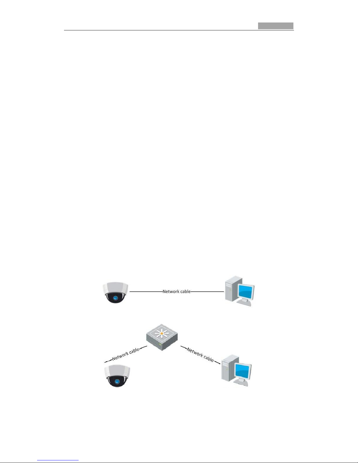
The following diagrams show the two ways of connecting an IP network camera to
computer:
To test the IP network camera, you can directly connect the IP network camera
to the computer with a network cable as shown in Figure 2-1.
Refer to the Figure 2-2 to set the IP network camera up over LAN via a
switch/router.
Figure 2-1 Connecting Directly
Figure 2-2 Connecting via a Switch or a Router
Page 9
SmartWatch® IP Network Camera User Manual
9 9
2.1.2 Detecting and Changing the IP Address
You need the IP address to connect to the IP network camera.
Steps:
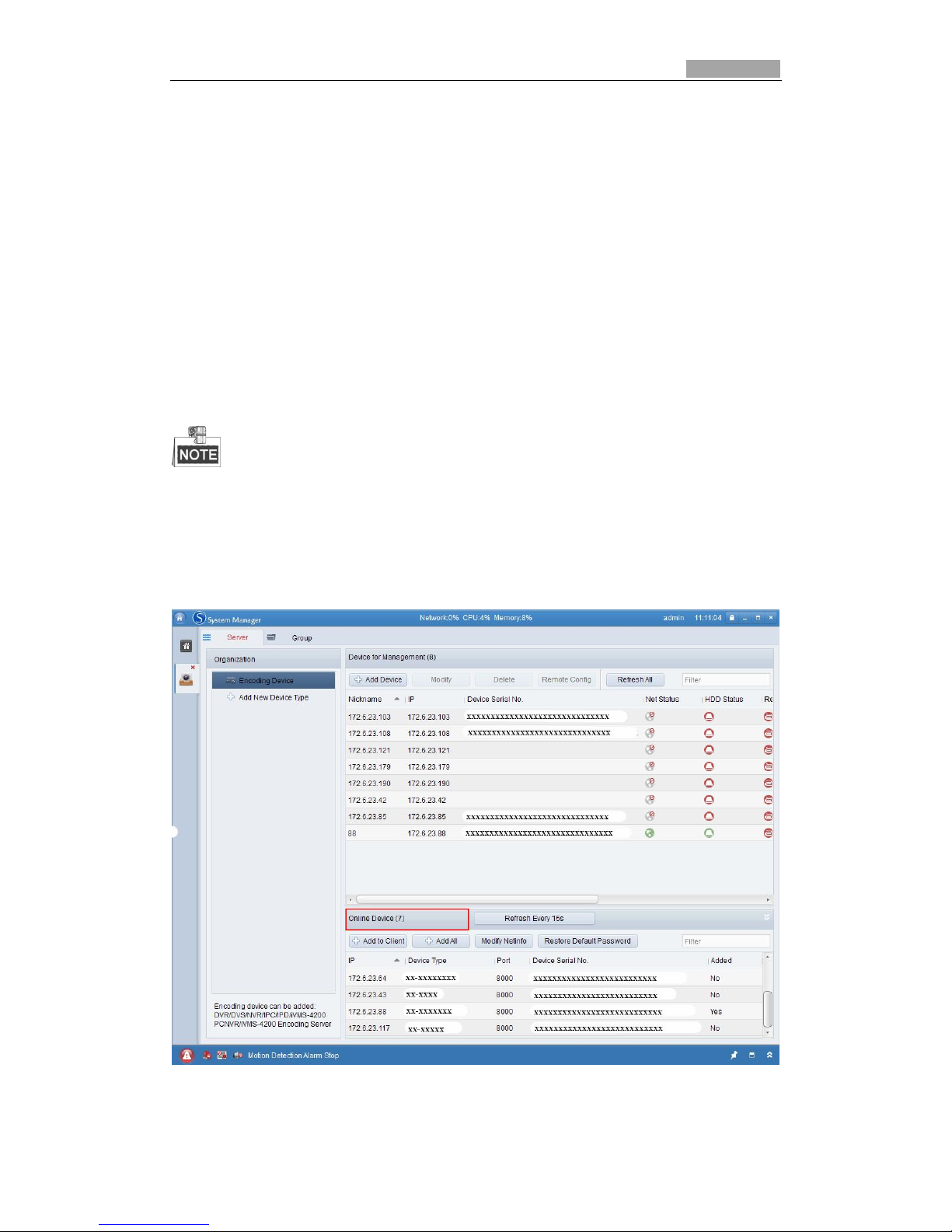
1. To get the IP address, install the System Manager client software. This will
display a list of online devices. Please refer to the user manual of System
Manager client software for more detailed information.
2. Change the IP address and subnet mask to the same range as that of your
computer.
3. Enter the IP address of the IP network camera in the address field of the web
browser to view the live video.
The default IP address is 192.0.0.64 and the port number is 8000. The default user name
is admin, and password is 12345.
For accessing the IP network camera from different subnets, please set the gateway for
the IP network camera after logging in. For more detailed information, please refer to
Section 5.3.1 Configuring TCP/IP Settings.
Figure 2-3 System Manager Interface
Page 10
SmartWatch® IP Network Camera User Manual
10 10
2.2 Setting the IP network camera over WAN
This section explains how to connect to the IP network camera via WAN with a static
IP or a dynamic IP.
2.2.1 Static IP Connection
Before you start:
Please apply for a static IP from an ISP (Internet Service Provider). With the static IP
address, you can connect the IP network camera via a router.
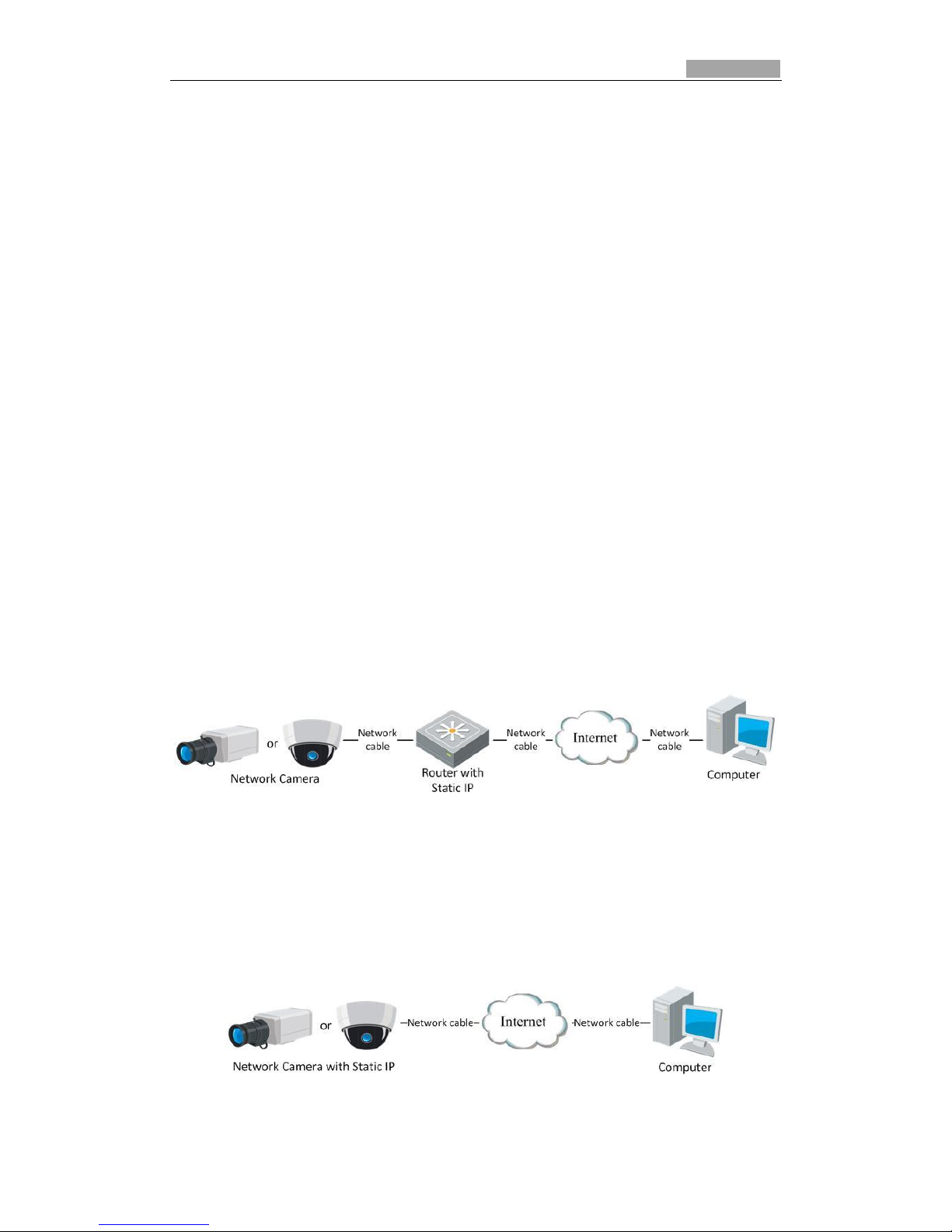
Connecting the IP network camera via a router
Steps:
1. Connect the IP network camera to the router.
2. Assign a LAN IP address, the subnet mask and the gateway. Refer to Section 2.1.2
Detecting and Changing the IP Address for detailed IP address configuration of
the camera.
3. Save the static IP address in the router.
4. Set port mapping, e.g., 80, 8000, 8200 and 554 ports. Port mapping will vary
depending on what router you have. Please refer to the router manufacturer.
5. Connect to the IP network camera through a web browser or the client software
over the internet.
Figure 2-4 Accessing the Camera through Router with Static IP
Connecting the IP network camera with static IP directly
You can also save the static IP address in the camera and directly connect it to the
internet without using a router. Refer to Section 2.1.2 Detecting and Changing the IP
Address for detailed IP address configuration of the camera.
Figure 2-5 Accessing the Camera with Static IP Directly
Page 11
SmartWatch® IP Network Camera User Manual
11 11
2.2.2 Dynamic IP Connection
Before you start:
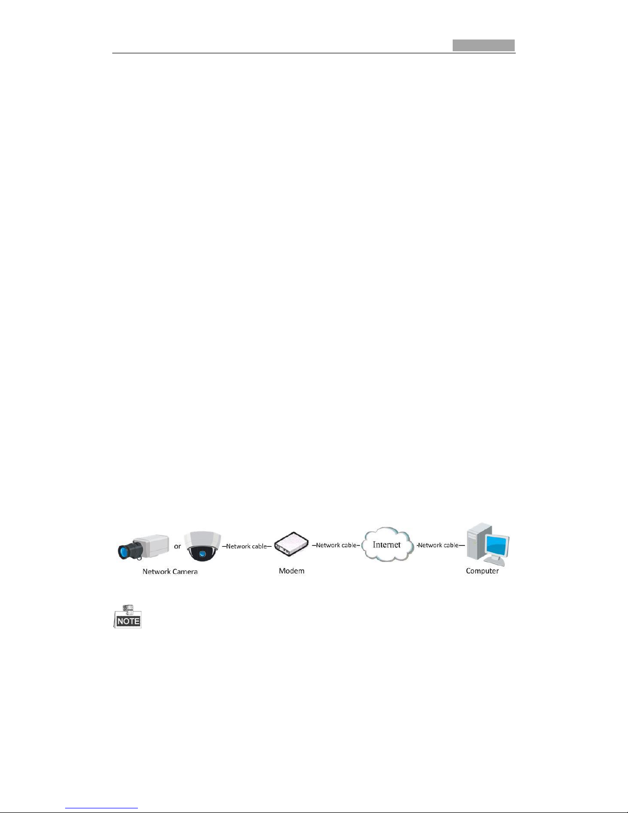
If you have a dynamic IP from an ISP, you can connect the IP network camera to a
modem or a router.
Connecting the IP network camera via a router
Steps:
1. Connect the IP network camera to the router.
2. In the camera, assign a LAN IP address, the subnet mask and the gateway. Refer
to Section 2.1.2 Detecting and Changing the IP Address for detailed LAN
configuration.
3. In the router, set the PPPoE user name, password and confirm the password.
4. Set port mapping. E.g. 80, 8000, 8200 and 554 ports. The steps for port mapping
may vary depending on the router.
5. Apply a domain name from a domain name provider.
6. Configure the DDNS settings in the router.
7. Connect to the camera via the applied domain name.
Connecting the IP network camera via a modem
This camera supports the PPPoE auto dial-up function. The camera automatically gets
a public IP address by ADSL dial-up after the camera is connected to a modem. You
need to configure the PPPoE parameters of the IP network camera. Refer to Section
5.3.3 Configuring PPPoE Settings for detailed configuration.
Figure 2-6 Accessing the Camera with Dynamic IP
The obtained IP address is dynamically assigned via PPPoE, so the IP address always changes
after rebooting the camera. To solve the inconvenience of the dynamic IP, you need to get a
domain name from the DDNS provider (E.g. DynDns.com). Please follow below steps for
normal domain name resolution and private domain name resolution to solve the problem.
Normal Domain Name Resolution
Page 12
SmartWatch® IP Network Camera User Manual
12 12
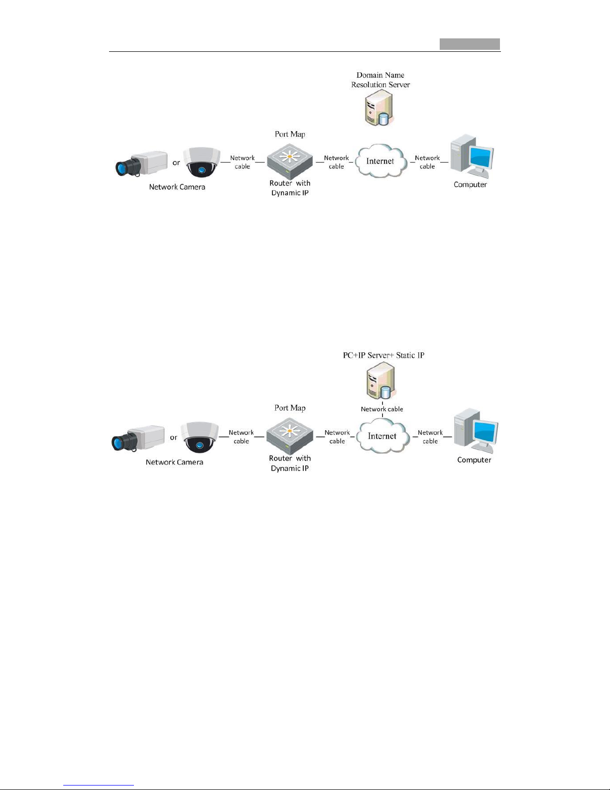
Figure 2-7 Normal Domain Name Resolution
Steps:
1. Apply a domain name from a domain name provider.
2. Configure the DDNS settings in the DDNS Settings interface of the IP network
camera. Refer to Section 5.3.4 Configuring DDNS Settings for detailed
configuration.
3. Connect to the camera via the applied domain name.
Private Domain Name Resolution
Figure 2-8 Private Domain Name Resolution
Steps:
1. Install and run the IP Server software in a computer with a static IP.
2. Access the IP network camera through the LAN with a web browser or the client
software.
3. Enable DDNS and select IP Server as the protocol type. Refer to Section 5.3.4
Configuring DDNS Settings for more detailed configuration.
Page 13
SmartWatch® IP Network Camera User Manual
13
Chapter 3 Access to the IP network
camera
3.1 Accessing by Web Browsers
Steps:
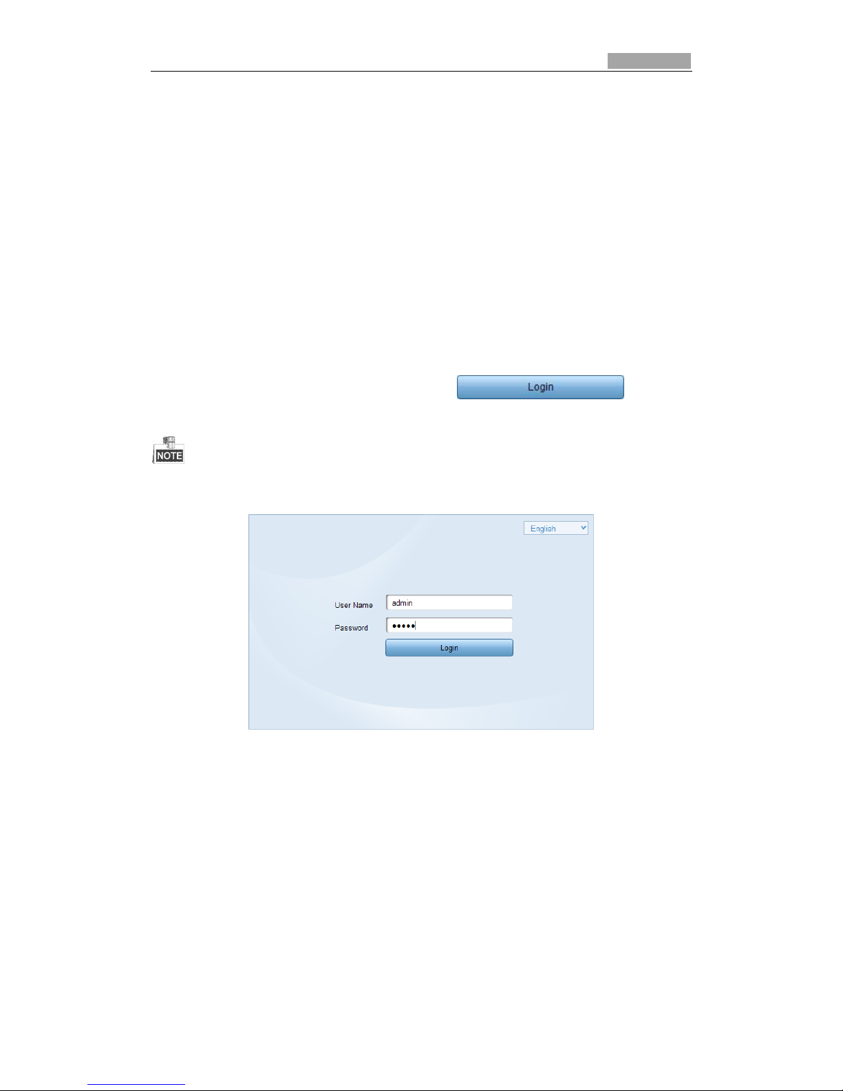
1. Open the web browser.
2. In the address bar, input the IP address of the IP network camera, e.g.,
192.0.0.64 and hit the enter key to enter the login interface.
3. Input the user name and password and click .
The default user name is admin, password is 12345.
Figure 3-1 Login Interface
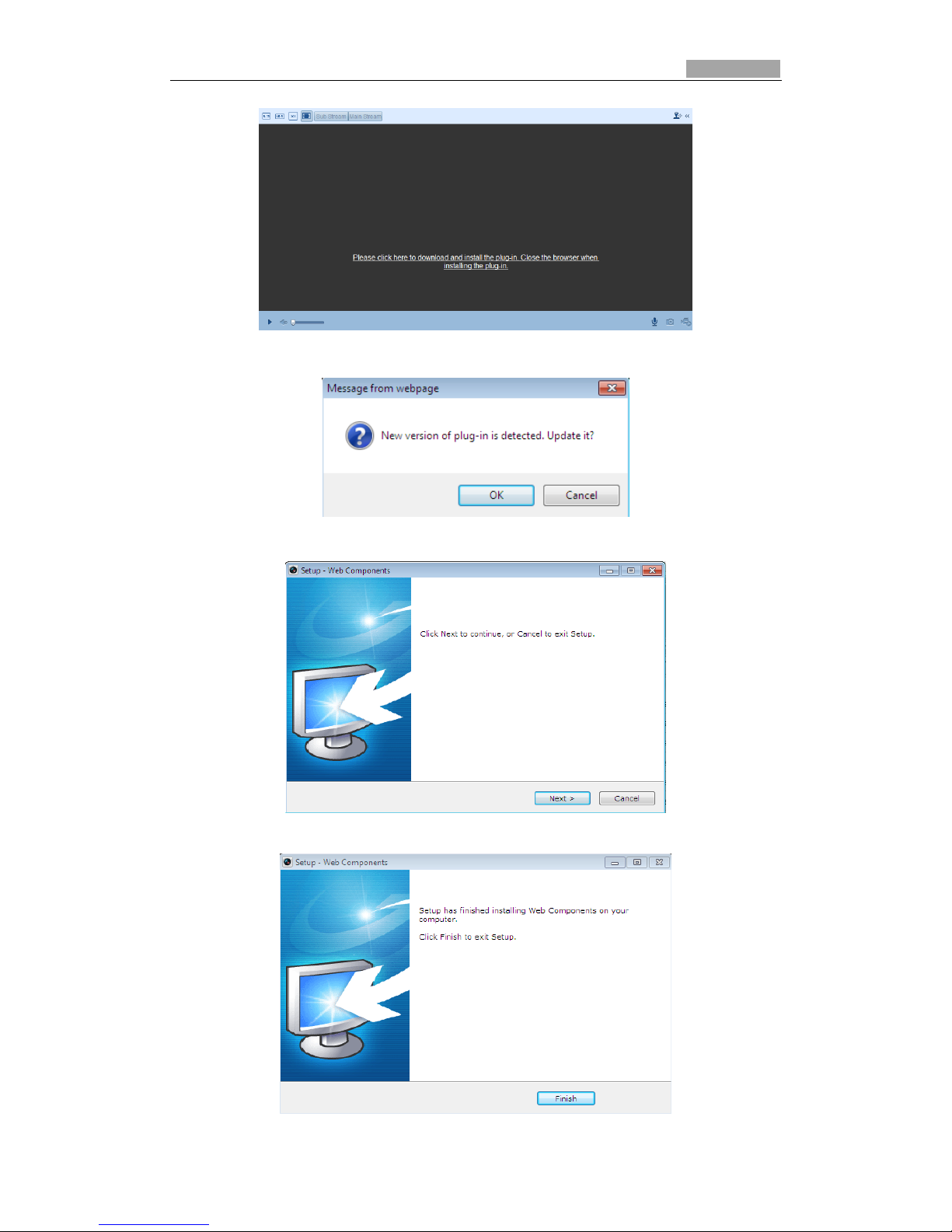
4. Install the plug-in before viewing the live video and operating the camera.
Please follow the installation prompts to install the plug-in.
Page 14
SmartWatch® IP Network Camera User Manual
14 14
Figure 3-2 Download and Install Plug-in
Figure 3-3 Install Plug-in (1)
Figure 3-4 Install Plug-in (2)
Page 15
SmartWatch® IP Network Camera User Manual
15 15
Figure 3-5 Install Plug-in (3)
Figure 3-6
You may have to close the web browser to install the plug-in. Please reopen the web
browser and log back in again after installing the plug-in.
3.2 Accessing by Client Software
3.2.1 Accessing by System Manager Software
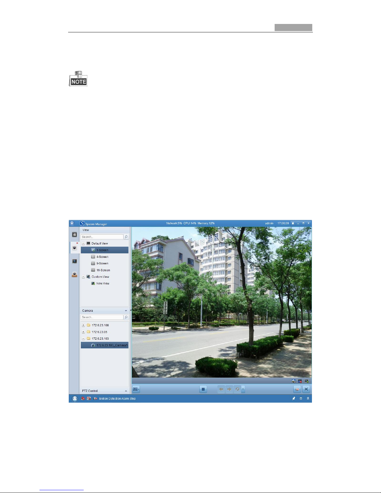
The product CD contains the System Manager client software (Client or PCNVR). You
can view the live video and manage the camera with the client software.
Follow the installation prompts to install the software. The control panel and live
view interface of System Manager are displayed below.
Figure 3-7 System Manager Live View
Page 16
SmartWatch® IP Network Camera User Manual
16 16
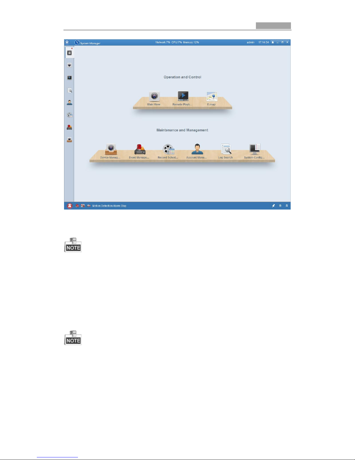
Figure 3-8 System Manager Configuration Panel
For detailed information about System Manager client software, please refer to the user
manual of the System Manager software.
3.2.2 Accessing by SmartWatch® Viewer Software
To view the camera with a mobile phone, install the SmartWatch® Viewer software
on your mobile phone.
For detailed information about SmartWatch® Viewer software, please refer to the user
manual of the SmartWatch® Viewer software.
Page 17
SmartWatch® IP Network Camera User Manual
17
Chapter 4 Live View
4.1 Live View Screen
The live video page allows you to view live video, capture images, PTZ control,
set/call presets and configure video parameters.
Log in to the IP network camera to enter the live view page.
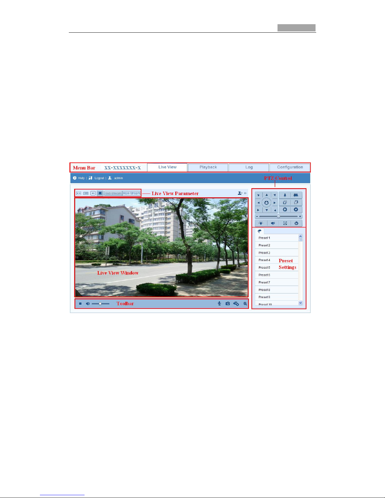
Descriptions of the live view page:
Figure 4-1 Live View Page
Menu Bar:
Click each tab to enter Live View, Playback, Log and Configuration page respectively.
Live View Window:
Display the live video.
Toolbar:
Operations on the live view page, e.g., live view, capture, record, audio on/off,
two-way audio, etc.
PTZ Control:
Panning, tilting and zooming actions of the PTZ camera and the lighter and wiper
control (if it supports PTZ function or an external pan/tilt unit has been installed).
Preset Setting/Calling:
Set and call the preset for the camera (if supports PTZ function or an external
pan/tilt unit has been installed).
Page 18
SmartWatch® IP Network Camera User Manual
18 18
Live View Parameters:
Configure the image size and stream type of the live video.
4.2 Starting Live View
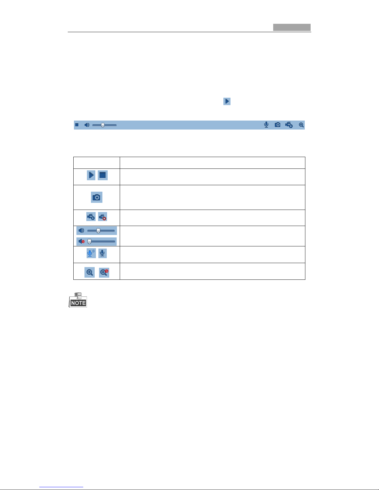
In the live view window as shown in Figure 4-2, click on the toolbar to start the
live view of the camera.
Figure 4-2 Live View Toolbar
Table 4-1 Descriptions of the Toolbar
Icon
Description
/
Start/Stop live view
Manually capture images displayed in live view and save them
as a JPEG file.
/
Manually start/stop recording.
Audio on and adjust volume /Mute.
/
Enable/Disable two-way audio.
/
Enable/Disable PTZ.
Before using the two-way audio function or recording with audio, please set the Stream Type
to Video & Audio (please refer to Section 5.4).
Full-screen Mode
You can double-click on the live video screen to switch the current live view into
full-screen or return back to normal mode from the full-screen.
Please refer to the following sections for more information:
Configuring remote recording in Section 6.2 Configuring Recording Schedule.
Setting the image quality of the live video in Section 5.1 Configuring Local
Parameters and Section 5.4.1 Configuring Video Settings.
Setting the OSD text on live video in Section 5.5.2 Configuring OSD Settings.
Page 19
SmartWatch® IP Network Camera User Manual
19 19
4.3 Recording and Capturing Images Manually
In the live view screen, click on the toolbar to capture the live images or click
to record the live video. The location that the images and video recordings can
can be set in the Configuration > Local Configuration page.
Please note that the captured image will be saved as a JPEG file in your computer.
4.4 Operating PTZ Control
In the live view screen, you can use the PTZ control buttons to control the camera (if
PTZ camera connected).
Before you start:
Please configure the PTZ parameters on RS-485 Settings page referring to Section
10.6 RS-485 Settings.
4.4.1 PTZ Control Panel
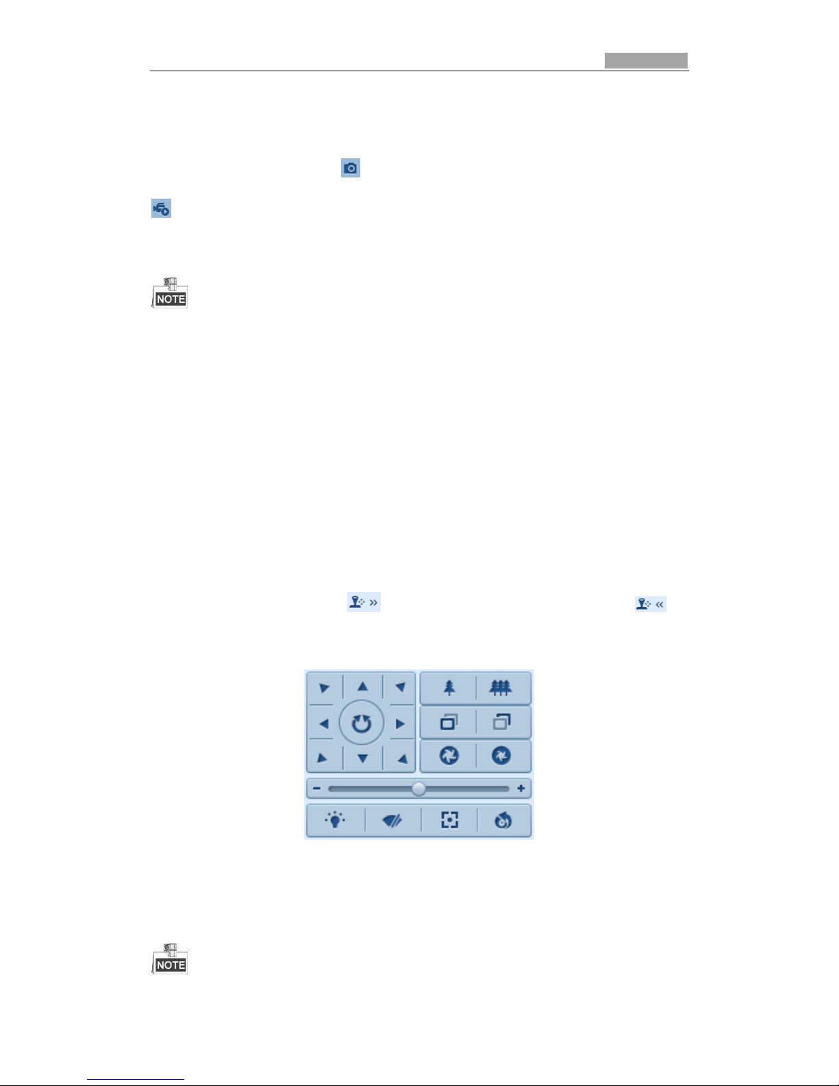
On the live view screen, click to show the PTZ control panel / click to
hide it.
Click the direction buttons to control the pan/tilt direction.
Figure 4-3 PTZ Control Panel
Click the zoom/iris/focus buttons for lens control.
Page 20
SmartWatch® IP Network Camera User Manual
20 20
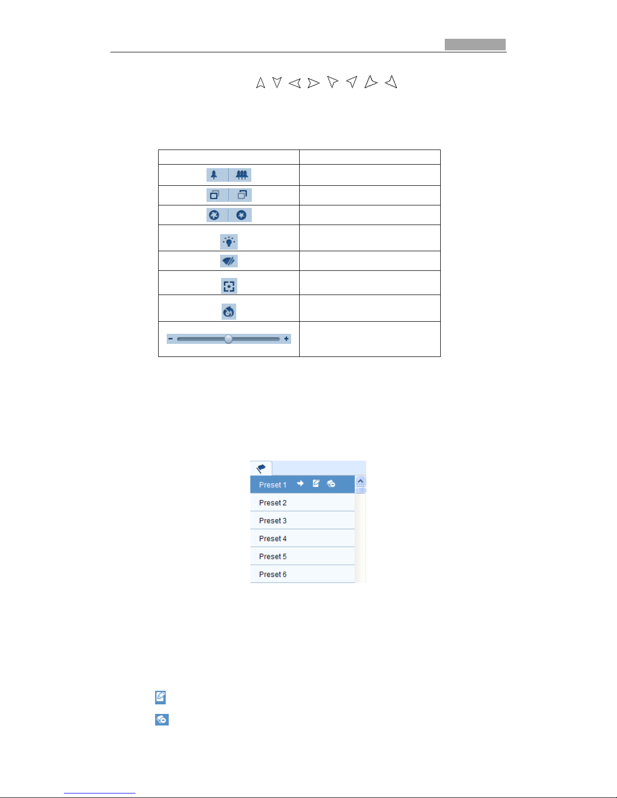
There are 8 direction arrows ( , , , , , , , ) in the live view window.
For the cameras that support lens control only, the direction buttons will be invalid.
Table 4-2 Descriptions of PTZ Control Panel
Button
Description
Zoom in/out
Focus near/far
Iris open/close
Light on/off
Wiper on/off
One-touch focus
Initialize lens
Adjust speed of pan/tilt
movements
4.4.2 Setting / Calling a Preset
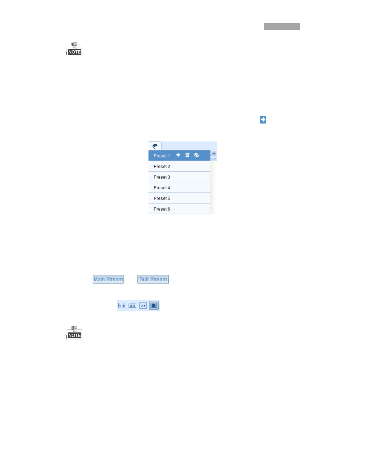
Setting a Preset:
1. In the PTZ control panel, select a preset number from the preset list.
Figure 4-4 Setting a Preset
2. Use the PTZ control buttons to move the lens to the desired position.
• Pan the camera to the right or left.
• Tilt the camera up or down.
• Zoom in or out.
• Refocus the lens.
3. Click to save the setting of the current preset.
4. Click to delete the preset.
Page 21
SmartWatch® IP Network Camera User Manual
21 21
You can configure up to 128 presets.
Calling a Preset:
This feature enables the camera to call a specified preset position manually or when
an event takes place.
In the PTZ control panel, select a defined preset from the list and click to call the
preset.
Figure 4-5 Calling a Preset
4.5 Configuring Live View Parameters
You can select the stream type and adjust the image size on the live view page.
Click or tab under the menu bar of the live view
interface to select the stream type as main stream or sub-stream for live viewing.
Click each tab to set the image size to 4:3, 16:9, and original.
Please refer to Section 5.4.1 Configuring Video Settings for more detailed settings about
video parameters.
Page 22
SmartWatch® IP Network Camera User Manual
22
Chapter 5 IP network camera
Configuration
5.1 Configuring Local Parameters
The local configuration refers to the parameters of live view, record files and captured images.
The record files and captured images are the files saved using the web browser. The saving
paths are on the PC running the browser.
Steps:
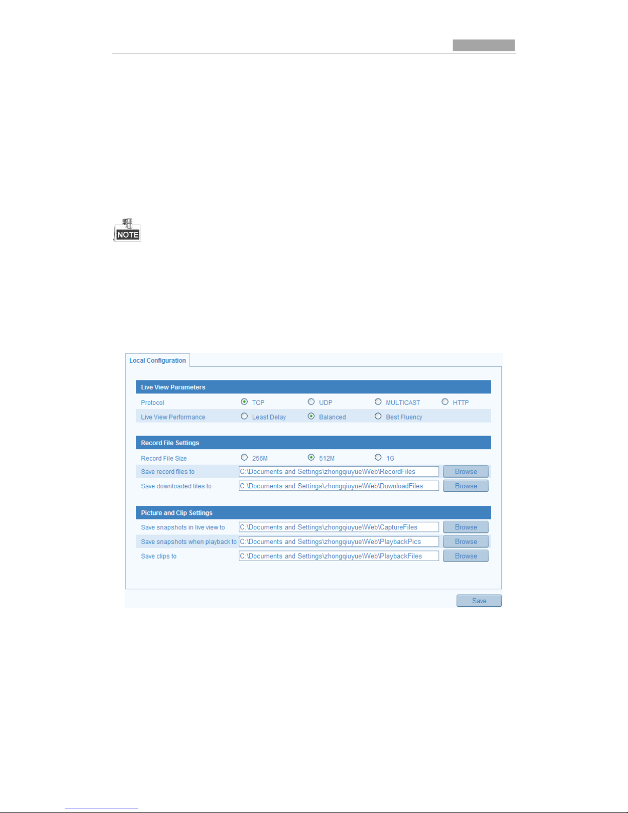
1. Enter the Local Configuration interface:
Configuration > Local Configuration
Figure 5-1 Local Configuration Interface
2. Configure the following settings:
Live View Parameters: Set the protocol type and live view performance.
Protocol Type: TCP, UDP, MULTICAST and HTTP are selectable.
TCP: Ensures complete delivery of streaming data and better video quality,
yet the real-time transmission may be affected.
UDP: Provides real-time audio and video streams.
HTTP: Allows the same quality as of TCP without setting specific ports for
Page 23
SmartWatch® IP Network Camera User Manual
23 23
streaming under some network environments.
MULTICAST: It’s recommended to select MCAST type when using the
Multicast function. For detailed information about Multicast, refer to Section
5.3.1 TCP/IP Settings.
Live View Performance: Set the live view performance to Least Delay,
Balanced or Best Fluency.
Record File Settings: Set the desired location for the recorded video files
recorded with the web browser.
Record File Size: Select the maximum size of the manually recorded and
downloaded video files to 256M, 512M or 1G.
Save record files to: Set the saving path for the manually recorded video files.
Save downloaded files to: Set the saving path for the downloaded video files
in playback mode.
Picture and Clip Settings: Set the desired location the captured images and video
files.
Save snapshots in live view to: Set the desired location for the manually
captured images in live view mode.
Save snapshots when playback to: Set the desired location for the captured
images in playback mode.
Save clips to: Set the desired location for the clipped video files in playback
mode.
You can click to change the directory for saving the clips and images.
3. Click to save the settings.
5.2 Configuring Time Settings
Please follow the instructions in this section to configure the time synchronization
and DST settings.
Steps:
1. Enter the Time Settings interface:
Configuration > Basic Configuration > System > Time Settings
Or Configuration > Advanced Configuration > System > Time Settings
Page 24
SmartWatch® IP Network Camera User Manual
24 24
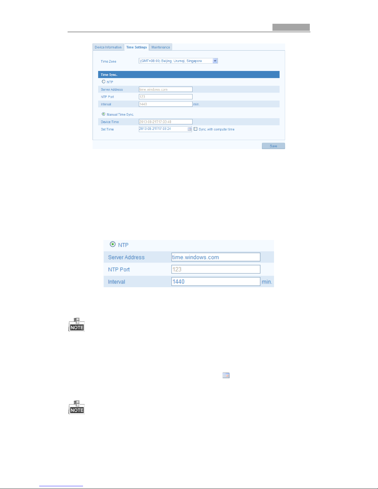
Figure 5-2 Time Settings
Select the Time Zone.
Select the Time Zone you are in from the drop-down menu.
Synchronizing Time using a NTP Server.
(1) Check to enable the NTP function.
(2) Configure the following settings:
Server Address: IP address of NTP server.
NTP Port: Port of NTP server.
Interval: The time interval between synchronizing.
Figure 5-3 Time Sync by NTP Server
If the camera is connected to a public network, you should use a NTP server that has a time
synchronization function.
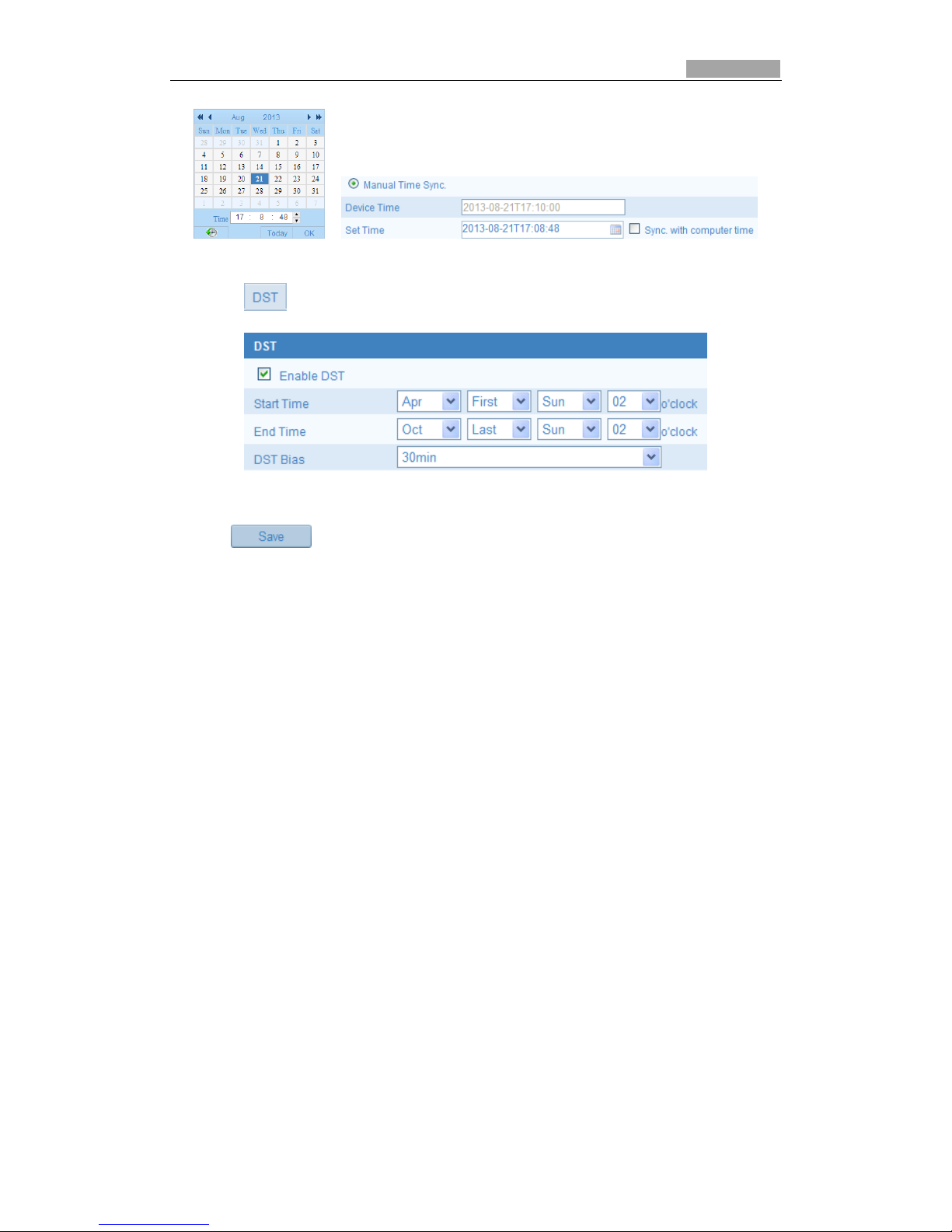
Synchronizing Time Synchronization Manually
Enable the Manual Time Sync function and then click to set the system time
from the pop-up calendar.
You can also select Sync with computer time to synchronize the camera time with your
computer.
Page 25
SmartWatch® IP Network Camera User Manual
25 25
Figure 5-4 Time Sync Manually
Click tab to enable the DST function and Set the date of the DST period.
Figure 5-5 DST Settings
2. Click to save the settings.
5.3 Configuring Network Settings
5.3.1 Configuring TCP/IP Settings
TCP/IP settings must be properly configured before you operate the camera over
network. The camera supports both the IPv4 and IPv6. Both versions may be
configured simultaneously without conflict at least one IP version should be
configured.
Steps:
1. Enter TCP/IP Settings interface:
Configuration > Basic Configuration > Network > TCP/IP
Or Configuration > Advanced Configuration > Network > TCP/IP
Page 26
SmartWatch® IP Network Camera User Manual
26 26
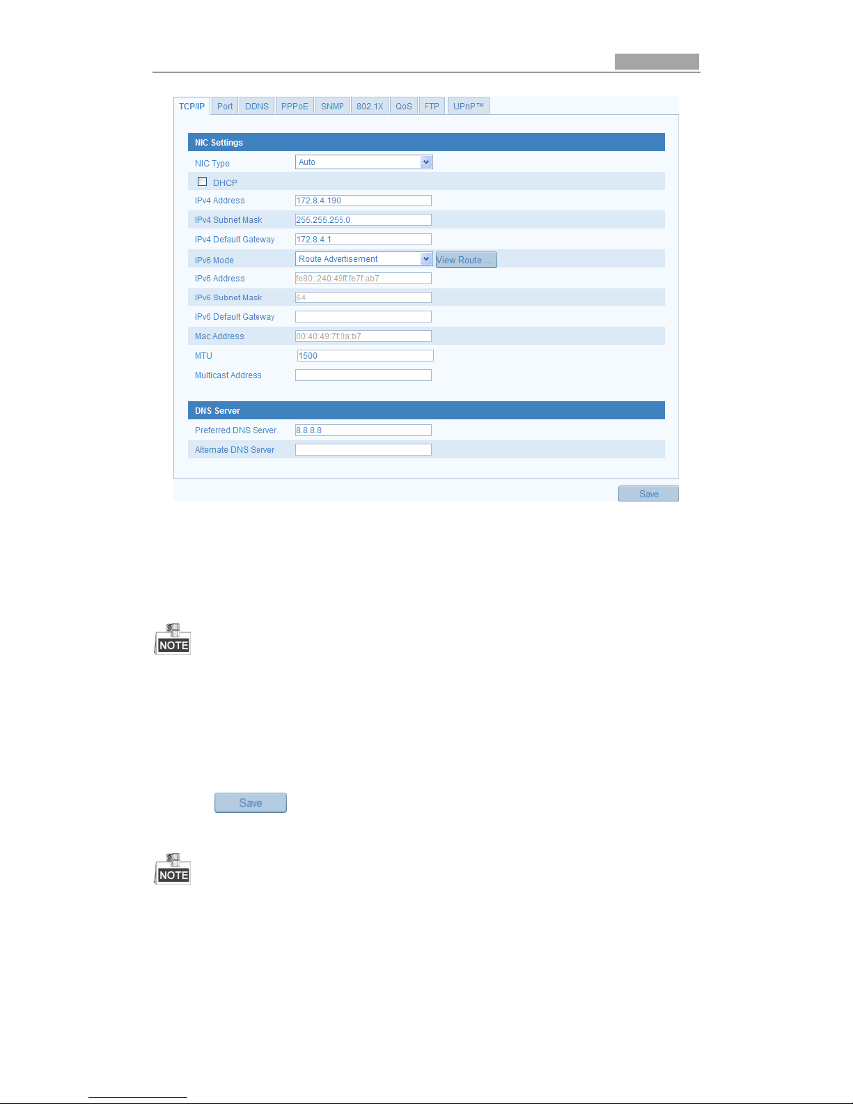
Figure 5-6 TCP/IP Settings
2. Configure the basic network settings, including the NIC Type, IPv4 or IPv6 Address,
IPv4 or IPv6 Subnet Mask, IPv4 or IPv6 Default Gateway, MTU settings and
Multicast Address.
The valid value range of MTU is 500 ~ 1500.
The Multicast sends a stream to the multicast group address and allows multiple clients
to acquire the stream at the same time by requesting a copy from the multicast group
address. Before utilizing this function, you have to enable the Multicast function of your
router.
3. Click to save the above settings.
A reboot is required for the settings to take effect.
5.3.2 Configuring Port Settings
You can set the port No. of the camera, e.g. HTTP port, RTSP port and HTTPS port.
Page 27
SmartWatch® IP Network Camera User Manual
27 27
Steps:
1. Enter the Port Settings:
Configuration > Basic Configuration > Network > Port
Or Configuration > Advanced Configuration > Network > Port
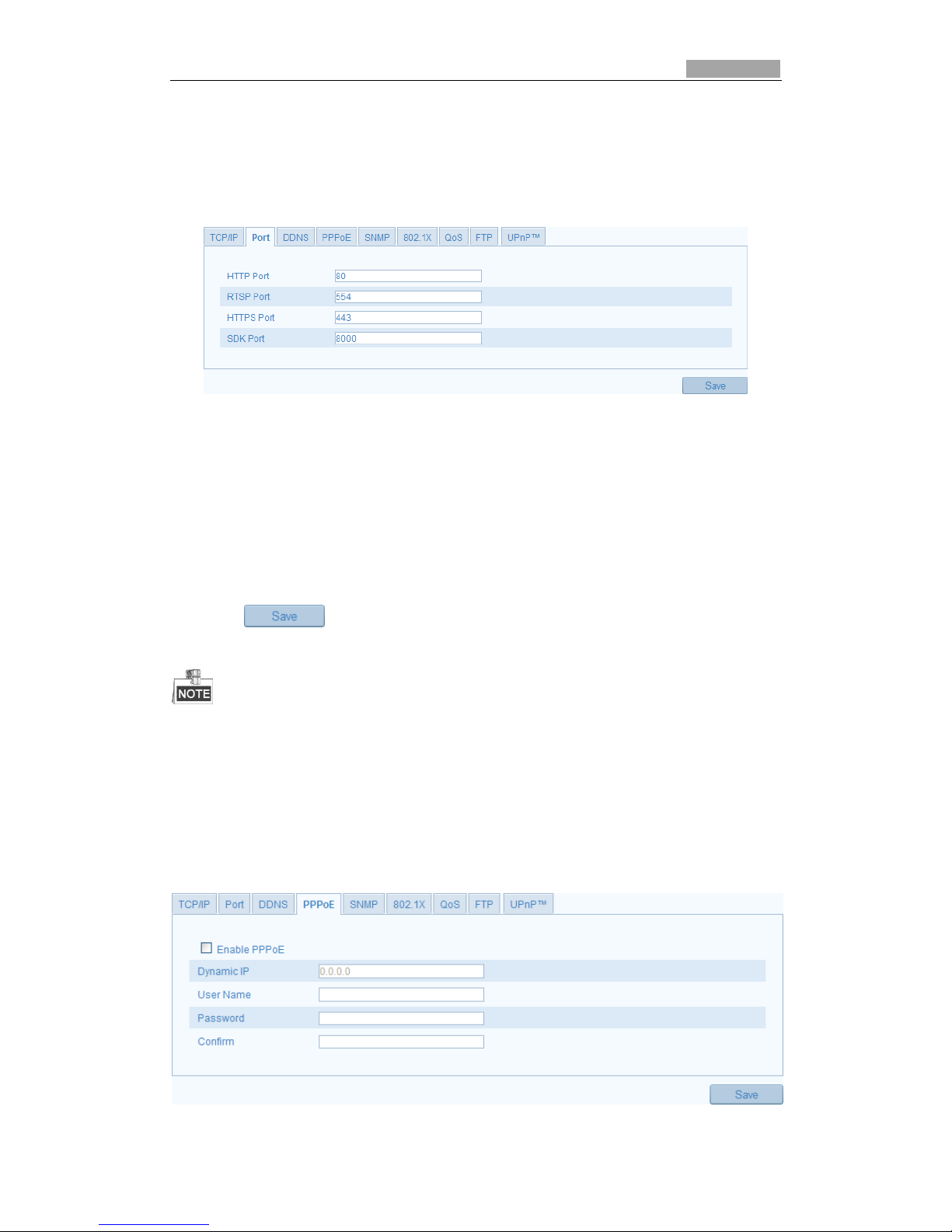
Figure 5-7 Port Settings
2. Set the HTTP port, RTSP port and HTTPS port of the camera.
HTTP Port: The default port number is 80, and can be changed to any port range
1024 to 65535.
RTSP Port: The default port number is 554.
HTTPS Port: The default port number is 443, and can be changed to any port
range 1024 to 65535.
SDK Port: The default SDK port number is 8000.
3. Click to save the settings.
A reboot is required for the settings to take effect.
5.3.3 Configuring PPPoE Settings
Steps:
1. Enter the PPPoE Settings interface:
Configuration >Advanced Configuration > Network > PPPoE
Page 28
SmartWatch® IP Network Camera User Manual
28 28
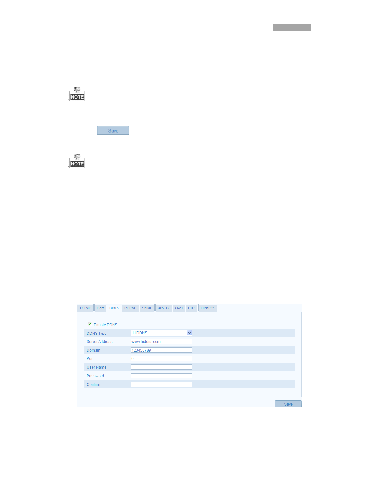
Figure 5-8 PPPoE Settings
2. Check the Enable PPPoE checkbox to enable this feature.
3. Enter User Name, Password, and Confirm password for PPPoE access.
The User Name and Password should be assigned by your ISP.
4. Click to save and exit the interface.
A reboot is required for the settings to take effect.
5.3.4 Configuring DDNS Settings
If your camera is set to use PPPoE as its default network connection, you can use the
Dynamic DNS (DDNS) for network access.
Before you start:
Registration on the DDNS server is required before configuring the DDNS settings of
the camera.
Steps:
1. Enter the DDNS Settings interface:
Configuration > Advanced Configuration > Network > DDNS
Figure 5-9 DDNS Settings
2. Check the Enable DDNS checkbox to enable this feature.
3. Select DDNS Type. Three DDNS types are selectable: HiDDNS, IPServer and
DynDNS.
Page 29
SmartWatch® IP Network Camera User Manual
29 29
DynDNS:
Steps:
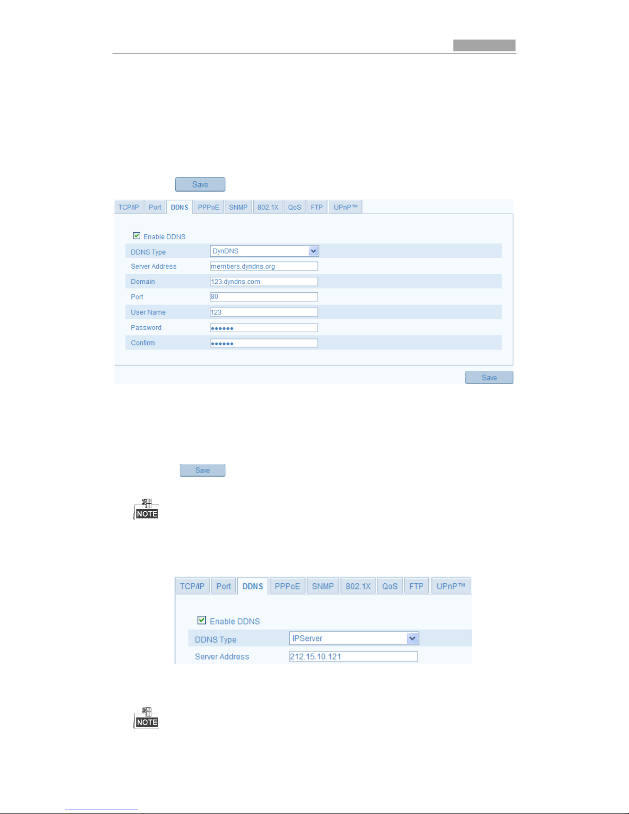
(1) Enter Server Address of DynDNS (e.g. members.dyndns.org).
(2) In the Domain text field, enter the domain name obtained from the DynDNS
website.
(3) Enter the Port of DynDNS server.
(4) Enter the User Name and Password registered on the DynDNS website.
(5) Click to save the settings.
Figure 5-10 DynDNS Settings
IP Server:
Steps:
(1) Enter the Server Address of the IP Server.
(2) Click to save the settings.
For the IP Server, you have to apply a static IP, subnet mask, gateway and preferred
DNS from the ISP. The Server Address should be entered with the static IP address of
the computer that runs the IP Server software.
Figure 5-11 IPServer Settings
Page 30
SmartWatch® IP Network Camera User Manual
30 30
For the US and Canada area, you can enter 173.200.91.74 as the server address.
HiDDNS
Steps:
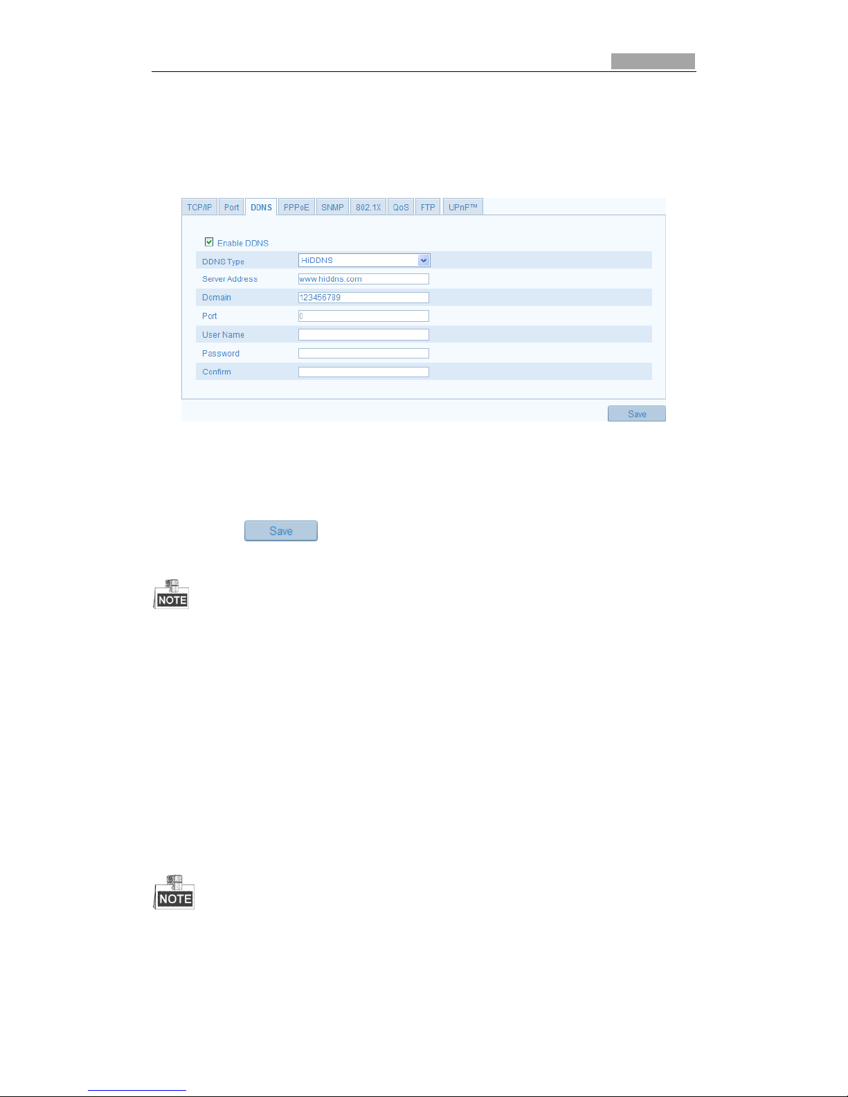
(1) Choose the DDNS Type as HiDDNS.
Figure 5-12 HiDDNS Settings
(2) Enter the Server Address www.hiddns.com.
(3) Enter the Domain name of the camera. The domain is the same with the
device alias in the HiDDNS server.
(4) Click to save the new settings.
A reboot is required for the settings to take effect.
5.3.5 Configuring SNMP Settings
You can set the SNMP function to get camera status, parameters and alarm related
information and manage the camera remotely when it is connected to the network.
Before you start:
Before setting the SNMP, please download the SNMP software and manage to
receive the camera information via SNMP port. By setting the Trap Address, the
camera can send the alarm event and exception messages to the surveillance center.
The SNMP version you select should be the same as that of the SNMP software. And you
also need to use the different version according to the security level you required. SNMP v1
provides no security and SNMP v2 requires password for access. And SNMP v3 provides
encryption and if you use the third version, HTTPS protocol must be enabled.
Page 31
SmartWatch® IP Network Camera User Manual
31 31
Steps:
1. Enter the SNMP Settings interface:
Configuration > Advanced Configuration > Network > SNMP
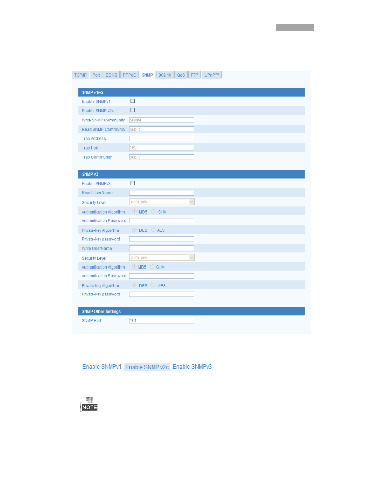
Figure 5-13 SNMP Settings
2. Check the corresponding version checkbox
( , , ) to enable the feature.
3. Configure the SNMP settings.
The settings of the SNMP software should be the same as the settings you configure
here.
Page 32
SmartWatch® IP Network Camera User Manual
32 32
4. Click to save and finish the settings.
A reboot is required for the settings to take effect.
5.3.6 Configuring 802.1X Settings
The IEEE 802.1X standard is supported by the IP network cameras, and when the
feature is enabled, the camera data is secured and user authentication is needed
when connecting the camera to the network protected by the IEEE 802.1X.
Before you start:
The authentication server must be configured. Please apply and register a user name
and password for 802.1X in the server.
Steps:
1. Enter the 802.1X Settings interface:
Configuration > Advanced Configuration > Network > 802.1X
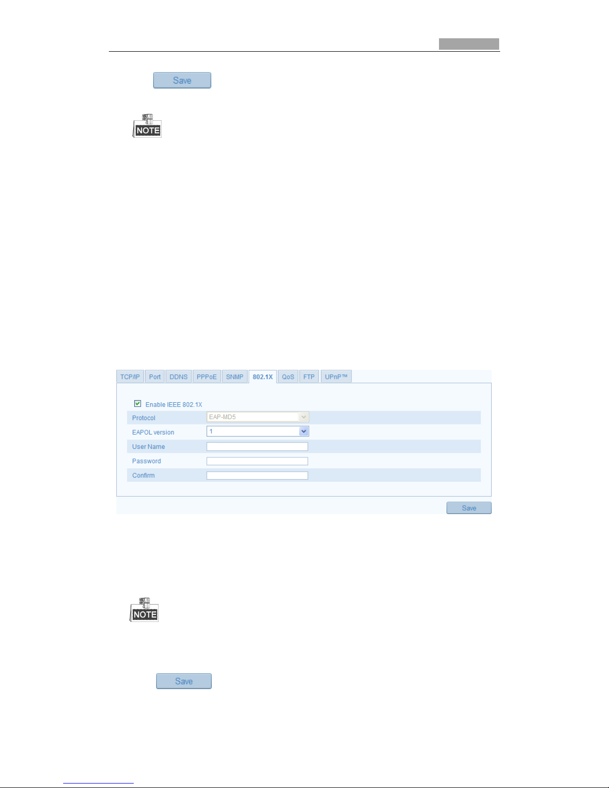
Figure 5-14 802.1X Settings
2. Check the Enable IEEE 802.1X checkbox to enable the feature.
3. Configure the 802.1X settings, including EAPOL version, user name and
password.
The EAPOL version must be identical with that of the router or the switch.
4. Enter the user name and password to access the server.
5. Click to finish the settings.
Page 33
SmartWatch® IP Network Camera User Manual
33 33
A reboot is required for the settings to take effect.
5.3.7 Configuring QoS Settings
QoS (Quality of Service) can help solve the network delay and network congestion by
configuring the priority of data sending.
Steps:
1. Enter the QoS Settings interface:
Configuration >Advanced Configuration > Network > QoS
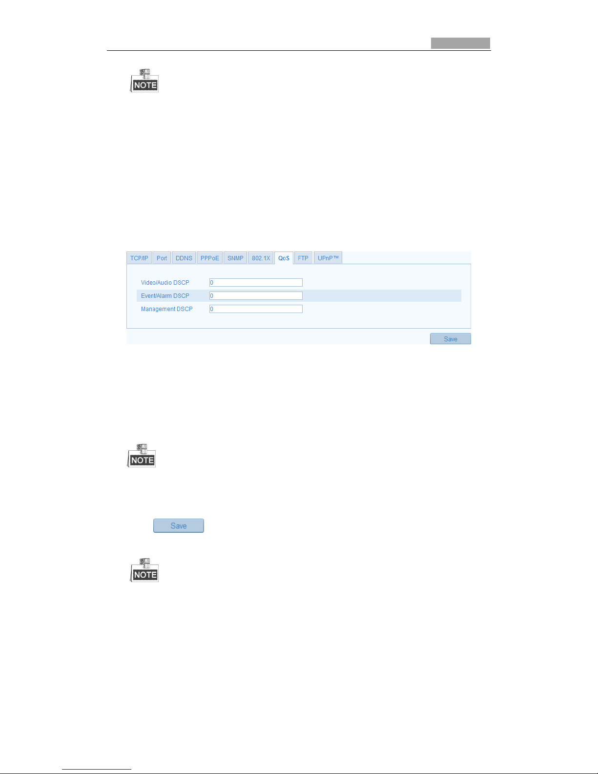
Figure 5-15 QoS Settings
2. Configure the QoS settings, including video / audio DSCP, event / alarm DSCP and
Management DSCP.
The valid value range of the DSCP is 0-63. The bigger the DSCP value is the higher
the priority is.
SCP refers to the Differentiated Service Code Point; and the DSCP value is used in the IP
header to indicate the priority of the data.
3. Click to save the settings.
A reboot is required for the settings to take effect.
5.3.8 Configuring FTP Settings
You can configure the FTP server related information to enable the uploading of the
captured images to the FTP server. The captured images can be triggered by events
or a timing snapshot task.
Page 34
SmartWatch® IP Network Camera User Manual
34 34
Steps:
1. Enter the FTP Settings interface:
Configuration >Advanced Configuration > Network > FTP
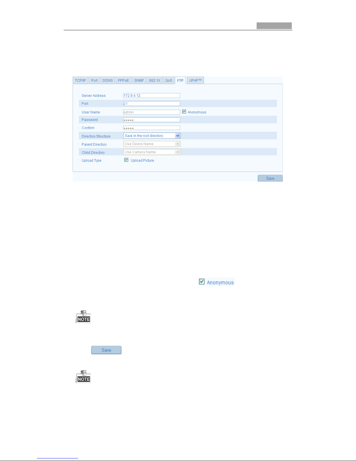
Figure 5-16 FTP Settings
2. Configure the FTP settings; the user name and password are required for login to
the FTP server.
Directory: In the Directory Structure field, you can select the root directory,
parent directory and child directory. When the parent directory is selected, you
have the option to use the Device Name, Device Number or Device IP for the
name of the directory; and when the Child Directory is selected, you can use the
Camera Name or Camera No. as the name of the directory.
Upload type: To enable uploading the captured image to the FTP server.
Anonymous Access to the FTP Server (in which case the user name and
password won’t be requested.): Check the checkbox to enable
the anonymous access to the FTP server.
The anonymous access function must be supported by the FTP server.
3. Click to save the settings.
If you want to upload the captured images to FTP server, you have to enable the
continuous snapshot or event-triggered snapshot on Snapshot page. For detailed
information, please refer to the Section 5.6.7.
Page 35
SmartWatch® IP Network Camera User Manual
35 35
5.3.9 Configuring UPnP™ Settings
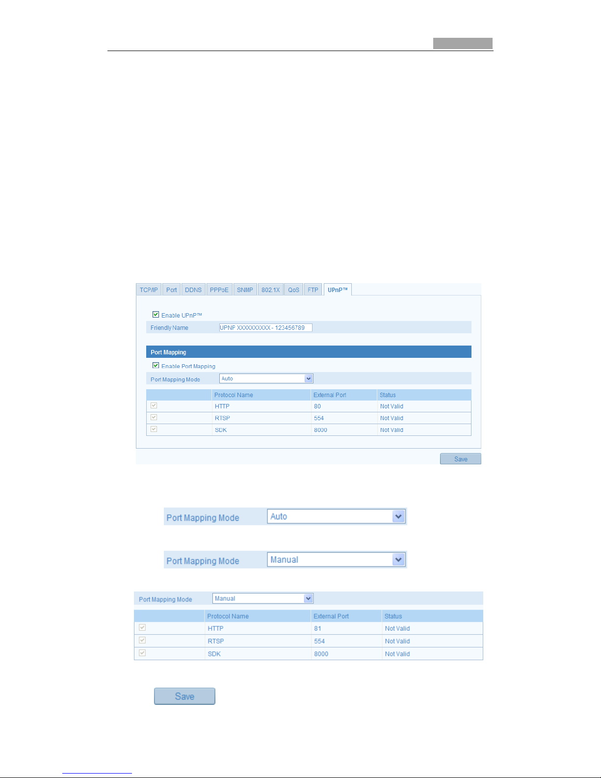
Universal Plug and Play (UPnP™) is a networking architecture that provides
compatibility among networking equipment, software and other hardware devices.
The UPnP protocol allows devices to connect seamlessly and to simplify the
implementation of networks in the home and corporate environments.
With the function enabled, you don’t need to configure the port mapping for each
port, and the camera is connected to the Wide Area Network via the router.
Steps:
1. Enter the UPnP™ settings interface.
Configuration >Advanced Configuration > Network > UPnP
2. Check the checkbox to enable the UPnP™ function.
The name of the device when detected online can be edited.
Figure 5-17 Configure UPnP Settings
To port mapping with the default port numbers:
Choose
To port mapping with the customized port numbers:
Choose
And you can customize the value of the port number by yourself.
Figure 5-18 Modify Port No.
3. Click to save the settings.
Page 36
SmartWatch® IP Network Camera User Manual
36 36
5.4 Configuring Video and Audio Settings
5.4.1 Configuring Video Settings
Steps:
1. Enter the Video Settings interface:
Configuration >Basic Configuration > Video / Audio > Video
Or Configuration > Advanced Configuration > Video / Audio > Video
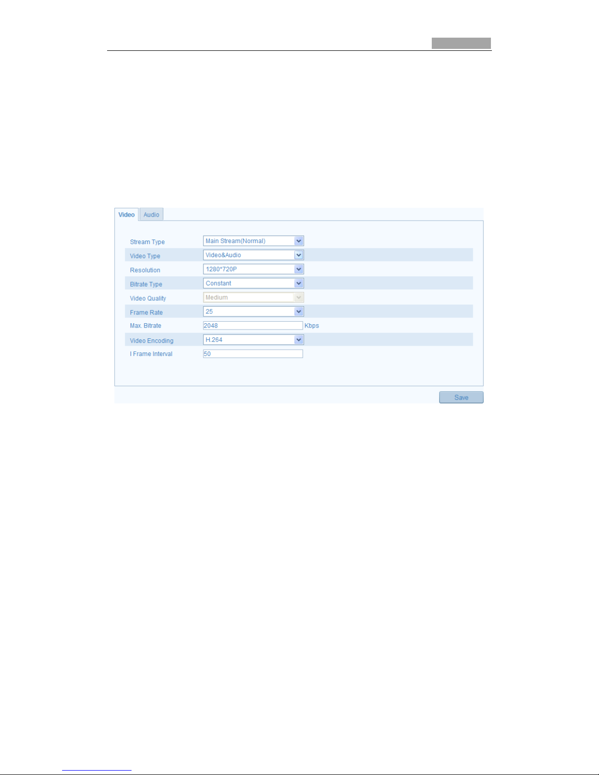
Figure 5-19 Configure Video Settings
2. Select the Stream Type of the camera main stream (normal), or sub-stream.
The main stream is normally used for recording and live viewing with good
bandwidth, and the sub-stream can be used for live viewing when the bandwidth
is limited (mobile device).
3. You can customize the following parameters:
Video Type:
Select the stream type to video stream, or video & audio composite stream. The
audio signal will be recorded only when the Video Type is Video & Audio.
Resolution:
Select the resolution of the video output.
Bitrate Type:
Select the bitrate type to constant or variable.
Video Quality:
When bitrate type is selected as Variable, 6 levels of video quality are selectable.
Frame Rate:
Set the frame rate to 1/16~25 fps. The frame rate is to describe the frequency at
which the video stream is updated and it is measured by frames per second (fps).
A higher frame rate is advantageous when there is movement in the video stream,
as it maintains image quality throughout.
Page 37
SmartWatch® IP Network Camera User Manual
37 37
Max. Bitrate:
Set the max. bitrate to 32~16384 Kbps. The higher value corresponds to the
higher video quality, but the higher bandwidth is required.
Video Encoding:
When the Stream Type of the camera is main stream, the Video Encoding
standard can be set to H.264.
When the Stream Type of the camera is sub-stream, the Video Encoding standard
can be set to H.264, MJPEG.
I Frame Interval:
Set the I-Frame interval to 1~400.
4. Click to save the settings.
5.4.2 Configuring Audio Settings
Steps:
1. Enter the Audio Settings interface
Configuration > Basic Configuration > Video / Audio > Audio
Or Configuration > Advanced Configuration > Video / Audio > Audio
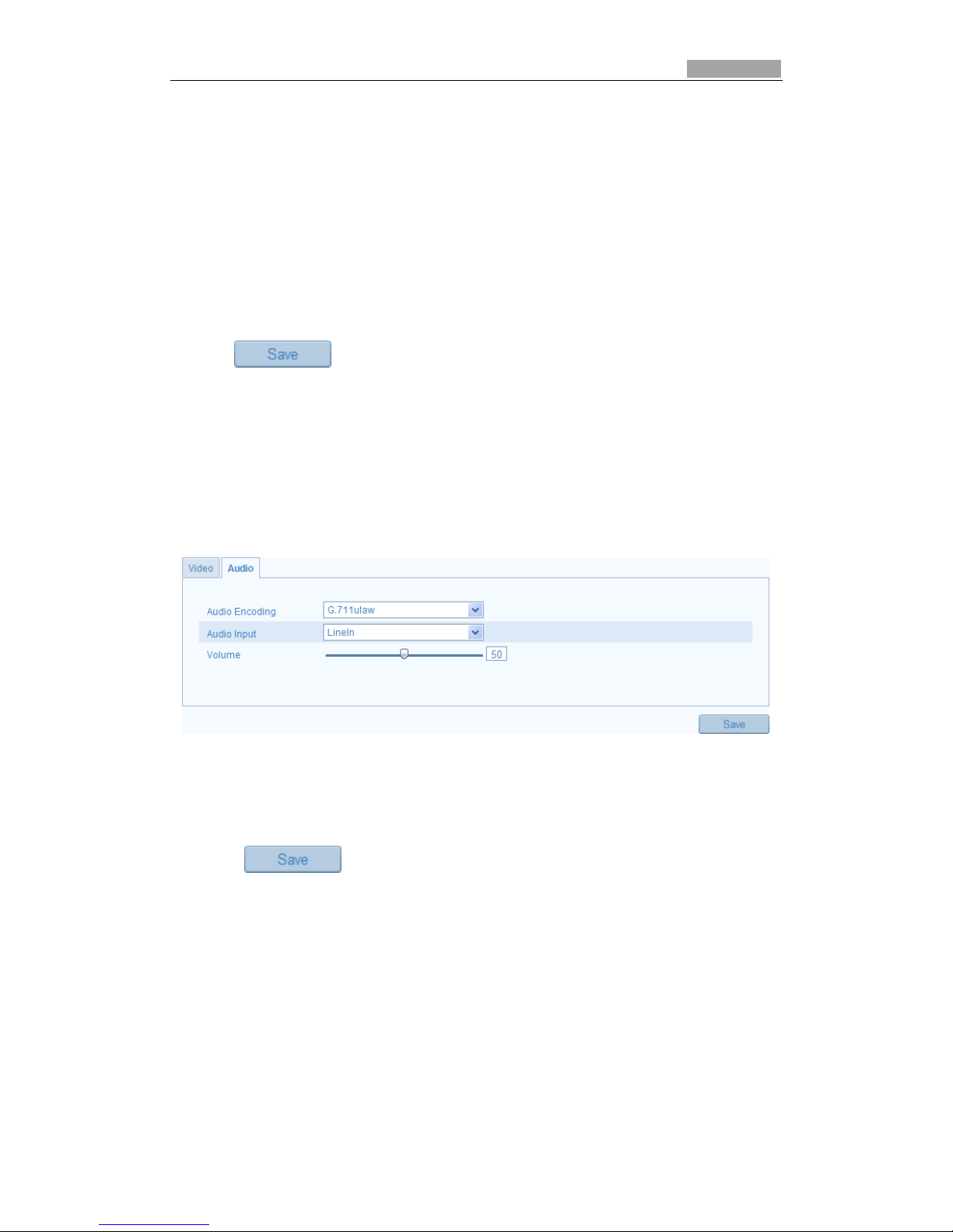
Figure 5-20 Audio Settings
2. Configure the following settings.
Audio Encoding: G.711 ulaw, G.711alaw and G.726 are selectable.
Audio Input: MicIn and Linein are selectable for the connected microphone.
3. Click to save the settings.
5.5 Configuring Image Parameters
5.5.1 Configuring Display Settings
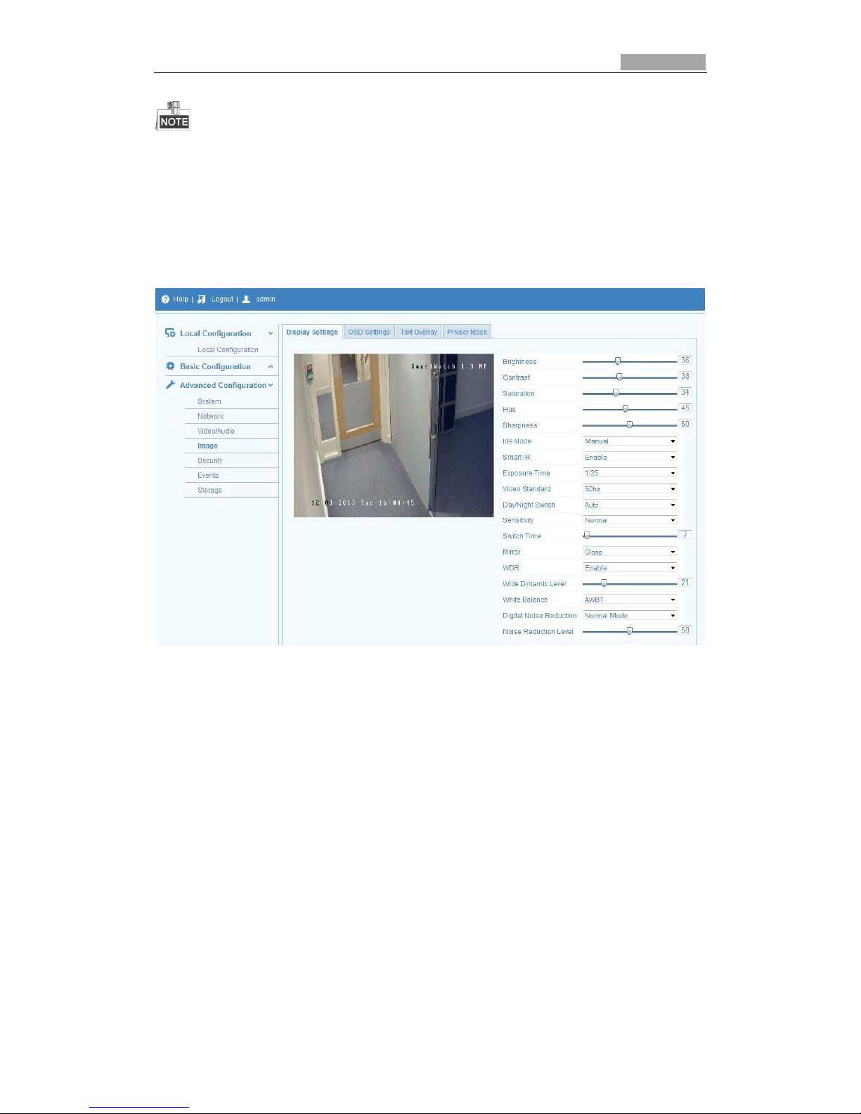
You can configure the image quality of the camera, including brightness, contrast,
saturation, hue, sharpness, etc.
Page 38
SmartWatch® IP Network Camera User Manual
38 38
The Display parameters vary depending on the camera model.
Steps:
1. Enter the Display Settings interface:
Configuration > Basic Configuration> Image> Display Settings
Or Configuration > Advanced Configuration> Image> Display Settings
2. Set the image parameters of the camera.
Figure 5-21 Display Settings
Descriptions of parameter configuration
Iris Mode:
Auto and Manual are selectable.
Auto Iris Level:
If you select auto iris mode, you can set the auto iris level.
Video Standard:
50 Hz and 60 Hz are selectable. Choose according to the different video standards;
normally 50Hz for PAL standard and 60Hz for NTSC standard.
Day/Night Switch:
Day, Night and Auto are selectable.
Sensitivity:
If you select auto day/night switch, you can set the sensitivity of the switch as high,
normal and low.
Mirror:
The mirror function enables you to view another aspect of the image. You can flip the
Page 39
SmartWatch® IP Network Camera User Manual
39 39
image horizontally and vertically. It can be used to view the image in the way you see
it directly using your eyes.
WDR:
Wide dynamic range can be used when there is a high contrast of the bright area and
the dark area of the scene.
BLC Area:
BLC area is the area sense the light intensity; Close, Up, Down, Left, Right and Center
are selectable.
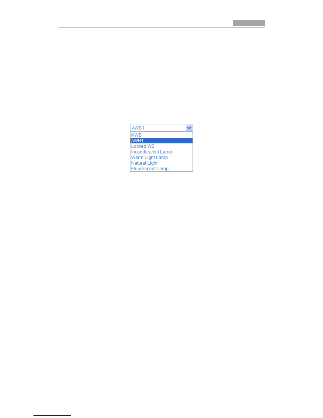
White Balance: The below figure shows the white balance options. You can select
according to the camera conditions. For example, if there is a fluorescent lamp in the
scene, select Fluorescent Lamp.
Figure 5-22 White Balance
Digital Noise Reduction:
Close, Normal Mode and Expert Mode are selectable.
Noise Reduction Level:
For adjusting the noise reduction level (only valid when the DNR function is enabled).
Scene Mode:
Select it as indoor or outdoor.
HLC:
High light function can be used when there are strong lights in the scene which affect
the image quality.
Grey Scale:
Select the range of the grey scale as [0-255] or [16-235].
Corridor mode:
To make a complete use of the 16:9 aspect ratio, you can enable corridor mode when
the camera is installed in a narrow position.
When installing, turn the camera to the 90 degrees or rotate the 3-axis lens to 90
degrees, and set the corridor mode as on, you will get a normal view of the scene
with 9:16 aspect ratio to ignore the needless information such as the wall, and get
more meaningful image.
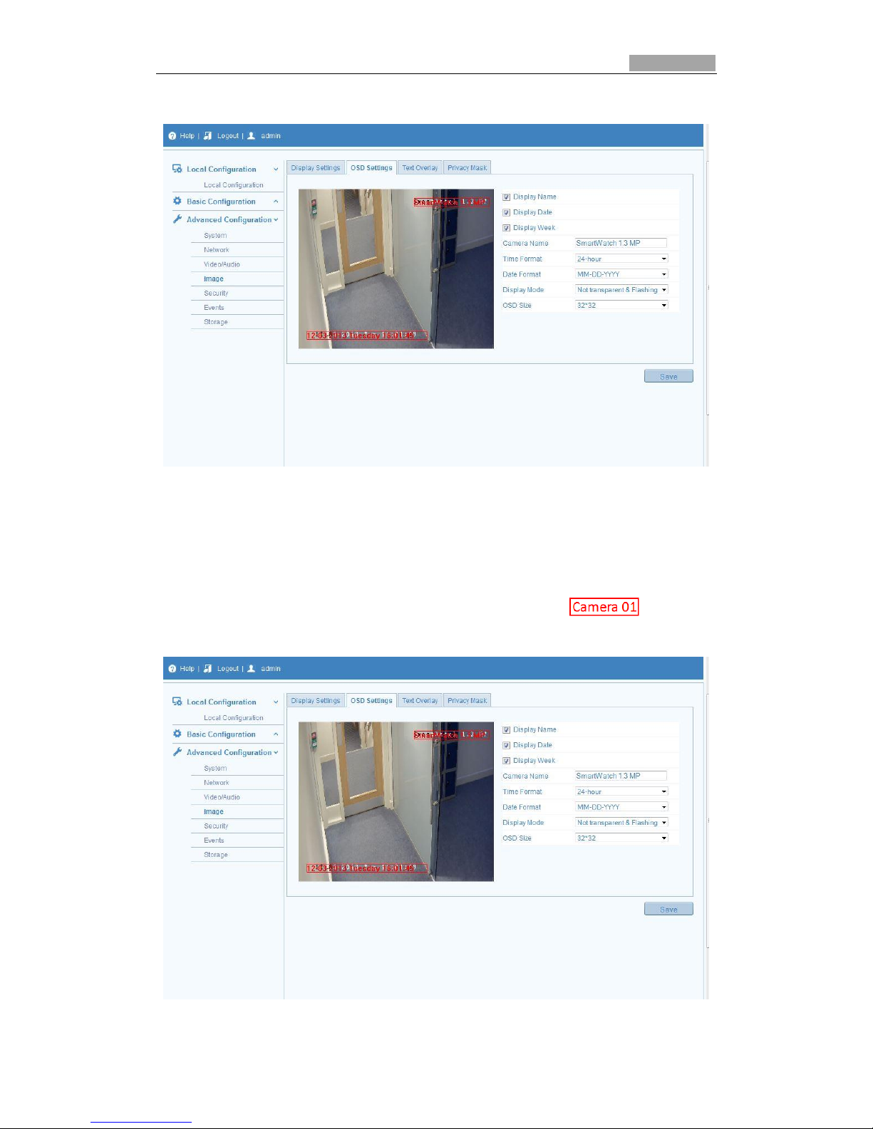
5.5.2 Configuring OSD Settings
Configure the camera’s name and time position on the screen.
Steps:
1. Enter the OSD Settings interface:
Page 40
SmartWatch® IP Network Camera User Manual
40 40
Configuration > Advanced Configuration > Image > OSD Settings
Figure 5-23 OSD Settings
2. Check the checkbox of what you want to display on the camera image.
3. Edit the camera name in the text box.
4. Select from the drop-down list to set the time format, date format, display mode
and the OSD font size.
5. You can use the mouse to click and drag the text frame in the live
view window to adjust the OSD position.
Figure 5-24 Adjust OSD Location
Page 41
SmartWatch® IP Network Camera User Manual
41 41
6. Click to activate above settings.
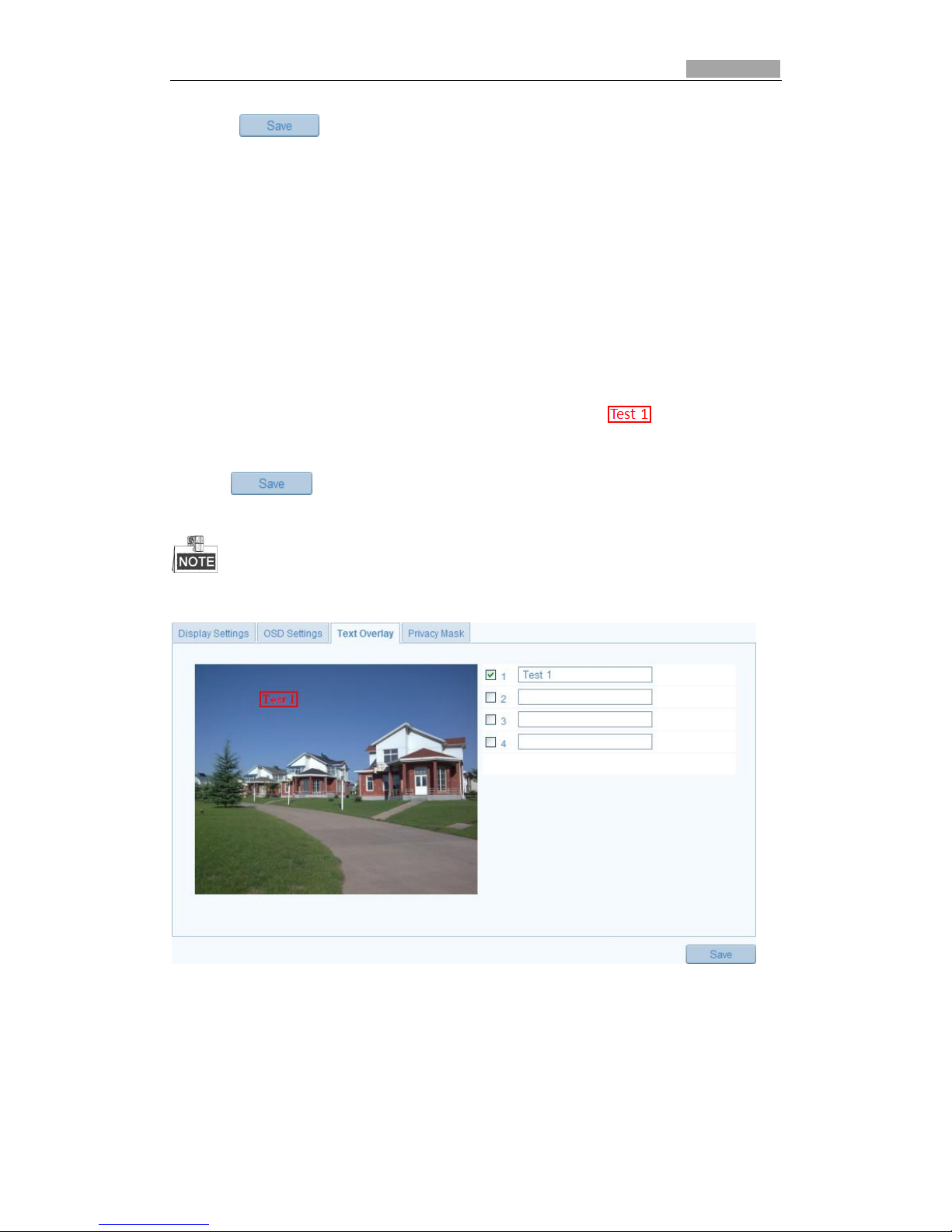
5.5.3 Configuring Text Overlay Settings
You can customize the text overlay.
Steps:
1. Enter the Text Overlay Settings:
Configuration > Advanced Configuration > Image > Text Overlay
2. Check the checkbox to enable the on-screen display.
3. Input the characters in the textbox.
4. Use the mouse to click and drag the red text frame in the live view
window to adjust the text overlay position.
5. Click .
Configure up to 4 text overlays.
Figure 5-25 Text Overlay Settings
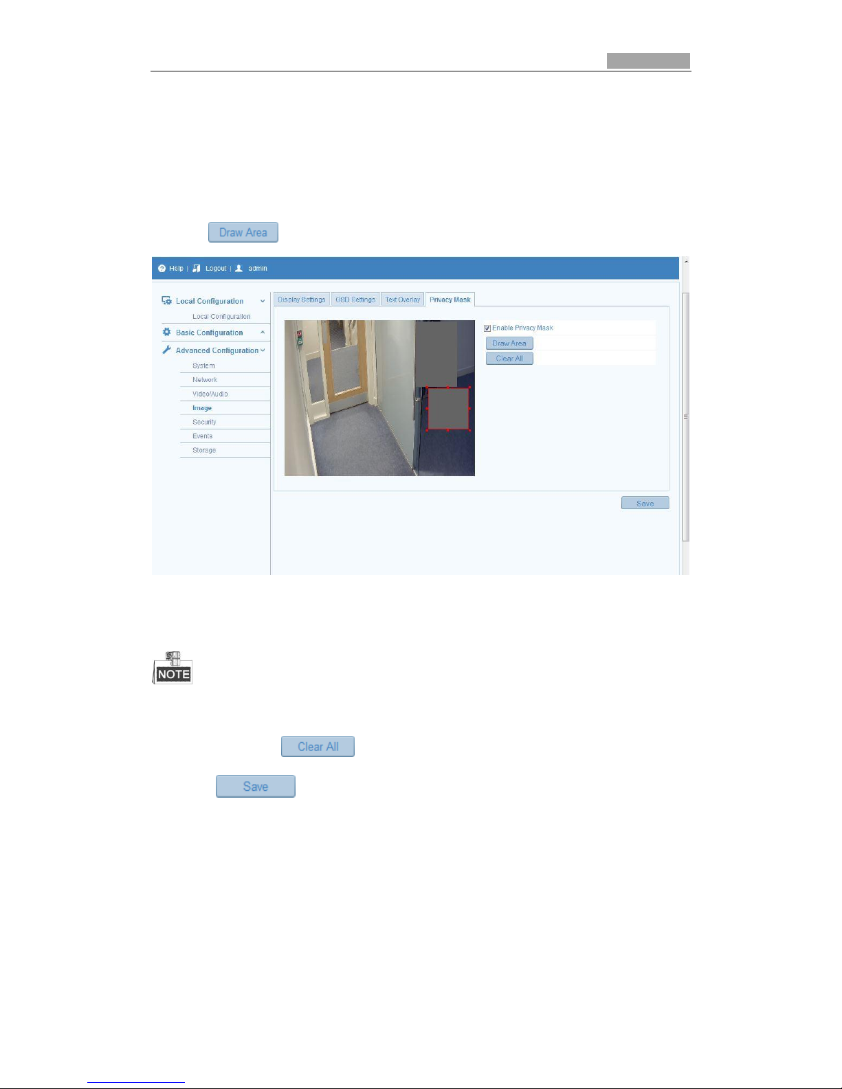
5.5.4 Configuring Privacy Mask
Privacy mask enables you to mask certain areas on scene to prevent certain them
Page 42
SmartWatch® IP Network Camera User Manual
42 42
from live view and record.
Steps:
1. Enter the Privacy Mask Settings interface:
Configuration > Advanced Configuration> Image > Privacy Mask
2. Check the checkbox to Enable Privacy Mask.
3. Click .
Figure 5-26 Privacy Mask Settings
4. Click and drag the mouse draw the mask area.
Draw up to 4 areas per camera.
5. (Optional) click to clear all of the areas you set.
6. Click to save the settings.
5.6 Configuring and Handling Alarms
This section explains how to configure the IP network camera to respond to alarm
events, including motion detection, tamper-proof, alarm input, alarm output and
other exceptions. These events can trigger alarm actions, such as Notify Surveillance
Center, Send Email, Trigger Alarm Output, etc.
For example, when an external alarm is triggered, the IP network camera sends a
Page 43
SmartWatch® IP Network Camera User Manual
43 43
notification to an e-mail address.
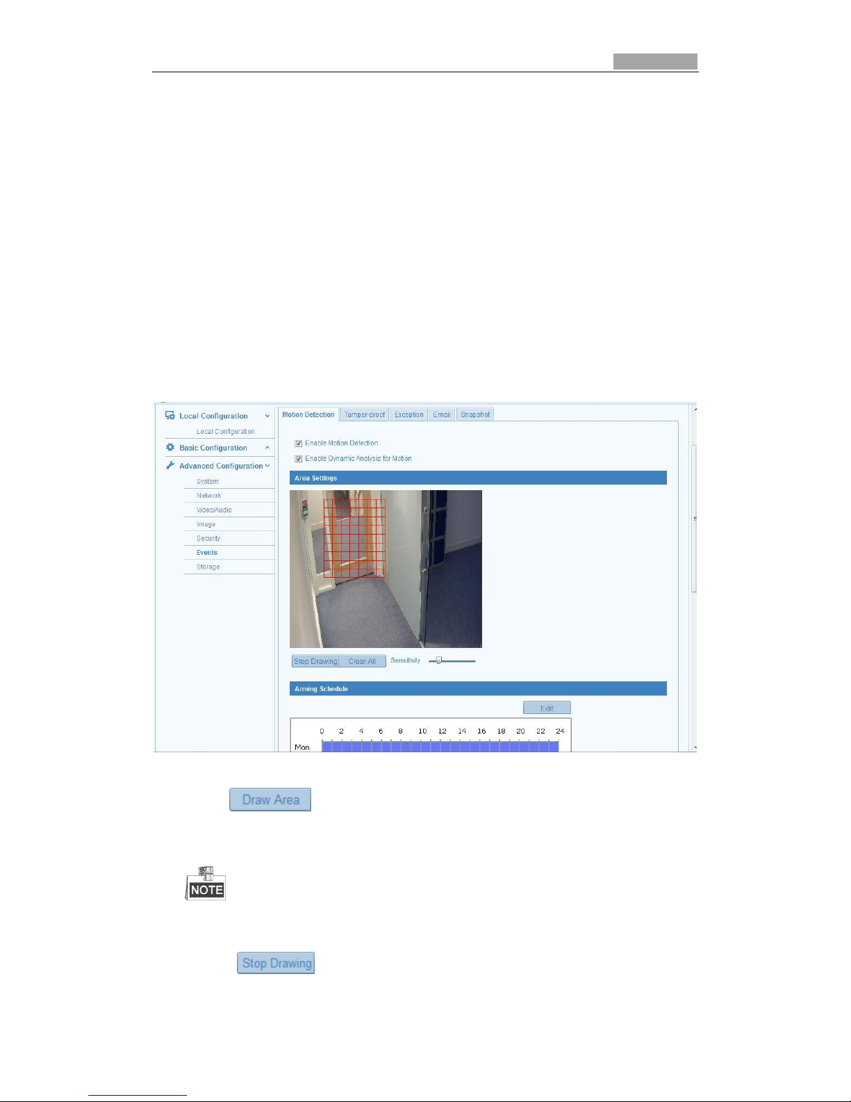
5.6.1 Configuring Motion Detection
Motion detection is a feature that can take alarm activities and record the video from
when the motion occurred in the surveillance scene.
Tasks:
1. Set the Motion Detection Area.
Steps:
(1) Enter the motion detection settings interface
Configuration > Advanced Configuration> Events > Motion Detection
(2) Check the checkbox of Enable Motion Detection.
Figure 5-27 Enable Motion Detection
(3) Click . Click and drag the mouse on the live video image to draw a
motion detection area.
You can draw up to 8 motion detection areas on the same camera.
(4) Click to finish drawing.
Page 44
SmartWatch® IP Network Camera User Manual
44 44
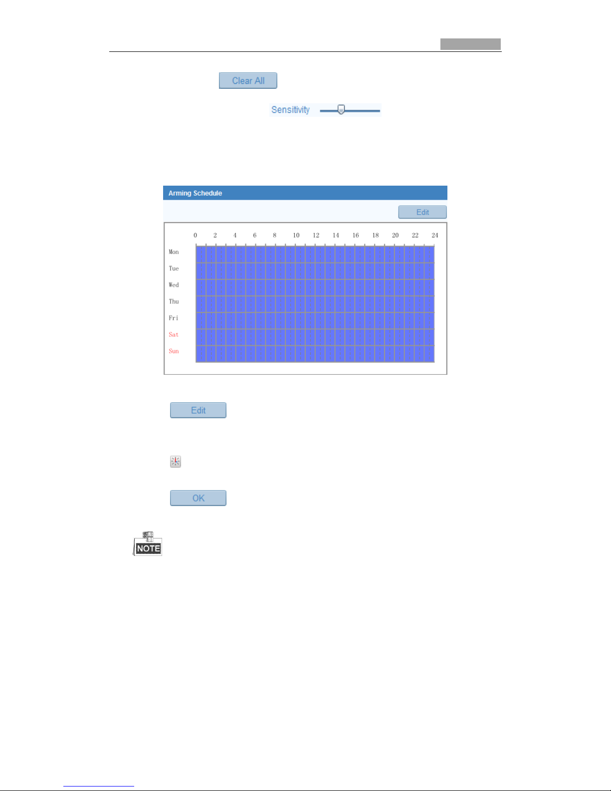
(5) (Optional) Click to clear all of the areas.
(6) (Optional) Move the slider to set the sensitivity of
the detection areas.
2. Set the Arming Schedule for Motion Detection.
Steps:
Figure 5-28 Arming Time
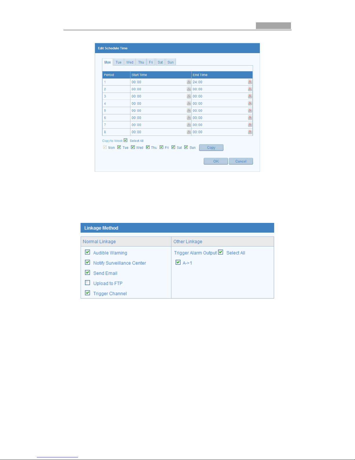
(1) Click to edit the arming schedule. The Figure 5-29 shows the
editing interface of the arming schedule.
(2) Select the day you want to set the arming schedule.
(3) Click to set the time period for the arming schedule.
(4) After you set the arming schedule, you can copy the schedule to other days.
(5) Click to save the settings.
Up to 4 time periods can be configured per day.
Page 45
SmartWatch® IP Network Camera User Manual
45 45
Figure 5-29 Arming Time Schedule
3. Set the Alarm Actions for Motion Detection.
You can specify the linkage method when an event occurs. The following
contents are about how to configure the different types of linkage method.
Figure 5-30 Linkage Method
Steps:
(1) Check the checkbox to select the linkage method. Audible warning, notify
surveillance center, send email, upload to FTP, trigger channel and trigger
alarm output are selectable (Optional).
Audible Warning
Trigger the audible warning locally.
Notify Surveillance Center
Send an exception or alarm signal to remote management software when
an event occurs.
Send Email
Send an email with alarm information to a user or users when an event
occurs.
Page 46

SmartWatch® IP Network Camera User Manual
46 46
To send the Email when an event occurs, you will need to refer to Section 5.6.6 to
set the related parameters.
Upload to FTP
Capture the image when an alarm is triggered and upload the image to a
FTP server.
Set the FTP address and the remote FTP server first. Refer to Section 5.3.8 for
detailed information.
Trigger Channel
The video will be recorded when the motion is detected. You have to set the
recording schedule for this function. Please refer to Section 6.2 for detailed
information.
Trigger Alarm Output
Trigger one or more external alarm outputs when an event occurs.
To trigger an alarm output when an event occurs, please refer to Section 5.6.4 to
set the related parameters.
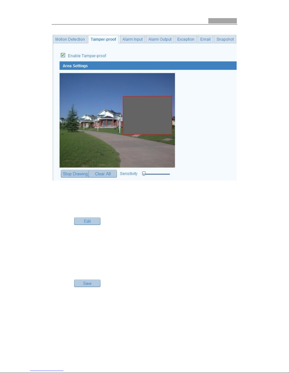
5.6.2 Configuring Tamper-proof Alarm
You can configure the camera to trigger an alarm when the lens is covered.
Steps:
1. Enter the Tamper-proof Settings interface:
Configuration > Advanced Configuration > Events > Tamper-proof
Page 47
SmartWatch® IP Network Camera User Manual
47 47
Figure 5-31 Tamper-proof Alarm
2. Check Enable Tamper-proof checkbox to enable tamper-proof detection.
3. Set the tamper-proof area; refer to Step 1 Set the Motion Detection Area in
Section 5.6.1.
4. Click to edit the arming schedule for tamper-proof detection. The
arming schedule configuration is the same as setting the arming schedule for motion
detection. Refer to Step 2 Set the Arming Schedule for Motion Detection in Section
5.6.1.
5. Check the checkbox to select the linkage method for tamper-proof. Audible
warning, notify surveillance center, send email and trigger alarm output are
selectable. Please refer to Step 3 Set the Alarm Actions for Motion Detection in
Section 5.6.1.
6. Click to save the settings.
5.6.3 Configuring External Alarm Input
1. Enter the Alarm Input Settings interface:
Configuration > Advanced Configuration> Events > Alarm Input:
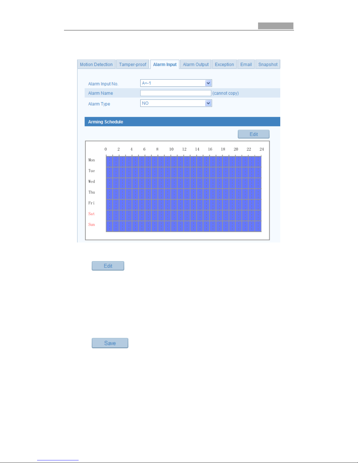
2. Select the alarm input No. and the Alarm Type. The alarm type can be NO
Page 48
SmartWatch® IP Network Camera User Manual
48 48
(Normally Open) and NC (Normally Closed). Edit the name for the alarm input
(optional).
Figure 5-32 Alarm Input Settings
3. Click to set the arming schedule for the alarm input. Refer to Step 2
Set the Arming Schedule for Motion Detection in Section 5.6.1.
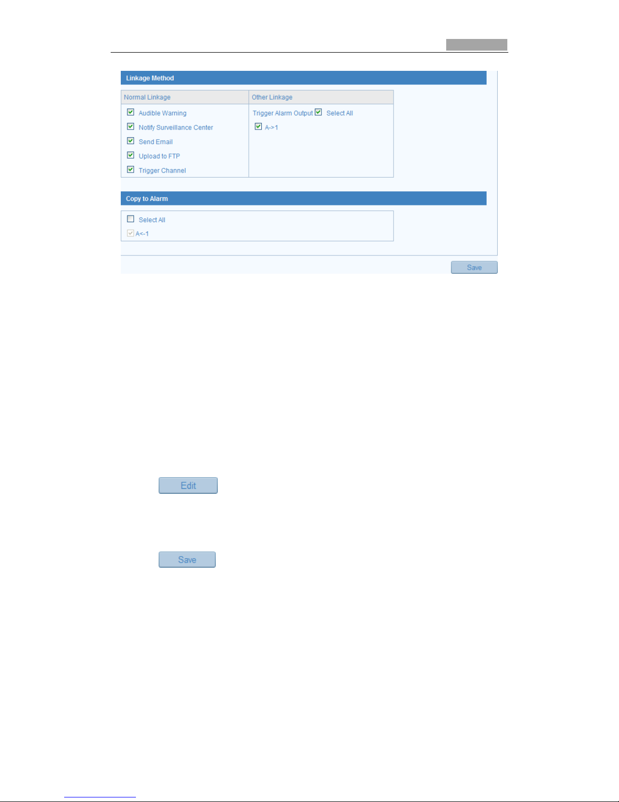
4. Check the checkbox to select the linkage method taken for the alarm input. Refer
to Step 3 Set the Alarm Actions for Motion Detection in Section 5.6.1.
5. You can also select PTZ linking for the alarm input if PTZ cameras are installed.
Check the relative checkbox and select the No. to enable Preset Calling, Patrol
Calling or Pattern Calling.
6. You can copy your settings to other alarm inputs.
7. Click to save the settings.
Page 49
SmartWatch® IP Network Camera User Manual
49 49
Figure 5-33 Linkage Method
5.6.4 Configuring Alarm Output
Steps:
1. Enter the Alarm Output Settings interface:
Configuration>Advanced Configuration> Events > Alarm Output
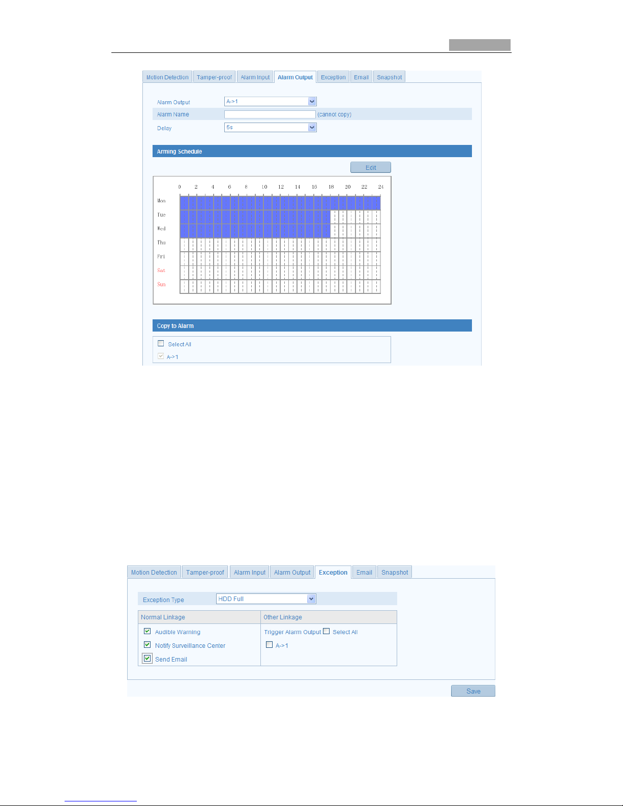
2. Select one alarm output channel in the Alarm Output drop-down list. Configure
a name for the alarm output (optional).
3. The Delay time can be set to 5sec, 10sec, 30sec, 1min, 2min, 5min, 10min or
Manual. The delay time refers to the time duration that the alarm output remains
after alarm occurs.
4. Click to enter the Edit Schedule Time interface. The time schedule
configuration is the same as the settings of the arming schedule for motion detection
Refer to Step 2 Set the Arming Schedule for Motion Detection in Section 5.6.1.
5. You can copy the settings to other alarm outputs.
6. Click to save the settings.
Page 50
SmartWatch® IP Network Camera User Manual
50 50
Figure 5-34 Alarm Output Settings
5.6.5 Handling Exception
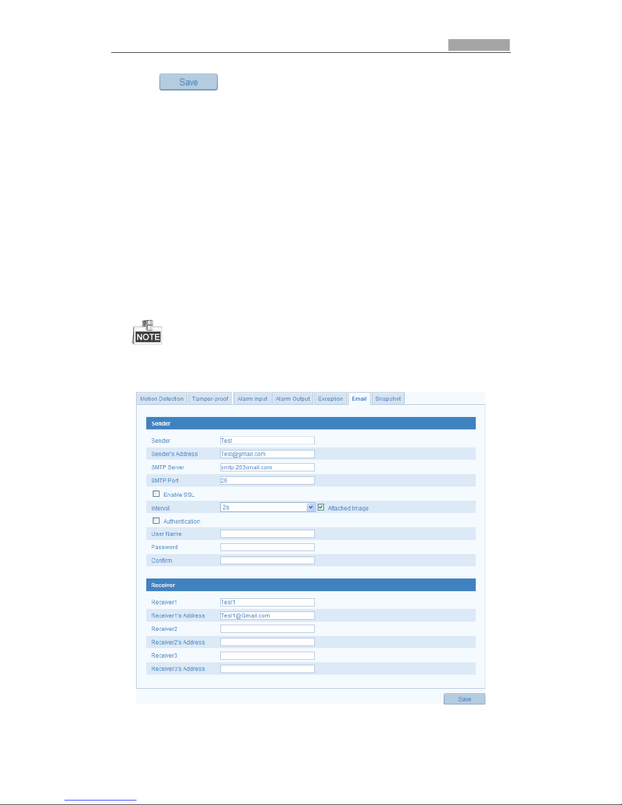
Other exceptions can be HDD full, HDD error, network disconnected, IP address
conflicted and illegal login to the cameras.
Steps:
1. Enter the Exception Settings interface:
Configuration > Advanced Configuration> Events > Exception
2. Check the checkbox to set the actions taken for the Exception alarm. Refer to
Step 3 Set the Alarm Actions Taken for Motion Detection in Section 5.6.1.
Figure 5-35 Exception Settings
Page 51
SmartWatch® IP Network Camera User Manual
51 51
3. Click to save the settings.
5.6.6 Email Sending Triggered by Alarm
The system can be configured to send an Email notification to all addresses if an
alarm event is detected, e.g., motion detection event, video loss, tamper, etc.
Before you start:
Please configure the DNS Server settings under Basic Configuration > Network >
TCP/IP or Advanced Configuration > Network > TCP/IP before using the Email
function.
Steps:
1. Enter the TCP/IP Settings (Configuration > Basic Configuration > Network > TCP/IP or
Configuration > Advanced Configuration > Network > TCP/IP) to set the IPv4
Address, IPv4 Subnet Mask, IPv4 Default Gateway and the Preferred DNS Server.
Please refer to Section 5.3.1 Configuring TCP/IP Settings for detailed information.
2. Enter the Email Settings interface:
Configuration > Advanced Configuration > Events > Email
Figure 5-36 Email Settings
Page 52

SmartWatch® IP Network Camera User Manual
52 52
3. Configure the following settings:
Sender: The name of the email sender.
Sender’s Address: The email address of the sender.
SMTP Server: The SMTP Server IP address or host name (e.g.,
smtp.263xmail.com).
SMTP Port: The SMTP port. The default TCP/IP port for SMTP is 25 (not secured).
And the SSL SMTP port is 465.
Enable SSL: Check the checkbox to enable SSL if it is required by the SMTP
server.
Attached Image: Check the checkbox of Attached Image if you want to send
emails with attached alarm images.
Interval: The interval refers to the time between two actions of sending attached
images.
Authentication (optional): If your email server requires authentication, check
this checkbox to use authentication to log in to this server and enter the login
user Name and password.
Choose Receiver: Select the receiver to which the email is sent. Up to 2 receivers
can be configured.
Receiver: The name of the user to be notified.
Receiver’s Address: The email address of user to be notified.
4. Click to save the settings.
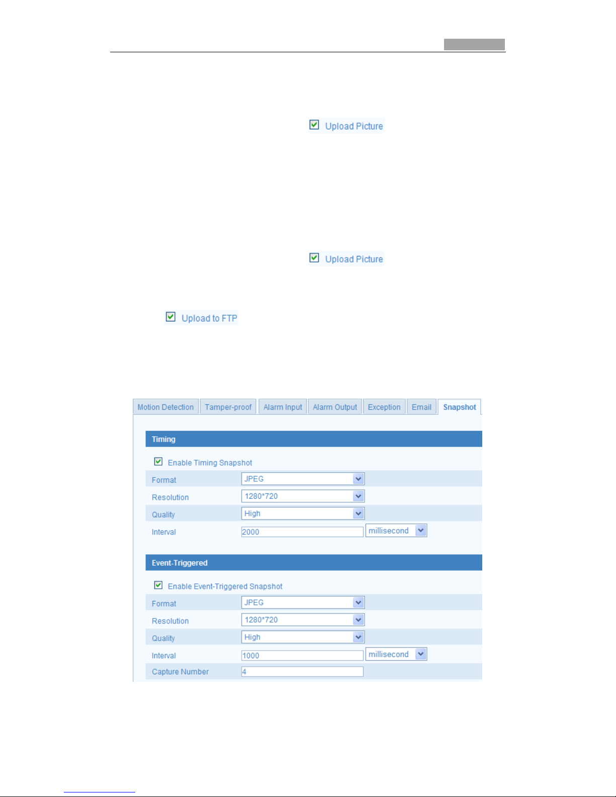
5.6.7 Configuring Snapshot Settings
You can configure a scheduled snapshot or an event-triggered snapshot. The
captured image can be stored on the SD card (if supported by camera) or upload to a
FTP server.
Basic Settings
Steps:
1. Enter the Snapshot Settings interface:
Configuration > Advanced Configuration > Events > Snapshot
2. Check the Enable Timing Snapshot checkbox to enable continuous snapshot.
Check the Enable Event-triggered Snapshot checkbox to check event-triggered
snapshot.
3. Select the quality of the snapshot.
4. Set the time interval between two snapshots.
5. Click to save the settings.
Uploading to FTP
You can follow below configuration instructions to upload the snapshots to FTP.
Page 53
SmartWatch® IP Network Camera User Manual
53 53
Upload continuous snapshots to FTP
Steps:
1) Configure the FTP settings and check checkbox in FTP Settings
interface. Please refer to Section 5.3.8 Configuring FTP Settings for more details
to configure FTP parameters.
2) Check the Enable Timing Snapshot checkbox.
Upload event-triggered snapshots to FTP
Steps:
1) Configure the FTP settings and check checkbox in FTP Settings
interface. Please refer to Section 5.3.8 Configuring FTP Settings for more details
to configure FTP parameters.
2) Check checkbox in Motion Detection Settings or Alarm Input
interface. Please refer to Step 3 Set the Alarm Actions Taken for Motion
Detection in Section 6.6.1, or Step 4 Configuring External Alarm Input in Section
5.6.3.
3) Check the Enable Event-triggered Snapshot checkbox.
Figure 5-37 Snapshot Settings
Page 54
SmartWatch® IP Network Camera User Manual
54
Chapter 6 Storage Settings
Before you start:
To configure record settings, please make sure that you have the network storage
device on the network or an SD card inserted in your camera.
6.1 Configuring NAS Settings
Before you start:
The network disk should be available on the network and properly configured to
store the recorded files, log files, etc.
Steps:
1. Add the network disk
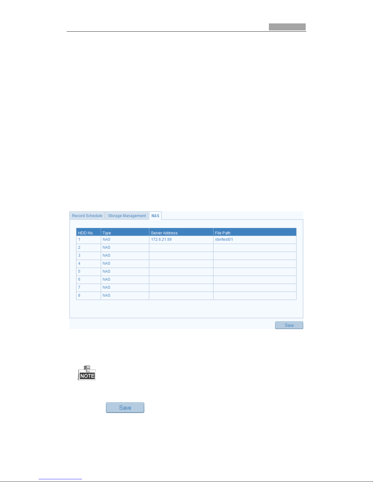
(1) Enter the NAS (Network-Attached Storage) Settings interface:
Configuration > Advanced Configuration > Storage > NAS
Figure 6-1 Add Network Disk
(2) Enter the IP address of the network disk, and enter the default file path.
Please refer to the User Manual of NAS for creating the file path.
(3) Click to add the network disk.
Page 55
SmartWatch® IP Network Camera User Manual
55 55
After having saved successfully, you need to reboot the camera to activate the settings.
2. Initialize the added network disk.
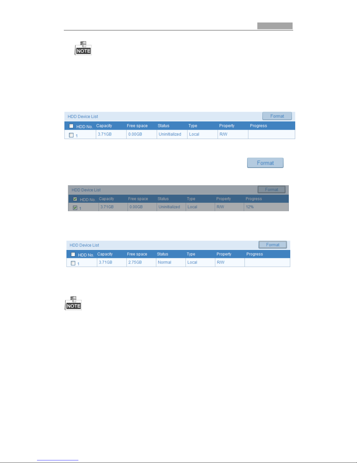
(1) Enter the HDD Settings interface (Advanced Configuration > Storage >
Storage Management), in which you can view the capacity, free space, status,
type and property of the disk.
Figure 6-2 Initialize Disk
(2) If the status disk is Uninitialized select the disk and click to
start initializing the disk.
Figure 6-3 Initializing
When the initialization completed, the status of disk will become Normal.
Figure 6-4 View Disk Status
Up to 8 NAS disks can be connected to the camera.
To initialize and use the SD card after insert it to the camera, please refer to the steps of
NAS disk initialization.
6.2 Configuring Recording Schedule
There are two types of recording settings for the cameras: manual recording and
scheduled recording. For manual recording, refer to Section 4.3 Recording and
Capturing Images Manually. In this section, you can follow the instructions to
configure the scheduled recording.
Steps:
Page 56
SmartWatch® IP Network Camera User Manual
56 56
1. Enter the Record Schedule Settings interface:
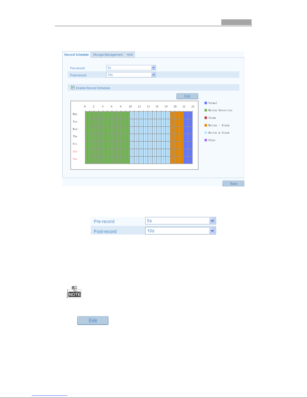
Configuration > Advanced Configuration> Storage > Record Schedule
Figure 6-5 Recording Schedule Interface
2. Check to Enable Record Schedule.
3. Set the record parameters of the camera.
Figure 6-6 Record Parameters
Pre-record: The time you set to start recording before the scheduled time or
before an event.
Post-record: The time you set to stop recording after the scheduled time or
an event.
The record parameter configurations vary depending on the camera model.
4. Click to edit the record schedule.
Page 57
SmartWatch® IP Network Camera User Manual
57 57
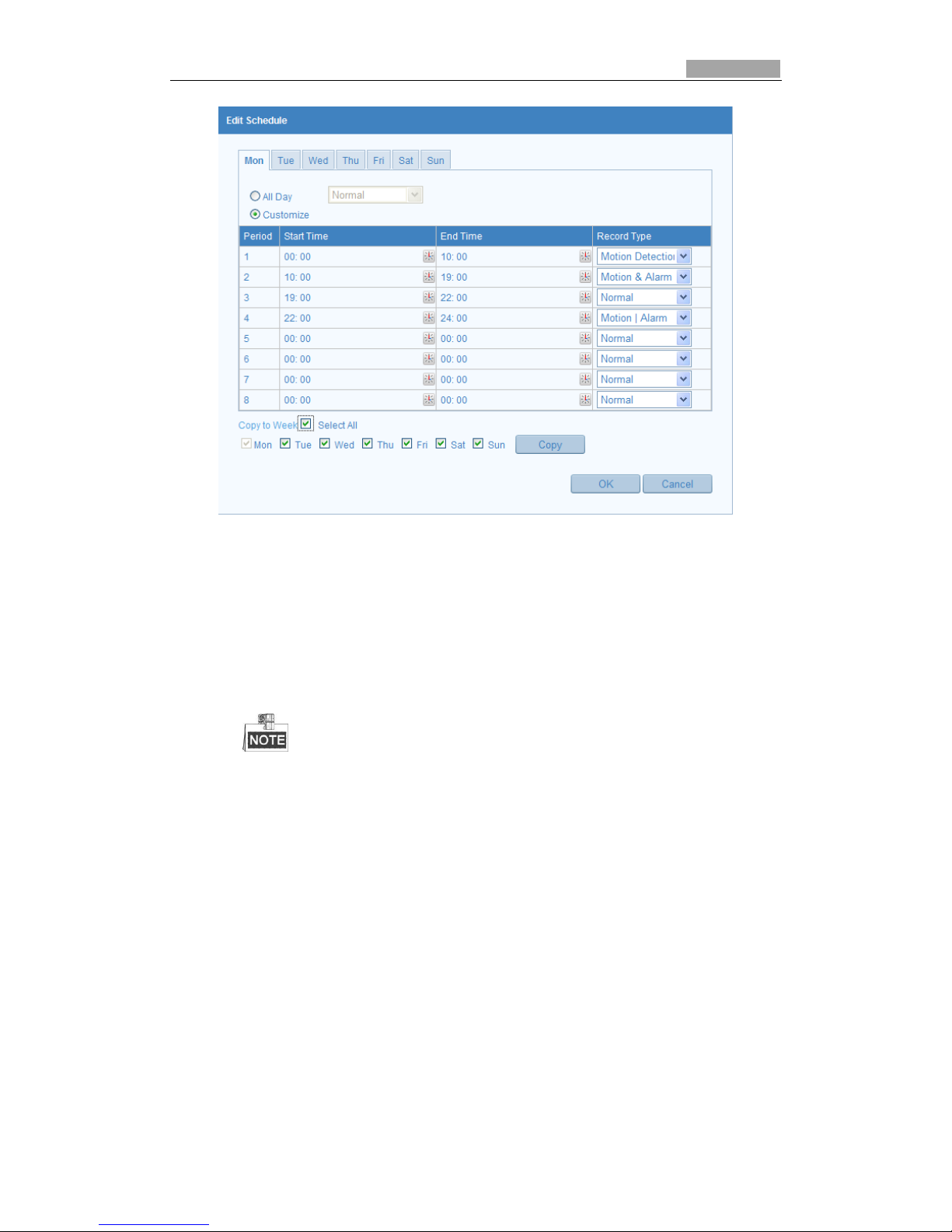
Figure 6-7 Record Schedule
5. Select the day to set the record schedule.
(1) Set all-day record or segment record:
If you want to configure the all-day recording, please select the All Day
checkbox.
If you want to record in different time schedules, select Customize checkbox.
Set Start Time and End Time.
The time of each segment cannot be overlapped. Up to 4 segments can be
configured.
(2) Select a Record Type. The record type can be Normal, Motion Detection,
Alarm or Motion Alarm.
Normal
If you select Normal, recording will be as per motion alarm time schedule.
Record Triggered by Motion Detection
If you select Motion Detection, the video will be recorded when the motion
is detected.
Record Triggered by Alarm
If you select Alarm, the video will be recorded when the alarm input is
triggered.
Record Triggered by Motion & Alarm
If you select Motion & Alarm, the video will be recorded when the motion
and alarm input is triggered at the same time.
Page 58
SmartWatch® IP Network Camera User Manual
58 58
Record Triggered by Motion | Alarm
If you select Motion | Alarm, the video will be recorded when the external
alarm is triggered or motion is detected.
(3) Check the checkbox and click to copy settings of
this day to the whole week. You can also check any of the checkboxes before
the date and click .
(4) Click to save the settings and exit the Edit Record Schedule
interface.
6. Click to save the settings.
Page 59
SmartWatch® IP Network Camera User Manual
59
Chapter 7 Playback
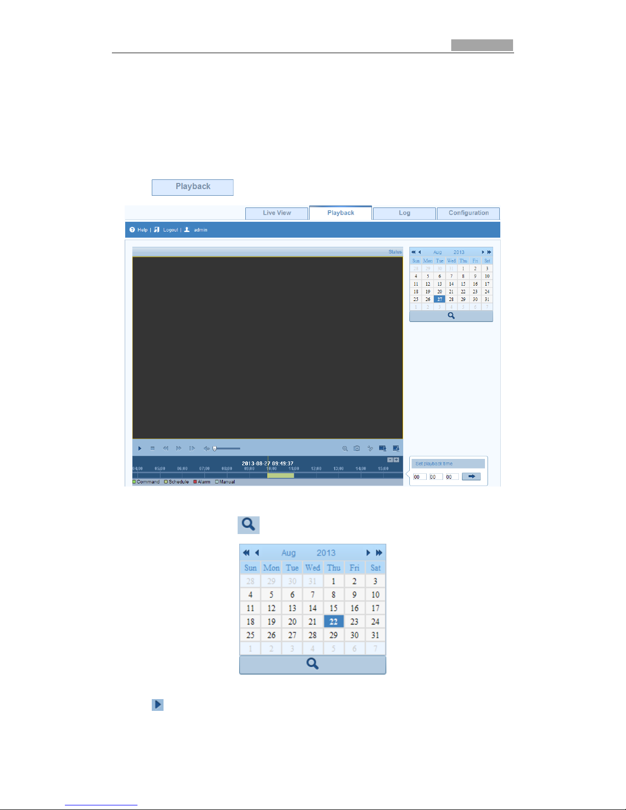
This section explains how to view remote recorded video files stored on the network
or SD cards.
Steps:
1. Click on the menu bar to enter playback screen.
Figure 7-1 Playback Interface
2. Select the date and click .
Figure 7-2 Search Video
3. Click to play the video files found on this date.
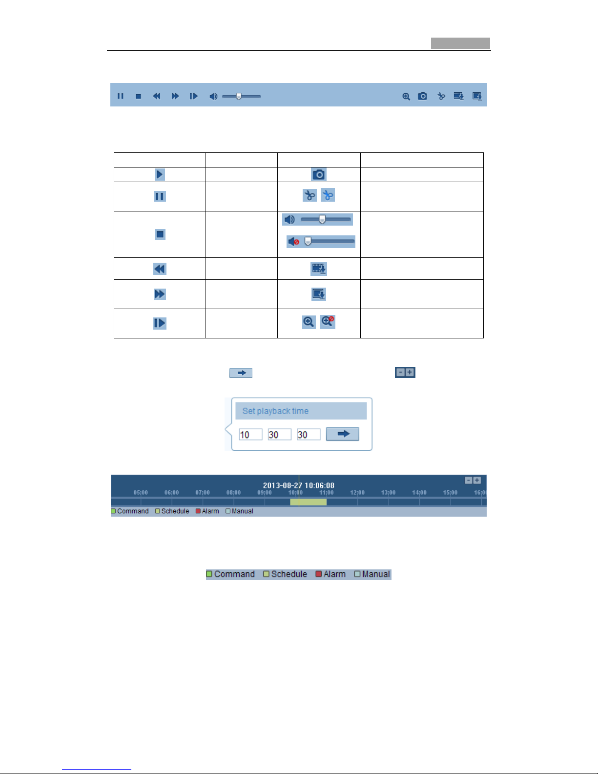
The toolbar on the bottom of Playback screen can be used to control playback
Page 60
SmartWatch® IP Network Camera User Manual
60 60
process.
Figure 7-3 Playback Toolbar
Table 7-1 Description of the buttons
Button
Operation
Button
Operation
Play
Capture a image
Pause
/
Start/Stop clipping video
files
Stop
/
Audio on and adjust
volume/Mute
Speed down
Download video files
Speed up
Download captured
images
Playback by
frame
/
Enable/Disable digital
zoom
Drag the progress bar with the mouse to go to a different playback position. You can
also input a time and click to go to a required time. Click to zoom out/in
the progress bar.
Figure 7-4 Set Playback Time
Figure 7-5 Progress Bar
The different colors of the video on the progress bar stand for the different video
types.
Figure 7-6 Video Types
Page 61
SmartWatch® IP Network Camera User Manual
61
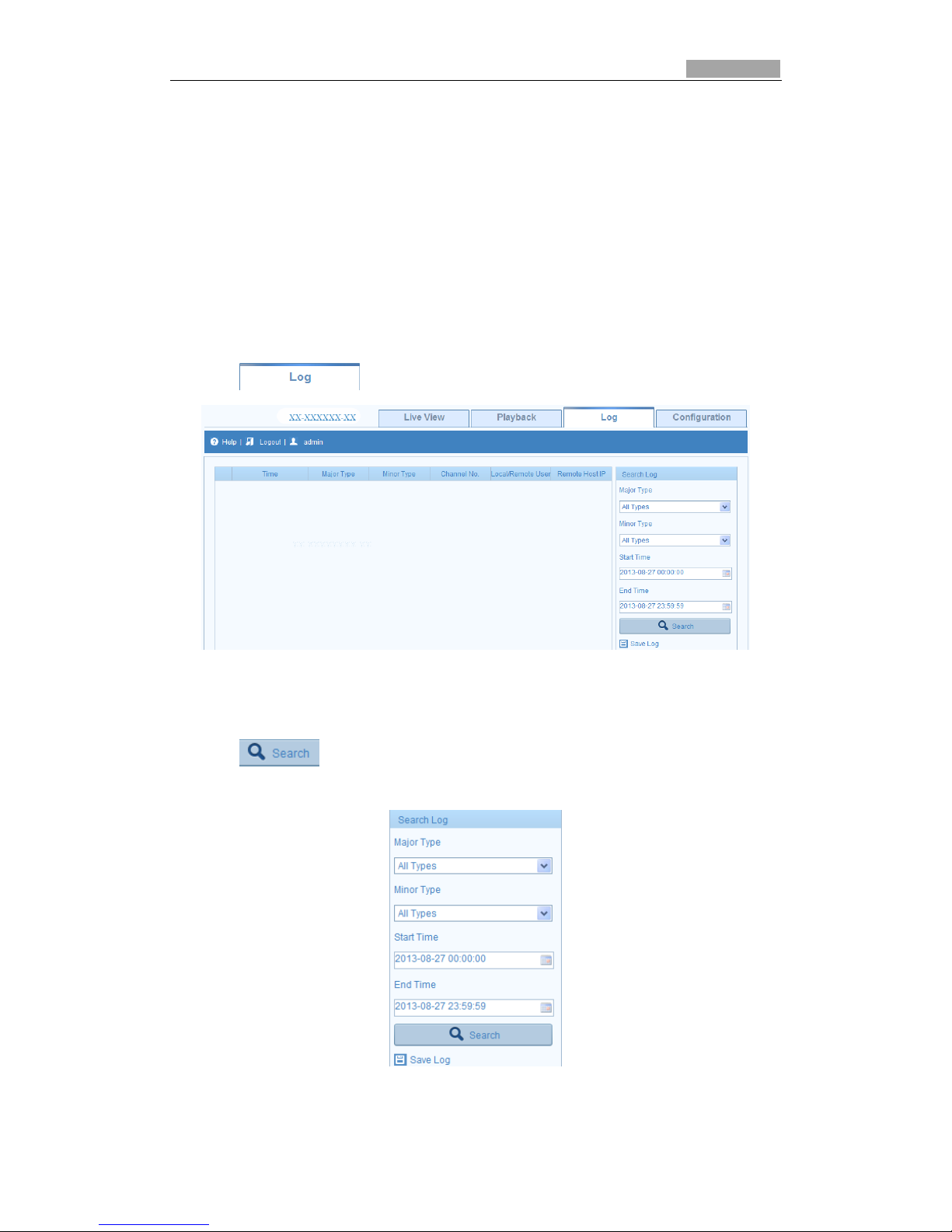
Chapter 8 Log Searching
Log information from the camera can be stored in log files. You can also export these
log files.
Before you start:
Please configure network storage or insert a SD card in the camera.
Steps:
1. Click on the menu bar to enter log searching interface.
Figure 8-1 Log Searching Interface
2. Set the log search conditions.
3. Click to search the log files. The log files will be displayed on the Log
interface.
Figure 8-2 Log Searching
Page 62

SmartWatch® IP Network Camera User Manual
62 62
4. To export the log files, click to save the log files in your computer.
Page 63
SmartWatch® IP Network Camera User Manual
63
Chapter 9 Others
9.1 Managing User Accounts
Enter the User Management interface:
Configuration >Basic Configuration> Security > User
Or Configuration > Advanced Configuration> Security > User
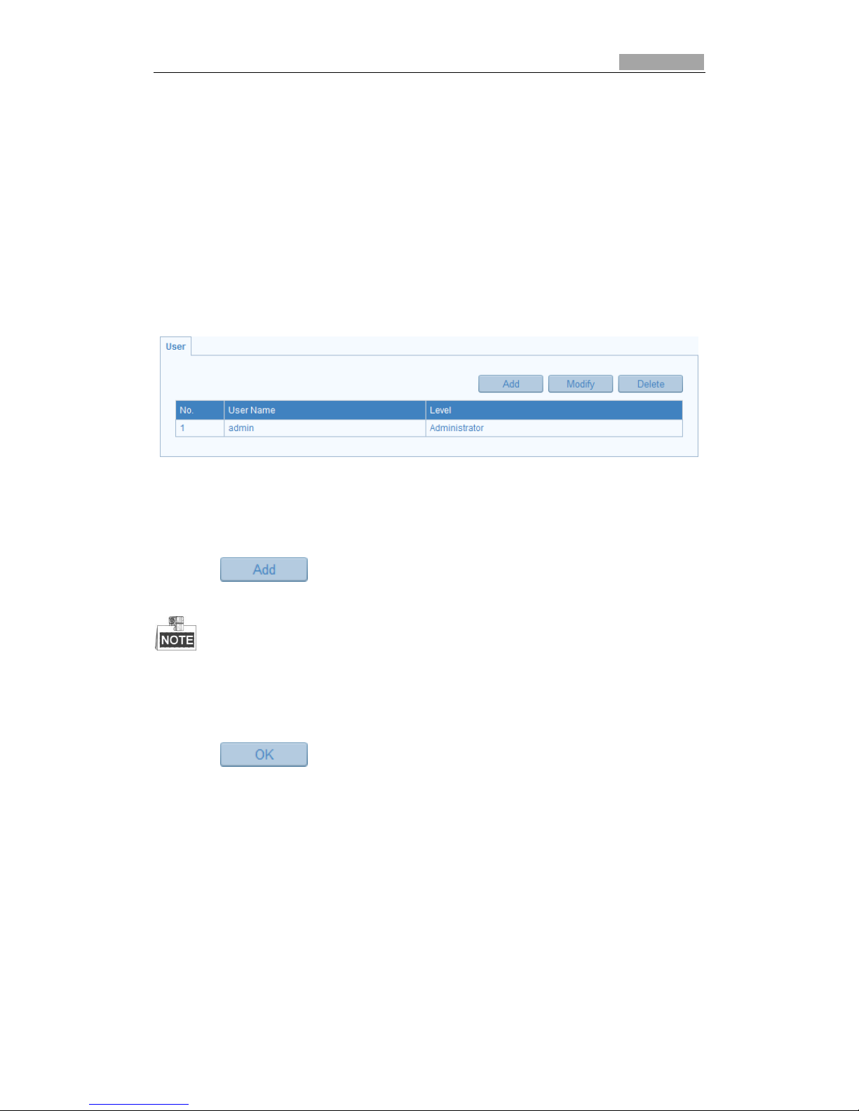
The admin user has access to create, modify or delete other accounts. Up to 15 user
accounts can be created.
Figure 9-1 User Information
Add a User
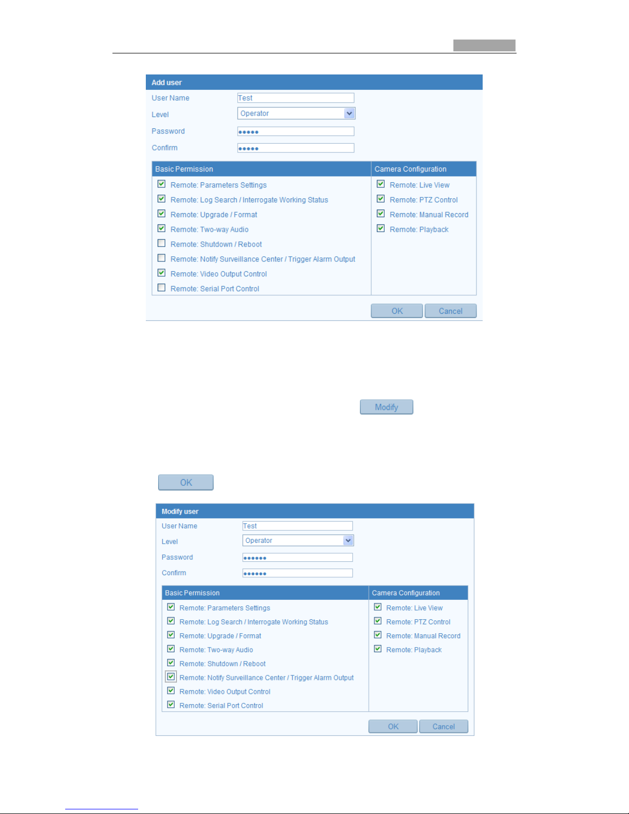
Steps:
1. Click to add a user.
2. Input the new User Name, select Level and input Password.
The level indicates the permissions you give to the user. You can define the user as Operator
or User.
3. In the Basic Permission field and Camera Configuration field, you can check or
uncheck the permissions for the new user.
4. Click to finish the user addition.
Page 64
SmartWatch® IP Network Camera User Manual
64 64
Figure 9-2 Add a User
Modify a User
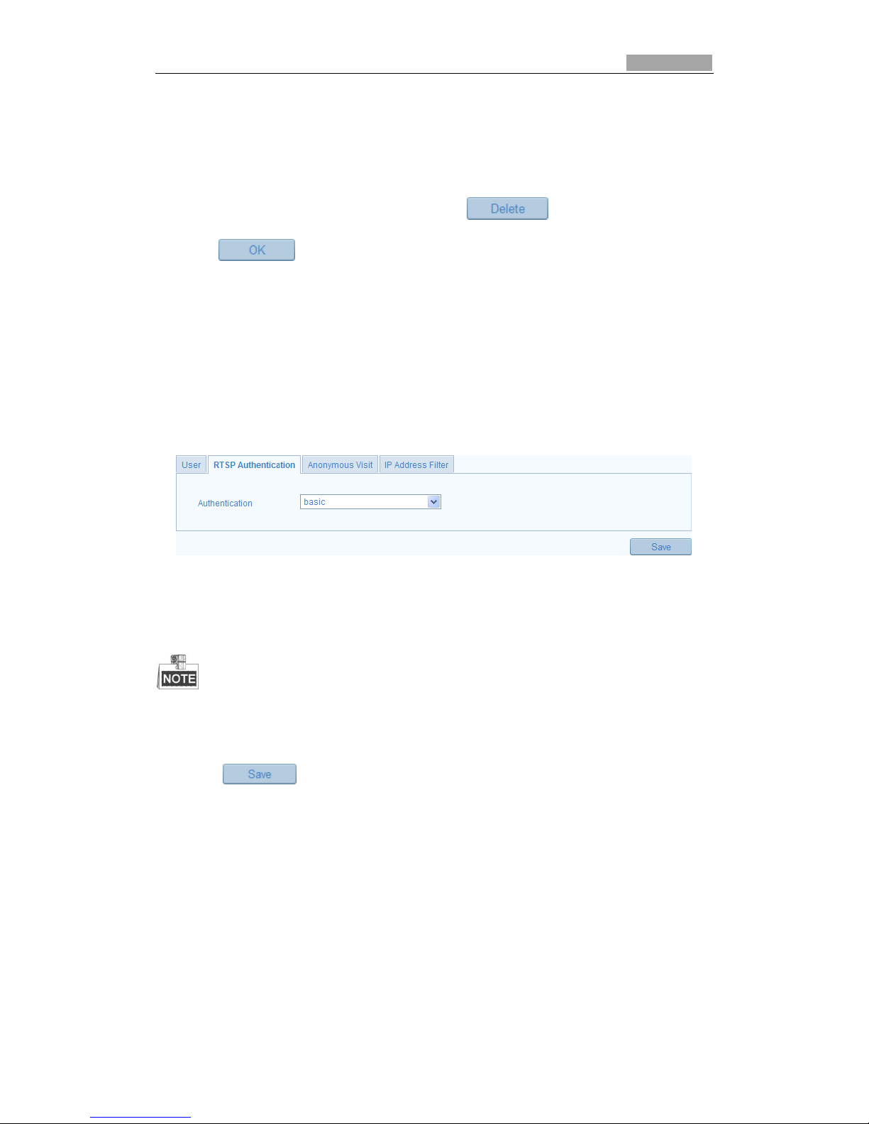
Steps:
1. Left-click to select the user from the list and click .
2. Modify the User Name, Level or Password.
3. In the Basic Permission field and Camera Configuration field, you can check or
uncheck the permissions.
4. Click to complete the users permissions.
Page 65
SmartWatch® IP Network Camera User Manual
65 65
Figure 9-3 Modify a User
Delete a User
Steps:
1. Select the user you want to delete, and click .
2. Click when dialogue box pops up to confirm the operation.
9.2 Configuring RTSP Authentication
You can specifically secure the stream data of live view.
Steps:
1. Enter the RTSP Authentication interface:
Configuration> Advanced Configuration> Security > RTSP Authentication
Figure 9-4 RTSP Authentication
2. Select the Authentication type basic or disable in the drop-down list to enable
or disable the RTSP authentication.
If you disable the RTSP authentication, anyone can access the video stream by the RTSP
protocol via the IP address.
3. Click to save the settings.
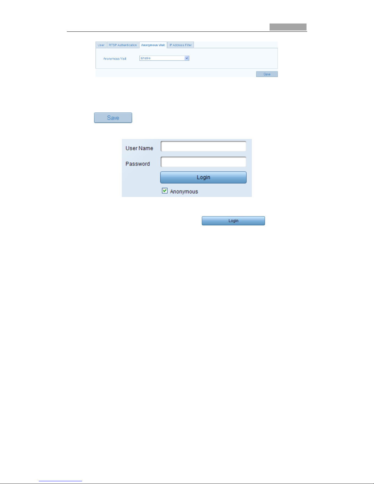
9.3 Anonymous Visit
Enabling this function allows verybody access without the user name and password
for the device.
Steps:
1. Enter the Anonymous Visit interface:
Configuration> Advanced Configuration> Security > Anonymous Visit
Page 66
SmartWatch® IP Network Camera User Manual
66 66
Figure 9-5 Anonymous Visit
2. Set the Anonymous Visit permission Enable or Disable in the drop-down list to
enable or disable anonymous visit.
3. Click to save the settings.
There will be a checkbox of Anonymous by the next time you logging in.
Figure 9-6 Login Interface with an Anonymous Checkbox
4. Check the checkbox of Anonymous and click .
9.4 IP Address Filter
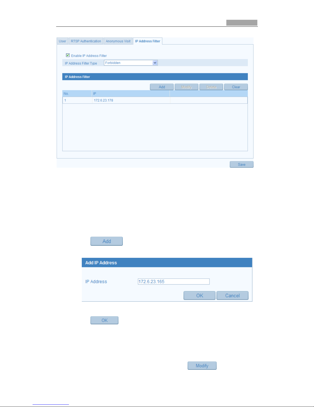
This function makes it possible for access control.
Steps:
1. Enter the IP Address Filter interface:
Configuration> Advanced Configuration> Security > IP Address Filter
Page 67
SmartWatch® IP Network Camera User Manual
67 67
Figure 9-7 IP Address Filter Interface
2. Check the checkbox of Enable IP Address Filter.
3. Select the type of IP Address Filter in the drop-down list, Forbidden or Allowed.
4. Set the IP Address Filter list.
Add an IP Address
Steps:
(1) Click to add an IP.
(2) Input the IP Adreess.
Figure 9-8 Add an IP
(3) Click to finish adding.
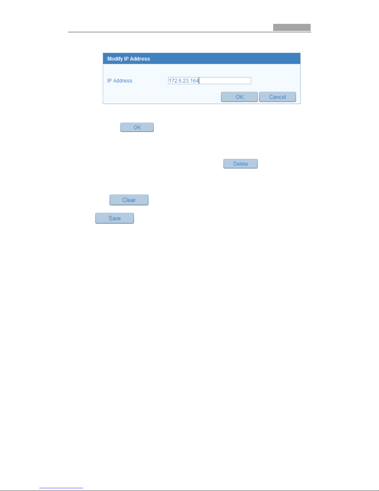
Modify an IP Address
Steps:
(1) Left-click an IP address from filter list and click button.
Page 68
SmartWatch® IP Network Camera User Manual
68 68
(2) Modify the IP address in the text filed.
Figure 9-9 Modify an IP
(3) Click the button to finish modification.
Delete an IP Address
Left-click an IP address from filter list and click .
Delete all IP Addresses
Click to delete all the IP addrsses.
5. Click to save the settings.
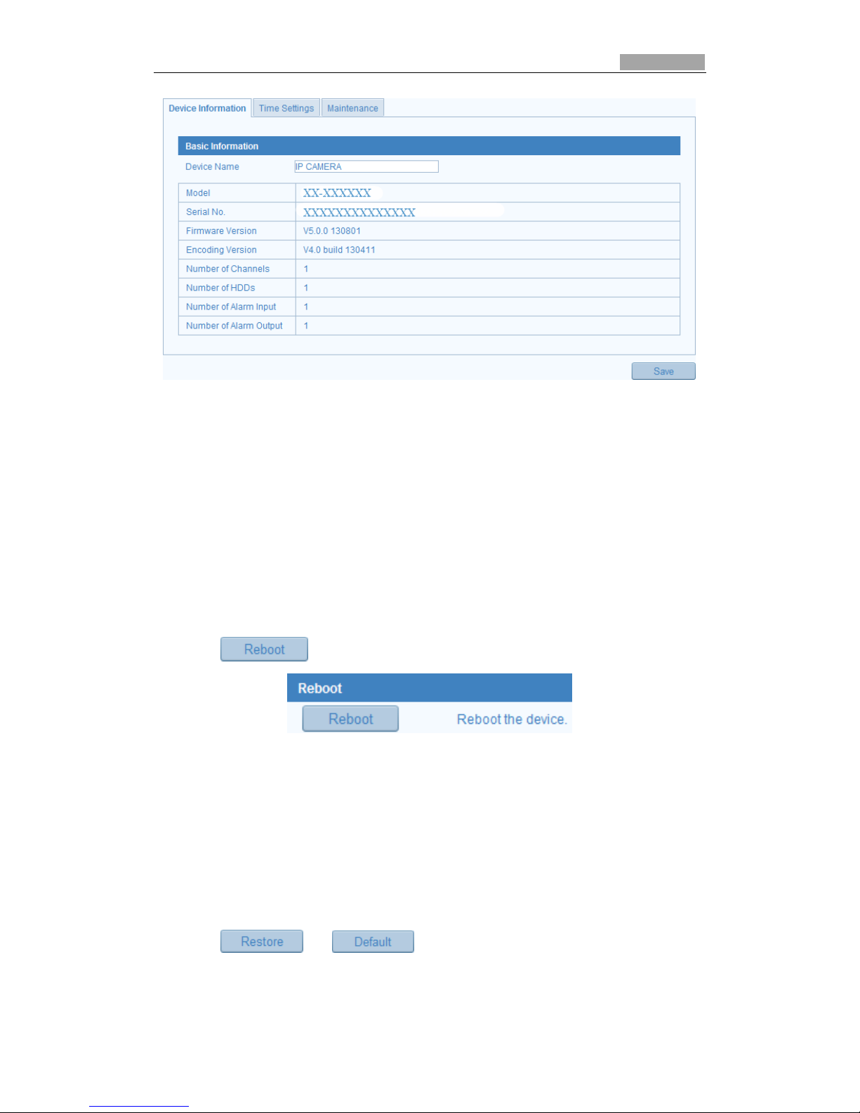
9.5 Viewing Device Information
Enter the Device Information screen:
Configuration > Basic Configuration> System > Device Information
Or Configuration > Advanced Configuration> System > Device Information
In the Device Information interface, you can edit the Device Name.
Other information from the IP network camera, such as Model, Serial No., Firmware
Version, Encoding Version, Number of Channels, Number of HDDs, Number of Alarm
Input and Number of Alarm Output are displayed. This information cannot be
changed.
Page 69
SmartWatch® IP Network Camera User Manual
69 69
Figure 9-10 Device Information
9.6 Maintenance
9.6.1 Rebooting the Camera
Steps:
1. Enter the Maintenance interface:
Configuration > Basic Configuration> System > Maintenance
Or Configuration > Advanced Configuration> System > Maintenance:
2. Click to reboot the IP network camera.
Figure 9-11 Reboot the Device
9.6.2 Restoring Default Settings
Steps:
1. Enter the Maintenance interface:
Configuration > Basic Configuration> System > Maintenance
Or Configuration > Advanced Configuration> System > Maintenance
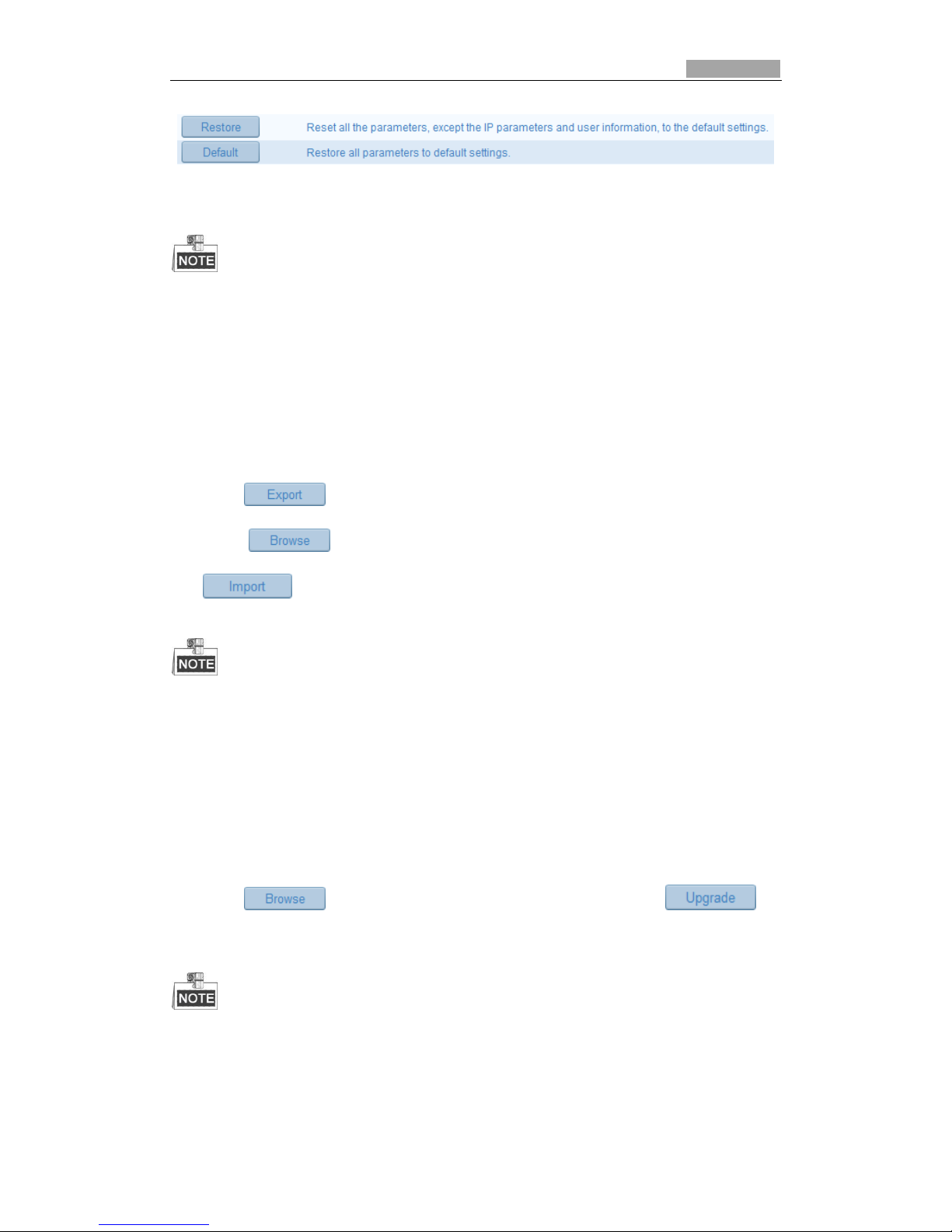
2. Click or to restore the default settings.
Page 70
SmartWatch® IP Network Camera User Manual
70 70
Figure 9-12 Restore Default Settings
After restoring the default settings, the IP address will also be defaulted.
9.6.3 Exporting/ Importing Configuration File
Steps:
Enter the Maintenance interface:
Configuration > Basic Configuration> System > Maintenance
Or Configuration > Advanced Configuration> System > Maintenance
1. Click to save the configuration file of the current device.
2. Click to select the saved configuration file and then click
to start importing configuration file.
You need to reboot the camera after importing a configuration file.
9.6.4 Upgrading the System
Steps:
1. Enter the Maintenance interface:
Configuration > Basic Configuration> System > Maintenance
Or Configuration > Advanced Configuration> System > Maintenance
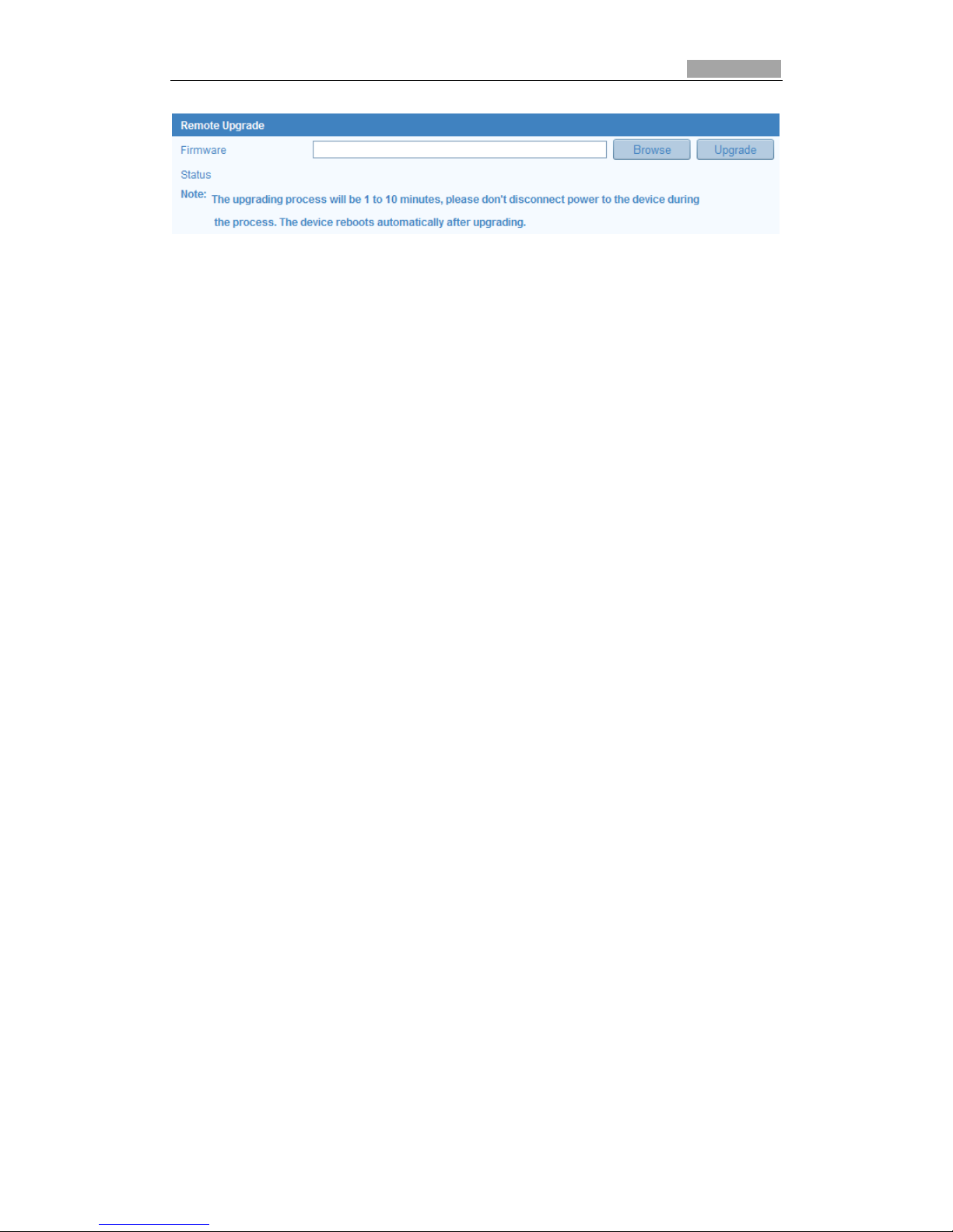
2. Click to select the local upgrade file and then click to
start remote upgrade.
The upgrading process will take 1 to 10 minutes. Please don't disconnect power from the
camera during this process. The camera will reboot automatically after upgrading.
Page 71
SmartWatch® IP Network Camera User Manual
71 71
Figure 9-13 Remote Upgrade
Page 72

SmartWatch® IP Network Camera User Manual
72 72
 Loading...