

Page 1

INSTALLATION/OPERATING MANUAL
CAUTION:
This manual is written for multi DVR systems. The functions, specifications and connections can
be different.
Do not place heavy objects on top of the product.
Do not drop any hard objects or allow liquid to penetrate into the unit.
Regularly brush off dust on the circuit board, connectors, fans and DVR case. Turn of f the power and
unplug the product before cleaning.
Do not attempt to disassemble or repair the unit or replace parts yourself.
Operating Environment:
Keep and use the pr o duct at t em per atures between 0 °C ~4 0 ° C. Ke ep i t awa y from di rec t s unli ght
or heat sources.
Do not install the unit in a humid environment.
Do not expose the product to a smoky or dusty area.
Avoid serious collision. Do not drop the device.
Install the product on a stable and level surface to prevent the device from falling.
Ensure the location planned for DVR installation is well ventilated. Do not block any openings.
Use the product only within the range of rated input/output.
Page 1
Page 2

Table of Contents
Chapter 1 Introduction ................................................................................................................................ 4
1.1 Product Overview.................................................................................................................................. 4
1.2 Main Features ....................................................................................................................................... 4
Chapter 2 Unpacking Inspection and Cable Connections .......................................................................... 7
2.1 Unpacking ............................................................................................................................................. 7
2.2 Rack mount ........................................................................................................................................... 7
2.3 Front Panel............................................................................................................................................ 8
2.4 Connection Diagram ............................................................................................................................. 9
2.5 Audio/V ideo IO Connections ................................................................................................................. 9
2.5.1 Connect Video Input .......................................................................................................................... 9
2.5.2 Selection and Connection of Video Output Devices...................................................................... 100
2.5.3 Audio Signal Input ............................................................................................................................ 10
2.5.4 Audio Output: ................................................................................................................................. 100
Chapter 3 Basic Operation ..................................................................................................................... 122
3.1 Turn Power On .................................................................................................................................. 122
3.2 Turn Power Off .................................................................................................................................. 122
3.3 Log in ................................................................................................................................................ 133
3.4 Preview ............................................................................................................................................. 133
3.5 Desktop Quick Launch ...................................................................................................................... 144
3.5.1 Main Menu ..................................................................................................................................... 144
3.5.2 Video Playback .............................................................................................................................. 155
3.5.3 Recording Control ............................................................................................................................ 19
3.5.4 PTZ Control ...................................................................................................................................... 19
3.5.5 Image Color ................................................................................................................................... 255
3.5.6 Output Adjustment ......................................................................................................................... 256
3.5.7 System Shutdown .......................................................................................................................... 266
3.5.8 Page Switc h ................................................................................................................................... 277
Chapter 4 Main Menu ............................................................................................................................. 288
4.1 Main Menu Navigation ...................................................................................................................... 288
4.2 Video Recording Functions ................................................................................................................. 29
4.2.1 Recording settings ........................................................................................................................... 29
4.2.2 Video Pla yback .............................................................................................................................. 311
4.2.3 Video Backup ................................................................................................................................. 311
4.3 Alarm ................................................................................................................................................. 322
4.3.1 Motion Detection ............................................................................................................................ 322
4.3.2 Video Blind ..................................................................................................................................... 344
4.3.3 Video Loss ..................................................................................................................................... 355
4.3.4 Abnormality .................................................................................................................................... 355
Page 2
Page 3

4.4 System Settings .................................................................................................................................. 36
4.4.1 General Settings .............................................................................................................................. 36
4.4.2 Encoding Settings ............................................................................................................................ 37
4.4.3 Network Settings .............................................................................................................................. 39
4.4.4 Network Service ............................................................................................................................... 39
4.4.5 Output Mode .................................................................................................................................... 48
4.4.6 PTZ Settings .................................................................................................................................... 48
4.4.7 Serial Port Settings .......................................................................................................................... 49
4.4.8 Auto Sequence Settings ................................................................................................................ 500
4.5 M anagement Tools............................................................................................................................ 500
4.5.1Channel Managem ent ...................................................................................................................... 50
4.5.2Hard Drive Management................................................................................................................... 51
4.5.3User Managem ent ............................................................................................................................ 52
4.5.4Online User ....................................................................................................................................... 54
4.5.5Output Adjustment ............................................................................................................................ 55
4.5.6Auto Maintenanc e ............................................................................................................................. 55
4.5.7Restore Default ................................................................................................................................. 55
4.5.8System Upgrade ............................................................................................................................... 56
4.5.9Device Inform ati on ............................................................................................................................ 56
4.5.10 Import/Export ................................................................................................................................. 57
4.6 System Information ............................................................................................................................. 57
4.6.1 Hard Drive Information ..................................................................................................................... 57
4.6.2 BPS .................................................................................................................................................. 58
4.6.3 Log ................................................................................................................................................... 58
4.6.4 Version Information .......................................................................................................................... 59
4.7 System Shutdown ............................................................................................................................. 600
Chapter 5 Cloud Technology Basic Operation........................................................................................ 661
5.1 Cloud technology monitor ................................................................................................................. 661
Chapter 6 FAQ and Maintenance ........................................................................................................... 666
6.1 FAQ ..................................................................................................................................................... 66
6.2 Maintenance ..................................................................................................................................... 732
Appendix 1. Mouse Operations ................................................................................................................ 73
Appendix 2. Hard Driv e Capacity Calculation........................................................................................... 74
Page 3
Page 4

Chapter 1 Introduction
1.1 Product Overview
This device is an excell ent digital surv eillanc e product s peciall y design ed for secur ity
monitoring. The system is more stable with embedded LINUX OS, using standard H.264MP
video compression and unique spatial-temporal reasoning to achieve synchronized high
definition and low bit rate audio/video monitoring. With TCP/IP network tec hnologies, it has
ideally suited to remote data transmission and operation cont r ol vi a w eb ap plicati ons .
This produc t can oper at e not only as a stand alon e l ocal unit, thr ou gh a profess i on al
network video surveillance platfo rm, it can also be connected to other units to form a more
powerful surveillance network system, makin g full use of its capac ity in netw ork i n g an d
remot e m onitorin g.
It is a perfect choice for security applications in industries and sectors such as banking,
telec om m u nication, el ectrici t y, law enforcement, transpor t ation, intel li g ent communi t y,
manufacturing facilities, warehouses, natural resources and water conservation facilities.
1.2 Main Features
Real-time surveillance
·Analog output interface and VGA connector to connect monitoring device or screen display.
·2 BNC outputs and 1 HD VGA for simultaneous real-time monitoring
·Real-time screen preview with zoom-in feature. You may select any area in the display to enlarge
Data storage
·Hibernate inactive hard drive in hard drive management, helping ventilation and reducing power
consumption to extend the useful life of the hard drives
·Data storage using tamper-proof proprietary file format to ensure data security
Compression method
·Live data compression of A/V signals from each channel by independe nt hardware to maintai n the
stable synchronization of sound and image
Page 4
Page 5

Backup feature
·Backup through SATA interfac e and US B inter fac e(to de vices s uch as fl ash dri ve or rem ovable har d
disk)
·Live disk burning, backup burning
·Local archiving by downloading files on hard drives via network to client’s PC
Video playback
·Each channel r ecords all-li ve video independ entl y while sim ultaneously pro viding retri eval, pl ayback,
network monitoring, recording search and downloading
·Various playback modes, simultaneous multi-channel playback, and combination of any desired
channels.
·Select any area of the screen to zoom-in
Network operation
·Real-time remote monitoring through network connection (including mobile phone)
·Remote PTZ control
·Remote control video retrieval and live playback
·Configuration of device parameters through user port
·Live recording and playback on client’s PC
Alarm coordination
·Alarm linkage to camera recording, auto sequence, screen display, buzzing, screenshot snapping,
Email notification and FTP uploading
·Multi-channel relay on/off swi tc h for al arm outputs , fac il itati ng coor dinated actions and on-s i te li ghti ng
control
·Protective circuit on both alarm input and output to prevent damage to main units
Communication interfac e
·RS485 serial port for alarm input, PTZ control and keyboard
·RS232 jack. Expandable ke yboard connection can be us ed for m as ter c ontr ol, s ystem m ai ntenance
and upgrading through connected PC serial port, as well as matrix control
·Standard Ethernet interface for remote network access
Smart operation
·Mouse operation
Page 5
Page 6

·Keyboard operation
·Quick copy-paste function to clone same settings in the menu
Other features
·2 X 12V power outputs
·Timer
Page 6
Page 7

Chapter 2 Unpacking Inspection and Cable Connections
2.1 Unpacking
When you receive the product, first inspect the package for visible damage. The
protec tive p acking mat eri als us ed for t he pr oduct c an han dle mos t acci dental s hocks and
impacts during transport.
Then, take out the device, remove protective film from the DVR, and inspect the product
for any vis i bl e sign of damag e.
Final l y, open t h e case t o c h ec k for loos e connec ti ons to fr ont p anel data cables , power
cord, power supply to fans and motherboard.
1.Fro nt and Re ar Pan els
♦ Refer to th e us er m anual f or details on t he f unc tions of vari ous f ront p anel b uttons
and rear panel connectors.
♦ Please verify carefully the product model on the front panel plaque and make sure it
is the m od el you ordered.
Do not tear off the label on the rear p anel as it is extremely important to our post-sale
service. Wh en y o u c o ntact our post-sa le s erv ic e, y o u wi ll ne ed t o provide th e mo del
number and serial number printed on the label.
2. Items to be checked after opening the case
In addi tion to chec kin g f or visib le d amag e, pl eas e insp ect f or an y loo se conn ec tions to
the front panel cable s, power cord and motherboard.
2.2 Rac k mou n t
The product uses a standard 1U chassis and can be mounted to a standard rack.
Installation procedures and precautions:
1、Make sure the room temperature is below 35° C (95°F);
2、Allow 15cm (6”) clearance around the product for proper ventilation;
3、Always fill the rack from bottom up;
4、Consideration should be giv en to protecting the rack from circuit ov erload when mounting multiple
units to the rack.
Page 7
Page 8

No.
Name
Symbol
Function
1
PWR
Boot up or shut down
2
Manually begins recording
3
4
Back to previous Menu or cancel
operation in the function menu
Back to preview status when in the
playback status
5
Menu
MENU
Enter into Mainmenu
6
Enter,
Enter into Mainmenu
7
Press up or dow n to select record file in
the playback status
In t h e Pr e view screen,press up or down
to go into 1/4/8/9/16 multiple channels
screen
2.3 Front Pane l
(1)Power (2)Rec (3)IR (4)ESC (5)Menu (6)Enter (7)Arrow
Functions of front p anel buttons
Power
Recording REC
IR IR
ESC ESC
Enter ENTER
<
>
Arrow
Remote controlling indicator light
In the Menu,press up or down to move
Cursor
Change configuration in the Drop-down
menu
Page 8
Page 9
In the Menu,press left or right to move
Cursor
In the playback status,press left or right
to move cursor of function button
Back to preview status when in the
playback status
< >
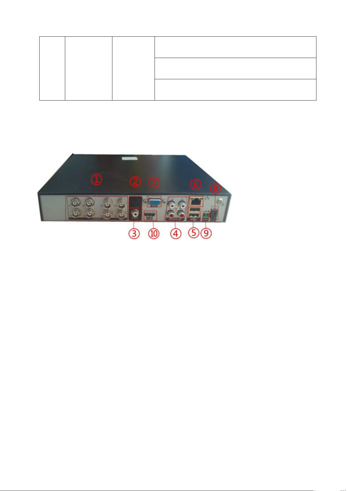
2.4 Connection Diagram
(1)Video input (2)Video output (3)Audio output (4)Audio input
(5)USB interface (6)Network interface (7) VGA interface
(8)Power input (9) RS485 PTZ output (10) HDMI output
2.5 Audio/Video IO Connections
2.5.1 Connec t Video Input
The DVR has BNC video input connectors. Signal requirements:PAL/NTSC BNC(1.0V,75Ω)。
Video signal should conform to the national standards with a higher signal-to-noise ratio, low
distort ion and low i nterference; r equiring pic ture to be cl ear, with no image distorti on, with natural color
and appropriate brightness.
Ensure stable and reliable camera signal:
Install the cam era i n appropriate l ocations to avoid bac klighti ng and surroundi ngs with dim light or
use low illumination camera and camera with ef fective backlight compensation.
Cameras should share reliable common ground with the DVR to ensure the normal operation of the
camera.
Page 9
Page 10

Ensure stable and reliable line transmission of signal:
Use high-qual ity, shielded vi deo coa xial cabl e. Selec t the ri ght t ype dependi ng on the trans mi tting
distance. I f the distance is extensive, you should consider the use of cable with twisted pairs, v ideo signal
enhancing devices and fiber-optic cables to maintain the signal quality.
Keep the video transmitting line away from other devices and circuits that generate strong
electromagnetic interference. In particular, protect it against high voltage power surge.
Ensure secure wire connections:
Signal li nes and shi elded cabl es shoul d ha ve tight connecti ons. Avoid fal se sol dering and pre vent
oxidation of the solder connection surface.
2.5.2 Selection and Connection of Video Output Devices
PAL/NTSC BNC (1.0V
, 75Ω) video output and VGA output exist ( They can operate
P-P
simultaneously)
When using a computer monitor as an alternative surveillance display, pay attention to the following:
1. In order t o pr ol ong the li fe of the equi pm ent, do n ot l ea ve the m onitor powe r-on for an extended
period of time;
2. Perform demagnetizing regularly to ensure proper working status of the monitor;
3. Keep it away from devices generating strong electromagnetic interference.
TV is not a r eli abl e alter native as the video ou tput de vice. It al s o req ui res m i nimizing the power -on
time and ti ght c ontrol of interference from surroundi ng power source and devices. Possible electricity
leakage from low quality TV could result in damage to other devices.
2.5.3 Audio Signal Input
AV interface for audio input.
With higher impedance, active pickup is required.
As with video input, th e audio transm ission li ne should minimize inter ference, prevent inad equate
soldering and faulty connections. Pay special attention to protection against a high voltage power surge.
2.5.4 Audio Output:
The par ameter of the DVR audio output s ignal i s usually greater tha n 200m v 1kΩ ( AV). It can be
Page 10
Page 11

directly connected to low impedance headphones, powered speakers or drive other audio output devices
through an ampl if ier. If spatial isolation cannot be established between external speakers and pickups, it
could result in a whistling sound. In the event, you may:
1、 Use pickups with better directivity;
2、 Adjust speaker volume to the level below whistle threshold;
3、 Use sound-absorbing materials in the working environment to reduce sound reflection and
improve room acoustics;
4、 Adjust the layouts of pickups and speakers to reduce the occurrence of whistling.
Connections to PTZ
A. The PTZ decoder must share a common ground with the DVR or possible presence of
common-mode voltage may cause you to lose control of the PTZ.
We recommend shielded twisted pair cable with its overall shield being used for common
ground;
B. Prevent against high-voltage power surge. Wire cables must be able to protect equipment from
lightning
C. Connect a 1 20 Ohm res istor in par allel at the far-end to reduce reflec tion and guarant ee the
signal quality;
D. T he AB-wire connecti ons of the DVR’s 485 cable cannot be combined wi th 485 c ables from
other output devices;
E. AB line voltage of the decoder should be lower than 5V.
Ground Wires of front-end equipment
Incorrect grounding may result in chips being burned.
Page 11
Page 12

Chapter 3 Basic Operation
Note:Grayed out button means the function is not supported
3.1 Turn Power On
Conn ect th e u nit to a suit able power out let befor e t urning on the p ower s witch on the
rear panel. Power indicator light is on and DVR starts booting. When the booting is
finished, a “beep” is heard. Multi-scr een is the default video output mode. If the unit is
turned on within the scheduled recording time period, the system will start scheduled
rec or ding automatic ally. Rec ording indic ator on the c orresp onding channel turns on. The
system w or ks normall y.
Note: 1. Before turning on the power, make sure the mains voltage matches sliding switch of the unit and
the power cord is connected correctly.
2. External power supply requires 220V±10% /50Hz.
W e recom mend the us e of power supply with s table volt age and less ripple interf erenc e.
Whenever possible, consider the use of UPS for power backup.
3.2 Turn Power Off
The unit can be turned off using softswitch and “hardswitch”. Softswitch, Sele ct 【Turn
Off】in【Main Menu】>【Shutdown System】; Hardswitch,Press the power switch on the
rear panel to turn off the power.
Instructions:
1. Power failure recovery
If the DVR is shut down unexpectedly during recording, after the unit is rebooted it
will automatically save the data before the shutdown and return to where it was.
2. Replacing hard drives
You must turn off the rear panel power switch be fore replacing the hard drive.
3. Replacing batteries
Save the configuration information and turn off the rear panel power switch before
Page 12
Page 13
replacing batteries. The DVR uses button batteries. You need to check the system time
peri odically. Batter i es need be replac ed w h en t h e tim e b ec omes inac c urate, we
recommend replacing batteries of the same type once every year.
Note: Save the configuration before replacing batteries on the motherboard or
the config urati on information wil l be lost .
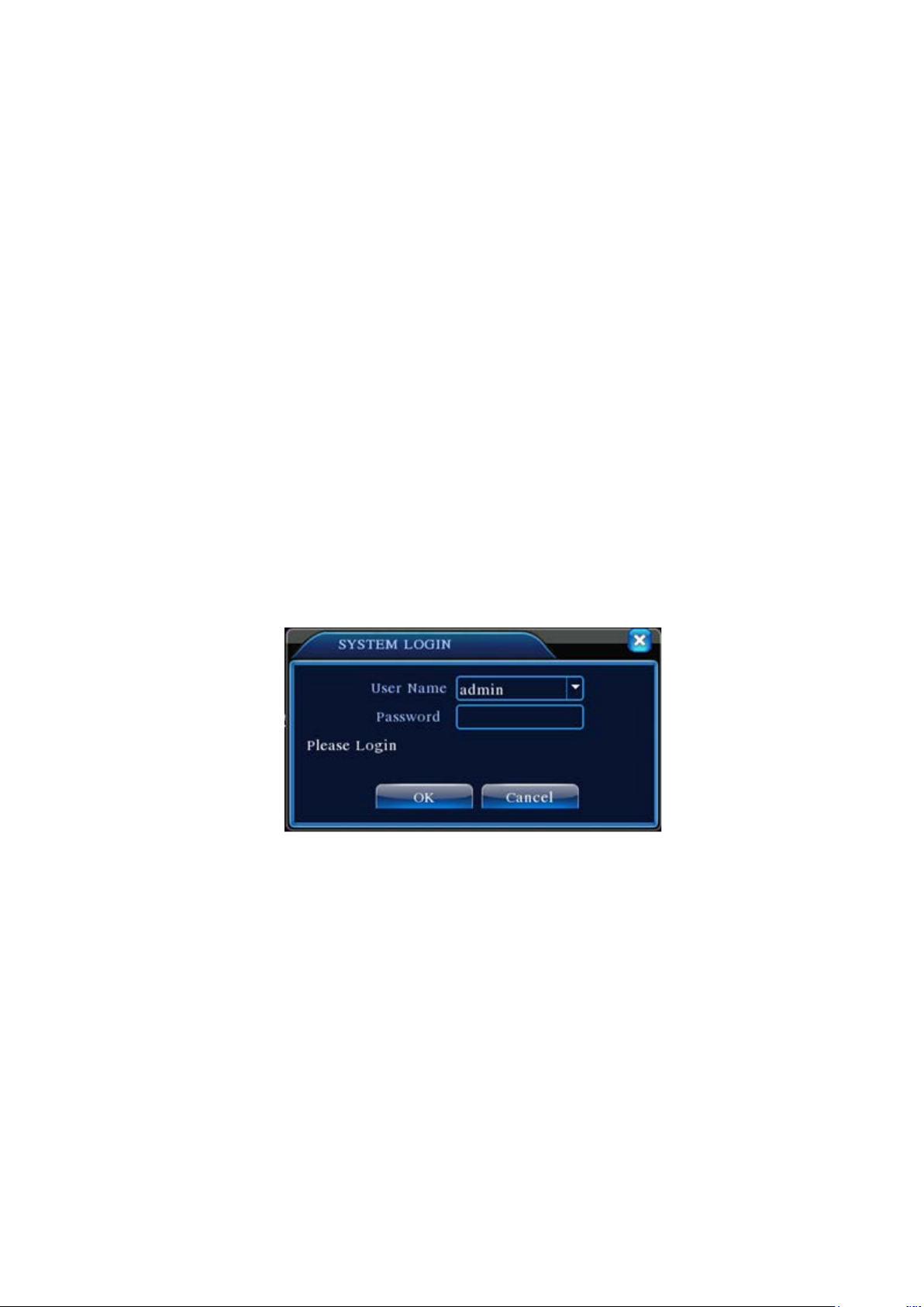
3.3 Log i n
After normal start-up, the operator is asked to log in. The system will provide
corresponding functions based on user permissions.
Factory default setting provides 3 user types with no password: admin, guest, and
default. The factory s etting of admin user has superuser per missions while the def aults
for guest and default are limited to preview and playback. Admin and guest user s may
change their password but cannot change the permissions. Default user is a default
login us er. Def au lt user may ch ang e permissi ons but not the password.
Figure 3.1 Log In
Password prot ectio n: If the password is en tered incorrect ly on 3 co nsecu tiv e o ccasion s, the
system will display a warning ala rm; After 5 con secutive attempts, the account w ill be locked
(The account will be unlocked automatically upon system reboot or after 30 minutes).
For security rea son s, plea se change your U ser ID and Password u nd er “ User M anag emen t”
(refer to Chapter 4.5.2 User Management) after initial login.
3.4 Preview
After n orm al logi n, t he uni t sh ows th e pr eview s cr een . Right clic k th e mous e to s witc h
displays.
Page 13
Page 14
1
3
2
4
Each preview screen ca n show date, time, channel name, m onitori ng c hannel playback
and alarm status.
Recording
Motion detected
3.5 De sktop Quic k La unch
Table 3.1 Preview Symbols
Video loss
Camera lock
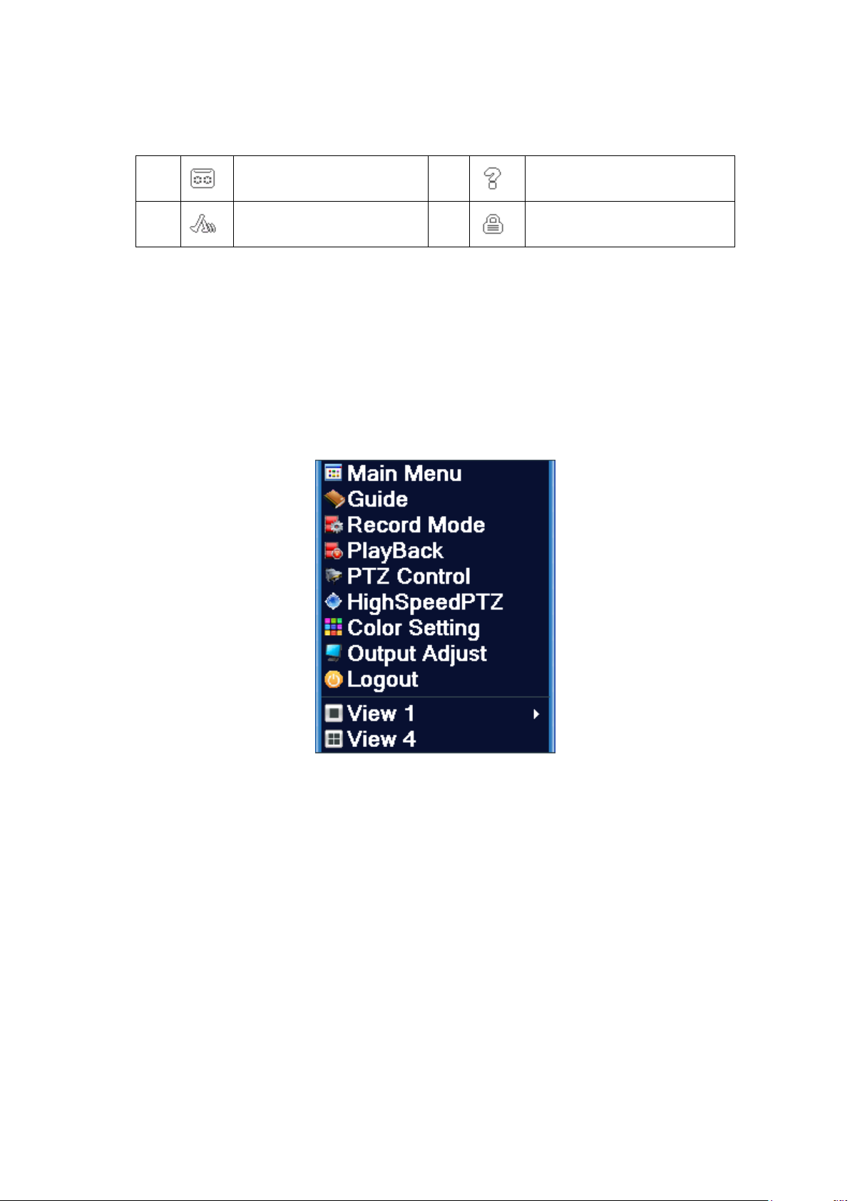
In Preview mode, right click the mouse to pop-up Quick Launch menu as shown in
Figure 3.2. Qui ck L aunch men u i nclu des: M ain M enu, G uid e, R ecord e Mode, PlayBack,
PTZ Contr ol, High sp ee d PTZ, Color Setting, Output adju st,and Log out.
Figure 3.2 Quick Launch Menu
3.5.1 Main Menu
The main menu includes operating functions of the device.
Page 14
Page 15
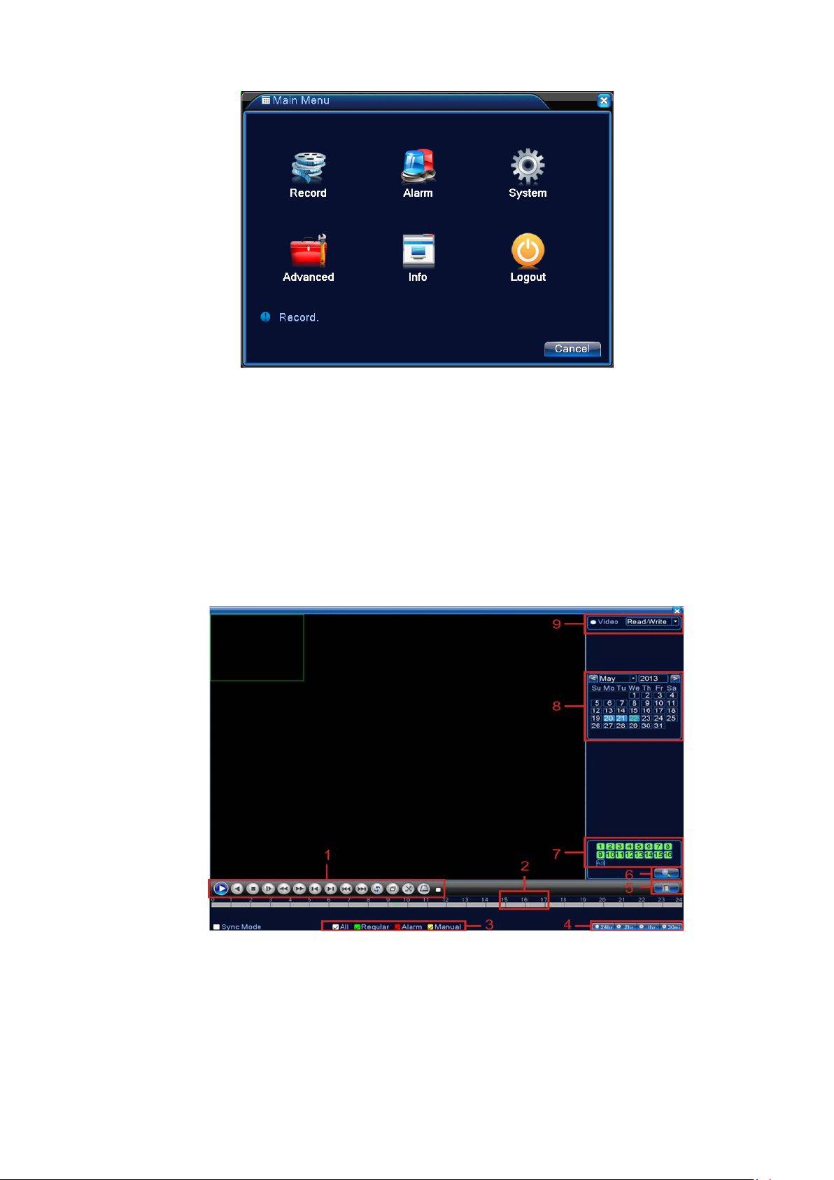
Figure 3.3 Main Menu
3.5.2 Video Playback
Playback video files on the hard drives. Playback page is accessible by either using desktop quick
launch or entering 【Main Menu】>【Recording Functions】>【Video Playback】.
Note: For normal playback, the hard dri ve containi ng the file mus t be set up as read/wri te or read-only
(refer to 4.5.1 Hard Drive Management).
Page 15
Page 16
Prompt
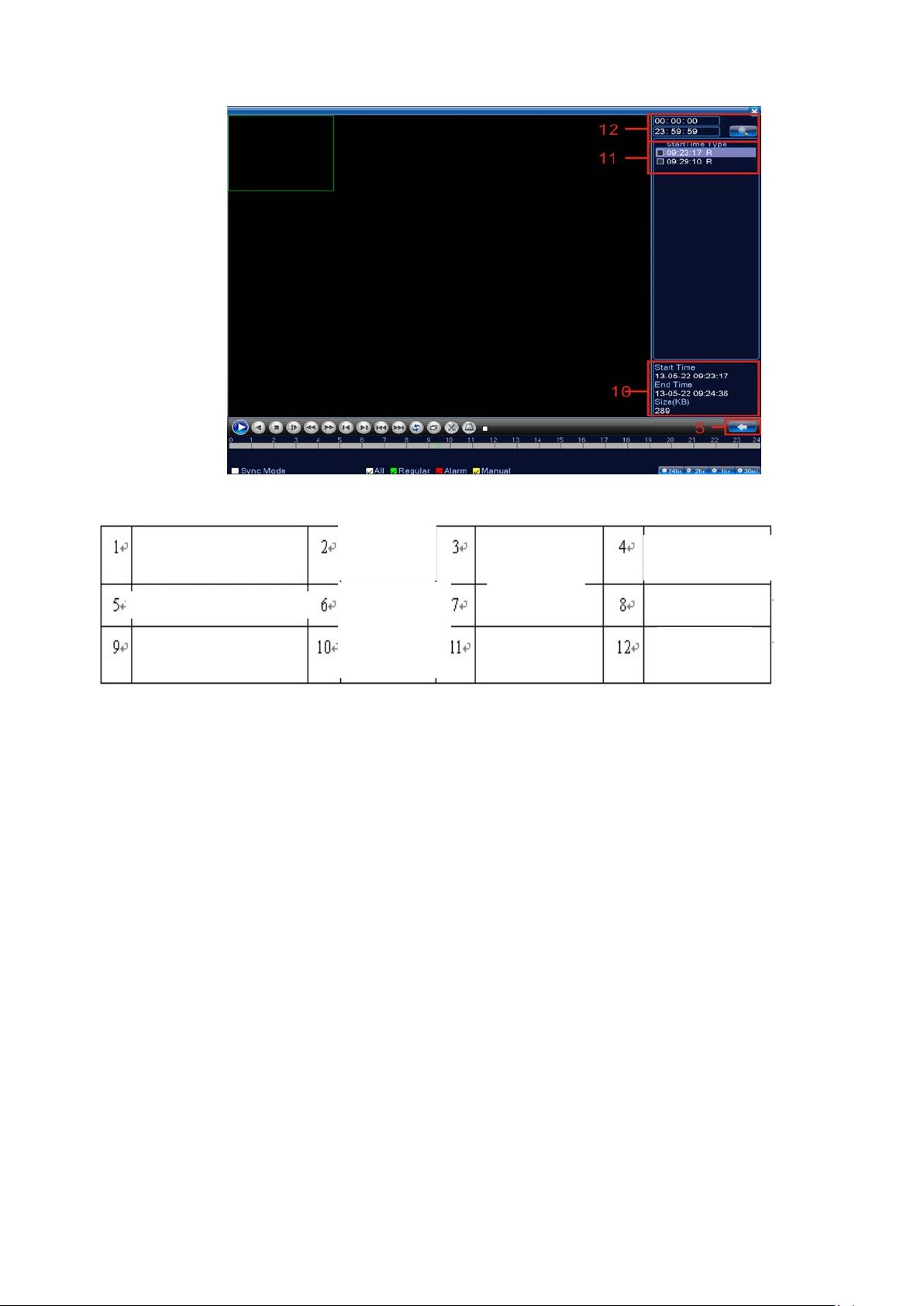
Figure 3.4 Video Playbac k
Playback Control
Storage Device Selection
Operating
File Search
File Information
Recording Type
Channel Selection
File List
Progress Bar Option
Date Selection
Time Inqui ry
Descriptions of Table【Playback Control】please see below:
【File Lis t】displays all files match the search criteria;
【File Information】Show details of selected files;
【File Backup】Bac kup f iles tic ked. Clic k t he b utt on t o sh ow t he s creen as Fi gure 3. 5
and follow the instructions.
Note: Install a storage device large enough for the backup files before the operation;
If the bac kup is ter minated, fil es alread y copied to the stor age device can be pl ayed back
independently.
Page 16
Page 17
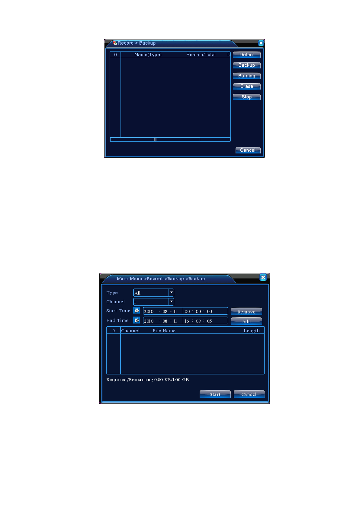
:
Figure 3.5 Storage Device Check
Detect: Detect storage devices connected to the unit. It could be USB flash drives or hard
drives.
Erase: Select the devices you wish to clean up. Click Erase to delete files on the devices.
Stop: Stop the backup;
Backup: Click Backup to show the di alog as Figur e 3.6. Backup can be setup based on fil e
type, channel, or time.
Burning
*******************************************************
Figure 3.6 Record Backup
Empty: Empty file information shown;
Add: Show all information matching the specified file properties;
Start/Stop: After selecting the files, click Start to backup and Stop to terminate the backup.
Page 17
Page 18
Note: During backup, you may exit the page to execute other functions.
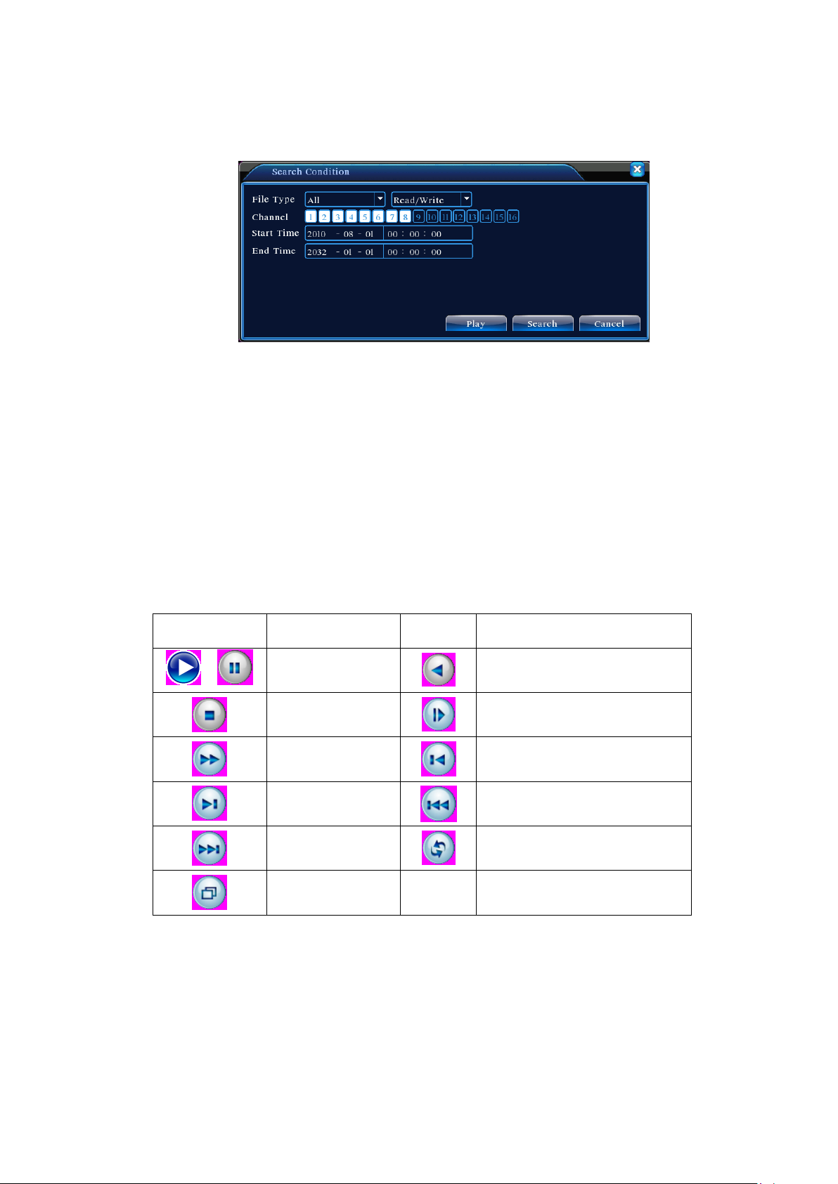
【File S ear c h】Search for records ba sed on the specified search criteria;
Figur e 3. 7 Fil e Search
File Type: Select the type of files to be played back;
Hard Drive Selection: Select the type of storage device;
Channel: Choose the channel number fo r playback. “All” means all channels;
Start time: Specify the start time of the record being searched.
End time: Sp ec ify the end ti m e of the record being searched.
Descriptions of Table【Playback Control】please see below:
Keys Functions Keys Functions
Play reverse
Step forward
Play last frame
Play last file
Loop
/
Play/Pause
Stop
Fast forward
Play next frame
Play next file
Full Screen
Table 3.2 Playback Control Keys
Note: Frame playback can only be used in Pause mode.
【Operation tips】Show the function of the button indicated by the cursor.
Special Fe at ures:
Accurate Playback:In 【Search Criteria】 window, enter the time (hour, minute, second)
Page 18
Page 19

of the record being searched. Click Enter to acc ess playback screen. Click Playback
button directly to perform Accurate Playba ck of the record searched;
Zoom In: W hen perform ing singl e-screen full s creen playback, l eft clic k the mouse to sel ect any
area on the scr een. Left click the mous e again within the selec ted area to playback in zoom-i n mode.
Right click the mouse to exit zoom-in.
3.5.3 Recording Control
Control rec ording on each channel . Highlight ed “●” indicates the current recordi ng status of the
channel. Playback page is accessible by either using desktop quick launch or entering 【Rig ht Click】>
【Recor mode】.
Figure 3.8 Recording Control
【Schedule】Record in accordance with the configuration parameters;
【Manual】Regardless of the current status of the channel, selecting “Manual” will start the recording
on the corresponding channel;
【STOP】Regardless of the current status of the channel, selecting “STOP” will stop the recording on
the corresponding channel;
3.5.4 PTZ Control
Control Pan/Tilt/Zoom connected to the device. Use desktop quick launch to enter the menu.
Control interface is shown as in Figure 3.10. Functions supported: Control PTZ directions, step
length, zoom, focus, aperture, operating preset, point-to-point patrol, trace, boundary line scanning,
auxiliary switch, light switch, and horizontal rotation.
Note 1. Before operating, m ak e sur e the A/B cabl es of the dom e are proper l y conne c ted to the DVR
Page 19
Page 20
A/B jacks;
2. Setup PTZ parameters in 【Right Click】>【PTZ Setup】;
3. Functions supported by PTZ depend on the features supported by PTZ protocol.
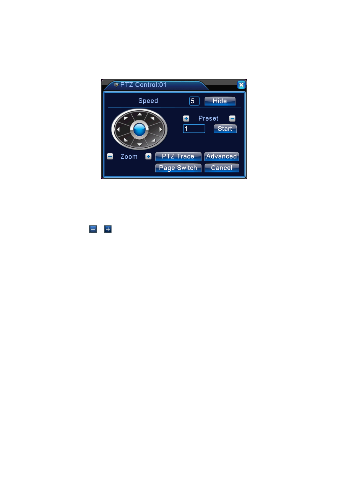
Figure 3.9 PTZ Control
【Step length】Determ i ne the rotati ng range of th e PTZ. The l arger the sett ing, the l onger th e step
length. Setting range:1 ~ 8 ;
【Zoom】Use
【Direc tion Control】Control the rotation of the PT Z. Support controls in 8 directions(fr ont panel
supports only 4 directions);
【High Speed PTZ 】After selecti on, the selected chann el displ ays full -screen. Hold down the left
button of the mouse to quickly rotate and position the PTZ. Turning the mouse wheel while holding down
the left button can adjust the camera zoom;
【Set】Access function setting menu;
【Page Switch】Enter function control menu.
/ keys to adjust camera magnification;
Special Fe at ures:
1. Preset
Select certain direction as preset. PTZ automatically rotates in the direction based on the preset
value.
1)Preset setup
To setup a direction as preset, follow these steps:
Step 1: In Figure 3.10, use arr ow keys to rotate the PTZ to the desired pres et position. Cl ick
Page 20
Page 21
input box
Position
Preset input
box
Setting key to enter Figure 3.11;
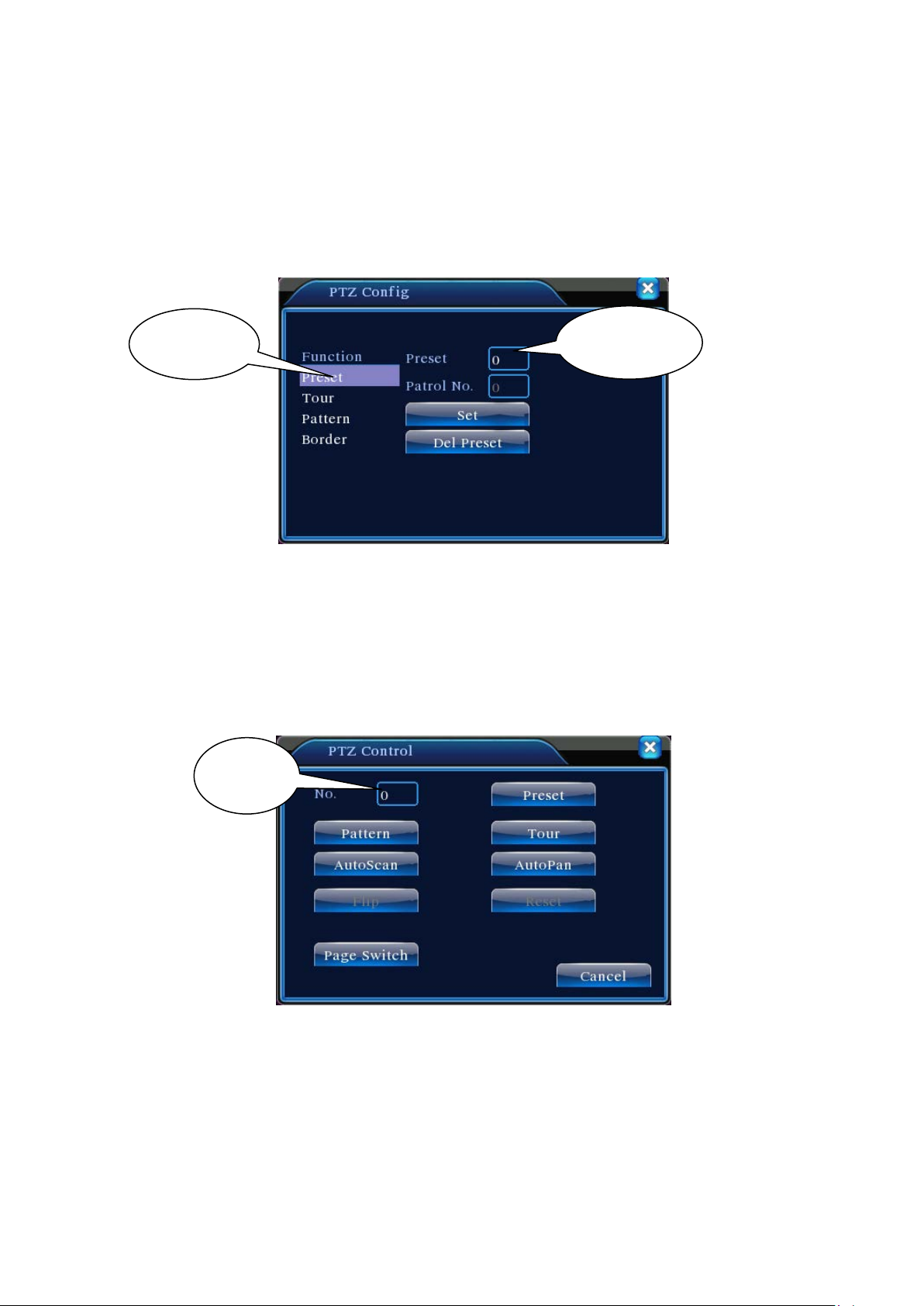
Step 2: Click Preset button and input preset value in Preset Position box;
Step 3: Click Set to return to Figure 3.10. When complete, each preset value has a
corresponding preset position.
Del Preset: Enter the preset value, click Del Preset button to clear the preset setting.
Preset
Figure 3.10 Preset position setup
2)Prese t posi tion call-up
In Figure 3.10, click Page Switch button to enter PTZ control interface as shown in Figure 3.12.
Enter the n um ber of the preset i n Value Input Box. Click Pr eset Position to r otate the PTZ to the
corresponding preset position.
Value
repeatedly following the Point-to-Point patrol setup.
Figure 3.11 PTZ Control
2. Point-to-Point Patrol
Connect mul tiple pres et positions to c onstruct a patrol route. PTZ will s weep the patrol route
1)Point-to-Point Patrol Setup
Page 21
Page 22
Patrol route is the trace line consisted of multiple preset positions. To set up:
Step 1: In Figure 3. 10, use arrow ke ys to rotat e the PT Z to the des ired pr eset dir ection. Cl ick
Set key to enter Figure 3.13;
Step 2: Click the Point-to-Point Patrol key and enter a route number in Patrol Route box.
Click Ad d Preset Posit ion key to i nput preset num ber in the dialog bo x. That wi ll be one of the
preset points selected for patrol;
(You may add or delete preset points after finishing the patrol route setup)
Step 3: Repeat Steps 1 and 2 until the desired patrol route includes all preset points.
Del Preset: Enter the preset value, click Del Preset button to clear the setting for preset points.
Clear Patrol Ro ut e: Enter the patr ol r oute num ber, clic k Clear Patrol Rou te button to clear al l
point settings along the patrol route.
Figure 3.12 Point-to-Point Patrol Setup
2) Point-to-Point Patrol Call-up
In Figure 3.10, click Page Switch button to enter PTZ control interface as shown in Figure 3.12.
Enter Point-to-Point Patrol number in Value Input box. Click Point-to-Point Patrol key to start PTZ
patrol repeatedly. Click Stop key to terminate the patrol.
3. Trace
Using PTZ control to setup a patrol trace. Call it up to have PTZ patrolling along the trace
repeatedly.
1) Setup Trace
To set up the trace, follow the steps below:
Step 1: In Figure 3.10, click Set key to open Figure 3.14;
Step 2: Click Trace key to enter trace number in the value input box;
Page 22
Page 23

Trace
Step 3: Click Start button to enter the page shown in Figure 3.10 and adjust Zoom, Focus,
Aperture, and Direction, etc. Click Set and return to Figure 3.14;
Step 4: Clic k End to complet e the setup. T race num ber now has i ts corres ponding r oute. Ri ght
click to exit Setting page.
Trace value i nput box
Figure 3.13 Trace Setup
2) Trace call-up
In Figure 3.10, click Page Switch button to enter PTZ control interface as shown in Figure 3.12.
Click Trace button and enter trac e num ber i n Value Input box. PTZ will operate foll owi ng the route
setup. Click arrow keys to stop.
4. Boundary Line Scanning
Set up a horizontal route and call up line scan to have PTZ run repeatedly on given route.
1) Line Scan Setup
Follow below steps to set up a section of horizontal curve as the trace for PTZ search:
Step 1: In Figure 3. 10, use arrow ke ys to rotat e the PT Z to the des ired pr eset direc tion. Cl ick
Set key to enter Figure 3.15. Select the left boundary and return to Figure 3.10;
Step 2: Use arrow keys to selec t the des i red pos iti on. Cli ck Set to enter Figure 3.15 and sel ect
the right boundary. Then return to Figure 3.10;
Step 3: Complete the setting for left and right boundaries of the position.
Note: When left and right boundaries are on the same horizontal level, PTZ will rotate counter
clockwise from left boundary to the right;
If they are not on the same level, PTZ uses the end of the horizontal trace connecting to the left
boundary as the right boundary point and rotate anticlockwise from the left to the right.
Page 23
Page 24

Settings
Left/Right Boundary
Boundary Line Scan
?
Figure 3.14 Set up line scan boundary
2) Line Scan Call Up
In Figure 3.10, c l ic k Page Swit ch button to op en th e PT Z c ontr ol i nterf ace as show n in F igur e
3.12. Clic k Line Scan button. PTZ wi ll rotate repeatedly following the route set up. Cli c k Stop key
to terminate the line scan.
5. Horizontal Rotation
Clic k Hori zontal Rotati on button to hor izontal ly rotate the PT Z ( rel ative to the c am era' s ori ginal
position). Click Stop key to terminate the rotation.
6. Reverse Rotation
Click Horizontal Rotation button to reverse the rotation of the PTZ.
7. Reset
PTZ restarts. Values of all settings return to zero.
8. Page Switch
In Figure 3.12, click Page Switch to enter Figure 3.16 for auxiliary feature setup. Each auxiliary
number corresponds to an AUX switch on the decoder.
?
Page 24
Page 25

Figure 3.15 Auxiliary Feature Control
【Direct-V iew Auxiliary Operation】Select the auxiliary device and On/Off switch to operate;
【Auxiliar y Number Operation】O perate t he corresponding On/Off sw itch in acc ordance with
PTZ protocols;
【Page Switch】I n Figure 3.16, click Page Switch to enter Figure 3.10. Access the PTZ menu
to make changes using the available control keys.
3.5.5 Image Color
Access the interface through the desktop quick launch menu. Set up image parameters of the
selected channel (current channel in single-screen preview, or the channel where the cursor lies in
multi-sc reen preview). Image param eters incl ude: Hue, Brightness, C ontrast, and Saturati on. It is als o
possible to set up different image parameters in two different time periods if needed.
Figure 3.16 Image Color
3.5.6 Output Adjustment
To adjust the parameters of the area for T V output, enter Outp ut Adj ustm ent interface throug h the
desktop quick launch menu or by clicking 【Right Click】>【Output Adjustment】.
Page 25
Page 26
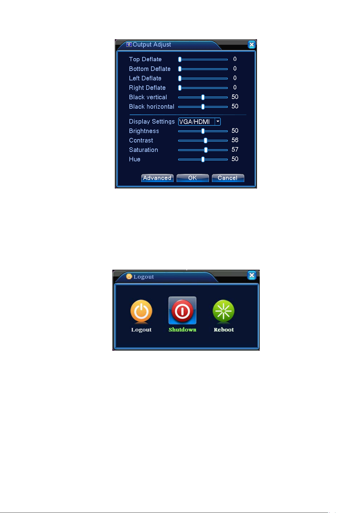
Figure 3.17 TV Tuning
3.5.7 System Shutdown
To Log off, shutdown, or restart the system, open the System Shutdown interface through the
desktop quick launch menu or selecting in 【Main Menu】.
Figure 3.18 Shut down the system
【Log Out】Exit the menu. Need to re-enter the password on the next visit;
【Shut Down】Exit the system and turn off the power;
After press the Shut Down key, a progress bar pops up for shutdown confirmation.
Shutdown will be executed in 3 seconds unless it’s cancelled.
【Reboot】Exit, then restart the system.
Page 26
Page 27

3.5.8 Page Switch
Based on your selection, preview single-screen, 4-screen, 8-screen, 9-screen, and 16-screen.
Page 27
Page 28

Recording
Set up configurati on, t ype, and ti m e peri ods for rec or ding on
Set up motion detection alarm channel, sensitivity, range and
Set up video masking alarm channel, sensitivity, and
Set up video loss alarm channel and parameters for
No HDD, HDD err or, HDD capaci ty not enough, netw ork cut ,
Set system time, for mat of date and time, language, de vice
Set parameters of main code and sub-code streaming for
Network
Set basic network parameters, parameters of DHCP and
Network
PPPOE, NTP, Email, IP access rights, DDNS, mobile phone
Name channels, set up preview prompt status, transparency,
Set up channels, PTZ protocol, address, baud rate, data bits,
RS323
Chapter 4 Main Menu
4.1 Mai n Menu Navigation
Main Menu Submenu Feature Overview
settings
Record
Alarm
Playback Video search, playback, and save
Backup Check and format backup devices. Backup selected files
Motion
Detection
Video
Masking
Video Loss
each channel
parameters for coordinated actions: arm schedule, alarm
output, screen prompts, recording, PTZ, and auto sequence
parameters for coordinated actions: arm schedule, alarm
output, screen prompts, recording, PTZ, and auto sequence
coordinated actions: arm schedule, alarm output, screen
System
Settings
Abnormality
General
Settings
Encoding
Settings
Settings
Service
Output Mode
prompts, recording, PTZ, and auto sequence
IP Conflict, linkage parameters, screen hint or buzz.
response w hen disk is full, l ocal device seri al number, video
format, output mode, standby time, and daylight savings time
each channel: Encoding mode, Resolution, FPS, Stream
control, Image defini ti on t ype, Stream value, I-fram e int er val,
and Video/Audio enabling
DNS, High-speed network download
monitoring, FTP, wireless call in, UPNP, simple DDNS
area coverage, time and channel titles overlay
PTZ Settings
Device
stop bits, parity
Set serial port funcion, baud rate, date bit, stop bit, check.
Page 28
Page 29

Auto
Set channel mode, chec k channel s tatus and configur e the
Hard Drive
Set specified hard drive as read/write disk, read-only disk,
User
Change user and user group. Change password. Add user
Force disconnection of a user logged into the network.
Auto
Info
ort
Reset setti ng s tatus: G eneral settings , enc odi ngs, r ecording,
System
Management
Tools
Sequence
Set auto sequence mode and intervals
Settings
Digital
digital channel, ect.
Management
Management
redundant drive, data deletion, data recovery .
and user group. Delete user and user group
Online User
Disconnect and freeze the account until next reboot.
TV Tuning Adjust upper/lower and left/right side margins of the TV
Set up system auto reboot, auto file deletion
Maintenance
Device
Import/Exp
device hardware configuration and message
Export the device's log or configuration to external
device(like USB flash disk);Input the configuration with
external device(like USB flash disk).
Restore
alarm, network, network services, preview playback, serial
Default
port, and user account management
Upgrade through external device (eg. USB)
Upgrade
HDD
SATA connection state,information for all install Storage
BPS Bitrate Info
Info
LOG Information of System Log
Version Display software version and build date
Logout Logout Logout the OSD menu or reset/restart the system
4.2 V id eo Recordi n g Function s
The DVR can perform functions related to video recording: recording settings , video playback,
video backup.
4.2.1 Recording settings
Set recordi ng parameters on monitori ng channels. At initial startup, the s ys tem defaul ts to 24 hour s
Page 29
Page 30

Schedule
【
continuous recording. Corresponding settings can be defined by entering 【Main Menu】>【V ideo Recording
Functions】>【Recording Conf.】
Note: For normal rec ording, at least one of the hard dri ves shoul d be set up as read/wri te disk (refer to
Chapter 4.5.1 Hard Drive Management for more details).
Figure 4.1 Recording Settings
【Channel】Select proper channel for Channel Setup. Choose ALL if applying the settings to all
channels;
【Redundancy】Selec t redundancy function to h ave dual bac kups of the video fil es, i.e. record the
video to both hard drives simultaneousl y. The DVR needs ha ve two hard drives installed with one s et
as the read/write disk and the other as redundant disk (refer to Chapter 4.5.1 Hard Drive Management
for more details);
【Length】Set the time duration of each video file. Default is 60 minutes;
【Pre-Record】Capture the moments 1-30 seconds before an event(actual tim e could be different
depending on the bit stream);
【Record Mode】Set recording status. There are three statuses: Configured, manual, and off;
period defined;
Manual: Regardless the current status of the channel, select “Manual” will start general
: Record in accordance to the rec ording types (general, test and alarm) and time
recording on all channels;
corresponding channel
【Time Period】Set time period for general recording. Recording will only start in the time range
defined;
Recording T y pe】Set recording types. There are three types:general, test, and alarm.
Stop: Regardless the current status of the channel, select “Stop” will stop the recording on the
;
Regular: Conduct general recording in the defined time period. The type of video file is
marked "R";
Detect: Duri ng speci fi ed time range, tri gger “m oti on detec tion” , “video m asking”, and “ vide o
Page 30
Page 31

loss” alarm signals. The corresponding alarm settings will turn on the recording function
and start test recording. The type of video file is marked “M”;
Note: For “Alarm Function” settings, refer to Alarm Function section in Chapter 4.3.
4.2.2 Video Playback
See Chapter 3.5.2 Video Playback.
4.2.3 Video Backup
Backup DVR video files to an external storage device through this setting.
Note: Install a storage device for file backup before the operation; if the bac kup is terminated, fil es
already copied to the storage device can be played back independently.
If the backup is terminated, files already copied to the storage device can be played back
independently.
Figure 4.2 Storage Device Check
Detect: Detect storage devices connected to the unit. It could be USB flash drives or hard drives.
Erase: Select the devices you wish to clean up. Click Erase to delete files on the devices.
Stop: Stop the backup;
Backup: Click Backup to show the dial og as Fi gure 4.3. Bac kup can be s etup based on fi l e type,
channel, or time.
Burning:****************************
Page 31
Page 32

B
Figure 4.3 Record Backup
ackup format: Configuration the backup file format according to require can choose
Empty: Empty displayed file information;
Add: Show all information matching the specified file properties;
Start/Stop: After selecting the files, click Start to backup and Stop to terminate the backup.
Note: During backup, you may exit the page to execute other functions.
4.3 A larm
Functions of DVR in alarm operation include: motion detection, video masking, video loss,
Abnormality.
4.3.1 Motion Detection
motion detection alarm will be triggered and activate corresponding functions.
Note: Advanced key is the same as the right mouse button.
Through video image analysis, when the system detects motion signals with the preset sensitivity, the
Figure 4.4 Motion Detection
【Channel 】Select the channel to set up motion detection area;
Page 32
Page 33

【Enable】Highlight ■ to enable t he Motion Det ecti on function. C orrespondi ng s ettings c an only b e
defined after Enable is ticked;
【Sensitivity】
【Region】Click Setting to enter the area which is divided into PAL22X18. Colored areas are the areas
covered by motion detection while dark areas are not covered. Set areas as Figure 4.5. Hold down the
left mouse button to toggle the grid blocks. (All areas default to covered)
【Arm/Di sarm Schedul e】
set up as in Figure 4.6. Recording can be scheduled weekly or in a general calendar. Each day is divided
into four ti me sec tions. T he time r ange will take effec t only if th e checkbo x
ticked.
Six settings based on sensitivity level;
Figure 4.5 Set Area
DVR trigger s m otion det ec ti on alar m s ignal onl y dur i ng the tim e per iods
■ befor e the time r ange is
Figure 4.6 Time Range Setup
【Time Interval】Within the scheduled time interval, if there are several occurrences, the detection only
triggers alarm in sequence;
【Alarm Output】When motion occurs, the setting will activate corresponding external devices
connected to the alarm output port;
【Delay】Indicate the extended time for which the alarm will continue after the alarm ends, ranging from
10~300 seconds;
【Recording Channel】Select the desired recording channel (Can be ticked). When alarm is triggered,
the system will activate the recording signal on that channel;
Note: T o perform corresponding video recording, it requires the settings in 【Record Settings】
activate test recording in the defined time periods
Page 33
to
Page 34

【Auto Sequence】Highlighted ■ indicates i t is s elected. When alarm signal is pr esent, the s el ected
channel wi ll start single-screen auto sequence preview. The inter val for aut o sequence is
defined in
【Snapshot】Select the desired recording channel (Can be ticked). W hen alarm is triggered, the
system will activate a snapshot signal on that channel;
Note: T o perform the corresponding snapshooting, it requires the settings in 【Record Settings】
activate test recording in the defined time periods
【PTZ Linkage】When alarm occurs, the PTZ on the defined channel will coordinate the action. Set it as
shown in Figure 4.7;
Note: To coordi nate PTZ , you need to set param eters for pr eset points, poi nt-to-point patrol, and
auto sequence in 【Quick Launch】>【PTZ Control】
【System Settings】>【Auto Sequence Settings】;
Figure 4.7 PTZ Linkage
to
【Video Dela y】After the al arm status ends , the alarm r ecording will continue for an extended ti me,
ranging from 10~300 seconds;
【Screen Prompt】The on-screen alarm information prompt pops up on local display;
【EMAIL Notification】Highlight ■ indicates that email notification will be sent to the user when alarm
occurs.
Note: EMAIL Notification requires appropriate settings in 【Netwo rk Service】.
【Beep】 The device gener at es tw o lon g bu z z er beeps when alarm occ ur s .
4.3.2 Video Blind
When the video im age is affected by external c onditions such as dim li ght and reaches the sensiti vity
setting, it will trigger the video blind alarm and activate coordinating functions.
Note: Advanced key is the same as the right mouse button.
Page 34
Page 35

Figure 4.8 Video Blind
To set: refer to Chapter 4.3.1 Motion Detection.
4.3.3 Video Loss
When DVR is unable to receive a channel video signal, it will activate the video loss alarm and
coordinate functions.
Note: Advanced key is the same as the right mouse button.
Figur e 4. 9 Vid eo Loss
To set: refer to Chapter 4.3.1 Motion Detection.
4.3.4 Abnormality
Analyze and test certain hardware and software in current system. When detecting exceptional events,
the unit makes corresponding responses such as screen prompt, buzzer beep, etc.
Page 35
Page 36

Figure 4.10 Abnormality
【Event Type】 Select the exceptional event in the drop-down list for testing
【Enable】Highlight ■ to enable E xception Handling function. Settings can onl y be activated after
Enable is ticked;
【Screen Prompt】The on-screen alarm information prompt pops up on local display;
【Buzzer】 The device generates two long buzzer beeps when the alarm sounds.
4.4 System Settings
To set various function parameters in DVR: general settings, enco ding sett ings, net wo rk settin gs,
network service, output modes, PTZ settings, serial port settings, and auto sequence settings.
4.4.1 General Settings
Figure 4.11 General Settings
【Sy st e m T i me 】Set DVR’s current system date and time;
【Date Format】Select the date display format: Y/M/D, M/D/Y, or D/M/Y;
【Date Separator】Select the separators in the date format;
【Time Format】Select 24 hour or 12 hour time format;
【Language】Currently support 14 languages:English, Finnish, French, German, Greek, Italian,
Page 36
Page 37

Japanese, Polish, Portuguese, Russian, Spanish, Thai, Chinese, and traditional Chinese
【HDD Full】Select Stop: When the installed storage disk is full, it will stop recording;
Select O verwrite: When the installed storage disk is full, it will continue recording and
overwrite the oldest video files;
【DVR No.】To be used when multiply DVRs are controlled by one remote control, press the address
key on the rem ote c ontr ol and i nput c on trol addres s tha t m atc hes the l oc al de vice s eri al
number of corresponding DVR to enable remote operation;
【Video Standard】Support PAL and NTSC formats;
【Standby Time】To set in menu the standby time from 0-60. 0 indicates no setting for standby;
【Daylight Savings Time】Chec k off the Da ylight Savings Time, then click Settings button to show
Figures 4.13 and 4.14. Set the start and end time of Daylight Saving Time by Week or Date.
Figure 4.12 Daylight Saving Time Settings (by Week)
Figure 4.13 Daylight Saving Time Settings (by Date)
4.4.2 Encoding Settings
Set video/audio encoding parameters, including image parameters for v ideo files and remote monitoring.
Set encoding settings of each independent channel in the left section and parameters for sub-coding stream
in the right side section. Dual stream uses one high bit-rate stream for local HD storage to support
D1/HD1/CIF/QCIF codes and another low bit-rate stream (QCIF code) for network transmission, while
taking care of local storage and remote network transmission in the meantime. While the network
bandwidth is limited, dual stream covers both image quality and transmission quality, practically
breaking through the network bottleneck. It flexibly picks stream format in accordance with the
available netw ork bandwidth to achieve high defi nition stor age and transm its back-end l ow stream
through networ k.
Note: Main applications of substream: to perform multi-channel live monitoring and mobile phone
monitoring when the network connection is limited.
Page 37
Page 38

Figure 4.14 Enc oding Setti ngs
Independent Channel Encoding Settings
【Channel】Select Channel No.;
【Compression】Standard H.264MP;
【Resolution】Show resolution types in D1/HD1/CIF/QCIF;
【Frame Rate】Adjustable. Real-time video standards: PAL – 25FTP, NTSC – 30FTP;
【Frame Rate (FPS)】May limit code stream. Variable stream. Under variable stream, 6 levels of image
quality are available for selection;
【Bit Rate type】Set Bit Rate to change picture quality. While the capacity of related devices allows, the
bigger the bit rate, the better the picture quality;
Bit rate reference span: D1(512~2560kbps), HD1(384~2048kbps), CIF(64~1024kbps),
QCIF(64~512kbps)
【Audio/Video】When all checkboxes are ticked, the video file has multiplex ed A/V stream;
Sub-stream Settings
Sub-stream is m ainl y used on the cli en t -s id e m oni toring or m obi le applicati ons .
【Channel No.】Select Channel No. first, then tick the audio and video below to enable.
The proc edur es to set parameters for resoluti on, fr ame rate, s tream c ontrol and bi t rate ar e the sam e
as setting in an individual channel.
Page 38
Page 39

4.4.3 Network Settings
Figure 4.15 Netw ork Settings
【Net Card】May choose from wired or wireless network cards;
【Obtain IP Address Automatically】Obtain IP address automatically (not recommended);
Note: Installation of DHCP server is required in advance
【IP Address】Set DVR’s IP address. Default IP address: 192.168.1.10;
【Subnet Mask】Set subnet mask. Default subnet mask settings:255.255.255.0;
【 Gateway】Set Default Gateway for the device. Default setting:192.168.1.1;
【DNS Settings】DNS ser ver, anal yzes and i denti fies the IP address provided b y your l ocal network
provider. Restart the system after set the address;
【Media Port】Default is 34567;
【HTTP Port】Default is 80;
【Network High Speed Download】Network high speed download;
【Network Transmission Strategies】Three strategies:Self-adaptive, Picture Quality Preferred, Fluency
Preferred. Depending on the settings, network transmission will automatically adjust the bit rate.
Self-adaptive strategy balances the quality and fluency, providing fluent transmission without compromising
too much on the quality. Fluency Preferred and Adaptive strategies will only take effect when sub-stream is
enabled. In the case that sub-stream is not enabled, Quality Preferred sets the priority according to the
network quality.
4.4.4 Network Service
Configure ad vanced netw ork functions . Select Networ k Ser vice options and c lic k Settings or double
click a service option to configure the parameters.
Page 39
Page 40

4.16 Network Serv ice
【PPPoE Sett i ngs 】
Figure 4.17 PPPOE
Enter PPPoE user ID and password provided by ISP(Internet Serv ice Provider). Sav e a n d r e st a rt t he
system. After res tart, DVR wi ll autom aticall y connect the netw ork using P PPoE. Upon succ essful network
connection, the IP in 【IP Address】 will be changed automatically to the assigned dynamic WAN IP
address.
Operations:After dialling up PPPoE successfully , look up in 【IP Address】 for the current IP address
of the DVR. Use this IP address to access the unit from the user port.
【NTP Settings】
Need to install NTP service on local PC.
Figure 4.18 NTP Settings
Page 40
Page 41

Server IP: Enter the IP address of the PC on which the NTP server is installed;
Port: The default NTP port is 123. It may be set using the actual NTP server port settings;
Time Zone: London GMT+0 Berlin GMT +1 Cairo GM T +2 Moscow GMT +3 New Delhi GMT +5
Bangkok G MT +7 HK/Beiji ng GMT +8 Tokyo GMT +9 Sydne y G MT +10 H awaii GMT-10 Alaska
GMT-9 Pacific Time GMT-8 US Mountain Time GMT-7 US Central Time GMT-6 US Eastern Time
GMT-5 Atlantic Time GMT-4 Brazil GMT-3 Mid-Atlantic GMT-2;
Synchronization Interval:Time synchronization interval with NTP server. Default is 10 minutes.
【EMAIL Settings】
In the case of alarm events or alarm snapshots, notifications and snapshots will be sent to the specified
email address.
4.19 EMAIL Settings
SMTP Server:Email server address which could be an IP address or a domain name (a domain name
can only be identified after the confirmation of the correct DNS settings)
Port:Email server port number;
SSL:Whether the server requires SSL (Secure Socket Layer)encryption to log in;
User Name: The email server user name you applied for;
Password:Password corresponding to the user name;
Sender: Set email sender’ s EMAIL address;
Receiver:In the even t of an alarm , notificati on is sent via emai l to speci fied receivers. Up to t hree
recipients are allowed;
Title: The content of Email subject is able to be customized.
【IP Filter Settings】
Choose the White List to enter the IPs allowed to access the DVR. The list supports 64 IP settings;
Choose the Black List to block IPs which are not allowed to log in to the DVR through network. The list
also supports 64 IP settings;
Tick the checkbox to delete the IP setting.
Note: If both lists contain the same IP address, Black List takes the priority.
Page 41
Page 42

:
:
【DDNS】
Figure 4.20 IP Filter Settings
Figure 4.21 DDNS Settings
Identify server using dynamic domain name.
Local Domain Name:The domain name registered with DDNS service provider;
Server Domain Name
Port
DDNS access port number;
User Name:The account name registered with DDNS service provider;
Password:The account password registered with DDNS service provider;
After the DDNS is success fully configured and enabled, you ma y access the DVR by enteri ng your
registered domain name directly in the IE address bar.
Note: DNS must be set up properly in the Network Settings
【FTP Settings】
The domain name of the DDNS;
Page 42
Page 43

In the event of an alarm, or alarm linkage video recording or snapshot, FTP is used to upload the video
and snapshot to the specified FTP server.
Figure 4.22 FTP Setti ngs
【Enable】:Highlight ■ to enable the settings;
【Server IP】:IP address for the FTP server
【Port】:FTP port number. The default port is 21
【User Name】:Permitted FTP user name
【Password】:Corres ponding user password
【Maximum File Length】:The maximum size of each uploading file pack. The default is 128M
【Remote Directory】:Directory of the uploading files
【ARSP Setti ng】
【Alarm Server】
Figure 4.23 ARSP Setti ngs
Page 43
Page 44

Figure 4.24 Al arm Ser v er
Figure 4.25 Wireless Server
【Enable】Choose Enable to make all settings available.
【Type】Dial type,default AUTO
【Wir eless AP】3G acc es s point
【Di al Number】3G Dial Numb er
【User Name】User name of 3 G
【Password】Passw ord of dial user
【IP Address】IP addr ess,got from dial
【UPnP】
UPnP protocol automatically forwards port mapping on the router. When using the
function, make sure that the UPnP on the router is enabled.
Page 44
Page 45

Figure 4.26 UPnP Settings
【Enable】Highlight ■ to enable the UPnP func tion. Settings can onl y be a ctivated after Ena ble is
ticked;
【HTTP】:Router will automatically assign a port number to the device. Need to enter the port number
to start an IE browser
【TCP】:
software will go through this port
【MobilePort】:Router will automatically assign a port num ber to the device. Mobile monitoring is
implemented through this port
【WIFI】
DVR connect to wireless router via WIFI module, then to visit it through IP address, the precondition
of using this function is to make sure the DVR have connected with W IFI modern.
Router will automatically assign a port number to the device. Monitoring using client
Pic 4.27 WIFI
configure
Page 45
Page 46

【
【
【
Search】:click【search】to
search all the available wireless device in current range.
【enable】:tick it to enable firstly, then go for further setting.
【auto obtain IP address】:tick it to enable, device will auto obtain a WIFI IP.
【SSID】:wireless LAN name, auto match to the wireless device u connected.
【Password】:wireless network password of router;
【IP address】: to set the IP address of device, default is 192.168.1.12
【subnet mask】:set subnet mask of device, default is 255.255.255.0
【gateway】:set gateway of device, default is 192.168.1.1
【RTSP】
To do surveillance via cross-browser (Safari, Firefox, Google chrome ) and VLC software. This
function only for monitor but can not control the device.
Pic 4.28 RTSP
setting
【Enable】:■ means enable, tick it firstly before setting.
【Port】:the default port is 554.
Cloud】:
PMS】:
Figure4.29 Cloud Setting
Page 46
Page 47

Figu re 4. 3 0 P MS S et ti n g
Page 47
Page 48

4.4.5 Output Mode
Configure the parameters for video output signals, including pre-output mode and encoded output
mode.
Pre-output: Pi ctur e m ode for l oc al pr e view, includi ng c hannel nam e, ti m e ti tl e, channel ti tl e, rec ordi ng
status, alarm status, video streaming, transparency, area coverage;
Encoded output: Picture mode for network monitoring and v ideo file, including channel name, time title,
channel ti tle, rec ording stat us, alarm status , video stream ing, tr ansparency, area co verage, tim e title and
channel title.
Figure 4.31 Output Mode
【Channel Title】Click channel name Change button to enter channel name menu and change
Channel Name (support up to 16 Chinese characters or 25 English alphabet letters);
【Time Display】Highlight ■ sign to display system date/time on monitoring screen;
【Channel Title 】Highlight ■ sign to display system channel number on monitoring screen;
【Record Status】Highlight ■ sign to display system recording status on monitoring screen;
【Alarm Status】Highlight ■ sign to display system alarm status on monitoring screen;
【Video Streami ng Information】Highlight ■ sign to di splay video streami ng informati on on the 9th
screen in 9-screen preview;
【Transparency】Select the transparency of the background image ranging from 128~255;
【Resolution】Set display resolution;
【Channel】Select channel number to set encoded output;
【Region Cover】Highlight . Select Area Coverage nu mber button and cli ck Set button to enter
the corres ponding cha nnel. Us er can use t he mouse to cho ose co verage ar ea of any
size (covered areas for video output are displayed as dark blocks);
Page 48
Page 49

【Time Display】 and 【Channel Title】 set the display position for Time Title and Channel Title.
4.4.6 PTZ Settings
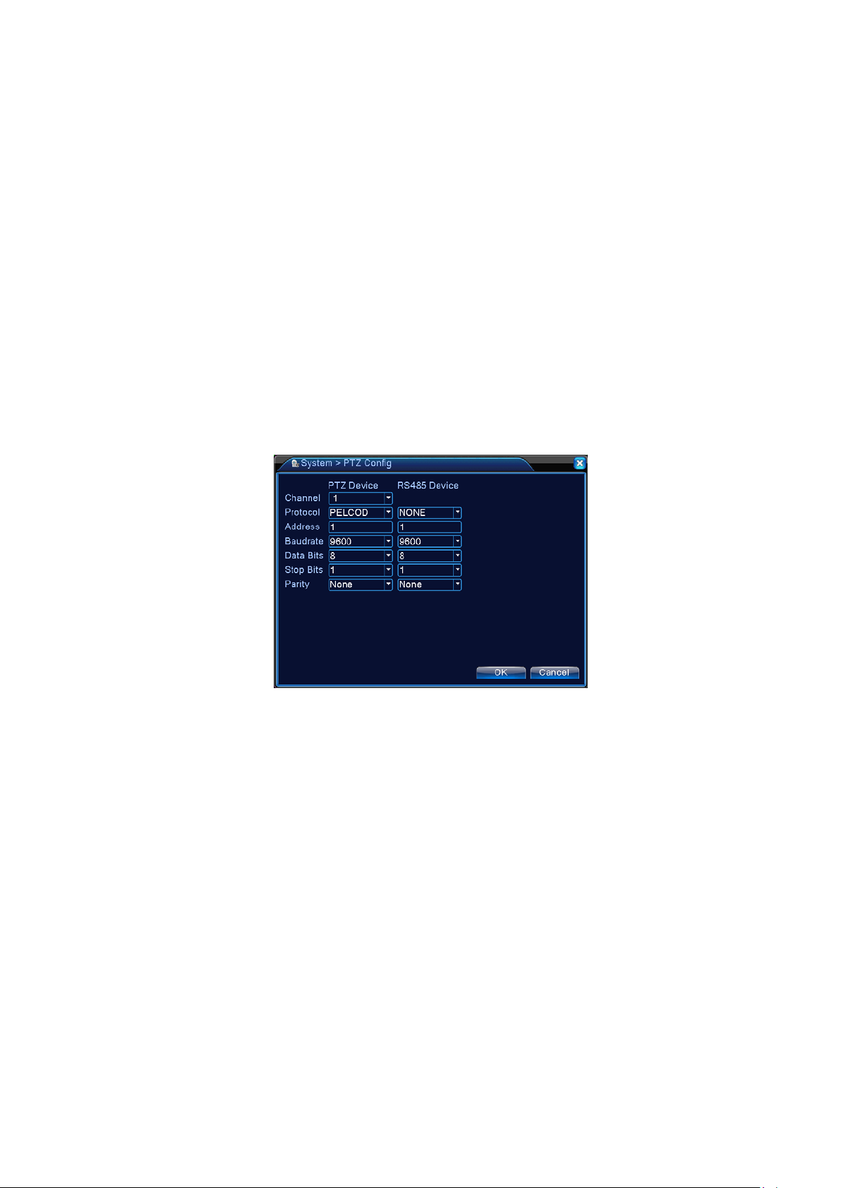
【Channel】Select input channel for dome camera;
Figure 4.32 PTZ Settings
【Protocol】Select proper dome camera protocol for corresponding brand and model (e.g.:PELCOD)
【Address】Set address for the corresponding dome camera. The default is 1 (Note:The address set
here must match the dome camera address or the dome camera cannot be controlled);
【Baud Rate 】 Selec t the dom e c am era b aud r ate t o contr ol PT Z and c am era on the correspondi ng
channel. The default is 115200;
【Data Bits】Available options: 5-8. The default is 8 bits;
【Stop Bits】Two options are 1 and 2. The default is 1;
【Parity】Includes odd parity, even parity, parity flag, none parity. The default is None.
4.4.7 Serial Port Settings
Figure 4.33 Serial Port Settings
Page 49
Page 50

【Function】 Or dinar y serial port is used for serial debug and upgrad e, as well as certain serial port
peripherals;
【Baud Rate】Select the appropriate baud rate length;
【Data Bits】Available options: 5-8;
【Stop Bits】Two options are 1 and 2;
【Parity】Includes odd parity, even parity, parity flag, none parity.
4.4.8 Auto Sequence Settings
Set screen auto sequence display . Highlight to enable the mode. Available selections include single
mode auto sequence such as single screen, 4-screen, 9-screen, and 16-screen or mixed mode auto
sequence.
Figure 4.34 Auto Sequence Settings
【Interval】Set time interval for auto sequence screen switch. Setting range is 5-120 seconds;
【Return AfterFinnished】When alarm ends, return to multi-screen preview
Note:In preview mode, click the icons
sequence(
4.5 Management Tools
Management Tools menu i ncludes: Disk M anagement, User M anagement, Online Users, Output
Adjustment, Auto Maintenance, Restore Default, System Upgrade, and System Information.
4.5.1 Channel Management
indicates the auto sequence is on, and indicates off).
*Remark:all series product support this function.
Digital manage including digital channel, channel status, and channel mode
(Remark: there is only analog mode if device is under full analog mode):
/ on upper right corner of the page to turn on/off the auto
Page 50
Page 51
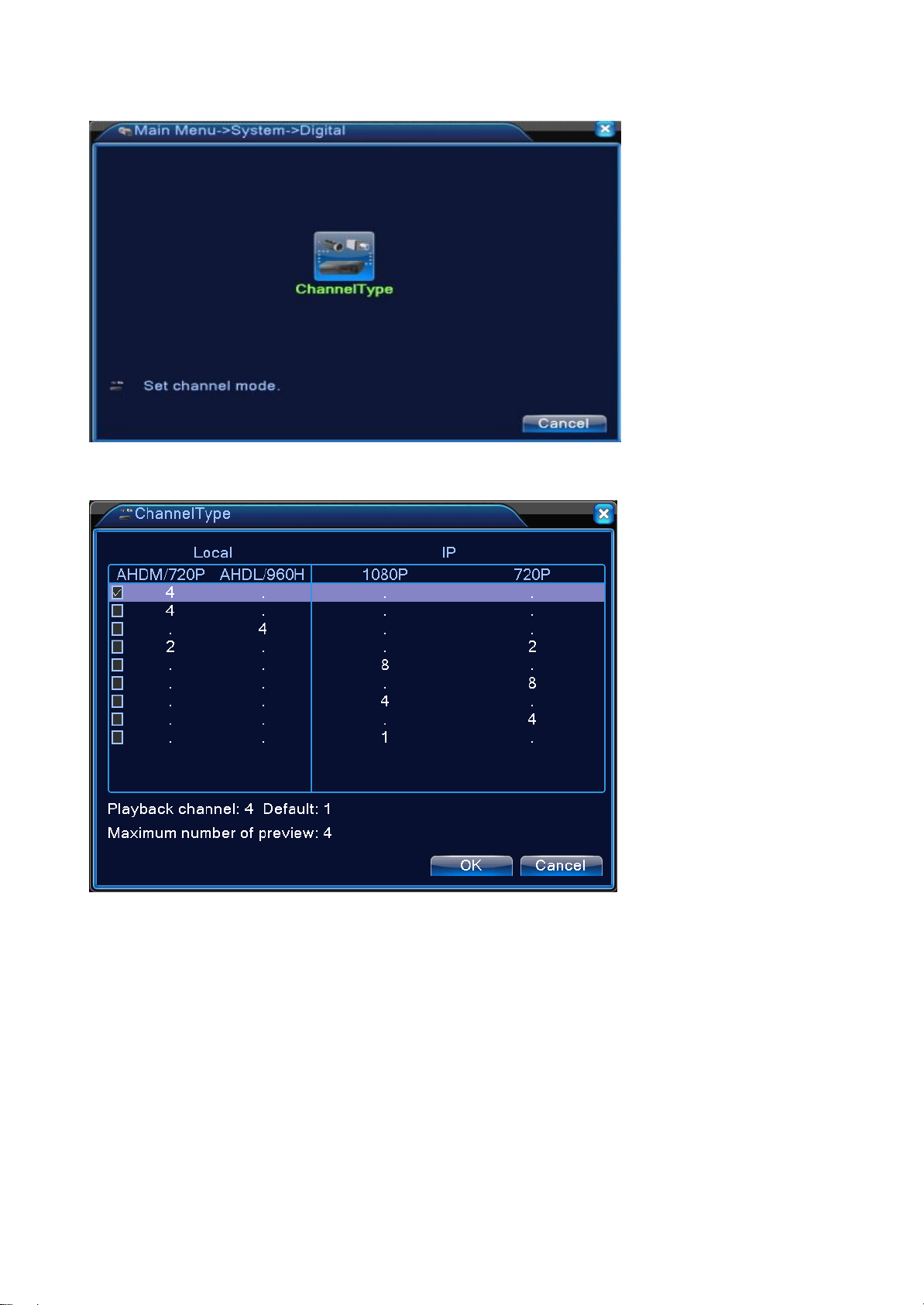
Channel mode:
Pic — 4.35channel manage interface
Remark: this series of product with full analog channel mode, hybrid mode and full
digital mode , and different model wi th different channe l mod e, u ser can shift the mode
freely if necessary.
4.5.2 Hard Drive Management
Hard Dri ve C onfiguration. T he menu shows c urrent disk information inc luding the number o f disks
connected, access interfac e, type, status, and aggregate capacit y. Hard Drive Operation, i ncluding: set
read/writ e disk, read-onl y disk, redundan t disk, di sk form at, and error r ecovery. Select the hard dri ve and
click the functional keys on the right side to execute.
Note: Read/Write Disk: May read and write data;
Snapshot Disk: Image storage disk. May read and write data;
Read-only Disk: The device can only read data from but not write onto the disk;
Page 51
Page 52

Redundant Disk: If there are already read/write disks, redundant disks will duplicate the video files.
Figure 4.36 Hard Drive Managment
4.5.3 User Management
Manage local user permissions.
Note: 1. All of the below us er names and group names may have a ma ximum of 8 char acters. T he
beginning and the end of the string cannot be left blank while spaces are allowed between
character s. Legitimate characters: Alphabet letters , numbers, undersc ores, hyphens, and dots .
Other characters are not allowed;
2. Ther e are no limit to the number of users and groups. Us er groups can be added or deleted
based on us er's need: Fac tory default has tw o levels: us er\admin. User can set his own gr oup
attributes. Members of a group can specify any functional rights permitted in the group;
3. User Management adopts group and us er two-l evel structure. T he group and the us er cannot
share the same name. Each user must belong to a group and only to one group.
Figure 4.37 Us er Managem ent
【Modify User】Modify th e attr i butes of an exis ting user ;
【Modify Group】Modify the attri bu tes of an existi ng user grou p;
Page 52
Page 53

【Modi fy P as sw ord 】Modif y user pas sword. P asswor d can b e set to 1-6 letters. The
begi nning and end of th e pass word cannot b e left bl ank while s paces are all owed b etween
letters.
Note: User with administrator rights is able to change not only his own password but also
other users' passwords.
Figure 4.38 Modify Password
【Add User】Add gr oup m em bers and s et user p erm i ssi on as shown i n Fi gur e 4.31. Enter Add User
menu, input user name and pass word, sel ect the belonging group, and sel ect wheth er the n ame c an be
shared. Shared means that the account can be used by multiple users simultaneously.
Once the bel onging gr oup is s elec ted, the us er per m i ss ion c an only be a subs et of that gr ou p. It c an
not overpass the permission attribute of the group.
For the convenience of user management, we recommend setting the permission for regular users at a
lower level than for advanced users.
Figure 4.39 Add User
Page 53
Page 54

【Add Group】Add a new user group and set group permissions as shown in Figure 4.32. There are 36
permission items to choose from, including Device Shutdown, Live Surveillance, Playback, Recording
settings, Video Backup, etc.
Figure 4.40 Add Group
【Delete User 】Del ete e xisting us er. In Fi gure 4 .29, s el ect the us er t o b e dele ted. C li c k Delete Use r
button;
【Delete Group】 Delete existing group(make sure there is no user in the group). In Figure 4.29, click
Delete Group button to show Figure 4.33. Select the group to be deleted and click Delete button.
Figure 4.41 Delete Group
4.5.4 Online User
View information on the network users connected to the local DVR. You may also disconnect the
selected network users(by tick √ in checkbox). The account will be frozen until the next reboot.
Page 54
Page 55

Figure 4.42 Online User
4.5.5 Output Adjustment
Same as “3.5.7 Output Adjustment”.
4.5.6 Auto Maintenance
User can s et t hei r ow n sc hedul e to au tom ati cal l y restart the system and delet e the fi l es w ith s et ti m e
limit.
Figure 4.43 A uto Mai ntenance
【Auto On/Off Time】:Set timer to automatically turn on and off the DVR.
4.5.7 Restore Default
Restore the system to factory default configuration (may select in the menu specific items that need be
restored).
Page 55
Page 56

Figure 4.44 Restore Default
4.5.8 System Upgrade
Figure 4.45 System Upgrade
【Upgrade Position】Select USB interface;
【Upgrade File】Select the file being upgraded.
4.5.9 Device Information
Provide device information on DVR interface for clients' convenience
Page 56
Page 57

Figure 4.46 Device Information
4.5.10 Import/Export
Export current log setting,import the new setting.
Figure 4.47 Import/Export
4.6 System Information
Display DVR information on: Hard drive, Streaming statistics, Log, and Version Information.
4.6.1 Hard Drive Information
Display the status of the installed hard disk, including the ty pes of the disks, aggregate size, free space,
and recording time.
Page 57
Page 58

Figure 4.48 Hard Drive Information
Tip: In H ard Dr i ve Infor m ation, ○ means the dis k works proper l y, X indicates a fai l ure, and – means
not installed. If the user needs to repl ace a bad dis k, shut down the de vice befor e removing the bad di sk
and install the new one.
An asterisk “*” after the disk number indicates that it is the current work disk (e.g., 1*). If the
corresponding disk is damaged, there will be only "?" marks in the information.
4.6.2 BPS
demonstrates the change in streaming.
Live display video stream (Kb/S) on the channel and disk space used (MB/H). The oscillogram
Figure 4.49 BPS
4.6.3 Log
View system log based on the search method setup.
Page 58
Page 59
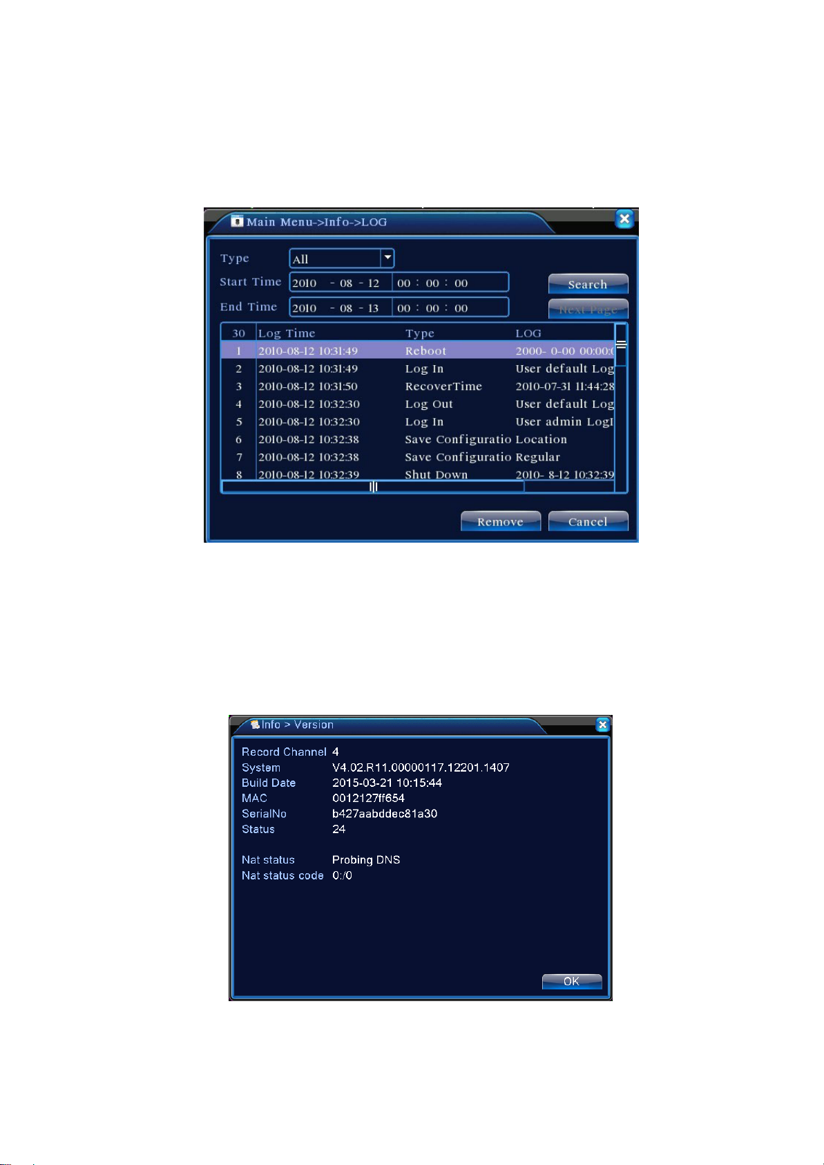
Log is categor ized into: s ystem operation, configuration, data mana gement, alar m event, recordi ng
operation, user management, and fi le management. To search the log by time peri od, press the Search
button. The s ystem wi ll dis play the log in table for mat (eac h page contains 128 lines ). Press Page Up or
Page Down to turn the page and Clear to empty all logged information.
Figure 4.50 Log
4.6.4 Version Information
Show basi c infor mati on on the de vice, inc luding har dware infor mation, s oftwar e version an d releas e
time.
Figure 4.51 Version Information
Page 59
Page 60

4.7 System Shutdown
See Chapter “3.18 System Shutdown”.
Page 60
Page 61

Chapter 5: Cloud Technology Basic Operation
5.1 Cloud technology monitor
Cloud technology make the device one step on net, greatly bring convenience for customer to
monitor via wide area network, this technology is using the serial no to visit device.
*Remark:the device that using cloud technology should be in the WAN( Wide Area
Network ) firstly.
� Check the connecting status of cloud technology
Connect device to WAN firstly, then enter
successfully connect to the cloud server or not.
【Main
menu】>【Info】>【Version】to
check whether the device
Connect failed interface successfully connect
Pic 5.1 cloud technology server connection
status
interface
� Log in cloud server
Visit http://xmeye.net to see below log in page, it devided into two mode: by user and by device,
user can base on their need to log in freely.
*Remark: to log in “by user”, the user need to register at the first time.
Page 61
Page 62
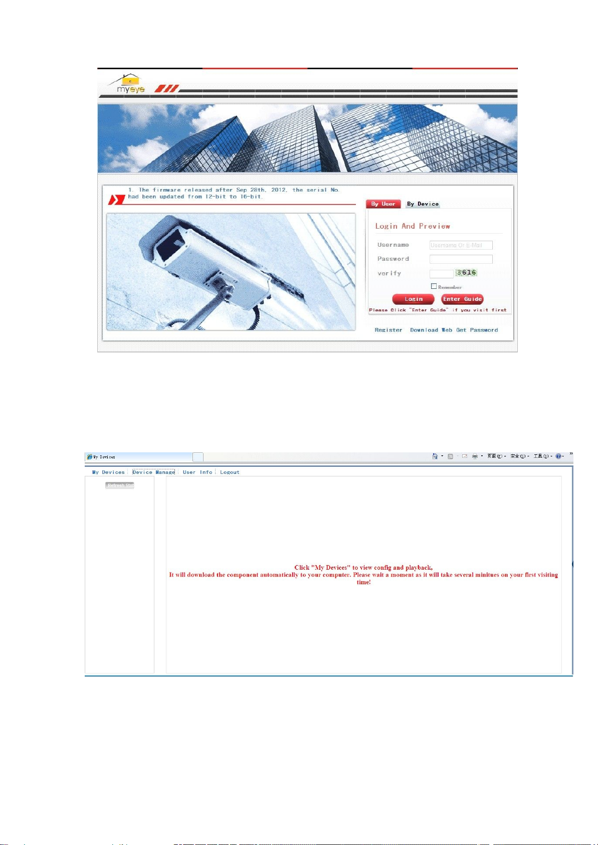
Pic.5.2 Log in by cloud server
� Log in by user
Customer use their registered user name and password to log in, will see below
interface
Pic 5.3 cloud technology operation interface
Device manage
Mainly use to add device, click “add”to add the serial number of device to be monitored.
Page 62
Page 63

Pic 5.4 device manage
interface
Pic 5.5 add interface at device
manage
*Remark:in pic 5.5, the user name means the user name of monitored device,
means the password of related
user.
password
My Device
Mainly show all the added device here, click the on-line device name, can access to control this
device accordingly.
Page 63
Page 64

*Remark:the icon of“ ” means offline, the device do not connect to server
� Log in by device
Pic 5.6 monitor page - log in by
user
successfully.
Page 64
Page 65

Pic 5.7 interface of log in by
device
Input the serial number of device and the verify code to monitor and control the device directly.
Pic: 5.8 monitor page - log in by
device
Page 65
Page 66

Chapter 6 F AQ and Ma intenance
、
、
、
、
6.1 FAQ
headquarters for assistance. We are more than happy to assist.
1
If you encounter a pr oblem not lis ted below, please contact your l ocal c ustomer service or call our
Q: DVR will not start after power-on
A: Possible cause:
1 Input power is not correct
2 Switching power supply has bad wire connection
3 Switching power supply is damaged
4 Upgrade error
5 Damaged hard drive or hard drive cable
6 Front panel failure
7 DVR motherboard failure
2
Q: DVR restarts automatically few minutes after being turned on or freezes frequently
A: Possible cause:
1 Input voltage unstable or too low
2 Hard drive has bad tracks or damaged cable
3 Switching power supply has insufficient power
4 Front-end video signal is unstable
5 Poor ventilation; excessive dust; poor operating ambience
6 DVR hardware failure
3
Q: Hard drive not detected after startup
A: Possible cause:
1 Hard drive cable is not connected
2 Hard drive cable is damaged
3 Hard drive is damaged
4 Bad motherboard SATA port
4
Q: No video output on one or more channels
Page 66
Page 67

、
、
、
、
A: Possible cause:
1 Program not compatible. Re-upgrade with right program
2 Image brightness becomes 0. Restore default settings
3 No v ideo signal input or signal too weak
4 Has channel privacy mask (or screen view blocker) set up
5 DVR hardware failure
5
Q: Real-time vide o problems, such as severe distortion on vide o color and brightness.
A: Possible cause:
1 When using BNC output, if NTSC and PAL format selection is incorrect, video image
becomes black and white
2 DVR and monitor impedance mismatched
3 Video tra ns m iss ion di stance i s too far or video signal atte nuates to o m uc h in tr ans m ission
line
4 DVR color and brightness settings are incorrect
Q: Local playback search finds no video
6
A: Possible cause:
1 Hard drive cable or jumper error
2 Hard drive is damaged
3 Upgraded with a program different to the original program in the system
4 The video being searched has already been overwritten
5 Recording function is not turned on
7
Q: Local search returns blurred video
A: Possible cause:
1 Video quality setting is too low
2 Progr am data read error ; Video stream ing very low; Ful l screen m osaic during pla yback.
Usually DVR will return to normal after restart
3 Hard drive cable and jumper error
4 Hard drive malfunction
5 DVR hardware failure
8
Q: No sound in monitoring
Page 67
Page 68

A: Possible cause:
、
、
、
1 Not equipped with active pickups
2 Speakers not switched on
3 Audio cable damaged
4 DVR hardware failure
9
Q: Audio in monitoring but none in playback
A: Possible cause:
1 Setup error: audio option is not turned on
2 Corresponding channel is not connected to video. Video plays back intermittently with blue
screen
10、 Q: Time display is not correct
A: Possible cause:
1 Setup wrong.
2 Bad battery connection or power low
3 Crystal resonator not working properly
11
Q: DVR cannot control PTZ
A: Possible cause:
1 Front-end PTZ malfunction
2 PTZ decoder settings, wiring, or installation is incorrect
3 Incorrect cable wiring
4 PTZ settings in DVR are incorrect
5 PTZ decoder and DVR protocol do not match
6 PTZ decoder and DVR address do not match
7 When connected with multiple decoders, PTZ decoder needs to add a 120 ohm resistance
to elimi nate the refl ec tion and impedanc e m atchi ng between the far ends of A/B c ables , or
PTZ control will be unstable
8 Distance too far
12
Q: Motion detection does not function
A: Possible cause:
1 Time period settings are not correct
Page 68
Page 69

2 Incorrect settings for motion detecting areas
、
、
、
、
3 Sensitivity sets too low
4 Hardware of certain versions have limits
13
Q: Cannot log in from client end or through WEB
A: Possible cause:
1 Client cannot install or normally display whether the OS is Win98 or Win me: We
recommend upgrading to version Win2000 SP4 or higher, or installing an earlier version of
the customer software.
2 ActiveX control is disabled
3 Version dx8.1 or higher is not installed. Upgrade video card driver
4 Network connection error
5 Network setup error
6 Incorrect user name and password
7 Version of client software does not match the program version of DVR
14
Q: No video image or only mosaic on network preview and video playback screen
A: Possible cause:
1 Insufficient network bandwidth
2 Client’s PC may have resource constraints
3 DVR may have the area masked or privacy protection on the channel
4 The user logged in has no monitoring permission
5 The quality of the real-time DVR video output is poor
15
Q: Unstable network connection
A: Possible cause:
1 Unstable network
2 IP address conflict
3 MAC address conflict
4 Bad network card in PC or DVR
16
Q: Burn/USB backup error
A: Possible cause:
Page 69
Page 70

1 Burner shares the same cable with hard drive
、
、
、
、
2 Excessive amount of date occupies too much CPU resource. Stop recording before backup
3 The amount of data exceeds the device capacity and results in burn error
4 Incompatible backup device
5 Backup device damaged
17
Q: Keyboa rd cannot control DVR
A: Possible cause:
1 DVR serial port settings are incorrect
2 Address incorrect.
3 Insufficient power to support multiple transformers. Need to provide separate power supply
to each transfer.
4 Transmission distance is too far
18
Q: Cannot disarm the alarm signal
A: Possible cause:
1 Alarm settings are incorrect
2 Alarm output turned on manually
3 Input device malfunction or incorrectly connected
4 Problem with certain versions of the program. Upgrade the program to solve problem.
19
Q: Alarm is not functioning
A: Possible cause:
1 Alarm settings are incorrect
2 Incorrect alarm cable wiring
3 Incorrect alarm input signal
4 The alarm device is connected to two loop circuits simultaneously
20
Q: Remote control is not functioning
A: Possible cause:
1 Remote control address incorrect
2 Remote control is out of operating range or angle
3 Battery in the remote control is out of power
4 Remote control or DVR front panel is damaged
Page 70
Page 71

、
、
、
、
Q: Saved recording is short
21
A: Possible cause:
1 Excessive streaming due to poor quality of front-end camera, dirty lens, camera installed in
backlight, or incorrect aperture adjustment
2 Insufficient hard drive capacity
3 Damaged hard drive
Q: Downloaded file will not play
22
A: Possible cause:
1 Media player is not installed
2 No graphic accelerator software version DX8.1 or higher is installed
3 PC does not have DivX503Bundle.exe plugin installed to playback in MEDIA PLAYER after
the file is converted to AVI format
4 winxp OS needs to install plugins DivX503Bundle.exe and ffdshow-20041012.exe
23
Q: Forget password for advanced l ocal menu or network operation
A: Solutions:
1 Please contact your local customer service or our headquarters for assistance. We can
help you to fi nd the sol ution bas ed on the d evice m odel and program vers ion infor mati on
that you provide.
24
Q: Can not see the preview picture the digital channel
A: Solutions:
1 Did not add device
2 The device of related channel was not enable
3 The device of related channel was not selected.
4 The selected device did not connect to video sources
5 The channel title of selected remote device is not exist.
6 Stream for remote channel was set by extra stream.
7 User name & password not matched
8 directly input with IP address or port No. incorrectly when adding device.
9 The resolution of added device is too large to display by the monitor.
25、 Q: Click “search” why not search out any of the device.
Page 71
Page 72

、
A: Solutions:
1 There is no other device exist in the local area network
2 The subnet mask setting incorrectly on Network settings.
Q: The snapshot at alarm function was enable, why not catch picture
26
A: Solutions:
1 HDD manage without partition for snapshot.
2 Partition for snapshot is 0.
3 The snapshot function is not enable on record -> storage of related channel.
27、 The time shows on digital channel is not the same as local side:
Enable the time synchronous function of digital channel.
28、 Can not see preview picture of analog channel
A:Solutions
1 The camera did not connect to video interface
2 The device did not connect to video source
3 Video source is broken.
29、Picture will be frozen when multi-connection and shift devices.
Picture come out from digital channel need few seconds, shift device means to show new picture,
so it needs several seconds to buffer.
:
Page 72
Page 73

6.2 Mai ntenance
1 In a dam p en vironm ent, dus t o n ci r cui t board m ay resul t i n shor t cir cuits, affect the normal
operation of the D VR, and even dam age the DVR. For long-term stable operat ion of the
DVR, brush off the dust on the circuit board, connectors, fans, and DVR case regularly.
2 Keep the equipment well grounded to avoid the interference to video/audio signal and
protect the DVR from damage caused by static or induced voltage.
3 Do not pl ug/unplug A/V cabl e, RS-232, and RS-485 wi th the power on, or i t could easil y
damage these ports.
4 If pos sible, do not use T V set on DVR’s local video output ( VOUT ). Otherwise, it could
easily damage the video output circuit in DVR.
5 Do not turn o ff the power switc h to shutdow n the D VR. Use t he shutdow n fun ction i n the
menu, or on/off button on the fron t panel (hol d it down for 3 s econds) to turn off the DVR
power automatically and prevent damage to the hard drive.
6 Keep the DVR away from heat sources or hot lplaces.
7 Keep the area around the DVR well ventilated.
Regular system inspection and maintenance are required.
Page 73
Page 74

Appen di x 1. Mouse Op er at i ons
*
*
This document uses the mouse with a right-hand ed configur a tion as
This device supports a mouse with USB interface.
Operation Functions
During playback, double click a file in the video list to replay.
Left double
click
Left click
mouse
Right click
mouse
Double click on the playback image to zoom in or out of the screen
During pre view, double cl ick a channel to di spl ay it in ful l screen. Doubl e c lic k
again to return to multi-screen
Select corresponding function in menu page
Pops up desktop quick launch menu in preview page
Quick launch menu for current function during menu operation
an example
Scroll Wheel
Mouse
Movement
Mouse Drag
Turn the mouse scroll wheel to increase/decrease value in a number box
Switch among options in combo box
Page up or down in list box
Select the contr ol under current coordinates or an item within the control to
move it
Set areas for motion detection
Set areas for surveillance coverage
Page 74
Page 75

Appendix 2. Hard Drive Capacity Calculation
When i nstalling the DVR f or the first time, make sure wheth er the DVR has i nternal hard drives
mounted. Pay attention to the jumper when installing an IDE hard disk;
1、 Hard disk capacity
The DVR sets no limit on hard disk capacity. Choose a disk 10G or more. For better
operation stability, we recommend the use of hard disks ranging from 120G~250G.
2、 Choose the aggregate capacity of the hard disks
Formula for calculating the capacity of a hard drive:
To tal hard drive capacity(M)= number of channels × recording time desired (in Hours) × use of
disk space each hour (M/Hour)
Similarly, we can derive a formula for calculating recording time:
Recording Time (Hour) =
The DVR uses MPEG4/H.264 compression technology and has a wide dynamic range. When
calculating the hard disk capacity, it should use the estimated size of the files generated each hour
on each channel based on bit stream statistics.
For example:
Using a 500G hard drive and recordi ng in real-tim e CIF quality can sustain appro ximately 25
days. Use of hard di sk space per hour for recordi ng on a single channel is 200M/Hour. When
recordi ng 24 hours continuous ly in real-ti me CIF quali ty on 4 channel s, the da ys it can las t are:
500G/(200M/H X 24 hours X 4 channels) = 26.
Use of disk space each hour (M/Hour) × number of channels
Total HD Capacity (M)
Page 75
 Loading...