

SmartVM KVM-SW-8/16, KVM-SW-8, KVM-SW-16 User Manual

SmartVM
23900 Mercantile Road
Cleveland, Ohio 44122
Tel # 1-866-999-3210, Fax # 1 -216-765-0548
Internet : www.smartvm.com Mail : sales@smartvm.com
User
Manual
KVM-SW-8/16
1RU Rackmount USB KVM Switch

Rev. : 0.1 P.1
KVM-SW-8/KVM-SW-16 User Manual
1.Table Of Content
1. Table of Content
P.1
2. Read Before Installation
P.2
3. Introduction
P.3
4. Features
P.3
5. Package Contents
P.4
6. Optional Accessories
P.5
7. Peripheral products
P.5
8. Important Safeguard
P.6
9. Structure Diagram
P.7
10. Dimension Diagram
P.8
11. KVM Session
Front View
P.9
Rear View
P.10
Installation Steps
P.11
Cascading
P.12
12. Start Up
P.13
Hot Key Command
P.13
Hot Key Operation
P.14-15
OSD Operation
P.16-22
13. FAQ
P.23
14. Technical Specification
P.24

Rev. : 1.1 P.1
KVM-SW-8/KVM-SW-16 User Manual
2 . Read Before Installation
Technical Notes
For Windows 98/98 SE systems
●
HID (Human Interface Device) driver must be installed
prior
to using
the USB KVM switch. To install the HID driver, first connect a USB
keyboard and mice directly to computer (before installing KVM switch)
then follow theWindows installation instructions, this will install the HID
device driver and allow the use of the KVM switch.
Note :
Failure to do so may result in Windows not being able to detect
keyboard and mouse.
●
If a mouse recognition error is displayed during system boot:
“Windows did not detect a mouse attached to the computer.You can
safely attach a serial mouse now. To attach a mouse to a PS/2 mouse
port, you must first turn the computer off”
a) Press the
Tab
key once to select the check box.
b) Press the
Space bar
once which will place a check in the box
“Do not show this message again”
c) Press the
Enter
key once and Windows will continue to boot and
will then recognize the mouse.
Operating System Compatibility
●
Any USB-enabled operating system such as Windows® 98,
Windows® 98SE, Windows® 2000, Windows® XP or higher.
●
Windows® 95 are not recommended because of immature USB
support.

Rev. : 1.0 P.3
KVM-SW-8/KVM-SW-16 User Manual
3. Introduction
As the server density increases, you run out of spaces in racks and server
room quickly. CV Series USB KVM Switch is slim 1U form factor to provide
effective assistant for an administrator to control multiple PCs
All models are OSD (On-Screen-Display) menu equipped to simply the server
management. It fit different applications and can be cascaded together
expanding the capacity up to 128 computers, and providing the maximum
flexibility.
4. Features
●
Multi-platform
- Mix PCs, SUN Microsystems, IBM compatibles,
HP, Compaq and Dell.
●
Hot Pluggable
- Add PCs or remove connected PCs for
maintenance without powering down the USB
KVM switch or PCs.
●
No S/W required
- Easy PC selection via on screen display manual,
push buttons and hot-key.
●
Built-in microprocessor emulation for each port boots up process.
●
High video quality with up to 1,920 x 1,440 and 200MHz bandwidth.
●
Name servers up to 16 characters long.
●
Scan mode with Monitor servers at intervals 5 to 99 seconds.
●
Support eight characters password protection and search PC server name.
●
VGA and USB two-in-one by 15pin HDDB connector at KVM side.
●
Cascade for use up to 128 servers.
Disclaimer
This information is subject to change without notice. The producer of thismanual accepts no
responsibility for damage or claims, resulting from misuse or misinterpretation.

Rev. : 1.0 P.4
KVM-SW-8/KVM-SW-16 User Manual
5. Package Contents
US B KV M Switch
1 Pi eces
User’s manual
1 Pi eces
DC Power A dap ter
1 Pi eces
19 ” Mounting Bracket
1 Pair
Before Unpacking
It is very important to locate the USB KVM switch in a suitable environment.
1. The surface for placing and fixing USB KVM switch should be stable and
level or mounted into a suitable cabinet.
2. Make sure the place is ventilated and out of direct sunlight, away from
sources of excessive dust, dirt, heat, water, moisture and vibration.
3. Convenience for connecting USB KVM switch to the related facilities
should be well considers too.
Unpacking
The USB KVM Switch comes with the standard parts shown as above. Check
and make sure they are included and in good condition. If anything is
missing, or damage, contact the supplier immediately.
Rev. : 1.0 P.5
KVM-SW-8/KVM-SW-16 User Manual
6. Optional Accessories
KVM Cable
CB-6 / 10 / 15 6ft / 10ft / 15ft PS/2 3-in-1 cable
Cascade Cable
????
7. Peripheral Products
Description
CAT.5 USB KVM extender
1U 15” LCD Monitor Drawer
6U(15") / 7U(17") / 8U(19") LCD Monitor
1U LCD Keyboard Drawer

Rev. : 1.0 P.6
KVM-SW-8/KVM-SW-16 User Manual
8. Important Safeguards
Please read all of these instructions carefully before you use the device.
Save this manual for future reference.
●
Unplug the USB KVM switch from the power outlet before cleaning.
●
Do not sprayliquid cleaners or aerosol directly on the device.Wet a cloth with
a neutral detergent (e.g. clean water) and squeeze it tight, then clean the
screen slightly with it.
●
Do not expose the USB KVM switch directly to rain, water, moisture or
sunlight.
●
Do not attempt to service the device yourself. Improper operation may void
your warranty. Refer all servicing to qualified service personnel.
●
Safe storage environment of the PS/2 KVM switch is ranging between –20oC
and 60oC. Permanent damage could occur if the USB KVM switch is stored
outside the safe range.
●
Unplug the keyboard drawer with USB KVM switch immediately and call a
qualified service personnel under the following conditions:
1. If the USB KVM switch has been exposed to rain, liquid or water.
2. If the USB KVM switch has been dropped or the casing has been
damaged.
What the warranty does not cover
1. Any product, on which the serial number has been defaced, modified or
removed.
2. Damage, deterioration or malfunction resulting from:
a) Accident, misuse, neglect, fire, water, lightning, or other acts of nature,
unauthorized product modification, or failure to follow instructions supplied
with the product.
b) Repair or attempted repair by anyone not authorized by us.
c) Any damage of the product due to shipment.
d) Removal or installation of the product.
e) Causes external to the product, such as electric power fluctuation or failure.
f) Use of supplies or parts not meeting our specifications.
g) Normal wear and tear.
h) Any other causes which does not relate to a product defect.
3. Removal, installation, and set-up service charges.
Rev. : 1.0 P.7
KVM-SW-8/KVM-SW-16 User Manual
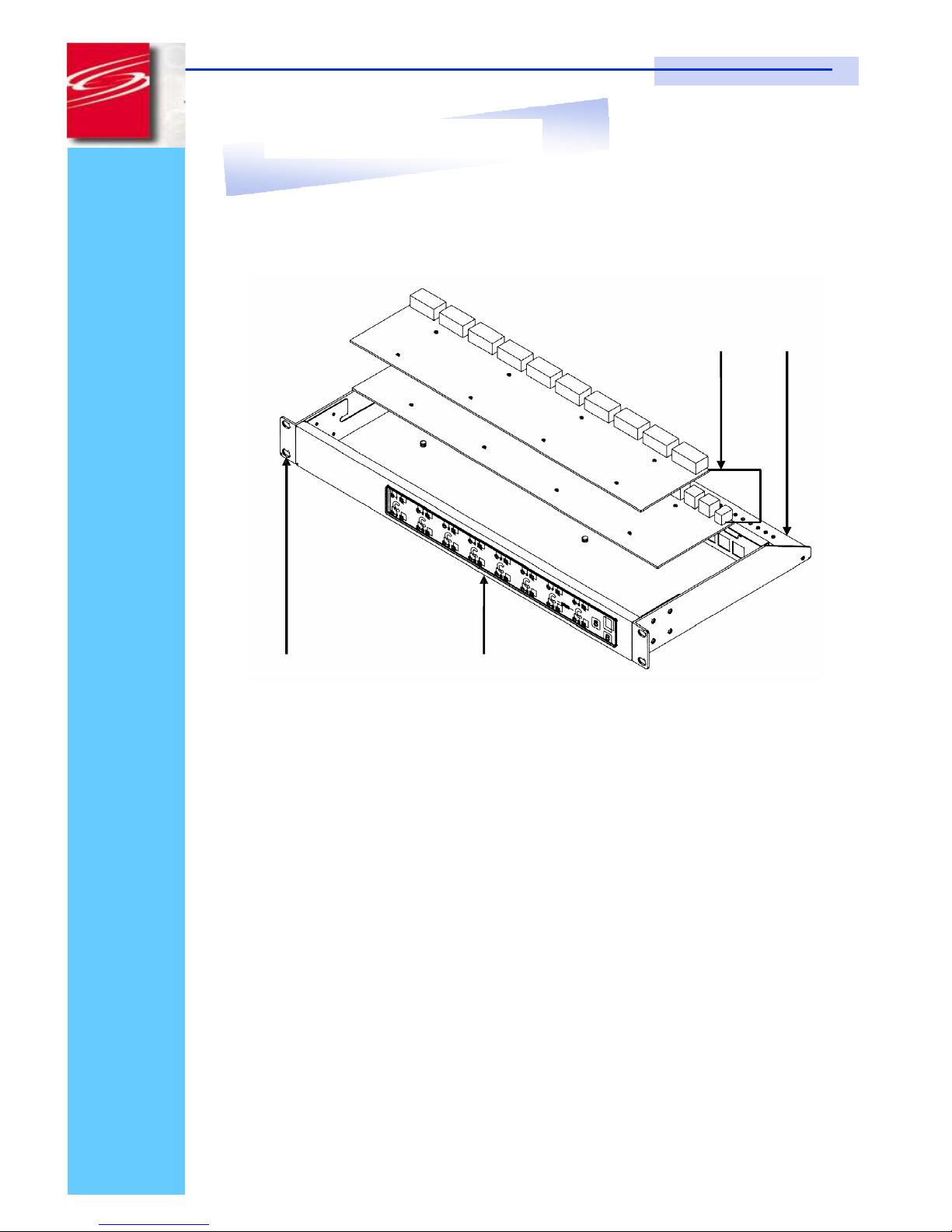
9. Structure Diagram
1.
USB KVM Switch
2.
Cable Mounting Kit
3.
19” Mounting Kit
4.
KVM Membrane
 Loading...