

Installation Guide Smart-UPS™
750/1000/1500/2200/3000 VA 120/208/230 Vac
Rack-Mount 2U
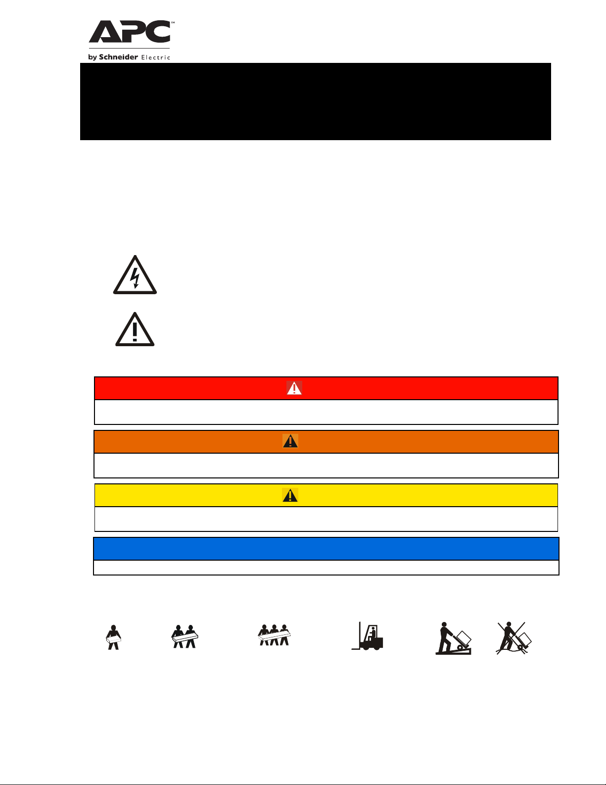
Safety Messages
SAVE THESE INSTUCTIONS - This manuals contains important instructions that should be followed during
installation and maintenance of the Power Management Unit, Service Bypass Unit and batteries.
Read the instructions carefully and look at the equipment to become familiar with the device before trying to install,
operate, service or maintain it. The following special messages may appear throughout this document or on the
equipment to warn of potential hazards or to call attention to information that clarifies or simplifies a procedure.
The addition of this symbol to a Danger or Warning product safety label indicates that an
electrical hazard exists that will result in personal injury if the instructions are not followed.
This is the safety alert symbol. It is used to alert you to potential personal injury hazards. Obey all
safety messages that follow this symbol to avoid possible injury or death.
DANGER
DANGER indicates a hazardous situation which, if not avoided, will result in death or serious
injury.
WARNING
WARNING indicates a hazardous situation which, if not avoided, could result in death or serious
injury.
CAUTION
CAUTION indicates a hazardous situation which, if not avoided, could result in minor or moderate
injury.
NOTICE
NOTICE is used to address practices not related to physical injury.
Product Handling Guidelines
<18 kg
<40 lb
18-32 kg
40-70 lb
32-55 kg
70-120 lb
>55 kg
>120 lb
Safety and General Information
su04
Inspect the package contents upon receipt. Notify the carrier and dealer if there is any damage.
Read the Safety Guide supplied with this unit before installing the UPS.
• Adhere to all national and local electrical codes.
• This UPS is intended for indoor use only.
• Do not operate this UPS in direct sunlight, in contact with fluids, or where there is excessive dust or
humidity.
• Be sure the air vents on the UPS are not blocked. Allow adequate space for proper ventilation.
• The battery typically lasts for two to five years. Environmental factors impact battery life. Elevated ambient
temperatures, poor quality utility power, and frequent short duration discharges will shorten battery life.
• Connect the UPS power cable directly to a wall outlet. Do not use surge protectors or extension cords.
• The equipment is heavy. Always practice safe lifting techniques adequate for the weight of the equipment.
• The batteries are heavy. Remove the batteries before installing the UPS and XLBP in a rack.
• Always install external battery packs (XLBPs) at the bottom in rack-mount or stack configurations. The
UPS must be installed above the XLBPs.
• Always install peripheral equipment above the UPS in rack-mount or stack configurations.
• The UPS will recognize as many as 10 external battery packs connected to the UPS. However there is no
limit to the number of XLBPs that can be used with the UPS.
• The model and serial numbers are located on a small, rear panel label. For some models, an additional label
is located on the chassis under the front bezel.
• Always recycle used batteries.
• Recycle the package materials or save them for reuse.
FCC warning
This equipment has been tested and found to comply with the limits for a Class A digital device, pursuant to part 15
of the FCC Rules. These limits are designed to provide reasonable protection against harmful interference when the
equipment is operated in a commercial environment. This equipment generates, uses, and can radiate radio
frequency energy and, if not installed and used in accordance with the instruction manual, may cause harmful
interference to radio communications. Operation of this equipment in a residential area is likely to cause harmful
interference in which case the user will be required to correct the interference at his own expense.
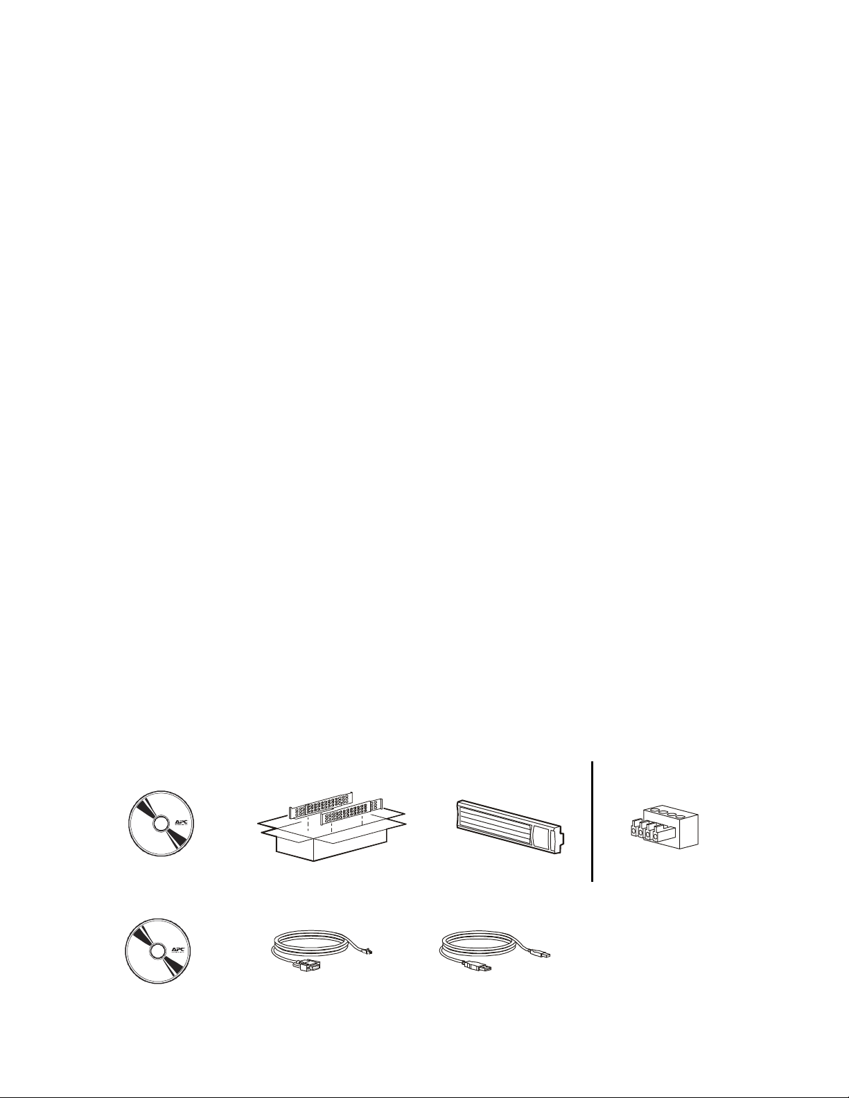
Inventory
All models 2200/3000 VA models
34a
(1)
120/208/230 Vac models
(1)
(1)
(1)
(1) (1) (1)
Smart-UPS 750/1000/1500/2200/3000 VA 120/208/230 Vac Rack-Mount 2U2

230 Vac models
(2)
(1) 2200/3000 VA models
(1) 2200/3000 VA models
(1) 2200/3000 VA models
Installation
CAUTION
RISK OF DROPPED OR FALLING EQUIPMENT
• The equipment is heavy. Always practice safe lifting techniques adequate for the weight of the
equipment.
• Remove the battery before installing the UPS in a rack.
• When installing equipment in a rack, always install the UPS at the bottom of the rack with the peripheral
equipment above the UPS.
• The UPS should always be installed below peripheral equipment in stack or rack configurations.
Failure to follow these instructions can result in equipment damage and minor or moderate injury
CAUTION
RISK OF HYDROGEN SULPHIDE GAS AND EXCESSIVE SMOKE
• Replace the battery at least every 5 years.
• Replace the battery immediately when the UPS indicates battery replacement is necessary.
• Replace battery at the end of its service life.
• Replace batteries with the same number and type of batteries as originally installed in the equipment.
• Replace the battery immediately when the UPS indicates a battery overtemperature condition, or when
there is evidence of electrolyte leakage. Power off the UPS, unplug it from the AC input, and
disconnect the batteries. Do not operate the UPS until the batteries have been replaced.
• *Replace all battery modules (including the modules in External Battery Packs) which are older than
one year, when installing additional battery packs or replacing the battery module(s).
Failure to follow these instructions could result in equipment damage and minor or moderate
injury.
*Contact APC by Schneider Electric Worldwide Customer Support to determine the age of the installed battery
modules.
750 VA models
su0648 a
Smart-UPS 750/1000/1500/2200/3000 VA 120/208/230 Vac Rack-Mount 2U 3
su0649a

su0660 a
su0440 a
su
su0652a
su0659a
su0563 a
su0651a
bu059a
0469a
Smart-UPS 750/1000/1500/2200/3000 VA 120/208/230 Vac Rack-Mount 2U4

1000/1500 VA models
su0660a
su0440a
su
su0631 a
su0658a
su0630 a
su0657a
su0661a
0469a
su0629a
Smart-UPS 750/1000/1500/2200/3000 VA 120/208/230 Vac Rack-Mount 2U 5

2200/3000 VA models
su0660 a
su0440 a
su
su0656a
su0655a
su0630 a
su0654a
su0661a
0469a
su0629a
Smart-UPS 750/1000/1500/2200/3000 VA 120/208/230 Vac Rack-Mount 2U6

Overview and Start Up
su064
su062
su064
su06 25
su0626
Rear panel features
SmartSlot for optional NMC accessory card Outlets
UPS input EPO connector
Circuit breaker/Overload protection USB port
Controlled outlet group RJ45 connector - UPS monitoring serial port
Chassis ground screw
750/1000 VA 120 Vac
1500 VA 100/120 Vac 3000 VA 100/120 Vac
4a
750/1000/1500 VA 230 Vac 3000 VA 208 Vac
5a
2200 VA 120 Vac 2200/3000 VA 230 Vac
su0623a
4a
a
a
Smart-UPS 750/1000/1500/2200/3000 VA 120/208/230 Vac Rack-Mount 2U 7

Electrical connections
su0343a
A
Electric
CAUTION
RISK OF ELECTRIC SHOCK
• Adhere to all local and national electrical codes.
• Wiring must be performed by qualified electrician.
• Always connect the UPS to a grounded outlet.
Failure to follow these instructions can result in minor or moderate injury
Plug type and connector locations may vary.
su0628 a
Display panel features
Online LED
UPS
ON/OFF key
On Battery LED
Site Wiring Fault LED
Replace Battery LED
Display interface
UP/DOWN arrow keys
ENTER key
ESCAPE key
PC By Schneider
Controlled outlet groups
Some UPS models have one bank of outlets that can function as a controlled group. Use the display interface to
configure the controlled outlet features, navigate to:
Main Menu > Control > Outlet1 Control.
© 2018 APC by Schneider Electric. APC, the APC logo, and Smart-UPS are owned by Schneider
Electric Industries S.A.S., or their affiliated companies. All other trademarks are property of their
respective owners.
EN 990-3892E-001
8/2018
 Loading...