

Smart Tweezers ST5 User Manual
2 3
SmartTweezers_Manual_03.8.indd 2-3 10/14/2011
2:04:07
PM

TABLE OF CO
NTENTS
Notice
1
Warrant
y
1
Safety Precautions
2
Getting Starte
d
3
Overvie
w 3
Controls 6
P
ower O
n 7
M
enu Structures And Functions
9
Measurement Feature
s
20
Measuring Resistanc
e
20
Measuring Capacitance
20
Measuring Inductanc
e
21
Mainte
nanc
e
22
Labe
lling & Verification Requirement
s
23
Appen
dix A. Specifications
24
Appendix B. Default Settings
25
Appen
dix C. Accuracy Speci
ficatio
n
26
SmartTweezers_Manual_03.8.indd 5 10/14/2011
2:04:07
PM

NOTICE:To The besT of our knowledge This documenT is believed To be accuraTe.The manufacTurer reserves The righT T
o
change The informaTion and does noT a
ssume any responsibiliTy for omissions and/or errors found in This documenT.
WARRANTY: manufacTurer warranTs This pro
ducT To be free from defecTs in maTerials and workma
nship
for a period of
one
(1) year from The shipmenT daTe. manufacTurer warranTs The following iTems fo
r
nineTy
(90) days from The daTe
of shipmenT: rechargeable baTTeries, disks
and documenTaTion. during The
warranTy period, The manufacTurer will, aT iTs discreTion, eiTher repair or replace any producT ThaT proves
To be defecTive. To exercise This warranTy, wriTe or call your local disTribuTor. you will be given prompT
assisTance and reTurn insTrucTions. please send The producT wiTh shipping prepaid To The indicaTed servic
e
faciliTy. repairs will be made and The pro
ducT will be reTurned To you. repaired
or replaced pro
ducTs ar
e
warranTed for The balance of The original warranTy period,
or nineTy (90) days from The daTe of The repair.
This warranTy does noT cover The repair of any producT whose serial number has
been alTered, defaced o
r
removed. This warranTy does noT cover finishes (scraTches on surface or screen), normal wear and Tear, nor
does iT cover damage resulTing from misuse, dirT, liquids, proximiTy or exposure of heaT, accidenT, abuse, neglec
T,
misapplicaTion, operaTion ouTside of The environmenTal specificaT
ions, Tampering, unreasonable use, servic
e
performed or aTTempTed by unauThorized service cenTers,failure To provide reasonable and necessary mainTenance.
This warranTy does noT apply To defecTs resulTing from pro
ducT modificaTion wiThouT manufacTurer’s
express wriTTen consenT, or misuse
of any producT
or parT. This warranTy also
does noT apply
To sofTware, non-rechargeable baTTeries, damage from baTTery leakage,
and improper polariT
y
of The baTTeries
or problems arising from normal wear
or failure To
follow insTrucTions. Thi
s
warranTy
does noT cover lcd damage, physical damage To The Jog dial buTTon, slide swiTch a
nd
reseT swiTch; elecTrical
damage of The producT due To high volTage or improper baTTery Type.
The design and implemenTaTion of any circuiT based on This producT is The sole responsibiliTy of The cusTomer
.
manufacTurer does noT warranT any damage ThaT occurs as a resulT of The user’s circuiT or any defecTs Tha
T
resulT from user-supplied producTs. This warranTy does noT apply To repairs or replacemenTs necessiTaTe
d
by any cause
beyond The conTrol of facTory including, buT noT limiTed To, operaTion conTrary To furnished
insTrucTions, shipping accidenTs, modificaTion or repair by The user, neglecT, accidenTs or oTher acTs of god.
The foregoing is in lieu of all oTher expressed warranTies and The manufacTurer does noT a
ssume or auThoriz
e
any parTy To assume for iT any obligaTion or liabiliTy. The duraTion of any warranTies ThaT may be implied by law
(including The warranTies of merchanTabiliTy and fiTness) is limiTed To The Term of This warranTy. in no evenT
shall The manufacTurer be liable for special, incidenTal or consequenTial damages arising from ownership or
use of This producT, or for any delay in The performance of iTs obligaTions under This warranTy due To cause
s
beyond iTs conTrol. This warranTy is limiTed in duraTion To one (1) year from The daTe of original purchase.
This warranTy is in lieu
of all oTher warranTies, expressed or implied, including any implied warranTy of
merchanTabiliTy or fiTness
for a parTicular use. The remedies provided herein are buyer’s sole and exclusi
ve
remedies. neiTher manufacTurer, nor any of iTs employees shall be liable for any di
recT, indirecT, special, incidenTal
or consequenTial damages arising ouT of The use of iTs devices and sofTware even if manufacTurer has bee
n
advised in advance of The possibiliTy of such damages. such excluded damages shall include, buT are noT limiTed To
:
cosTs of removal and insTallaTion, losses susTained as The resulT of inJury To any person, or damage To properTy.
SAFETY PRECAUTIONS
The
following safety precautions should be observed prior to usin
g
this product and any a
ssociated accessories. Although devices and
accessories would normally be used with non-hazardous voltages
,
t
here are situations w
here hazardous
conditions may be present.
This product is intended for use by qualified perso
nnel wh
o
recognize shock
hazards and are fam
iliar with the safety precautions
required to avoid pos
sible injury. Read and follow all installation
,
op
eration, and maint
enance instructions carefully before g the
product. Refer to the m
anual for complete product specifications.
If the product is used in a manner not specified, the
protection
provided by the product may be impaired.
Inspect the Smart Tweezers case before using.
Do not use the device if it appears to be damaged.
• Do not use the device if
it operates abnormally.
• Do
not attempt to measure any components in
-
circuit when your circuit is alive or active.
To avoid poss
ible
damage to Smart Tweezers or to the
equipment under test, follow these guidelines:
• Disconnect circuit power supply and discharge all high-voltag
e
capacitors before testing resista
nce, i
nductance, or capacitance.
• Do not apply external
voltages of more than 1.6 V.
• Use proper terminals
and functions for your measurements.
• Only supplied charger (DC 5V) should be used to c
harge the battery.
SAFETY SYMBOLS AND TERMS
The WARNING
heading in this manual
indicates
dangers that might result in personal
injury or death.
Always
read the a
ssociated information very c
arefully
before performing the indicated proced
ure.
The CAUTION heading in the manual indicates
hazards that coul
d
damage the device. Such
damage may invalidate the w
arranty.
1 2
SmartTweezers_Manual_03.8.indd 1-2 10/14/2011
2:04:07
PM
GETTING STARTED
This section summarizes basic op
eration of Smart Tweezers.
In
the section:
O
VERVIEW : Overview of the device Controls – Describes controls
POWER-ON: Describes the p
ower-on
and p
ower-off sequ
enc
e,
the warm-up time, and default conditions.
DISPL
AY: Discusses the display format and messages that
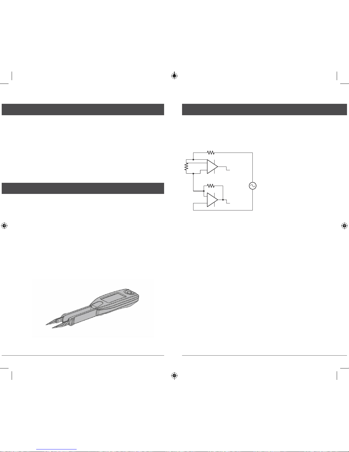
HOW IT WORkS
ST evaluates impedance of a compo
nent by measuring the voltag
e
across the comp
onent and c
urrent through it. The complex ratio
of
voltage to c
urrent is equal to the
complex impedance. The uni
t’s
proce
ssor
calculates various p
arameters that
are displayed i.e. R, C or L.
RS
may appear while using the device.
MENU STRUCTURE: Covers
menu structure, syste
m
settings and f
eatures.
OVERVI
EW
Smart Tweezers (ST) is a portable impedance measuring
device. ST is capable of measuring resistance, capacitanc
e
or inductance over a
range of more t
han 8 orders of
DUT
AU
RI
AL
VOLTAGE
SIGNAL
TO ADC
VS
CURRENT
SIGNAL
TO ADC
magnitude. The device has a basic
accuracy better
than
0.2% (resistance) and operates at four test frequencies.
Smart Tweezers is controlled by a microcontroller that sets
measurement conditions, processes data and op
erates the displa
y
and user
interface. The device has a unique mechanical design
that
allows manipulation SMT compo
nents with size down to
0201.
In
actual use
Smart Tweezers provides more accurate results than
most of the
benchtop LCR meters due to small and very predictabl
e
p
arasitics of its
probes. Probability of meas
urement errors
a
ssociated with setup
(wires, tips, probes and etc.) is minimal.
Voltage across the component is generated by
the test signal source
Vs. Both the amplitude and frequency of Vs can be set. The voltage
is
applied to the device under test
(DUT)
through the sourc
e
resistance
Rs. Current
flows to the virtual
ground of
the curren
t
amplifier
AI, and through the current conversion resistor Ri. The
output of AI
provides a
signal pr
oportional to the current, I*Ri.
Voltage across the
DUT is meas
ured by a separate signal
path
(amp
lifier
AU), thus
providing a
pseudo 4-wire Ke
lvin co
nnection.
Voltage and
current signals
are processed by
the A/D converter.
Obtained values are then corrected using calibration factors,
converted to impedance and sent to the display.
T
here are four selectable frequencies: 100
Hz, 120
Hz,
1.0kHz and 10kHz. The output frequency is accurate
to
50 ppm (0.005%). Frequencies are set in the menu or by
moving
the Navigation Controller to the RIGHT.
T
here are three output voltage levels that can
be
selected: 0.25 Vrms,
0.5 Vrms and 1.0 Vrms. The
accuracy of the out put voltage levels is 2 %.
3 4
SmartTweezers_Manual_03.8.indd 3-4 10/14/2011
2:04:08
PM
The
output voltage is applied to the device under
test
through the source impedance. The voltage across
the
device is always less
than or equal to
the
output
voltage. Source impedance values are
62.5Ω
(R1), 1kΩ
(R2)
and 16
kΩ (R3).
The source impedance is selected as a
function of the measurement
range. For most
devices, including resist
ors,
most
capacitors and many
inductors, the 1.0 Vrms setting provide best result.
For some inductor
s
and active devices, the 0.25 or 0.5 Vrms
setting should be used.
Certain devices require a specific test voltage, such
as
Z5U
ceramic capacitors (test voltage =
0.5 Vr
ms
for 25V
parts and 1.0V for < 16V parts).
Note: Use the largest voltage
possible for the best SNR and acc
uracy
.
The
ST5
provides three measurement
ranges (R1-R3). Each of
the
three ranges
has the source impedance of approximately
the
mid-scale impedance. The table below specifies
the
impedance ranges for each of the measurement
ranges.
Range
Source R dUT Impedance
1 62.5
Ω
< 400
Ω
2
1 k
Ω
400
Ω
< < 4 k
Ω
3
16 k
Ω
> 4 k
Ω
Note: Meas
urement
ranges determine an impedance
range (not
a value
range), so the ranges for inductance and capacitanc
e
depend upon the test frequency. In addition, the impedance
for capacitors is inversely pr
oportional to its
capacitance,
so
larger capacitors are measured in lower impedance
ranges.
During normal op
erations
the unit automatically changes to
the
optimal range for the
DUT. There is a
built-in hyst
eresis
allowing
to
avoid repeated range changes when a
component is near a range
boundary. The auto-ranging function can be disabled by user.
Range
holding is helpful if a number of
parts with similar values are
being measured or a
specific
measurement condition required.
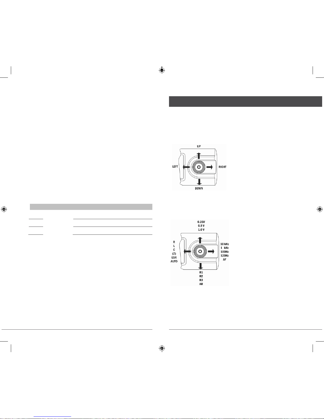
CONTROLS
The Navigation Controller
The controller is used to select a function or to
change
a
setting of Smart Tweezers. The controller can be moved
(rocked) in 4 directions (UP, DOWN, LEFT, RIGHT). Selection
is
performed by pressing along the vertical axis (PRESS).
Quick Controls
The Quick Controls allow changing test parameters or
modes
without entering the general menu by
moving the Navigati
on
Controller UP, DOWN, LEFT and RIGHT as shown below.
Note: To avoid
errors do
not use the Quick Controls
during compo
nen
t
measurement. The
Navigation Controller
response time
depends
on
the current test frequency.
The
following table summarizes functions of
the Navigation Controller moves:
UP
–
change test signal levels
DOWN
–
change test ranges
LEFT
– changemeasurementmodes
R
IGHT – change test freq
uencies
5 6
SmartTweezers_Manual_03.8.indd 5-6 10/14/2011
2:04:08
PM
POWER ON
POWER-ON - To turn the
Smart Tweezers O
N,
press the
Navigation Controller.
Note: Once
powered on, the unit will perfor
m
the last selected function.
POWER-OFF - ST
powers off automatically if neit
her
a
measurement is performed
nor the navigation controller i
s
operated for approximately 30 seconds (default value).
The power off timeout value can be set by c
hanging
the
TIMEOUT
setting in the SYSTEM m
enu.
The default power-off timeout is 30 seconds in
a
meas
urement
mode and 30 seconds in the MENU mode.
Note: Automatic power-off does not occur if test
freq
uency is manually set to 10kHz.
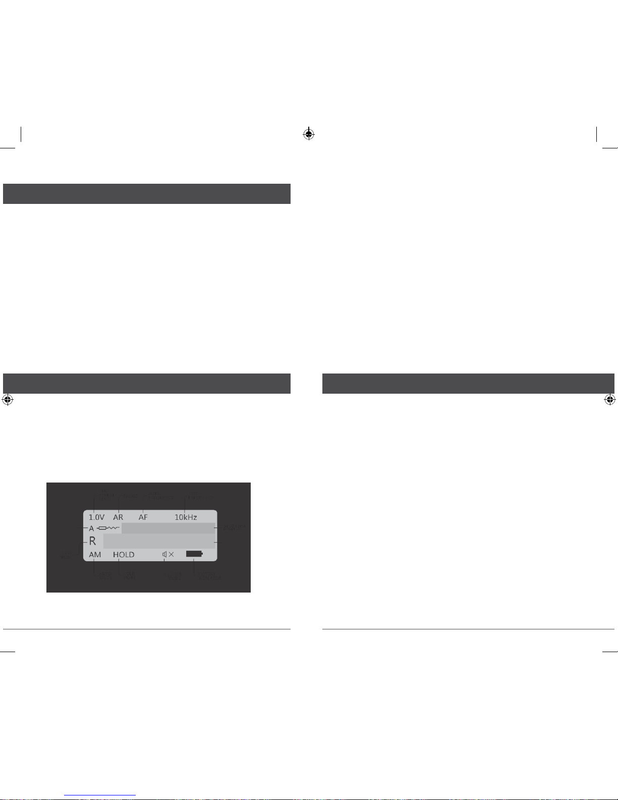
dISPL
AY
The sc
reen is
divided in four areas:
• Primary Display
• Secondary Display
• Test Parameters
• Device Status with Test Mode Indicator
PRIMARY DISPLAY: The Primary Display is
located in the middl
e
of the screen and uses the largest font. It
shows the dominan
t
impedance p
arameter reading typically with 5
digits displayed.
SECONDARY
DISPLAY: The Secondary Display is located just above the
Primary Display. It
shows the minor impedance parameter reading.
TEST
PARAMETERS: The Test Parameters
area is at the top of the
screen and provides information a
bout current test c
onditions
such as Test Frequency, Range, Test Signal level, Test Model.
DEVIC
E STATUS: The Device Status area is at the bottom of
the
screen and
provides information about the current Test Mode
and settings of the device: Hold, Audio and Battery Status.
TEST MOD
E INDICATOR: The Test Mode Indicator sign
is located immediately to the left of the Primary Display.
Symbols A, R, L, C, |Z|, ESR and Diode indicate Auto
,
Resista
nce, Inductance, Capacitance, Impedance
and ESR
measurement and Diode Test
mode respectively.
DISPLAYED PARAMETERS
The measurement
mode setting (R, L+R,
C+R, C+D, L+Q,
|Z|, ESR and AUTO) determines the measurement
type and the displayed
parameters
R MODE: Resistance is shown on the Primary The resistance
displayed is eit
her the equivalent series or parallel resistance
of the DUT. Resistance units
are mΩ,
Ω, kΩ, or
MΩ.
L+R MODE:
Inductance is shown on the Primary Display and the series
resistance on the
Secondary Display. The units of inductance
are µH,
mH or H. Resistance is the
real part of the impedance. Resistance units
are mΩ or
Ω. Serial equivalent
circuit is used in this
mode.
L+Q MODE: Inductance is shown on the Primary Display
and the quality factor Q on the
Secondary Display.
Inductance
units
are µH, mH or H. Q is the ratio of the imagi
nary part of
the
impedance to the real part of the impedance. Q is dimensionle
ss
and the same for both series and p
arallel representations.
A
g
ood inductance has a large L and a small R and thus a high Q..
7 8
 Loading...