

Page 1

ST-9116
Programming
Software
Manual
Rev V1.0 – MAR 2014
Page 2

SDRe Programming Software
Revision V1.0
P a g e | 2
Contents
1. Programming Software: .................................................................................................................. 6
1.1. Installation............................................................................................................................... 6
2. SDR programming software aspect and screen areas............................................................... 14
2.1.1. File name screen area: ................................................................................................. 15
2.1.2. Menu Bar screen area: ................................................................................................. 15
2.1.3. Quick Access Bar: .......................................................................................................... 16
2.1.4. Frequency Chart ........................................................................................................... 16
2.1.5. Scroll Control ................................................................................................................ 16
2.1.6. Information Bar ............................................................................................................ 16
2.1.7. Software Version .......................................................................................................... 17
2.2. Software configuration.......................................................................................................... 17
2.2.1. Repeater link to the computer: .................................................................................... 18
2.2.2. Software Language: ...................................................................................................... 19
3. File operations: ..................................................................................................................... 20
3.1. New program file creation: ................................................................................................... 20
3.2. Open an existing template or file .......................................................................................... 20
3.3. Saving the dashboard information to the currently opened file. ......................................... 21
3.4. Saving current dashboard into different file ......................................................................... 21
4. Repeater and parameters configuration ................................................................................... 22
4.1. Model selection..................................................................................................................... 22
4.2. Repeater Buttons Definition ................................................................................................. 24
4.2.1. Long Press Timer ............................................................................................................... 25
4.2.2. Buttons Actions: ................................................................................................................ 26
4.2.2.1. None .............................................................................................................................. 27
4.2.2.2. Channel Up .................................................................................................................... 27
4.2.2.3. Channel Down: .............................................................................................................. 27
4.2.2.4. Power Up: ...................................................................................................................... 28
4.2.2.5. Power Down .................................................................................................................. 28
4.2.2.6. Display Toggle ................................................................................................................ 28
4.2.2.7. Monitor ......................................................................................................................... 28
4.2.2.8. Monitor Momentary ..................................................................................................... 29
4.2.2.9. Status ............................................................................................................................. 29
Page 3

SDRe Programming Software
Revision V1.0
P a g e | 3
4.2.2.10. Menu ............................................................................................................................. 30
4.2.2.11. Reset .............................................................................................................................. 30
4.2.2.12. Slot Change ................................................................................................................... 30
4.2.2.13. Link Status ..................................................................................................................... 31
4.3. Enhanced optional programing ............................................................................................. 31
4.3.1. Repeater parameters ........................................................................................................ 32
4.3.1.1. Repeater name: ............................................................................................................. 33
4.3.1.2. Repeater ID: .................................................................................................................. 33
4.3.1.3. FAN Mode: .................................................................................................................... 34
4.3.1.4. Set Low Power on Voltage:............................................................................................ 34
4.3.1.5. Disable Repeater on Low Voltage: ................................................................................ 35
4.3.1.6. Power-on Test: ............................................................................................................... 35
4.3.1.7. Repeater Power Save mode: ......................................................................................... 36
4.3.2. Ethernet/IP configuration: ................................................................................................ 36
4.3.2.1. Default MAC Address: ................................................................................................... 37
4.3.2.2. Ethernet Speed: ............................................................................................................ 38
4.3.2.3. Ethernet MDI-X: ............................................................................................................ 39
4.3.2.4. IP Address setting: ......................................................................................................... 39
4.3.3. Roaming/Servers configuration: ....................................................................................... 40
4.3.3.1. User database Server: ................................................................................................... 41
4.3.3.2. Voice Server: ..................................................................................................................... 42
4.3.3.3. Monitor: ........................................................................................................................ 42
4.3.3.4. Mirror repeaters: ........................................................................................................... 42
4.3.4. SIP Server IP configuration: ............................................................................................... 43
4.3.5. Single Site trunking configuration: .................................................................................... 44
4.3.6. E-mail Service configuration: ............................................................................................ 45
4.3.6.1. Outgoing Services to the radios: ................................................................................... 45
4.3.6.2. Outgoing Services to the radios: ................................................................................... 46
4.4. Repeater and File Password Protection: ............................................................................... 46
4.4.1. Installer Password: ............................................................................................................ 47
4.4.2. DB Management Password: .............................................................................................. 48
4.5. CTCSS Table: .......................................................................................................................... 49
4.6. Profiles: ................................................................................................................................. 49
4.6.1. Analog Profiles: ................................................................................................................. 50
4.6.1.1. Adding a new Analog Profile ......................................................................................... 52
Page 4

SDRe Programming Software
Revision V1.0
P a g e | 4
4.6.1.2. Edit Analog Profile Name: ............................................................................................. 52
4.6.1.3. Selecting the type of audio filters ................................................................................. 53
4.6.1.4. CTCSS table enabled ...................................................................................................... 53
4.6.1.5. Enable the Voice Log Service on Analog Profiles .......................................................... 54
4.6.1.6. Enable the Roaming Service on Analog Profiles ........................................................... 54
4.6.1.7. Setup the repeater tail .................................................................................................. 55
4.6.1.8. Enable the Roaming Service on Analog Profiles ........................................................... 55
4.6.1.9. Repeater Penalty setup ................................................................................................. 55
4.6.1.10. Release time for time-out timer reset .......................................................................... 56
4.6.1.11. Voice inversion encryption setup .................................................................................. 56
4.6.2. Digital Profiles: .................................................................................................................. 57
4.6.2.1. Adding a new Digital Profile .......................................................................................... 59
4.6.2.2. Edit Digital Profile Name: .............................................................................................. 59
4.6.2.3. Selecting the type of Digital Modulation ...................................................................... 60
4.6.2.4. Crypto Key definition..................................................................................................... 60
4.6.2.5. Enable the Voice Log Service on Digital Profiles ........................................................... 61
4.6.2.6. Enable the Roaming Service on Digital Profiles ............................................................ 61
4.6.2.7. Hybrid Mode ................................................................................................................. 62
4.6.2.8. Setup the repeater tail .................................................................................................. 62
4.6.2.9. Enable the Call Length control on Digital Profiles ......................................................... 63
4.6.2.10. Repeater Penalty setup on Digital Profiles .................................................................... 63
4.6.2.11. Release time for time-out timer reset for Digital Profiles ............................................. 63
5. Adding a channel to a memory channel .............................................................................. 64
5.1. Updating the RX frequency of a channel: ........................................................................ 65
5.2. Updating the TX frequency of a channel ......................................................................... 65
5.3. Changing the RX sub audio signaling of a channel .......................................................... 65
5.4. Changing the TX sub audio signaling of a channel .......................................................... 66
5.5. Advanced channel configuration ..................................................................................... 66
5.5.1. Advanced configuration general tag ............................................................................ 66
5.5.1.1. Channel Tag ............................................................................................................... 66
5.5.1.2. RX frequency: ........................................................................................................... 67
5.5.1.3. RX sub Audio Signaling: ............................................................................................ 67
5.5.1.4. TX frequency: ............................................................................................................ 67
5.5.1.5. TX sub Audio Signaling: ............................................................................................ 68
5.5.1.6. Channel Power selection .......................................................................................... 68
Page 5

SDRe Programming Software
Revision V1.0
P a g e | 5
5.5.1.7. Squelch Sensitivity .................................................................................................... 69
5.5.1.8. Channel bandwidth .................................................................................................. 69
5.5.1.9. Channel mode selection ........................................................................................... 70
5.5.1.10. Channel Profile Selection: ........................................................................................ 70
6. Reading the Repeater programming from the device ......................................................... 71
7. Writing a radio file ................................................................................................................ 73
8. Repeater Alignment ............................................................................................................. 74
9. Repeater factory Reset ......................................................................................................... 74
10. Repeater Firmware Update: ............................................................................................. 76
11. Exit from Programming software ..................................................................................... 77
12. Manual software update .................................................................................................. 78
13. List of Figures .................................................................................................................... 80
Page 6

SDRe Programming Software
Revision V1.0
P a g e | 6
The SDR programmer software has been designed to be compatible with Microsoft Windows XP,
Windows 7 and Windows 8, in 32 or 64 bits version. If your operative system does not matches any of
these options, please contact us to mailto:techsupport@smartrunk.com
Note: 1 - SDR Programming Software Compatibility
1. Programming Software:
ST-9116 repeater has been equipped with USB 3.0 compatible port and
Ethernet 802.3 network port.
Programming software has been designed to let you control any of the
repeater features, looking for simplification of the programming process.
1.1. Installation
As you are a SmarTrunk distributor, the last updated programming
software is available on your shared server area (Drop Box). You also
can download it form our web site:
http://www.smartrunk.com/softwares/SDR/SDRe_Programmer_software.exe
Please run the installation software by double click on the file name:
This file is a self-extractor program, which will proceed to install SDRe
programming software for ST-91xx series of SmarTrunk Repeaters.
Page 7
SDRe Programming Software
Revision V1.0
P a g e | 7
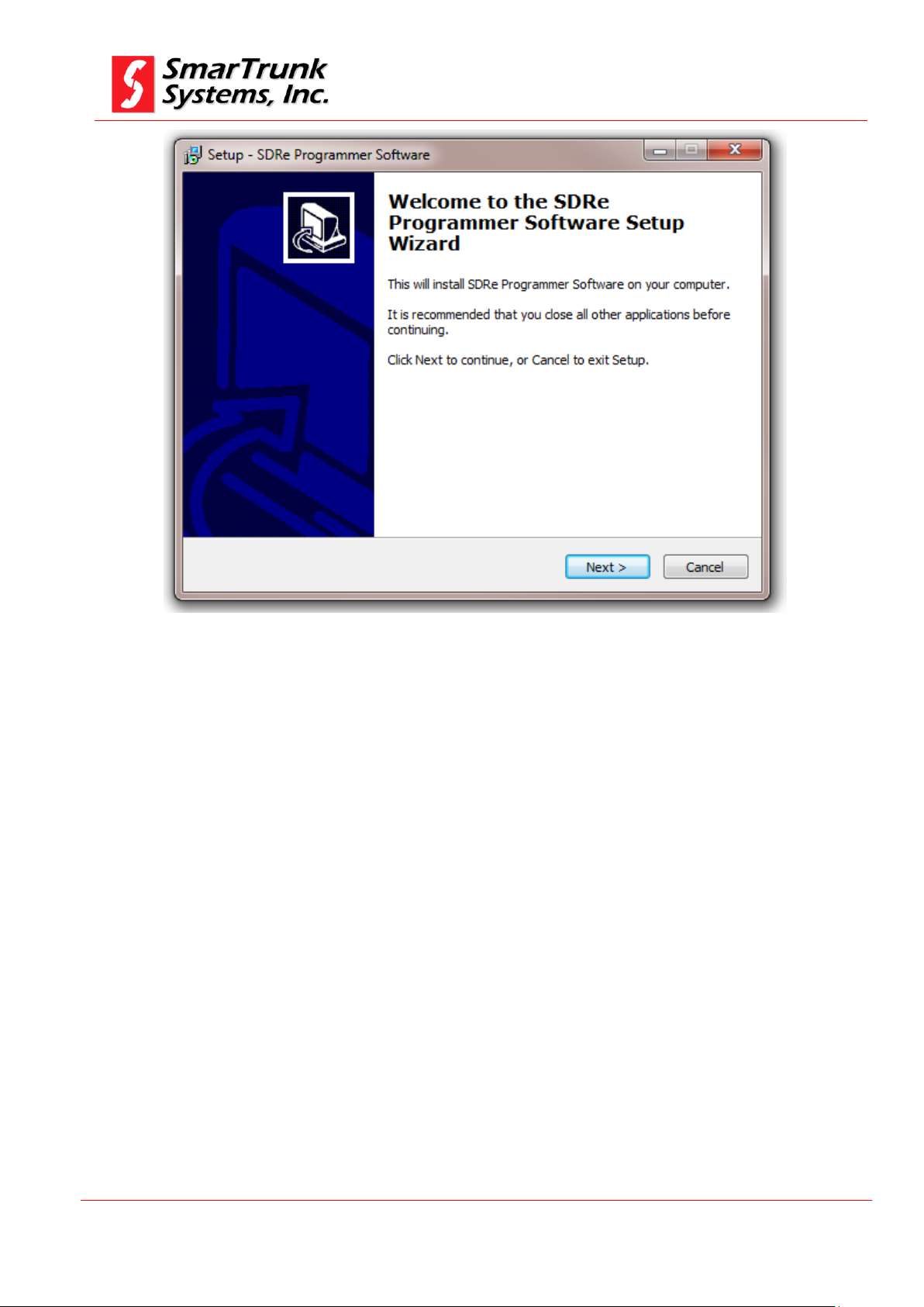
Figure 1: SDR programming software welcome screen
Click on [Next] to start the installation process.
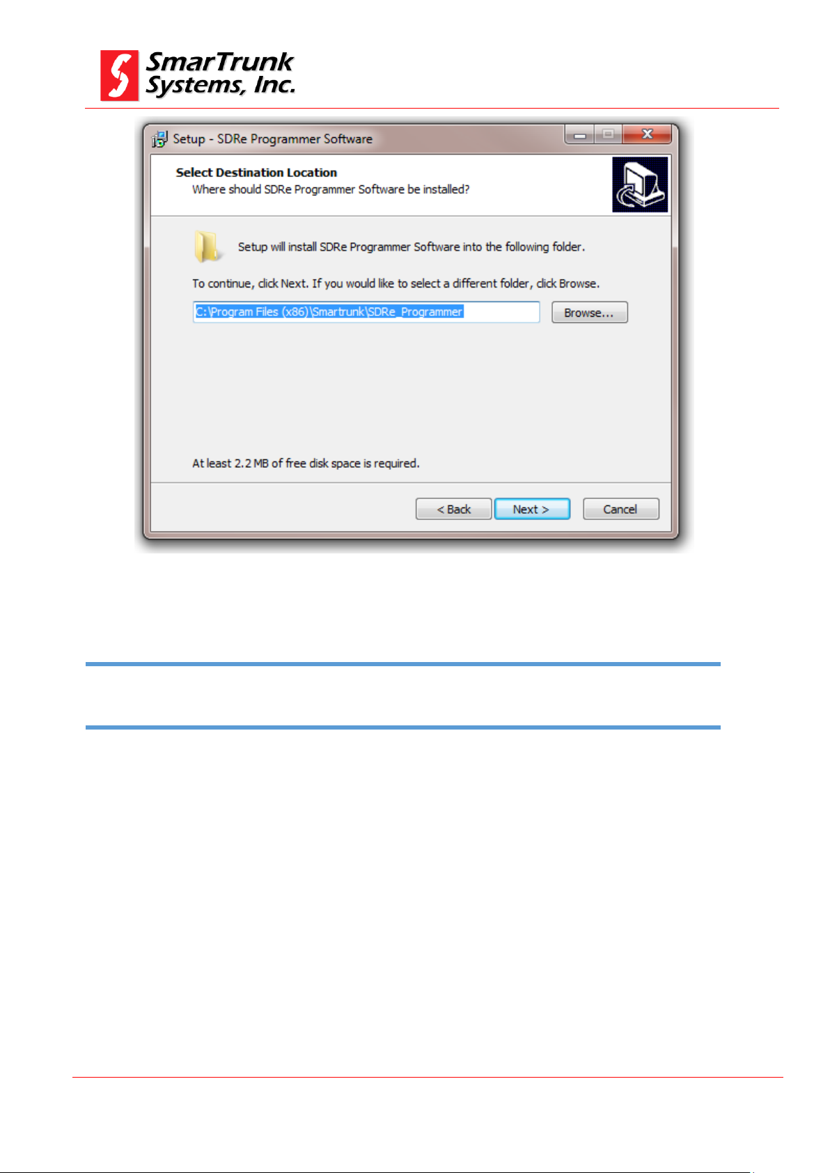
You will be prompted to introduce the destination folder. By default it is:
C:\Program Files (x86)\Smartrunk\SDRe_Programmer
However, you can change it as per your convenience.
Page 8
SDRe Programming Software
Revision V1.0
P a g e | 8
Please be sure that you have, at least, minimum free space in your destination disk as per the recommended on
this screen
Note: 2 Disk space requirement
Figure 2: SDR programming software file location setup
Click on [Next] to continue or [Back] to return to previous step.
Page 9
SDRe Programming Software
Revision V1.0
P a g e | 9
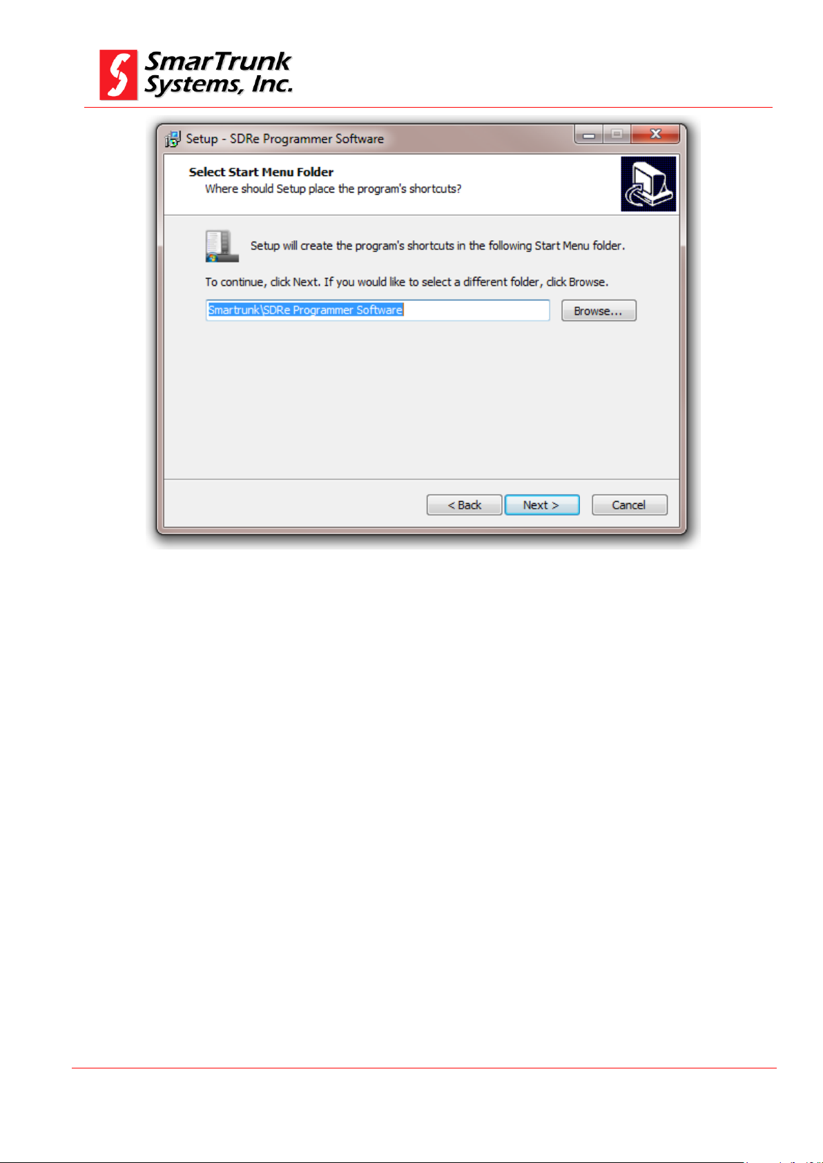
Figure 3: Start Menu destination
Please type the desired Menu folder where you will find the shortcut
to run the software once installed into your computer.
Default name is: SDRe Programmer Software
Click on [Next] to continue or [Back] to return to the previous step.
Page 10
SDRe Programming Software
Revision V1.0
P a g e | 10
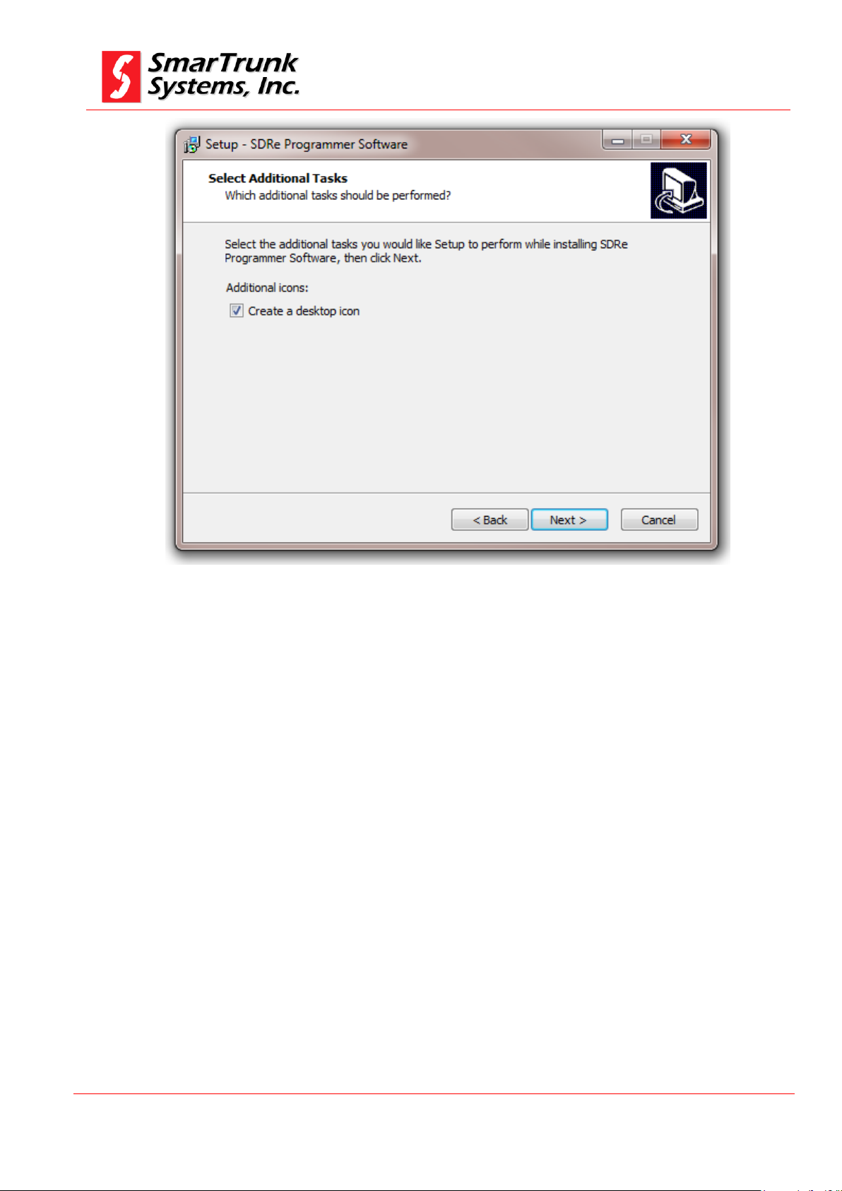
Figure 4: Additional task to be performed by installation software
If you do not want to create a shortcut into desktop, then uncheck the
mark.
Click on [Next] to continue or [Back] to return to the previous step.
Page 11
SDRe Programming Software
Revision V1.0
P a g e | 11
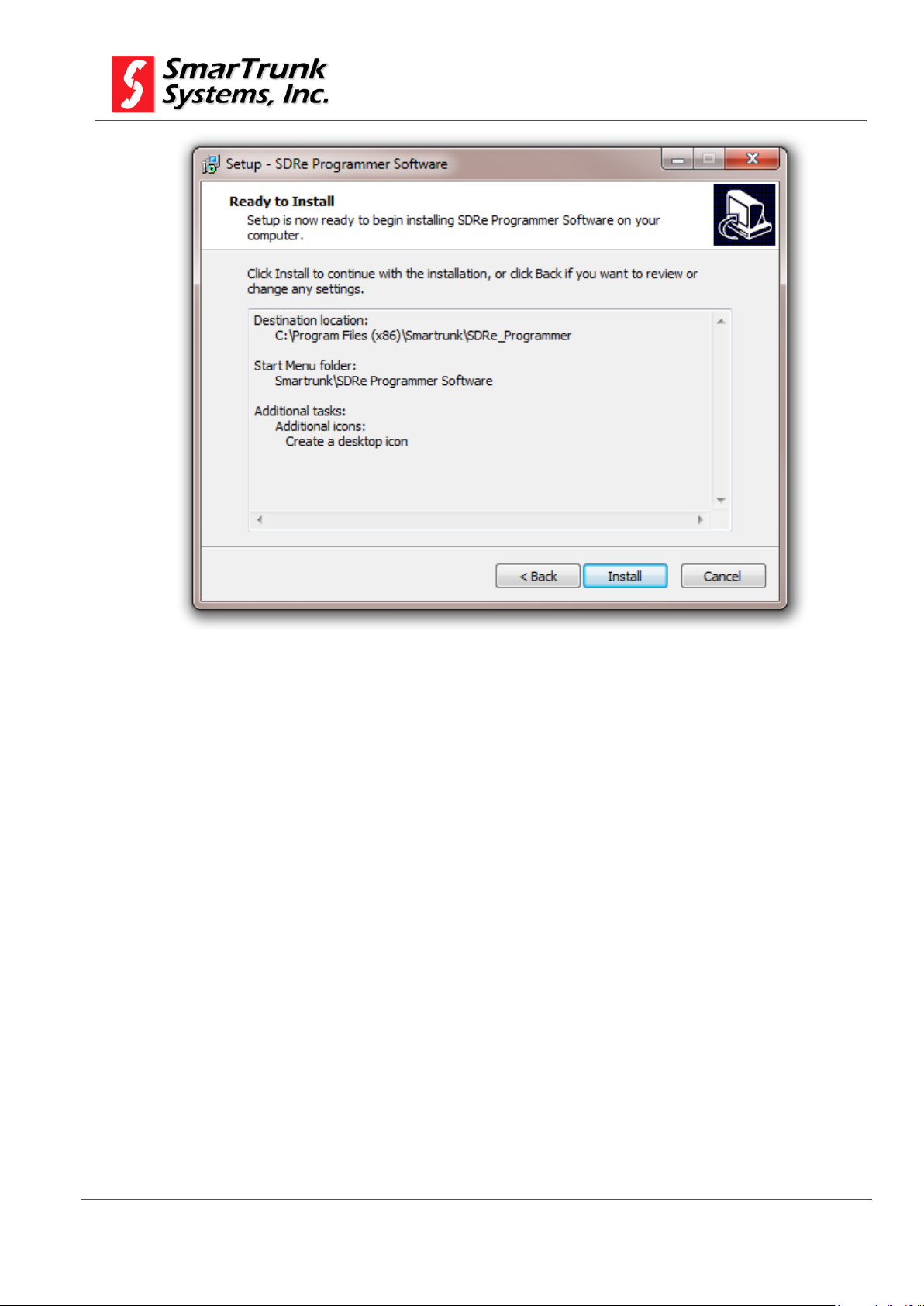
Figure 5: Installation parameters review
Check the option listed to ensure it is in agree to your desired setting,
then press [Install] to proceed with the installation or press [Back] to
return to the previous step
As soon as you press install, the progress bar shows you the
installation process evolution. It will take only few seconds to perform.
Page 12
SDRe Programming Software
Revision V1.0
P a g e | 12
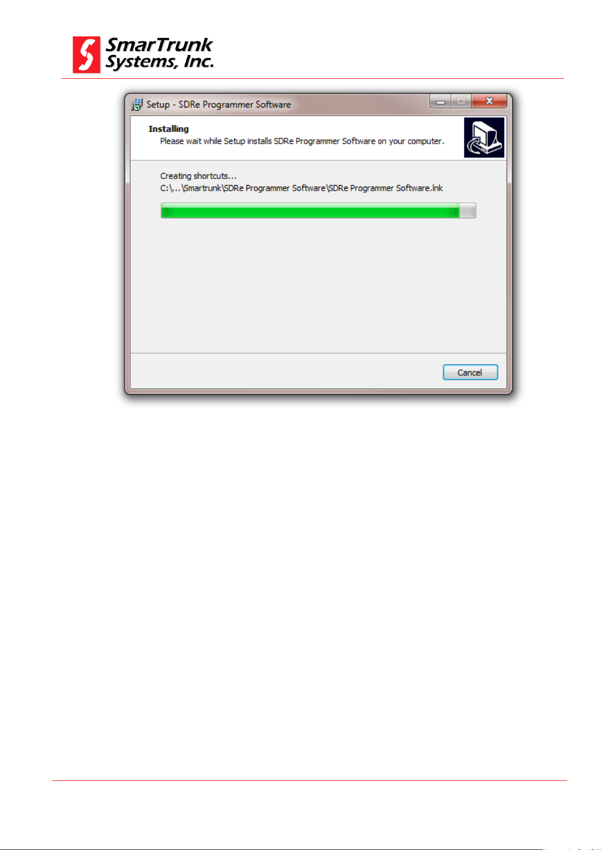
Figure 6: SDRe Programmer Software Installation progress bar
As soon as the installation finishes, you will be asked to run the
software or to finish the process.
Page 13
SDRe Programming Software
Revision V1.0
P a g e | 13
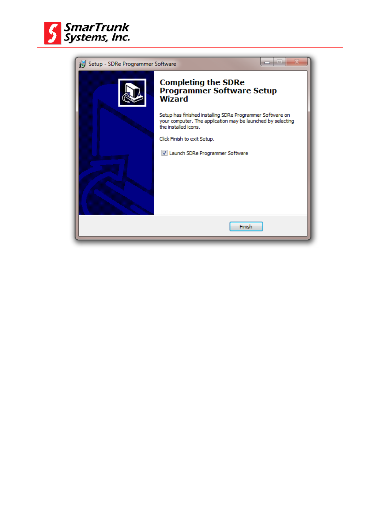
Figure 7: SDR Installation Software Final Screen
Leave the mark to run the software immediately or uncheck if you want
to run the software later.
If you leave the mark, then the SDR programming software starts
immediately.
Page 14
SDRe Programming Software
Revision V1.0
P a g e | 14
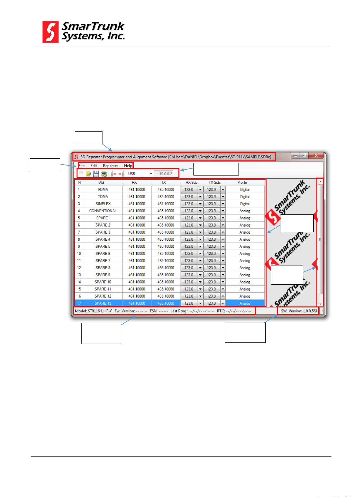
File name
Menu Bar
Quick Access Bar
Frequency
Chart
Scroll
control
Information
Bar
Sorftware
version
2. SDR programming software aspect and screen areas
For your convenience, the SDRe programming software has been
organized grouping the access to the different group of parameters or
actions into a very clear shape.
Page 15
SDRe Programming Software
Revision V1.0
P a g e | 15
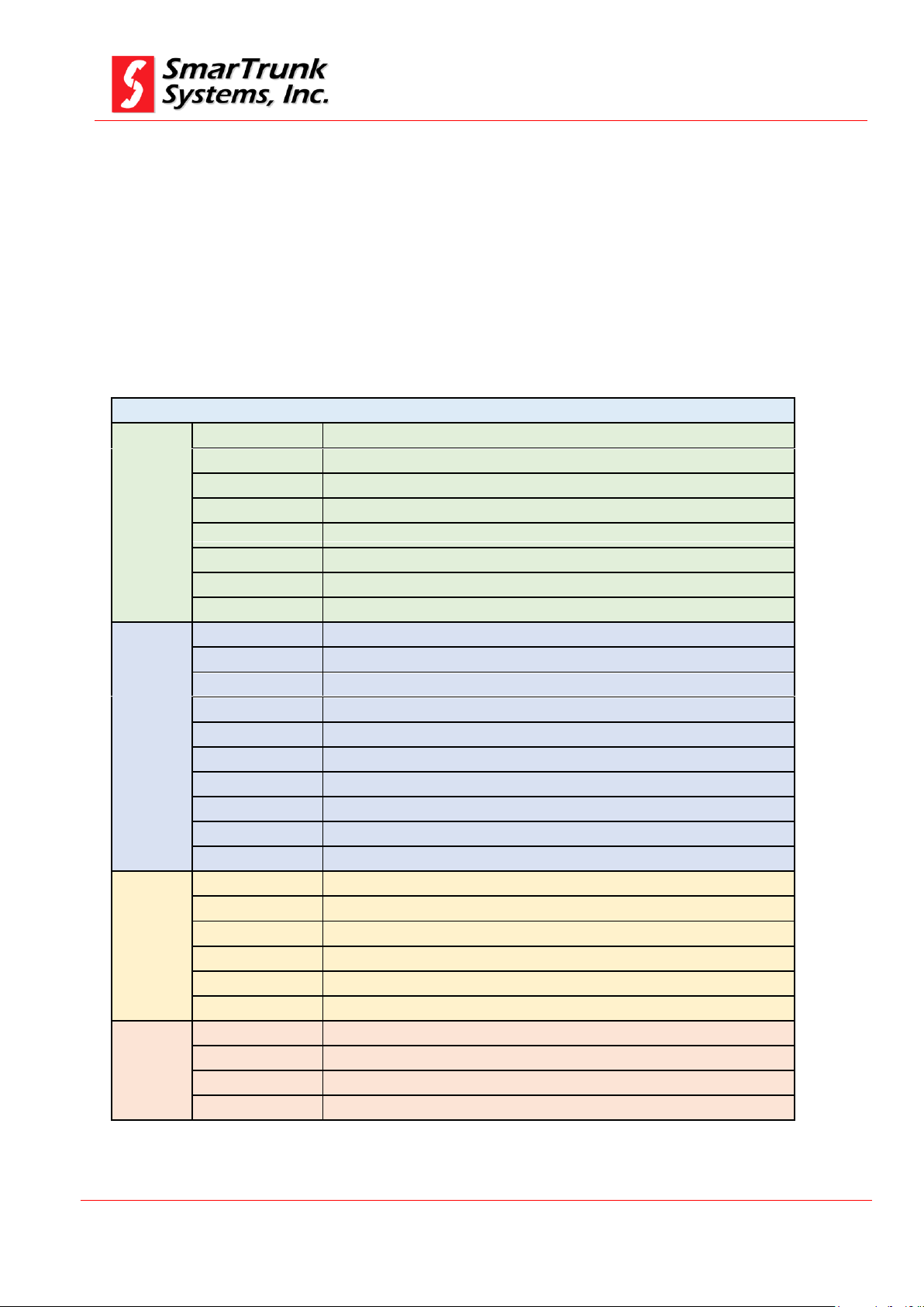
SDRE Programming software menu tree
File
New
Create a new file from scratch
Open
Open an existing file
Save
Save current programming information
Save As
Save current programming information on different file
Recent Files
Open a recently used file
Print
Print current programming information
Configuration
Software configuration screen
Exit
Close the SDR programming Software
Edit
Model Info
Radio Model information retrieved from radio memory
Buttons
Assign functionalities to radio buttons
Options
Choose the right options for networking and server control parameters
Passwords
Define password protection for current file
CTCSS Table
Access to radio phone book directory
Profiles
Analog, Digital, MDX, Xpress, SmarTrunk II, 5 Tones
MDC
Define the programing of MDC1200 signaling
Digital Profiles
Define digital profiles for the current file
Accessory port
Assign the function of each pin on the accessory connector
Advanced
Establish advanced features as voice files, sound files, display fonts and more
Repeater
Read Repeater
Read a connected radio
Write Repeater
Write the programming information to a connected radio
Restart
Factory Reset
Make a factory general reset
Alignment
Proceed with radio alignment
FW Update
Proceed to update radio firmware
Help
Index
Help index
Tech Support
Access to tech support e-mail or live chat
Software Updates
Look for software update
About
Related to the programming software release information
2.1.1. File name screen area:
This area shows the name and root to the current file in use. In case
you have not saved any file yet, this bar will shows only Programmer
and alignment Software.
2.1.2. Menu Bar screen area:
This screen area lets you get the access to the right menu of each one
of the features and services.
Table 1 Programming menu tree
Page 16
SDRe Programming Software
Revision V1.0
P a g e | 16
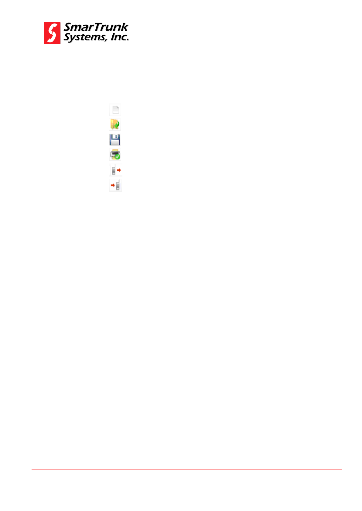
2.1.3. Quick Access Bar:
This tool bar includes the icons to be used a shortcut saving time for
most frequently actions:
Create a new file form scratch
Open an existing file
Save current file
Print current file information
Read the repeater
Write to the repeater
2.1.4. Frequency Chart
This is a sheet, which contains main information related to the
frequencies, signaling and labels assigned to the channels.
From this area, you will access to the detailed frequency programming
for each one of the repeater channels.
2.1.5. Scroll Control
In case of the quantity of channels programmed into a memory exceeds
the screen length, you can move the frequency chart by using this bar.
2.1.6. Information Bar
On this area, most important information related to current repeater
under programming, or to the previously downloaded file to one specific
repeater, is displayed.
Model info is related to the particular configuration of the repeater.
FW Version shows the firmware release currently downloaded into the
repeater.
Page 17
SDRe Programming Software
Revision V1.0
P a g e | 17
ESN shows the Electronic Serial Number of the attached device. It is
unique number who identifies the repeater.
Last Prog Shows the date and the time of the last time the attached
repeater has been programmed.
RTC Shows the current date and time of the Real Time Clock of the
attached repeater.
2.1.7. Software Version
This area displays the current software version you are using to
program SDR repeaters.
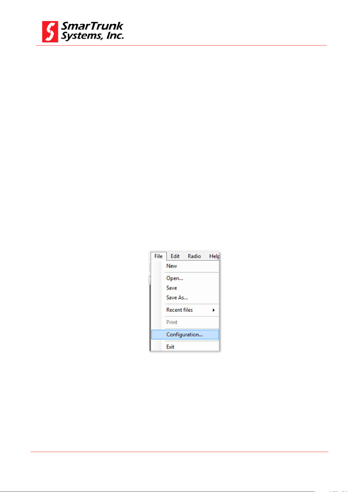
2.2. Software configuration
Before initial use, it is required to adjust the software as per your
environment.
Figure 9: SDR Programming Software Configuration Access
Page 18
SDRe Programming Software
Revision V1.0
P a g e | 18
As SDR repeater is not a standard device included into MW Windows library, you must install the
drivers before read or write a radio.
Note: 3 - Driver installation alert for USB Media Connection
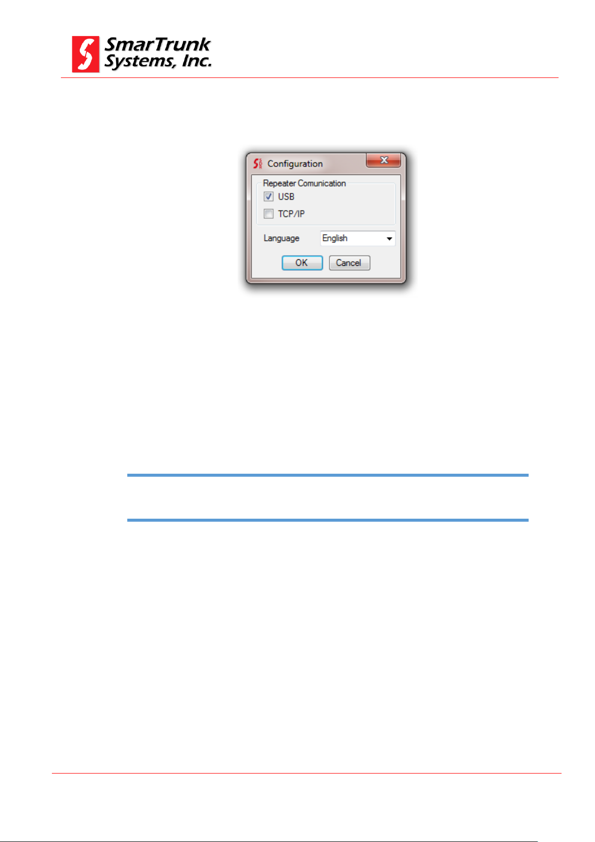
As soon as you click on [Configuration], the right configuration
screen pops up.
Figure 10: SDRe Programming Software Configuration Screen
2.2.1. Repeater link to the computer:
You can choose to connect your radios to the computer by USB
(default) or TCP/IP media protocol.
In case of USB media connection to the radio, it should be required
to install the drivers for your USB device.
As soon as you plug a SDR repeater to the computer through the
USB port, you will be prompted to install the driver. Installation
software already copy the files into the selected directory you have
introduced into the installation time, under {Drivers} folder: For
example:
C:\Program Files (x86)\SmarTrunk\SDRe_Programmer\Driver
Once you complete driver installation, the connection to the
repeater will be done automatically. The drivers must be installed
only once.
Page 19
SDRe Programming Software
Revision V1.0
P a g e | 19
Software update shall include new languages, so we recommend you try to keep your version
updated.
Note: 4 - Language Update Notice
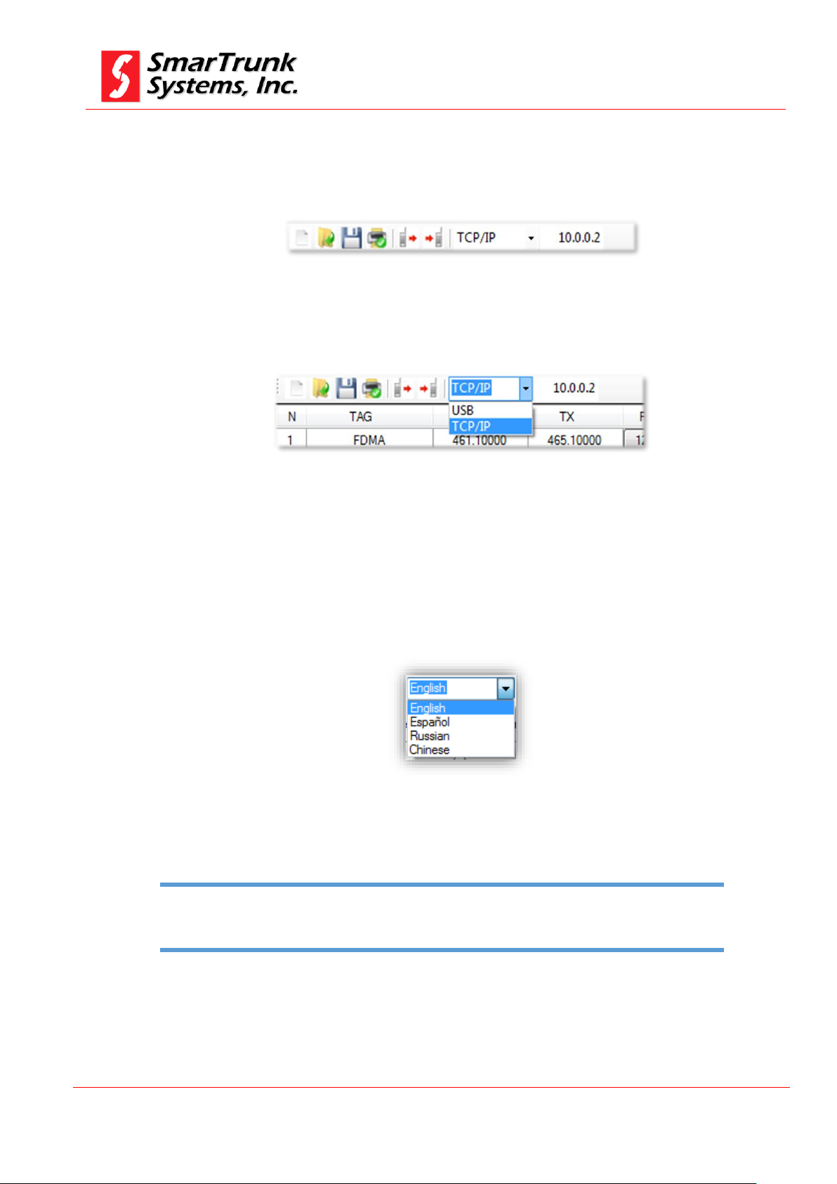
In case you prefer to program the repeater by Ethernet port, then
TCP/IP port must be checked and the right IP address of the
repeater to be programmed must be indicated into the quick access
bar:
Figure 11: Selecting IP address from the quick access bar
USB or TCP/IP selection may also be done form the bar:
Figure 12: Selecting communication media from the quick access bar
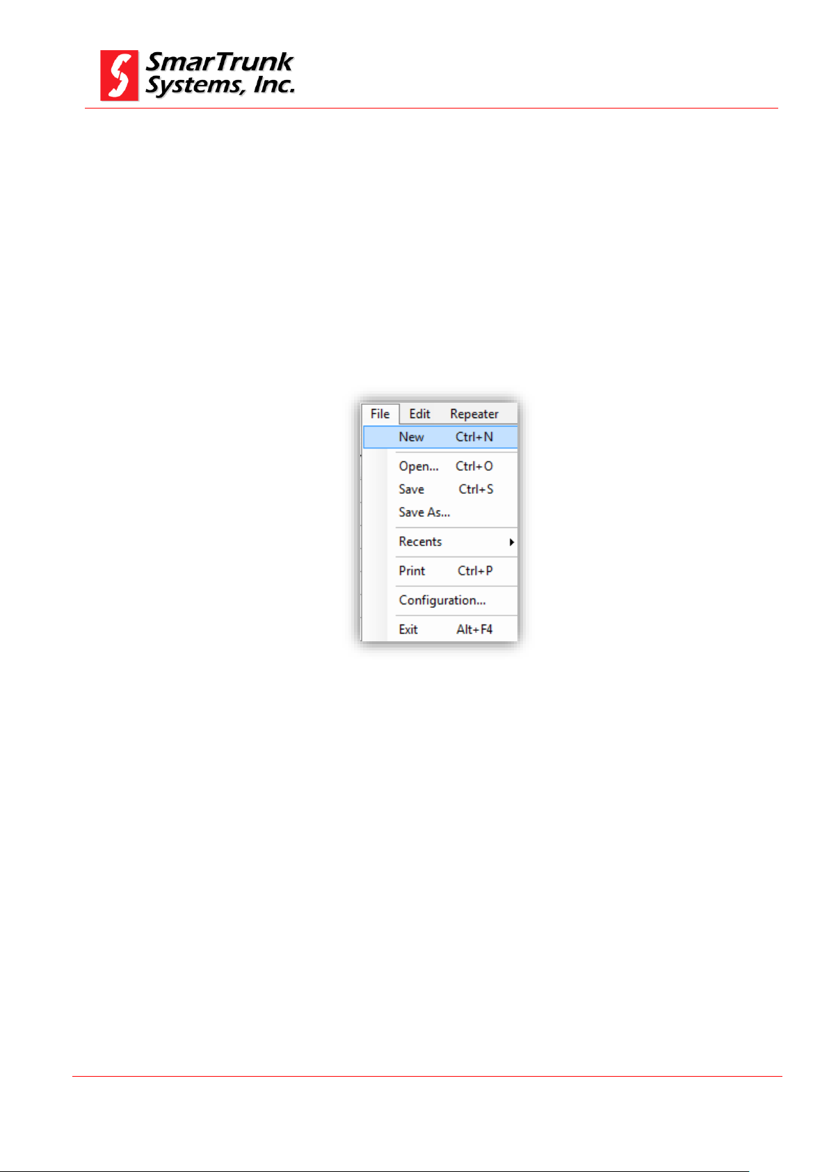
2.2.2. Software Language:
You can choose the language for your software interface.
Figure 13: Software Language Configuration Screen
Select your desired language interface by click on the desired
option.
Page 20
SDRe Programming Software
Revision V1.0
P a g e | 20
3. File operations:
3.1. New program file creation:
Evenly when in the future you can use existing files as templates
to define the programming file of a repeater, the first time you must
start from scratch, cleaning the dashboard.
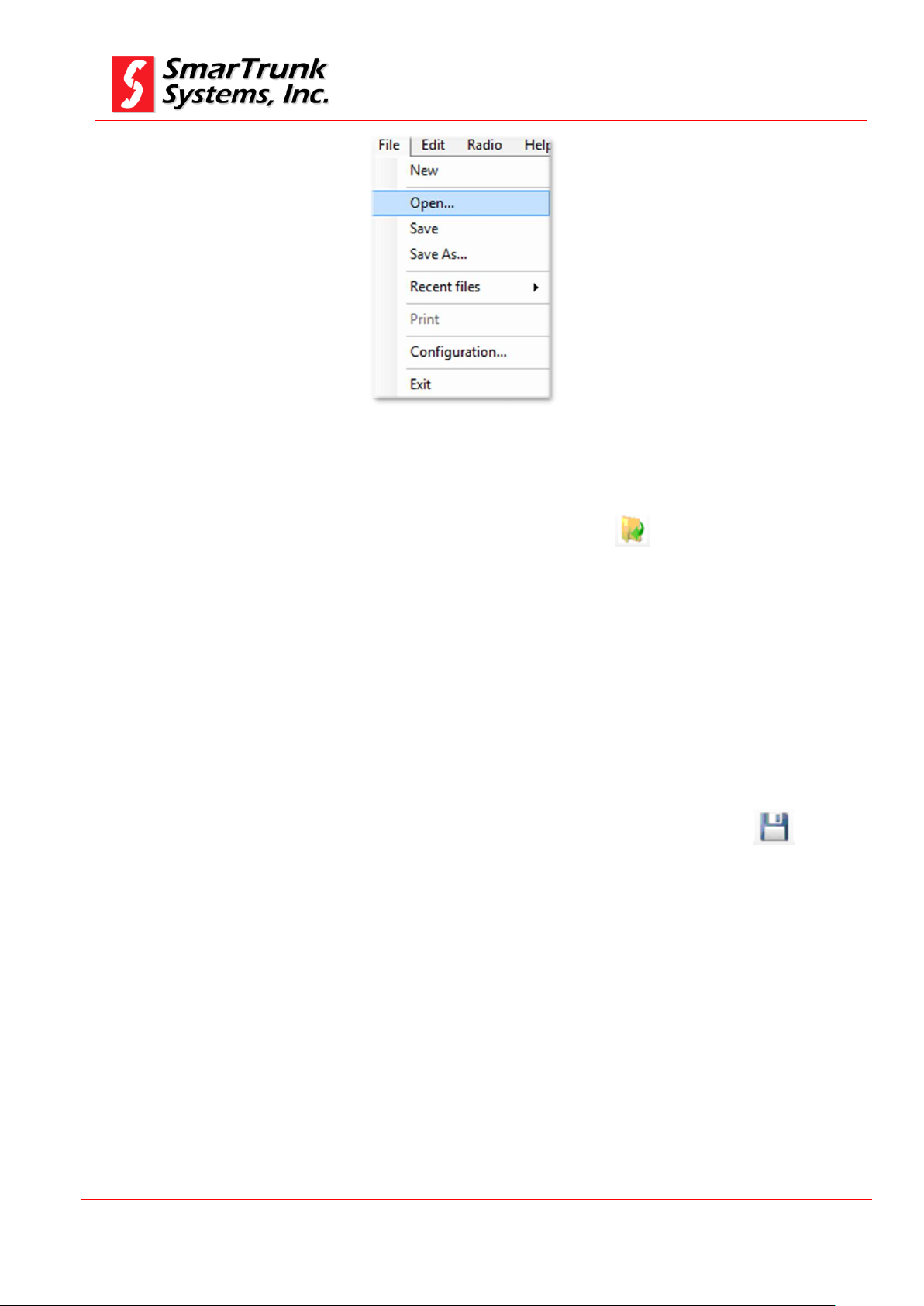
To create a new file you can use the quick access bar then click on
the new file shortcut or goes through [File] menu, and then select
[New]
Figure 14: New file access through File menu
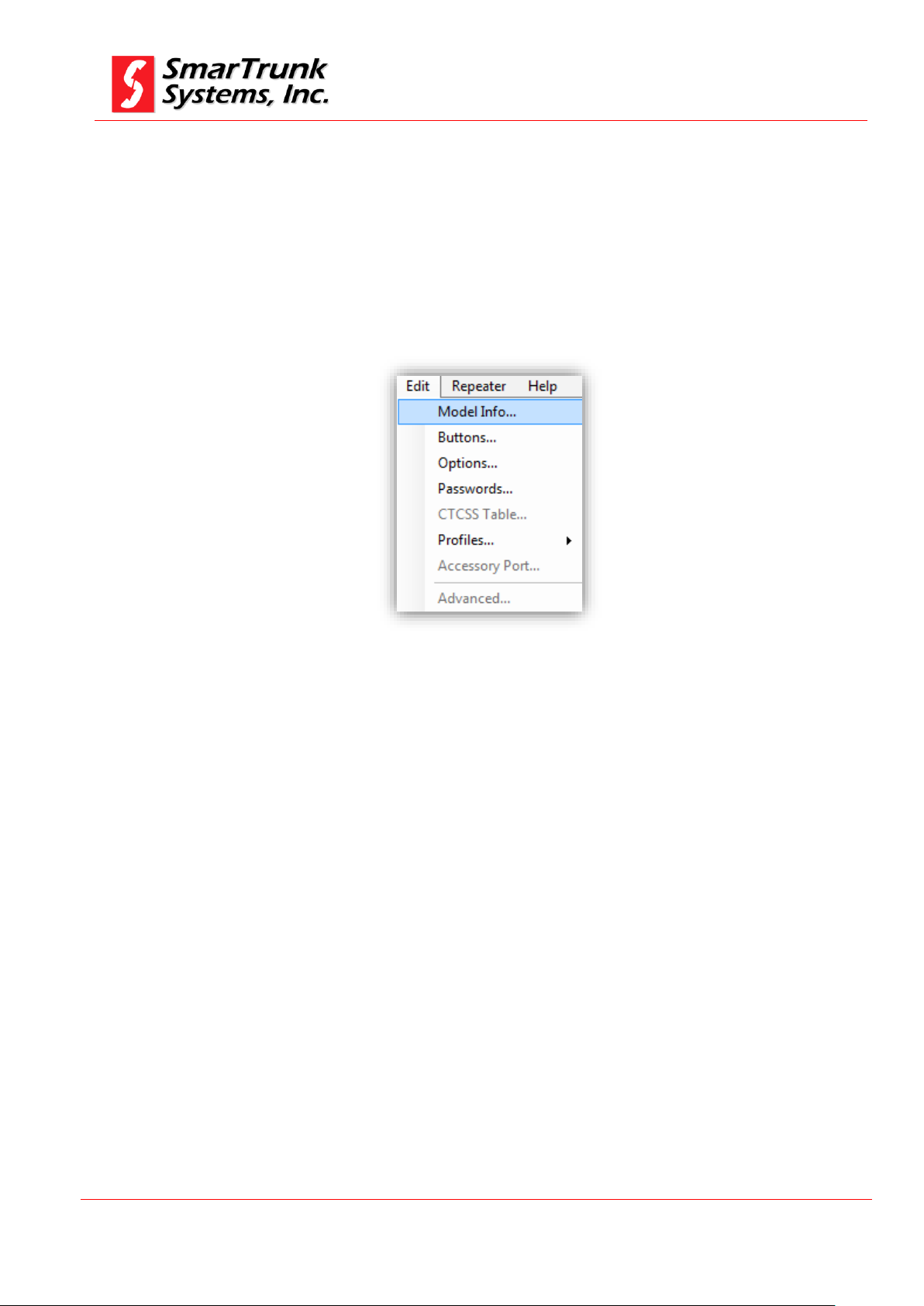
3.2. Open an existing template or file
To open an existing file or a template, please proceed to click on [File]
then [Open].
Page 21
SDRe Programming Software
Revision V1.0
P a g e | 21
Figure 15: Accessing to open an existing file or template
As soon as you clock on [Open] a windows Explorer screen will help you
to find the file.
You can also use the shortcut from the quick bar .
Once you found the file, click on [Open] to load the information into
your programming software dashboard.
3.3. Saving the dashboard information to the currently opened file.
To save current information on the programming software dashboard,
you can press [File] then [Save]. The currently opened file will be
updated.
Alternatively, you can also use the icon in the quick access bar:
3.4. Saving current dashboard into different file
To save current information on the programming software dashboard
but in different file, you can press [File] then [Save As].
A typical windows Explorer screen will prompt you to input the desired
file name and find the file location. Once selected it, the information will
be saved into the file.
In case the selected file name exists, the software will alert you to before
overwrite it.
Page 22
SDRe Programming Software
Revision V1.0
P a g e | 22
4. Repeater and parameters configuration
4.1. Model selection
Once a new file has been initiated, you must define the repeater
model to be programmed.
Figure 16: Model information access through Edit Menu
SDRe software can program any of the SmarTrunk Digital repeater
from ST-91XX family, but each repeater requires a proper definition
for most of the programming parameters.
Once you get access to the Model Info menu, a new screen will pop
up:
Page 23
SDRe Programming Software
Revision V1.0
P a g e | 23
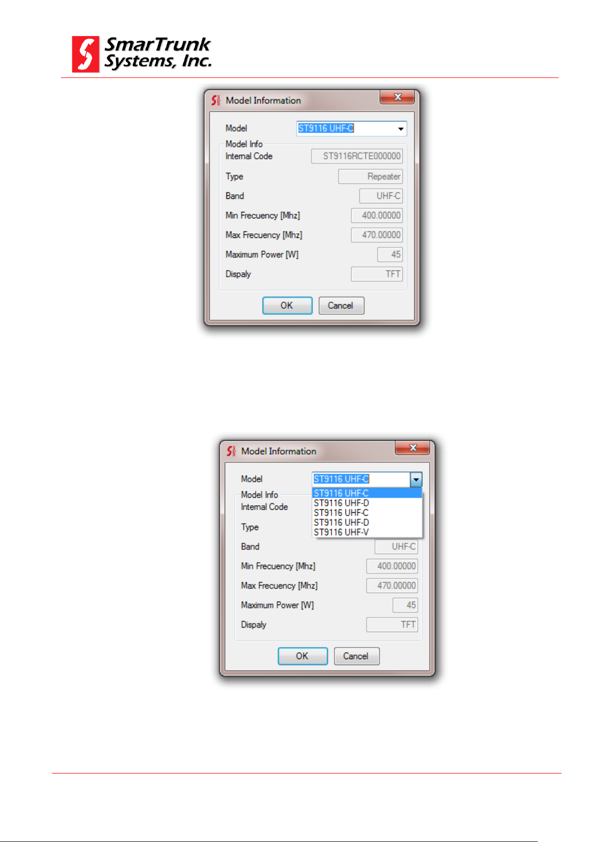
Figure 17: Model Info Screen
To select your desired model, click on the right corner of the model
field then a scrollable list will drop down.
Figure 18: Model info list
To select your model you must press over the right name
corresponding to your device.
Page 24

SDRe Programming Software
Revision V1.0
P a g e | 24
It is important to keep your software updated to ensure any SDRe repeater is into the model info list. If
your model is not into the current list, please update your repeater
Note: 5 - Incomplete model info list requires software update
If your repeater model is not in your list, please update your
software.
If you are not sure about your model info, you can read the repeater
by pressing the read button on the quick access bar once your
repeater is connected through the Ethernet port or USB cable with
the computer where the SDRe programming software is running.
Model info is also into the serial number label in the backside of
your repeater.
Once the model is selected, the correct frequency range, max power
and accessories are enabled into the model info screen.
Model: is the general model of the radio family.
Internal Code: is a production code assigned to the repeater into
the manufacturing process.
Radio Type: is the type of device.
Min Freq: Refer to the lowest operational frequency, which can be
programmed into your repeater.
Max Freq: Refer to the lowest operational frequency, which can be
programmed into your repeater.
Maximum Power: Is the maximum power supported by your RF
TX configuration. It may be different, depending on the region.
Display: Shows the type of display of the repeater
Once selected the right model press [OK] to accept it.
4.2. Repeater Buttons Definition
Before using the repeater, you must assign the functionality of each
one of the repeater buttons.
Please click on [Edit] then [Buttons] to access to the buttons
definition screen.
Page 25
SDRe Programming Software
Revision V1.0
P a g e | 25
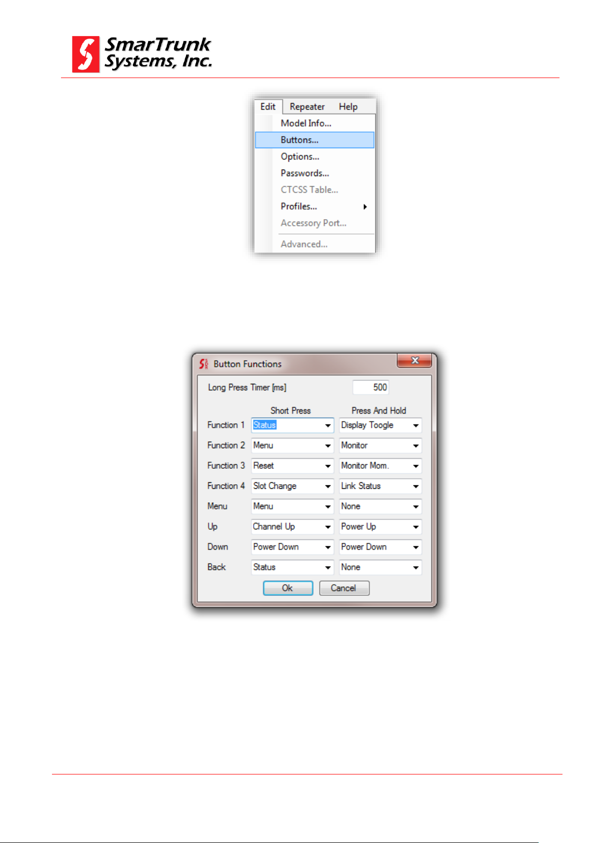
Figure 19: Accessing to Radio Buttons screen
As soon as you click on Buttons, a new screen will displayed.
4.2.1. Long Press Timer
Each button of your repeater has two functionalities to be assigned.
One is that function to be executed when the button is pressed and
Figure 20: Buttons Definition screen
Page 26

SDRe Programming Software
Revision V1.0
P a g e | 26
released immediately and the other is that function to be executed
when the button is pressed by long time.
Long Press timer is the minimum time in milliseconds [ms] that a
key must be held to be considered as Press and Hold action.
This parameter can be adjusted form 100msec up to 2500 msec.
Please define it as per your convenience.
4.2.2. Buttons Actions:
The Buttons Definition Screen lets you to assign different functions
to repeater buttons.
Click on the side arrow to open the selection list of possible functions
to be assigned to any of the buttons, and then click on the desired
function to be assigned.
To finish the function assignment, press [Ok] to return to the main
dashboard.
Press And Hold means a long push function assigned to such button.
Figure 21: Assigning the function to a button
Page 27

SDRe Programming Software
Revision V1.0
P a g e | 27
Depending on the application firmware loaded into your radio core,
some functions may not be allowed to be selected or defined.
Depending on the kind of button, some functionalities are not
allowed.
The actions to be assigned to the buttons are:
4.2.2.1. None
Use this option to disable the button.
4.2.2.2. Channel Up
Assign this command to move one-step up on the list of channels.
One Channel up means select the previous channel on the list of
channels defined on the main SDRe programming software
dashboard.
If the current selected channel selected is the top one on the list
of channels, then it will jump to the last channel on the list when
this action is executed.
In case only one channel is programmed on the current memory
bank, this action takes no effect.
4.2.2.3. Channel Down:
Assign this command to move one-step down on the list of
channels. One Channel down means select the next channel on
the list of channels defined for the current list on the main SDRe
programming software dashboard.
If the current selected channel is the last one on the list of
channels, then it will jump to the first channel on the list when
this action is executed.
In case only one channel is programmed on the current memory
bank, this action takes no effect.
Page 28

SDRe Programming Software
Revision V1.0
P a g e | 28
As this function does not care about any signaling, if you assign it to some button, then you
may know that the system privacy may be affected when this function is active
Note: 6 - Monitor privacy warning for a fleet
4.2.2.4. Power Up:
Assign this command to change the RF output power selection.
This command will jump from Low Power to Mid Power, from Mid
Power to High Power, from High Power to Low Power, depending
on the current power selection.
The absolute power assigned to each power selection must be
aligned as per Alignment section descripted on Service manual.
4.2.2.5. Power Down
Assign this command to scroll the RF output power selection.
This command will jump from High Power to Mid Power, from Mid
Power to Low Power, from Low Power to High Power, depending
on the current power selection.
The absolute power assigned to each power selection must be
aligned as per Alignment section descripted on Service manual.
4.2.2.6. Display Toggle
Commonly, the display backlight goes to power off mode after 10
seconds. If you want to let it continuously on by 12 hours, assign
this function to one button then you can toggle between power
save backlight mode and long term backlight on. This function is
useful for in-site maintenance or inspection.
4.2.2.7. Monitor
Assign this command to open the audio path without any
signaling or carrier level consideration.
This command only operates on analog and hybrid mode.
Page 29

SDRe Programming Software
Revision V1.0
P a g e | 29
It cannot be assigned to an instant action button. Only can be used as long press action
Note: 7 - Monitor Momentary allowed only to long press actions
4.2.2.8. Monitor Momentary
Assign this function when you want to open the audio path
without any signaling or carrier level consideration meantime the
assigned button is held.
This command only operates on analog and hybrid mode.
4.2.2.9. Status
Assign this command to show an instant status report on screen,
displaying the following information:
DC In: is the voltage on repeater DC input.
Temperature: Is the real temperature into the main board, very
close to the RF power module.
PWR Forward: It is a percentage of the power pushed by the
repeater in comparison to the calibrated value on the alignment
procedure. For example, if you align the repeater to transmit 30W
form the alignment software for such desired frequency, and now
the repeater is transmitting only 20W, you will see 66% on this
bar.
Page 30

SDRe Programming Software
Revision V1.0
P a g e | 30
Pwr. Forward and Antenna matching must be calibrated once the repeater has been installed
by aligning the RF power for the operation frequency, using the proper antenna, duplexer or
combiners. These values are a clear reference but it does not operate as a calibrated
instrument.
Note: 8 – Power and antenna matching calibration
On Once the main menu is accessed, navigation control keys function are overridden getting
the default navigation functions Home, Back, OK and Menu Exit
Note: 9 - Alternative navigation keys function under menu mode alert
ANT Match: This bar shows you the result of the comparison
between the SWR at calibration time related with actual SWR
status. 100% means the antenna remains working as at the
installation time.
4.2.2.10. Menu
Assign this command to let the user access to the general
repeater menu.
4.2.2.11. Reset
Assign this command to restart the repeater loading a set of new
desired parameters. Current call will be terminated and traffic
report and voice logger will be discarded.
4.2.2.12. Slot Change
Assign this command to change the time slot addressed to the
speaker for TDMA call monitoring.
Page 31

SDRe Programming Software
Revision V1.0
P a g e | 31
4.2.2.13. Link Status
Assign this command to check IP link status. The following screen
will shows you the complete status:
4.3. Enhanced optional programing
On this step, you can configure some networking parameters and
services features.
Figure 22: Option screen access through Edit Menu bar
As soon as you click on Options, the Optional programming features
screen will pops up.
Page 32

SDRe Programming Software
Revision V1.0
P a g e | 32
Figure 23: Options Program screen
To save the setting press [Ok] or [Cancel] to exit without saving the data
changes
4.3.1. Repeater parameters
This area lest you set some parameters:
Page 33

SDRe Programming Software
Revision V1.0
P a g e | 33
The ID must be unique into the entire system. Please be sure you are not defining the same ID for two
repeaters into the same network. Repeater ID is also used for Voting management.
Note: 10 – Unique ID advertence
Figure 24: Repeater Parameters tab
4.3.1.1. Repeater name:
This is an Alphanumeric Nickname assigned to the repeater to
get an easy access to this reference in the future, when you must
administrate a network.
4.3.1.2. Repeater ID:
This is a very important parameter in case you define a network
of repeaters into the system. This ID will help to identify each
repeater sharing the same IP address.
Page 34

SDRe Programming Software
Revision V1.0
P a g e | 34
4.3.1.3. FAN Mode:
The operating temperature of the repeater may not exceed 100°C
[212°F]. Depending on environmental conditions, the internal
FAN will help the heat-sync to keep temperature under the limit,
extending the repeater performance.
Press on the arrow to list down the possible values:
Figure 25: FAN Setting
Auto: The FAN will work controlled by repeater temperature
limits programed on the alignment procedure (See ST-9116
Service manual – Alignment).
On: The FAN will remains all time on. This option will demand
more quiescent current than required becoming inefficient. It
should be useful for high temperature environments.
Off: The FAN never will blow.
4.3.1.4. Set Low Power on Voltage:
If the DC power voltage drops under the limit programmed on this
field, then the repeater will jump to the low RF power programed for
the repeater to save battery. This feature is especially useful for
solar-powered sites or when the site works on power back up during
a possible AC failure.
Figure 26: Low power on low voltage setting
Page 35

SDRe Programming Software
Revision V1.0
P a g e | 35
Target value to Expected RSSI depends on each installation, so you can use a test channel
programmed into same TX than RX frequency and read the loop value on the main RX screen
once you hit the repeater. As this is a loop, you must reset the repeater once you get the RSSI
value
Note: 11 – RSSI loop value for Power-On Test
4.3.1.5. Disable Repeater on Low Voltage:
If the DC voltage is too low, then the repeater will be automatically
moved to stand-by mode serving only to emergencies.
Figure 27: Disable the repeater on low voltage
4.3.1.6. Power-on Test:
Check this box if you want the repeater transmit a test carrier
with some specific modulation when turned on as an additional
routine to the power-on test.
Figure 28: Power on test setting
Test Frequency is the frequency to be used to perform this test.
Expected RSSI is the loop value measured between TX and RX.
Value lower than expected means poor TX power. Higher values
means poor RX-TX isolation.
Page 36

SDRe Programming Software
Revision V1.0
P a g e | 36
4.3.1.7. Repeater Power Save mode:
In solar powered sites, it is very important to reduce the quiescent
current saving battery.
Click on the side arrow to select the proper power save mode:
Disabled: No power save functions
Normal: All internal resources are powered down, but the
receiver is all time powered on getting immediate reaction to any
call request.
Eco Mode: is an extreme power save, where all circuitry is
powered down, getting the receiver on only 100mSec by 300Msec
off. On this mode, the reaction may demand about 500msec to
recognize a call request, but the power saving efficiency is very
high.
4.3.2. Ethernet/IP configuration:
On this tab, you can program the parameters required for set the
repeater into an IP network environment.
Page 37

SDRe Programming Software
Revision V1.0
P a g e | 37
Figure 29: IP environment programming tab
4.3.2.1. Default MAC Address:
MAC address is a very important security parameter for any IP
network and additionally it may be used for external servers to
address a particular repeater into your network through the
routers.
Check this box to use the factory pre-assigned MAC address or
use your own if required, by typing it into the MAC field.
Figure 30: MAC address default setting
The MAC field is only active for typing if the Default MAC is not
selected.
Type 0123456789ab for MAC address 01:23:45:67:89:ab
Page 38

SDRe Programming Software
Revision V1.0
P a g e | 38
Figure 31: Sample of MAC Address input
4.3.2.2. Ethernet Speed:
Depending of the media quality and the possibilities of you link,
you can select the speed for the IP port.
Press on the side arrow to slide the menu down then select you
desired option:
Figure 32: IP port speed and mode selection
AUTO: The repeater will negotiate the most convenient
operational speed and mode in agree to the possibilities of your
network.
Evenly when this selection is convenient, the success of this
depends of the stability of your network because negotiation
takes some time. In case it must be negotiated very often, it will
be not convenient.
100Mbps Full: the PHY port will operate at 100 Mbps full duplex
(RX and TX at the time).
100Mbps Half: the PHY port will operate at 100 Mbps semi
duplex (never RX and TX at the same time).
10Mbps Full: the PHY port will operate at 10 Mbps full duplex
(RX and TX at the time).
10Mbps Half: the PHY port will operate at 10 Mbps semi duplex
(never RX and TX at the same time).
Page 39

SDRe Programming Software
Revision V1.0
P a g e | 39
4.3.2.3. Ethernet MDI-X:
Depending of the media type, the polarity of the wiring connection
must be normal or crossed. Press on the side arrow to select the
appropriate configuration for your network.
Figure 33: MDI-X selection
Auto: the PHY detects the type of connection adjusting the mode
on the fly
Normal: Check this one for normal IEEE 802.3 configuration
MDI-X: for crossed connections.
4.3.2.4. IP Address setting:
You have two ways to assign the IP address for the repeater.
DHCP: Check this box to leave an external DHCP server assigns
the most convenient IP address for your device.
Figure 34: Setting DHCP mode
Static: Check this box to define the IP address, mask, gateway
and DNS address manually.
Page 40

SDRe Programming Software
Revision V1.0
P a g e | 40
Figure 35: Manual configuration of the IP address
IP Address: Fill the IP address for your repeater, separated by
dots (IP V4 format).
MASK: Fill the MASK to define the sub net of your device.
Gateway: Fill the IP address (IP V4 format) for the gateway of your
network.
DNS Server: Fill the IP address for the DNS server of your
network.
4.3.3. Roaming/Servers configuration:
On this tab, you can program the parameters required for set the
repeater into a wide area IP network environment.
Page 41

SDRe Programming Software
Revision V1.0
P a g e | 41
Figure 36: Roamming/Servers definition screen
4.3.3.1. User database Server:
In a wide area network, the trunking/system database may be
located somewhere in the entire network. If this is the case, you
can check this box then fill the IP address assigned to the active
user database.
Figure 37: Selecting remote user database server
Page 42

SDRe Programming Software
Revision V1.0
P a g e | 42
4.3.3.2. Voice Server:
In a wide area network, the trunking/system voice resources
must be centralized into an external server.
This Server will assign the voice logger and the phone line
resources in agree to the right network configuration.
If you network has a voice server, please check this box and fill
the IP Address of you voice server.
Figure 38: Voice Server IP definition
4.3.3.3. Monitor:
In some system configuration, a centralized monitoring center is
defined. On this case, check this box then fill the address of the
monitoring device for your network
Figure 39: Addressing the monitor server
4.3.3.4. Mirror repeaters:
If your system is composed by single repeaters site, not trunked,
then you can broadcast the conversations in up to five different
locations.
Each mirror location must be integrated by a repeater or by a
console.
Fill the IP address for your mirrors separated by dots and check
the box in case the broadcast device is a repeater.
Page 43

SDRe Programming Software
Revision V1.0
P a g e | 43
Figure 40: Broadcast configuration for conventional repeater sites
4.3.4. SIP Server IP configuration:
On this tab, you can program the IP address of the SIP gateway. This
gateway will specify the codec, protocol and routing for any
communication exchanged with external switches.
Check the box if you want to enable/disable the SIP service.
To save changes press [Ok] or select other tab. If you want to cancel
the modifications for this tab, press [cancel].
Figure 41: SIP Server IP configuration tab
Page 44

SDRe Programming Software
Revision V1.0
P a g e | 44
Multi-site application software is another application. The programming of multi-site
trunking networks are outside of the scope of this manual
4.3.5. Single Site trunking configuration:
On this tab you can program the IP address and ports for any
repeater into the same site.
Figure 42: Single Site Trunking configuration
Fill the list with the IPs and ports for the repeaters into the same
site. All repeaters must be linked by IP media in order to synchronize
the entire site.
Check the box to enable single site trunking operation.
Page 45

SDRe Programming Software
Revision V1.0
P a g e | 45
To save changes, press [Ok] or select other tab. If you want to cancel
the modifications for this tab, press [cancel].
4.3.6. E-mail Service configuration:
On this tab, you can program the required parameters to support email services.
Figure 43: E-mail services configuration
4.3.6.1. Outgoing Services to the radios:
Incoming mails from the Internet must be received from the
repeater using POP3 service to connect to an e-mail server.
Fill the Server IP address, the port and the security mode as per
your POP3 service.
Page 46

SDRe Programming Software
Revision V1.0
P a g e | 46
Check Enable box to activate the service
Figure 44: POP3 Service configuration
4.3.6.2. Outgoing Services to the radios:
Outgoing e-mails coming from radios to the Internet must be
delivered from the repeater using SMTP service.
The SDR repeater has the SMPT Bridge embedded. You can
activate this service by filling the SMPT server IP address, port
and security mode, and then check the Enable box.
Figure 45: SMPT service configuration
4.4. Repeater and File Password Protection:
In most of the applications, it is important to protect programming
information.
To access to the password protection screen, please click on [Edit]
then click into [Passwords] tab.
Page 47

SDRe Programming Software
Revision V1.0
P a g e | 47
Figure 46: Access to Passwords programming screen
As soon as you click in [Passwords], the password programming
screen will be launched.
Figure 47: Installer and Data Base manager password protection screen
ST-91XX series offers two level of passwords protection: one for the
Technicians who install the repeaters, makes the alignment,
hardware programming, etc. and the second one for administrative
programmers, who only needs access to the repeater user database,
but no channel programming or alignment.
4.4.1. Installer Password:
This password enables the technicians to change the frequency
programming, align the entire repeater, and define the IP
environment parameters, Monitoring, Servers, etc., in local or
remote environment.
Page 48

SDRe Programming Software
Revision V1.0
P a g e | 48
In case both passwords be the same, at the time you login to the repeater, you can get
complete access to both areas.
To protect this repeater area, you must fill Installer Password field
and confirmation with key work of 6 numeric characters.
Figure 48: Installer password
Default Password in 123456. In you do not change it, the repeater
never asks for password understanding that it is not required.
Programming software send 123456 as default password to connect
remotely.
4.4.2. DB Management Password:
This password enables the system administrator to change users
database, including IDs, privileges, radios kill, radios alive, etc.
To protect this repeater area, you must fill DB Manager Password
field and confirmation with key work of 6 numeric characters.
Figure 49: DB Manager Password
Default Password in 123456. In you do not change it, the repeater
never asks for password understanding that it is not required.
Programming software send 123456 as default password to connect
remotely.
Page 49

SDRe Programming Software
Revision V1.0
P a g e | 49
4.5. CTCSS Table:
The SDR repeaters supports up to 32 private groups into analog or
hybrid mode. The signaling used to discriminate the groups is
CTCSS.
To enable a group, list the right CTCSS into the CTCSS table.
Figure 50: CTCSS Table
In case you do not fill any CTCSS table, the repeater operates only with
the defined CTCSS on the frequency chart.
4.6. Profiles:
From the main menu bar, press on [Edit] then [Profiles] to access to
profiles menu.
Page 50

SDRe Programming Software
Revision V1.0
P a g e | 50
Figure 51: Profiles Menu Access
Once you press on [Profiles], a list of possible profiles will be open. If
some profiles are on grey, it is because your firmware does not support
that service.
4.6.1. Analog Profiles:
All common characteristic of any analog profile common to any of
the channels in the repeater must be programed on this step and
the associated to the right frequencies on the chart later.
To access to the Analog profile menu, proceed pressing on [Menu]
then [Profiles], then [Analog]
Page 51

SDRe Programming Software
Revision V1.0
P a g e | 51
Figure 52: Accessing to the Analog Profile tab
Once you press on [Analog], the Analog Profile menu will be opened:
Figure 53: Analog Profile TAB
Page 52

SDRe Programming Software
Revision V1.0
P a g e | 52
4.6.1.1. Adding a new Analog Profile
To add a new Analog Profile, get focus on Analog Profiles list then
press Insert Key on your keyboard.
A new profile with default parameters will be created.
Figure 54: Default Analog Profile
4.6.1.2. Edit Analog Profile Name:
To edit the analog Profile name, focus your mouse pointer over
the Name filed on the Analog Profile TAB, then edit current name
as per your desires. Space character is invalid.
Figure 55: Changing the Analog Profile Name
Once you click on any other screen area, the new Profile Name is
updated.
Page 53

SDRe Programming Software
Revision V1.0
P a g e | 53
Press OK to save the changes.
4.6.1.3. Selecting the type of audio filters
Analog signals on SDR repeaters can be fltered on four modes. The
standard one is the de/pre-emphasized, but you also can select
other modes for some special application.
Press on the Audio Filters side arrow to slide down the menu.
Figure 56: Audio Filters selection for analog profiles
Flat: No filtering for RX or TX. The modulation audio is just the
discriminator signal (flat) from the receiver. This mode cannot be
used when the repeater integrates a network environment because
the audio exchanged to the IP or monitor should be emphasized.
De-Emphasis: Received signals are de-emphasized then modulated
in flat format.
Pre-Emphasized: Received signal is left flat and the TX modulation
on emphasized.
De/Pre-emphasized: Received signals are de-emphasized processed
on this condition then emphasized again for transmit. This mode is
the standard one.
To store this option, click on any part of the tab. To save the value,
press [Ok] or Cancel if you want to discard the changes.
If you want to use a pre-loaded CTCSS table, overriding any CTCSS
defined on the frequency chart, check this box.
4.6.1.4. CTCSS table enabled
Page 54

SDRe Programming Software
Revision V1.0
P a g e | 54
Figure 57: Enable CTCSS table on Analog Profile
To store this option, click on any part of the tab. To save the value,
press [Ok] or Cancel if you want to discard the changes.
4.6.1.5. Enable the Voice Log Service on Analog Profiles
ST-9116 repeater can log any voice conversation. If you want to
activate this service for a particular analog profile, please check this
box.
Voice is stored on the SD memory attached to the unit.
Old files are deleted automatically if the memory is full.
If no memory, the service is deactivated automatically.
Figure 58: Voice Log Enabled for Analog Profiles
To store this option, click on any part of the tab. To save the value,
press [Ok] or Cancel if you want to discard the changes.
4.6.1.6. Enable the Roaming Service on Analog Profiles
If you want to integrate a network, using this channel as a site of
your wide area coverage, then you must check this box. Once this
box is checked, audio from this repeater is processed and shared
through IP between any other site on the network.
Figure 59: Roaming Service Activation for Analog Profiles
Page 55

SDRe Programming Software
Revision V1.0
P a g e | 55
To store this option, click on any part of the tab. To save the value,
press [Ok] or Cancel if you want to discard the changes.
4.6.1.7. Setup the repeater tail
Fill this field with the length desired for repeater tail. 0 second means
no tail. Max value is 255 seconds.
Figure 60: Repeater tail setup
To store the value, click on any part of the tab. To save the value,
press [Ok] or Cancel if you want to discard the changes.
4.6.1.8. Enable the Roaming Service on Analog Profiles
If you want set a limit of minutes for a call length, then fill this field.
0 minute means no limit. Absolute Max call length is 255 minutes.
Figure 61: Repeater MAX Call Length
To store the value, click on any part of the tab. To save the value,
press [Ok] or Cancel if you want to discard the changes.
4.6.1.9. Repeater Penalty setup
If call length limit is reached, the repeater may apply a penalty for
the CTCSS tone (group) who has reached the limit.
For example, if a particular group, who uses one of the tones defined
on the CTCSS table, reaches the max length accepted for this profile,
that tone remains inactive by the amount of seconds defined on this
step.
Page 56

SDRe Programming Software
Revision V1.0
P a g e | 56
Max penalty length is 255 seconds.
0 seconds of penalty means no penalty, so the group can setup a
new call immediately.
Figure 62: Penalty for traffic control on Analog Profiles
To store the value, click on any part of the tab. To save the value,
press [Ok] or Cancel if you want to discard the changes.
4.6.1.10. Release time for time-out timer reset
If call length limit is active (Call Length timer not equal to 0), the
repeater may apply a penalty for the CTCSS tone who reached the
limit.
This parameter specifies the time without any activity of that group
to reset the time out timer, which controls the max call length.
To setup this value, please fill the field.
Figure 63: Release time for Traffic Control on Analog Profiles
Max Release time length is 255 seconds.
0 seconds of release means instant reset of the call length timer.
To store the value, click on any part of the tab. To save the value,
press [Ok] or Cancel if you want to discard the changes.
4.6.1.11. Voice inversion encryption setup
ST-9116 supports voice inversion encryption for analog profiles. If
you want to enable it, please check the [Enabled] box then input the
right voice inversion sub-carrier for this profile.
Page 57

SDRe Programming Software
Revision V1.0
P a g e | 57
Figure 64: Voice Inversion encryption configuration
To store the value, click on any part of the tab. To save the value,
press [Ok] or Cancel if you want to discard the changes.
4.6.2. Digital Profiles:
All common characteristic of any digital profile related to any of the
channels in the repeater, must be programed on this step, and then
associated to the right frequencies on the chart.
To access to the Digital profile menu, proceed pressing on [Menu]
then [Profiles], then [Digital]
Page 58

SDRe Programming Software
Revision V1.0
P a g e | 58
Figure 65: Accessing to the Analog Profile tab
Once you press on [Digital], the Digital Profile menu will be opened:
Figure 66: Digital Profile TAB
Page 59

SDRe Programming Software
Revision V1.0
P a g e | 59
4.6.2.1. Adding a new Digital Profile
To add a new Analog Profile, get focus on Digital Profiles area then
press Insert Key on your keyboard.
A new profile with default parameters will be created.
Figure 67: Default Digital Profile
4.6.2.2. Edit Digital Profile Name:
To edit the digital Profile name, focus your mouse pointer over
the Name filed on the Digital Profile TAB, then edit current name
as per your desire. Space character is invalid.
Figure 68: Changing the Digital Profile Name
Once you click on any other screen area, the new Profile Name is
updated.
Press OK to save the changes.
Page 60

SDRe Programming Software
Revision V1.0
P a g e | 60
4.6.2.3. Selecting the type of Digital Modulation
Digital Emissions on SDR repeaters can be used on three different
modes. FDMA (Frequency Domain Multiple Access), TDMA (Time
Domain Multiple Access) or Simplex mode (Transmit and receive on
the same frequency.
Press on the Digital Mode arrow to slide down the menu.
Figure 69: Digital Mode selection for Digital profile
FDMA: Transmits a single continuous 4FSK carrier @ 4800bps
using ultra narrow band (6.25 Khz Bandwidth)
TDMA: Transmits two slots over a continuous carrier of 9600 bps
using a narrowband channel (12.5Khz Bandwidth)
SIMPLEX: Similar to TDMA but the carrier is not continuous.
Repeater receives on slot 0 and transmits the same information on
slot 1, using the same frequency for TX and RX Simplex mode.
To store this option, click on any part of the tab. To save the value,
press [Ok] or [Cancel] if you want to discard the changes.
4.6.2.4. Crypto Key definition
SDR protocol improves a high security encryption for voice and data.
The encryption is encoded and decoded using a 128bits mask, which
must be defined on this tab.
Figure 70: Crypto Key for Digital Profile
Page 61

SDRe Programming Software
Revision V1.0
P a g e | 61
To simplify the key management, you must type any string up to 16
characters length. This key is case sensitive:
Figure 71: Sample of Crypto Key for digital profiles
To store this option, click on any part of the tab. To save the value,
press [Ok] or Cancel if you want to discard the changes.
4.6.2.5. Enable the Voice Log Service on Digital Profiles
ST-9116 repeater can log any voice conversation. If you want to
activate this service for a particular analog profile, please check this
box.
Voice is stored on the SD memory attached to the unit.
Old files are deleted automatically if the memory is full.
If no memory, the service is deactivated automatically.
Figure 72: Voice Log Enabled for Digital Profiles
To store this option, click on any part of the tab. To save the value,
press [Ok] or Cancel if you want to discard the changes.
4.6.2.6. Enable the Roaming Service on Digital Profiles
If you want to integrate a network, using this channel as a site of
your wide area coverage, then you must check this box. Once this
box is checked, audio form, this repeater is processed and shared
through IP between any other site on the network.
Page 62

SDRe Programming Software
Revision V1.0
P a g e | 62
Figure 73: Roaming Service Activation for Digital Profiles
To store this option, click on any part of the tab. To save the value,
press [Ok] or Cancel if you want to discard the changes.
4.6.2.7. Hybrid Mode
SDR protocol supports analog and digital modulations on the same
channel. Check this box if you want to allow the repeater to support
analog and digital radios over the same channel.
Figure 74: Hybrid mode activation
To store this option, click on any part of the tab. To save the value,
press [Ok] or Cancel if you want to discard the changes.
4.6.2.8. Setup the repeater tail
Fill this field with the desired repeater tail length. 0 second means
no tail. Max value is 255 seconds.
Figure 75: Repeater tail setup for Digital Profiles
To store the value, click on any part of the tab. To save the value,
press [Ok] or Cancel if you want to discard the changes.
Page 63

SDRe Programming Software
Revision V1.0
P a g e | 63
4.6.2.9. Enable the Call Length control on Digital Profiles
If you want Set a limit of minutes for a call length, then fill this field.
0 minute means no limit. Absolute Max call length is 255 minutes.
Figure 76: Repeater MAX Call Length on Digital Profiles
To store the value, click on any part of the tab. To save the value,
press [Ok] or Cancel if you want to discard the changes.
4.6.2.10. Repeater Penalty setup on Digital Profiles
If Call length limit is reached, the repeater may apply a penalty for
the digital ID who reached the limit.
For example, if a particular group, who uses the channel, reaches
the max length accepted for this profile, that group remains inactive
by the amount of seconds defined on this step.
Max penalty length is 255 seconds.
0 seconds of penalty means no penalty, so the group can setup a
new call immediately.
Figure 77: Penalty for traffic control on Analog Profiles
To store the value, click on any part of the tab. To save the value,
press [Ok] or Cancel if you want to discard the changes.
4.6.2.11. Release time for time-out timer reset for Digital Profiles
If Call length limit is active (Call Length timer not equal to 0), the
repeater may apply a penalty for the group who has reached the
limit.
Page 64

SDRe Programming Software
Revision V1.0
P a g e | 64
This parameter specify the time without any activity of that group to
reset the time out timer who controls the max call length.
To setup this value, please fill the field.
Figure 78: Release time for Traffic Control on Digital Profiles
Max Release time length is 255 seconds.
0 seconds of release means instant reset of the call length timer.
To store the value, click on any part of the tab. To save the value,
press [Ok] or Cancel if you want to discard the changes.
5. Adding a channel to a memory channel
To add a new channel to the repeater, please click on the first empty tag
name under the last channel tag into the list
Figure 79: adding a new channel tag
Type there the tag name to be assigned to the new channel, for example
TEST, then click on the RX frequency field for the new channel recently
created.
The programming software will complete the frequencies and signaling as
per default, so please overwrite it with you desired settings.
Page 65

SDRe Programming Software
Revision V1.0
P a g e | 65
5.1. Updating the RX frequency of a channel:
Just click with your mouse on it and type the new frequency value. If
the input is wrong, then the RX frequency field will be highlighted on
red.
5.2. Updating the TX frequency of a channel
Just click with your mouse on it and type the new frequency value. If
the input is wrong, then the TX frequency field will be highlighted on
red.
5.3. Changing the RX sub audio signaling of a channel
Just click on the side arrow of the desired value to adjust. A complete
list of options will be opened.
Figure 80: Selecting a new RX sub audible signaling
Click on the desired value to select it.
Page 66

SDRe Programming Software
Revision V1.0
P a g e | 66
5.4. Changing the TX sub audio signaling of a channel
Just proceed as in the previous item but in TX signaling column.
5.5. Advanced channel configuration
After the basic channel information has been loaded, you must double
click on the channel number to access to the advanced features
programming screen.
Figure 81: advanced channel configuration screen
5.5.1. Advanced configuration general tag
This tag shows mostly the same information than the main
dashboards.
5.5.1.1. Channel Tag
Shows the name of the channel. You can edit it just typing on the
field.
Page 67

SDRe Programming Software
Revision V1.0
P a g e | 67
Figure 82: Channel tag
Once selected the right parameter, press [Ok] to save it or
[Cancel] to exit.
5.5.1.2. RX frequency:
Shows the RX frequency for this channel. You can edit it by direct
typing over the field.
Figure 83: Channel RX information
Once selected the right parameter, press [Ok] to save it or [Cancel]
to exit.
5.5.1.3. RX sub Audio Signaling:
Shows the CTCSS or DCS information for the current channel.
Click on the side arrow then select a different one if you want to
change it.
Once selected the right parameter, press [Ok], press over to save
it or [Cancel] to exit.
5.5.1.4. TX frequency:
Shows the TX frequency for this channel. You can edit it by direct
typing over the field.
Page 68

SDRe Programming Software
Revision V1.0
P a g e | 68
Figure 84: Channel TX information
Once selected the right parameter, press [Ok] to save it or [Cancel]
to exit.
5.5.1.5. TX sub Audio Signaling:
Shows the CTCSS or DCS information for the current channel.
Click on the side arrow then select a different one if you want to
change it.
Once selected the right parameter, press [Ok] to save it or [Cancel]
to exit.
5.5.1.6. Channel Power selection
Shows the current power level assigned to the channel.
To change it, press on the side arrow then choose your desired
level.
Figure 85: Channel Power selection
Once selected the right parameter, press [Ok] to save it or [Cancel]
to exit.
Page 69

SDRe Programming Software
Revision V1.0
P a g e | 69
5.5.1.7. Squelch Sensitivity
Shows the current squelch level for current channel. It means the
absolute threshold level to consider if a carrier is present on the
receiver.
Press on the side arrow to select a new value from a drop down
list if you want to change it.
Figure 86: Squelch sensitivity
To select a value, scroll the list then click on the desired threshold
level.
Once selected the right parameter, press [Ok] to save it or [Cancel]
to exit.
5.5.1.8. Channel bandwidth
In analog mode, the channel bandwidth can be selected as per
used desire.
Figure 87: Channel Bandwidth Selection
Page 70

SDRe Programming Software
Revision V1.0
P a g e | 70
Press on the side arrow to change it if you want. Possible values:
12.5 KHz.
Once selected the right parameter, press [Ok] to save it or [Cancel]
to exit.
5.5.1.9. Channel mode selection
This option lets you assign existing signaling profile and
modulation type for the current channel.
Figure 88: Channel mode selection
Once selected the right parameter, press [Ok] to save it or [Cancel]
to exit.
5.5.1.10. Channel Profile Selection:
The right profile, previously defined on 4.6.1 or 4.6.2., must be
attached to the current channel by pressing the side arrow on
the Profile Field.
A list the pre-defined profiles will be listed.
Figure 89: type of modulation
Click over the right one to select it.
Once selected the right parameter, press [Ok] to save it or [Cancel]
to exit.
Page 71

SDRe Programming Software
Revision V1.0
P a g e | 71
When you download a Repeater file from the Repeater, previous information into your programming
software will be overwritten. Please ensure you have already saved that information before proceed to
download from the repeater
Note: 12- Downloading the repeater fill will overwrite existing information in Programming Software
6. Reading the Repeater programming from the device
All the information already downloaded to your radio can be retrieved
anytime.
In case that information has been protected by password, you must
know such critical information to start the reading process.
To read the radio file from the repeater, you must connect the radio to
the USB port on your computer or by IP, as previously defined on the
Programming Software configuration (see 2.2.1), then you can use the
shortcut in the quick access bar or you go through [Repeater] then
click on Read Repeater. F2 key on your computer keyboard can be used
as a shortcut also.
Figure 90: Accessing to read the repeater
Once you press on [Read Repeater], the information stored in the device
will be loaded to your programming software automatically.
As soon as the process starts, a progress bar will show you the process
evolution.
Page 72

SDRe Programming Software
Revision V1.0
P a g e | 72
It is very convenient to backup all sensitive information from a repeater into computer files so you can
immediately clone the repeater in any event.
Note: 13 - Save repeater information on computer files
Figure 91: Repeater read progress bar
As soon as the reading process ends, a confirmation screen will show
you the end of the reading process.
Figure 92: read repeater confirmation screen
After you got all the information, you can modify it the save or upload
again to the radio.
In case the model selected on the program file, according to 4.1, does
not matches the repeater that you are trying to read, the process cannot
progress and you must choose the right model before attempting again.
Figure 93: Model error reported when attempting to read a wrong repeater model
Page 73

SDRe Programming Software
Revision V1.0
P a g e | 73
7. Writing a radio file
Once you get a program into your programming software ready to
upload to a repeater, you must connect the device to the USB port on
your computer or remotely through a TCP/IP network, then you can
use the shortcut in the quick access bar or you go through
[Repeater] then click on [Write Repeater]. F3 key on your computer
keyboard can be used as a shortcut also.
Figure 94: Accessing to write the repeater
Once you press on [Write Repeater], the information stored in the
programming software will be uploaded to your repeater automatically.
As soon as the process starts, a progress bar will let you know the
process ongoing.
Figure 95: Writing to the repeater progress bar
As soon as the process ends, a pop up screen will notify the success
process.
Page 74

SDRe Programming Software
Revision V1.0
P a g e | 74
Attempting to upload to a radio will fail if the information generated with the programming software is
not for such radio model.
Note: 14- Model mismatch reports uploading error.
Figure 96: Repeater write confirmation screen
Repeater will do a power cycle to load the new parameters after a read
or write process.
8. Repeater Alignment
Refer to Service manual for alignment procedure.
9. Repeater factory Reset
In case the repeater has been realigned by somebody who does not
understand the procedure correctly or any other problem, which may
affect to the repeater performance, you can reset as per initial factory
settings.
This process will erase all the information on your repeater, which
cannot be recovered except from backup on computer files.
To proceed to reset the repeater as per factory default, please click on
[Repeater] then [Factory Reset]
Page 75

SDRe Programming Software
Revision V1.0
P a g e | 75
Figure 97: Accessing to restore factory default settings
As soon as you click on [Factory Reset], a warning message will alert
you about the process ready to go. If you are not sure, please press
[Cancel]. If you agree, please press [Yes] to continue.
Figure 98: warning message before restoring factory default
As soon as you press [Yes], the process starts. It demands only two
seconds, and then the confirmation message is displayed:
Figure 99: Factory default settings confirmation
Page 76

SDRe Programming Software
Revision V1.0
P a g e | 76
As soon as this process ends, the radio will do a power cycle to load the
new parameters.
10. Repeater Firmware Update:
Smartrunk will continue working into the new features and services
development for our repeaters so frequently you will find firmware
updates into our web site.
To download a new firmware to you repeater, once you have downloaded
it into your computer, please clock on [Repeater] then [FW Update]
Figure 100: Accessing to Repeater firmware update screen
A soon as you click on [FW Update] a new screen will pop up.
Figure 101: Repeater FW Update application screen
To find the new firmware to be downloaded to the repeater press to
proceed to open the Windows Explorer to look for the new file previously
downloaded to your computer.
Page 77

SDRe Programming Software
Revision V1.0
P a g e | 77
Uploading a wrong firmware to your repeater may cause a permanent damage to the circuitry.
Please verify several times that you are ready to upload a firmware version corresponding to
your radio model.
Note: 15 - Wrong model firmware upload warning
Surf in your computer to select the desired file then connect you
repeater to your computer USB port or through a TCP/IP network
connection and then press [Start] to initiate the firmware update
process.
A progress bar will show you the process progress.
As soon as it finishes, the repeater will do a power cycle automatically
to load the new firmware.
11. Exit from Programming software
To exit from the programming software please proceed through [File]
then [Exit]
Figure 102: Firmware update progress screen
Page 78

SDRe Programming Software
Revision V1.0
P a g e | 78
Before exit, verify if the current data has been saved. Any change will be lost.
Note: 16 - lost data on exit warning note
Figure 103: Exit from SDR programming software
12. Manual software update
You can check for new updates by clicking on [Help] then [Software
Update]
The software will look for the latest release in our web site. If your
software is up to date, then a confirmation screen will pop up.
Figure 104: Manually checking firmware update
Page 79

SDRe Programming Software
Revision V1.0
P a g e | 79
Figure 105: Software up to date confirmation screen
If no, the new software will be downloaded automatically.
Proceed to install the new software as descripted on 1.1
Page 80

SDRe Programming Software
Revision V1.0
P a g e | 80
13. List of Figures
Figure 1: SDR programming software welcome screen .......................................................................... 7
Figure 2: SDR programming software file location setup ....................................................................... 8
Figure 3: Start Menu destination ............................................................................................................ 9
Figure 4: Additional task to be performed by installation software ..................................................... 10
Figure 5: Installation parameters review .............................................................................................. 11
Figure 6: SDRe Programmer Software Installation progress bar ........................................................... 12
Figure 7: SDR Installation Software Final Screen .................................................................................. 13
Figure 8: Programming Software Main Screen Functional Areas ......................................................... 14
Figure 9: SDR Programming Software Configuration Access ............................................................... 17
Figure 10: SDRe Programming Software Configuration Screen ............................................................ 18
Figure 11: Selecting IP address from the quick access bar ................................................................... 19
Figure 12: Selecting communication media from the quick access bar ................................................ 19
Figure 13: Software Language Configuration Screen ............................................................................ 19
Figure 14: New file access through File menu ...................................................................................... 20
Figure 15: Accessing to open an existing file or template .................................................................... 21
Figure 16: Model information access through Edit Menu .................................................................... 22
Figure 17: Model Info Screen ................................................................................................................ 23
Figure 18: Model info list ...................................................................................................................... 23
Figure 19: Accessing to Radio Buttons screen ...................................................................................... 25
Figure 20: Buttons Definition screen .................................................................................................... 25
Figure 21: Assigning the function to a button ....................................................................................... 26
Figure 22: Option screen access through Edit Menu bar ...................................................................... 31
Figure 23: Options Program screen ....................................................................................................... 32
Figure 24: Repeater Parameters tab ..................................................................................................... 33
Figure 25: FAN Setting ........................................................................................................................... 34
Figure 26: Low power on low voltage setting ....................................................................................... 34
Figure 27: Disable the repeater on low voltage .................................................................................... 35
Figure 28: Power on test setting ........................................................................................................... 35
Figure 29: IP environment programming tab ........................................................................................ 37
Figure 30: MAC address default setting ................................................................................................ 37
Figure 31: Sample of MAC Address input ............................................................................................. 38
Figure 32: IP port speed and mode selection ....................................................................................... 38
Figure 33: MDI-X selection .................................................................................................................... 39
Figure 34: Setting DHCP mode .............................................................................................................. 39
Figure 35: Manual configuration of the IP address ............................................................................... 40
Figure 36: Roamming/Servers definition screen................................................................................... 41
Figure 37: Selecting remote user database server ................................................................................ 41
Figure 38: Voice Server IP definition ..................................................................................................... 42
Figure 39: Addressing the monitor server ............................................................................................ 42
Figure 40: Broadcast configuration for conventional repeater sites ..................................................... 43
Figure 41: SIP Server IP configuration tab ............................................................................................. 43
Figure 42: Single Site Trunking configuration ........................................................................................ 44
Figure 43: E-mail services configuration ............................................................................................... 45
Figure 44: POP3 Service configuration .................................................................................................. 46
Page 81

SDRe Programming Software
Revision V1.0
P a g e | 81
Figure 45: SMPT service configuration .................................................................................................. 46
Figure 46: Access to Passwords programming screen .......................................................................... 47
Figure 47: Installer and Data Base manager password protection screen ............................................ 47
Figure 48: Installer password ................................................................................................................ 48
Figure 49: DB Manager Password ......................................................................................................... 48
Figure 50: CTCSS Table .......................................................................................................................... 49
Figure 51: Profiles Menu Access ........................................................................................................... 50
Figure 52: Accessing to the Analog Profile tab ..................................................................................... 51
Figure 53: Analog Profile TAB ................................................................................................................ 51
Figure 54: Default Analog Profile .......................................................................................................... 52
Figure 55: Changing the Analog Profile Name ...................................................................................... 52
Figure 56: Audio Filters selection for analog profiles ............................................................................ 53
Figure 57: Enable CTCSS table on Analog Profile .................................................................................. 54
Figure 58: Voice Log Enabled for Analog Profiles .................................................................................. 54
Figure 59: Roaming Service Activation for Analog Profiles ................................................................... 54
Figure 60: Repeater tail setup ............................................................................................................... 55
Figure 61: Repeater MAX Call Length ................................................................................................... 55
Figure 62: Penalty for traffic control on Analog Profiles ....................................................................... 56
Figure 63: Release time for Traffic Control on Analog Profiles ............................................................. 56
Figure 64: Voice Inversion encryption configuration ............................................................................ 57
Figure 65: Accessing to the Analog Profile tab ..................................................................................... 58
Figure 66: Digital Profile TAB ................................................................................................................. 58
Figure 67: Default Digital Profile ........................................................................................................... 59
Figure 68: Changing the Digital Profile Name ....................................................................................... 59
Figure 69: Digital Mode selection for Digital profile ............................................................................. 60
Figure 70: Crypto Key for Digital Profile ................................................................................................ 60
Figure 71: Sample of Crypto Key for digital profiles .............................................................................. 61
Figure 72: Voice Log Enabled for Digital Profiles................................................................................... 61
Figure 73: Roaming Service Activation for Digital Profiles .................................................................... 62
Figure 74: Hybrid mode activation ........................................................................................................ 62
Figure 75: Repeater tail setup for Digital Profiles ................................................................................. 62
Figure 76: Repeater MAX Call Length on Digital Profiles ...................................................................... 63
Figure 77: Penalty for traffic control on Analog Profiles ....................................................................... 63
Figure 78: Release time for Traffic Control on Digital Profiles .............................................................. 64
Figure 79: adding a new channel tag .................................................................................................... 64
Figure 80: Selecting a new RX sub audible signaling............................................................................. 65
Figure 81: advanced channel configuration screen .............................................................................. 66
Figure 82: Channel tag .......................................................................................................................... 67
Figure 83: Channel RX information ....................................................................................................... 67
Figure 84: Channel TX information ....................................................................................................... 68
Figure 85: Channel Power selection ...................................................................................................... 68
Figure 86: Squelch sensitivity ................................................................................................................ 69
Figure 87: Channel Bandwidth Selection .............................................................................................. 69
Figure 88: Channel mode selection ....................................................................................................... 70
Figure 89: type of modulation .............................................................................................................. 70
Figure 90: Accessing to read the repeater ............................................................................................ 71
Figure 91: Repeater read progress bar .................................................................................................. 72
Page 82

SDRe Programming Software
Revision V1.0
P a g e | 82
Figure 92: read repeater confirmation screen ...................................................................................... 72
Figure 93: Model error reported when attempting to read a wrong repeater model ......................... 72
Figure 94: Accessing to write the repeater ........................................................................................... 73
Figure 95: Writing to the repeater progress bar ................................................................................... 73
Figure 96: Repeater write confirmation screen .................................................................................... 74
Figure 97: Accessing to restore factory default settings ....................................................................... 75
Figure 98: warning message before restoring factory default .............................................................. 75
Figure 99: Factory default settings confirmation .................................................................................. 75
Figure 100: Accessing to Repeater firmware update screen ................................................................ 76
Figure 101: Repeater FW Update application screen ........................................................................... 76
Figure 102: Firmware update progress screen...................................................................................... 77
Figure 103: Exit from SDR programming software ................................................................................ 78
Figure 104: Manually checking firmware update ................................................................................. 78
Figure 105: Software up to date confirmation screen .......................................................................... 79
Page 83

FCC Notices
FEDERAL COMMUNICATIONS COMMISSION INTERFERENCE STATEMENT
This equipment has been tested and found to comply with the limits for a Class B digital
device, pursuant to part 15 of the FCC Rules. These limits are designed to provide
reasonable protection against harmful interference in a residential installation. This
equipment generates, uses and can radiate radio frequency energy and, if not installed
and used in accordance with the instructions, may cause harmful interference to radio
communications. However, there is no guarantee that interference will not occur in a
particular installation. If this equipment does cause harmful interference to radio or
television reception, which can be determined by turning the equipment off and on, the
user is encouraged to try to correct the interference by one or more of the following
measures:
-Reorient or relocate the receiving antenna.
-Increase the separation between the equipment and receiver.
-Connect the equipment into an outlet on a circuit different from that to which the receiver
is connected.
-Consult the dealer or an experienced radio/ TV technician for help.
CAUTION:
Any changes or modifications not expressly approved by the grantee of this device could
void the user's authority to operate the equipment
Use only shielded cables to connect I/O device to this equipment. You are cautioned that
changes or modifications not expressly approved by the party responsible for compliance
could void your authority to operate the equipment.
RF exposure warning ·
This equipment must be installed and operated in accordance with provided instructions
and the antenna(s) used for this transmitter must be installed to provide a separation
distance of at least 105 cm from all persons and must not be co-located or operating in
conjunction with any other antenna or transmitter. End-users and installers must be
provide with antenna installation instructions and transmitter operating conditions for
satisfying RF exposure compliance.
 Loading...