

Page 1

ST-1000C (400Mhz ~ 470Mhz)
UHF FM COMPACT DIGITAL TRANSCEIVER
SERVICE MANUAL
SmarTrunk Systems, INC.
ST-1000C SM R1.1a
Page 2

ST-1000C SM R 1.0 SMARTRUNK SYSTEMS, INC.
2
Table of Contents
1. Specifications: ............................................................................................................................. 4
2. ST-1000 EXPLODED VIEW ............................................................................................................ 5
3. ST-1000 SIMPLIFIED DIAGRAM.................................................................................................... 6
4. - ST-1000 RF DESCRIPTION .............................................................................................................. 7
4.1. Circuit Configuration ............................................................................................................... 8
4.2. Receiver System ...................................................................................................................... 8
4.2.1. Front-end RF Receiver ......................................................................................................... 8
4.2.2. ANALOG Audio Processing .................................................................................................. 8
4.2.3. Virtual Squelch Circuit ......................................................................................................... 8
4.2.4. Virtual VOLUME CONTROL .................................................................................................. 9
4.2.5. Sub audio signaling .............................................................................................................. 9
4.2.6. ANALOG AUDIBLE SIGNALING ............................................................................................. 9
4.2.7. DIGITAL AUDIO PROCESSING............................................................................................... 9
4.3. Transmitter System ............................................................................................................... 10
4.3.1. ANALOG TX SIGNAL ........................................................................................................... 10
4.3.2. DIGITAL TX AUDIO: ............................................................................................................ 10
4.3.3. Driver and Final Amplifier Stages ...................................................................................... 10
4.3.4. Automatic Transmit Power Control ................................................................................... 11
5. RC-1000 ALIGNMENT ................................................................................................................ 12
5.1. Introduction .......................................................................................................................... 12
6. COMPLIMENTARY USER ALIGNMENT........................................................................................ 13
6.1. OPTION ALIGNMENT: ............................................................................................................ 13
6.1.1. SQUELCH LEVEL: ................................................................................................................ 13
6.1.2. ANNUNCIATION ................................................................................................................ 13
6.1.3. Tones ................................................................................................................................. 14
6.1.4. Voice activated transmission ............................................................................................. 14
6.1.4.1. VOX sensitivity level ...................................................................................................... 14
Page 3

ST-1000C SM R 1.0 SMARTRUNK SYSTEMS, INC.
3
6.1.4.2. VOX inhibit on receive ................................................................................................... 14
6.1.4.3. VOX delay ...................................................................................................................... 15
6.1.5. Battery save ...................................................................................................................... 15
6.1.6. Microphone sensitivity ...................................................................................................... 15
7. ST-1000 SCHEMATIC ................................................................................................................. 17
11 ST-1000 COMPONENT LOCATOR................................................................................................... 18
11.1 ST-1000 TOP LAYER COMPONENTS LOCATION ......................................................................... 18
11.2 ST-1000 BOTTOM LAYER COMPONENTS LOCATION ................................................................. 19
12 ST-1000 PCB LAYOUT .................................................................................................................... 20
12.1 ST-1000 TOP LAYER PCB LAYOUT .............................................................................................. 20
12.2 ST-1000 BOTTOM LAYER PCB LAYOUT ...................................................................................... 21
12.3 ST-1000 PCB GROUND LAYER .................................................................................................... 22
12.4 ST-1000 PCB POWER LAYER ...................................................................................................... 23
13 ST-1000 BOM ................................................................................................................................ 24
14 ST-1000C MECHANICAL BOM........................................................................................................ 30
15 ACCESSORY PORT: ......................................................................................................................... 32
16 ST-1000 SERVICE MANUAL REVISIONS .......................................................................................... 34
Page 4
ST-1000C SM R 1.0 SMARTRUNK SYSTEMS, INC.
4
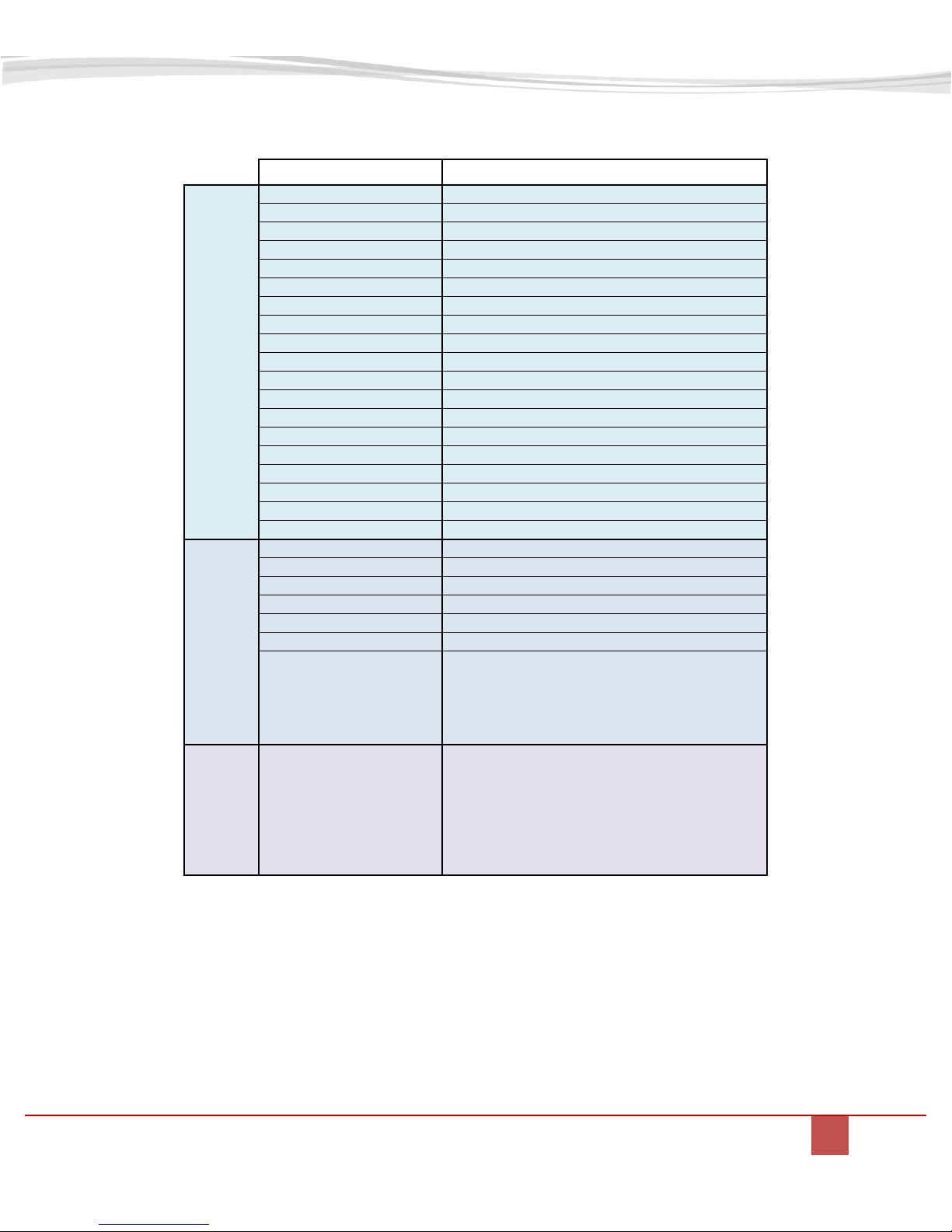
SPECIFICATION
ST-1000C
GENERAL
Frequency Range [Mhz]
400 TO 470
Channels
16
Power [Vdc]
6.4 to 8.8
Dimensions [mm]
120(H)x33(D)x57(W)
Weight [gr] (oz)
190 - (6.7)
Temperature range
- 30 °C ~ 60 °C (-22°F ~ +140°F)
Signaling
51 CTCSS tones / 183 DCS tones / 65533 SDR IDs
Display
No
Emergency call
No
GPS
No
Channel Scan
Yes
BCLO / BTLO
Yes
Power Saver control
Yes
TOT
Yes
Radio Kill/Alive
Yes
Adjustable Power Selection
H/L
Key lock
No
Password
Yes
Key Function selection
Yes
TRANSMIT
MAX RF power
2 W
Frequency Stability
>1PPM
Bandwidth [Khz]
12.5/25
Adjacent Channel Power
-65dBC (typ)
SNR
45dB typ
Analog harmonic distortion
5% typ (AF 1Khz, 60% deviation)
Data transmit rate
2400/4800bps
Max frequency deviation
2.5Khz@12.5Khz BW/5Khz@25Khz BW
Analog Modulation type
11K0F3E, 25K0F3E
FDMA Digital emissions
8K30F1E, 8K30F1D, 8K30F1W
Ext. Mic. Impedance
600 Ohms
RECEIVER
Analog Sensitivity
0.25uV (12dB Sinad)
Digital Sensitivity
0.3uV (5% BER)
Image rejection
60dB typ
Adjacent Channel selectivity
60dB typ @25KHz BW
HUM and NOISE ratio
40dB
Speaker Audio Power
1W
External audio power
1W
1. Specifications:
Specifications subject to change without notice or obligation
Page 5
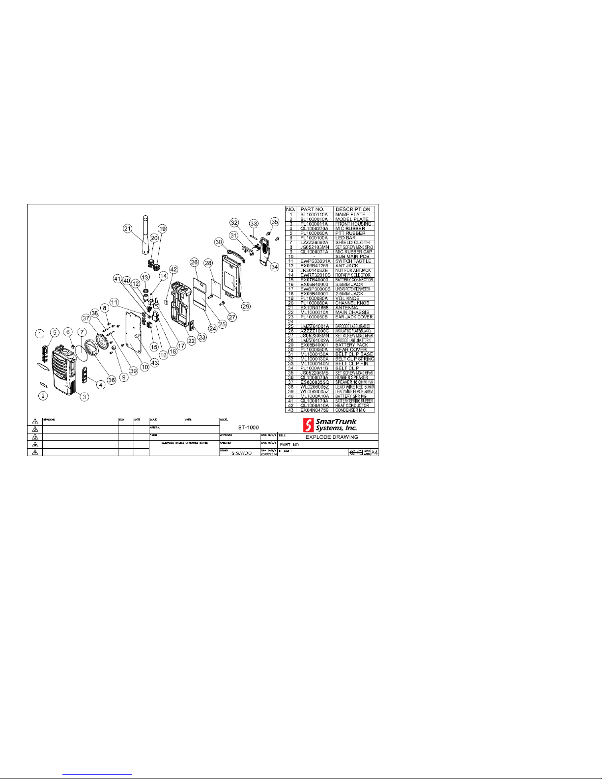
2. ST-1000 EXPLODED VIEW
Page 6
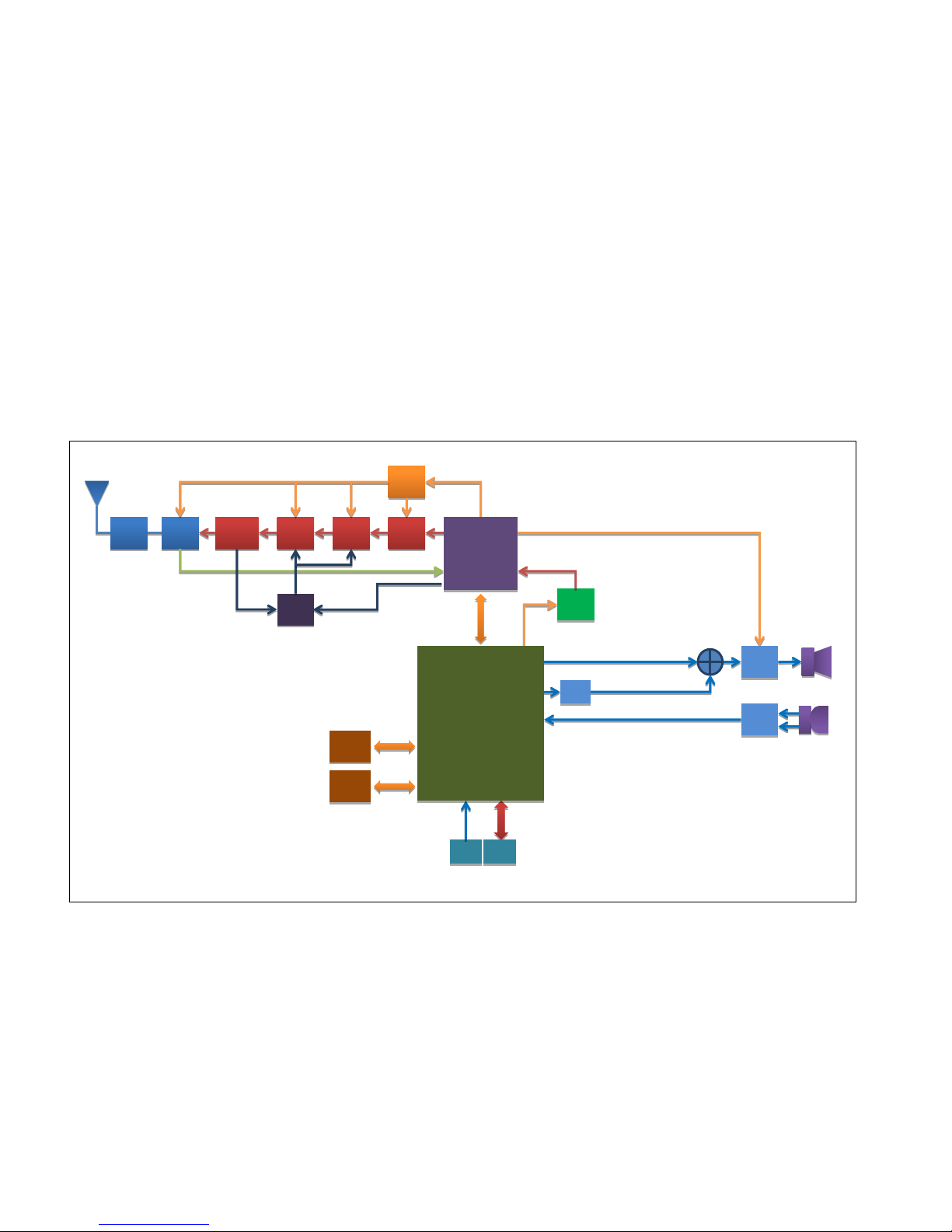
3. ST-1000 SIMPLIFIED DIAGRAM
LPF
Ant Sw
D1/D4
Final
AMP
Q2
Power
Detection
D2
Driver
Q3
Buffer
AMP
Q1
TX CTRL
[U3]
CLOCK
[Y2]
POWER
CTRL
[U3]
FLASH
MEMORY
[U4]
RAM
MEMORY
[U7]
PWM
SIDE
KEYS
SERIAL
PORT
Main Processor
[U8]
Radio
U1
MIC
AMP
[U11]
AUDIO
PA
[U9]
Page 7

Notes:
Page 8

ST-1000C SM R 1.0 SMARTRUNK SYSTEMS, INC.
8
4. - ST-1000 RF DESCRIPTION
4.1. Circuit Configuration
The receiver is a single receiver
with built-in DSP fully integrated.
Incoming signals from the
antenna, after passing through
LPF filter, are fed direct to the DSP
down converter to get the
baseband voice from 0Hz to
3500Hz.
Demodulated signals are fed to the
DSP processor where are filtered
and conditioned. This processor
also includes a high efficiency FSK
modem.
For digital demodulation, once the
data is decoded, and free of errors,
it is fed into the into a vocoder
firmware module, which converts
the data to voice.
Analog voice from the analog path
or the analog voice recovered from
the vocoder firmware, are fed into
an audio power amplifier direct
from a digital to analog converter.
Transmit signal frequency is
generated by integrated VCO and
PLL. RF frequency generated by
the integrated RF chip is amplified
into a 3-step amplifier then filtered
by a low pass filter to be applied to
the antenna.
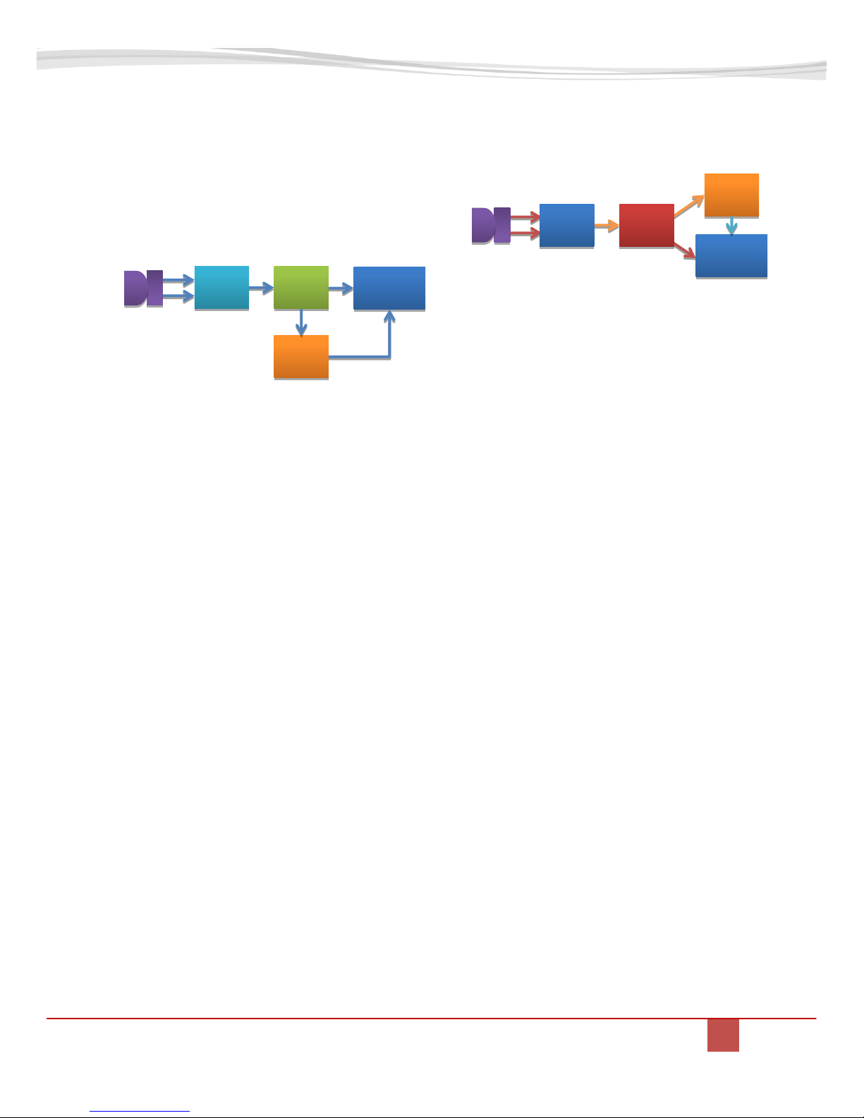
4.2. Receiver System
4.2.1. Front-end RF Receiver
Incoming RF signals from the
antenna are delivered to the
Receiver Unit and pass through a
Low-pass filter, antenna switching
diode, and then fed to the receiver
(U1) passing through a limiter
BPF.
4.2.2. ANALOG Audio Processing
The RF signal is tuned by U1,
which includes a base band DSP
audio processing, recovering flat
audio from DC up to 3500 hz.
The detected audio is amplified,
filtered and conditioned inside of
U8 which also includes a deemphasize filtering shape for
received audio signals by firmware.
The output of the filtered and
conditioned audio is delivered to
an audio power amplifier (U9) then
to the speaker passing through the
external audio connector switch.
4.2.3. Virtual Squelch Circuit
S/N ratio is measured by the
receiver (U1) as the result of the
analysis of the signal and the noise
of the carrier. The output is sent to
the main processor as a digital
frame, which is analyzed by radio
LPF
SWITCH
PROTECTION
FILTER
RECEIVER
[U1]
RECEIVER
[U1]
MAIN
PROCESSOR
[U8]
AMPLIFIER
[U9]
Page 9

ST-1000C SM R 1.0 SMARTRUNK SYSTEMS, INC.
9
firmware, removing noise then
qualifying the signal level. If the
signal level is higher than the
expected for the current
programmed squelch threshold,
then the processor analyzes the
expected signaling programmed on
the current channel table.
In case of not any signaling is
required, or the signal has been
detected, the processor opens the
virtual audio path, unmuting the
audio amplifier (U9).
4.2.4. Virtual VOLUME CONTROL
The potentiometer position (RV1) is
measured by one analog to digital
converter on the main processor
(U8. The firmware immediately
adjusts the processor path gain to
get the appropriate overall circuitry
volume control.
Minimum volume, emergency and
private audio level are controlled
only by software overriding the
information received from the DAC
on U8.
4.2.5. Sub audio signaling
Received sub audio signaling as
CTCSS and DCS are received and
processed and detected by the
receiver (U1). Once decoded, the
sub audio signaling is reported to
the processor where the firmware
compares it with the value
programmed into the current
channel programming.
If the received signaling matches
the channel programming, then
the main processor (U8) opens the
audio patch.
4.2.6. ANALOG AUDIBLE SIGNALING
DTMF signals, MDC1200 and tone
signals are processed and decoded
by the main processor (U8).
Decoded information or received
tone is analyzed by firmware on
the main processor (U8).
4.2.7. DIGITAL AUDIO PROCESSING
Digital received information is
processed by the receiver DSP (U1)
then delivered to the main
processor (U8), which includes a
very sensitive FSK modem.
Data decoded by the modem
firmware is transferred to the main
code, which de-encrypts the
information, checks the integrity,
corrects the wrong bits and extract
the audio information form the
received frame.
The portion of the data received,
error free, is moved to the vocoder
firmware module internally into
the main processor (U8).
The vocoder firmware re-builds the
audio from the compressed data
then applies filter it, adjust the
volume and fed it to the audio
power amplifier (U10) through one
RECEIVER
[U1]
AMPLIFIER
[U10]
MAIN
PROCESSOR
[U8]
VOCODER
U6]
Page 10
ST-1000C SM R 1.0 SMARTRUNK SYSTEMS, INC.
10
high definition digital to analog
converter.
4.3. Transmitter System
4.3.1. ANALOG TX SIGNAL
The AF signal from the internal
microphone (MK1) or external
microphone (J4) are processed as
differential signal, then it is
conditioned and transformed into
common mode by the microphone
pre-amplifier (U11).
The result of the conditioned inband filtered signal is fed to the
Main Processor (U8), which
provides audio gain control,
compander, emphasize, limitation,
encryption, etc. by software
algorithms.
The high audio band of the signals
from 300 to 3500 Hz are directly
fed to the transmitter (U1), which
performs a direct modulation of a
generated carrier.
Low frequency signaling audio is
fed directly to Y1 VC TXCO main
clock generator and U1 with a
corresponding balance controlled
by software.
4.3.2. DIGITAL TX AUDIO:
The AF signal from the internal
microphone (MK1) or external
microphone (J4) are fed directly to
the main processor (U8), which
perform the signal filtering, the
data codification, into especial
firmware block. The result of the
digitized information is processed
by a FEC (Frame Error Correction)
module, adding spare bits to
ensure high robustness to the
data, then it is encrypted and the
user related information as user ID
is added.
The final data frame is fed to the
modem code, which generates the
FDMA signals, controlling the
modulation of the Transmitter (U1)
through the VC TXCO for DC to
low frequencies and the direct
modulation for higher frequencies.
4.3.3. Driver and Final Amplifier Stages
Final RF is amplified on Q1
(2SC3356) then filtered to be fed to
Q3 (2SK3475) then finally
amplified by Q2 (2SK3476) up to 2
watts output power.
The transmit signal then passes
through the antenna switch D1
(BAR88) and is low-pass filtered to
suppress harmonic spurious
radiation before delivery to the
antenna.
AMPLIFIER
[U11]
MAIN
PROCESSOR
[U8]
TRANSMITTER
[U1]
VC TXCO
[Y1]
TRANSMITTER
[U1]
VC TXCO
[Y1]
MAIN
PROCESSOR
[U8]
AMPLIFIER
[U11]
Page 11

ST-1000C SM R 1.0 SMARTRUNK SYSTEMS, INC.
11
4.3.4. Automatic Transmit Power
Control
The RF power detector (BAS70)
detects transmitted feedback then
sends the readout to audio
processor U8. The special firmware
module compares the transmitted
power against the referred level
stored on current channel memory
adjusting the power control level
generated as reference by one DAC
output on the same processor (U8)
then amplified by U3 (MCP6241U)
controlling the gate current on Q1
and Q17.
Notes:
Page 12

ST-1000C SM R 1.0 SMARTRUNK SYSTEMS, INC.
12
5. RC-1000 ALIGNMENT
5.1. Introduction
The ST-1000 series is carefully
aligned in factory for the specified
performance, across the frequency
range depending for each version.
As the core of the radio is firmware
only, all processes are the result of
the internal feed-back where
alignment by user is not required.
Page 13

ST-1000C SM R 1.0 SMARTRUNK SYSTEMS, INC.
13
6. COMPLIMENTARY USER ALIGNMENT
Additional complimentary
parameters should be also aligned
on user login mode; it means the
user can align it as per the most
convenient way for particular radio
usage.
6.1. OPTION ALIGNMENT:
To access to the option alignment
menu, select Edit then Options
form the main software toolbar:
As soon as you click on Options…
the Options screen is popped up:
From this screen the user can
adjust some parameters as:
6.1.1. SQUELCH LEVEL:
ST-1000 supports a dBm scaled
squelch adjustment.
To set a desired squelch reference,
please select you desired squelch
level form the list:
Press [OK] to store it in the file.
The value will be updated after the
file is transferred to the radio.
6.1.2. ANNUNCIATION
You can enable or disable voice
annunciation.
To enable it, please check the
Voice box into the Options
alignment screen:
Page 14

ST-1000C SM R 1.0 SMARTRUNK SYSTEMS, INC.
14
6.1.3. Tones
You can enable or disable tones
generation when a key is pressed.
To enable it, please check the
Tones box into the Options
alignment screen:
6.1.4. Voice activated transmission
You can enable or disable the VOX
functionality for your radio.
To activate this feature, please
check the VOX-Enabled Box.
Once you check it, some additional
VOX control parameters are
enabled:
6.1.4.1. VOX sensitivity level
To adjust the VOX sensitivity level,
please press on the down-arrow of
the scroll-down box on the right
side of the Level label, and then
select the desired value. Low
values means less sensitivity (noisy
environments)
6.1.4.2. VOX inhibit on receive
In case you do not use
headphones, the audio received on
the speaker can be captured by the
microphone, setting the radio on
transmit mode. To avoid this issue,
you can automatically disable the
VOX feature when the radio is
receiving voice.
To enable this feature, check the
Vox Inhibit On Receive box:
Page 15

ST-1000C SM R 1.0 SMARTRUNK SYSTEMS, INC.
15
6.1.4.3. VOX delay
It is very common that when you
use VOX services in the radios, the
first words cannot be transmitted
because the voice detection and
the transmit power warm-up takes
time, losing part of the message.
SmarTrunk VOX delay can be
activated to avoid this issue.
When active Vox Delay service, the
radio is recording any audio
captured by the microphone and it
is real time analyzed by the
processor. In case audio is
detected, the radio sets on TX
mode, playing back the prerecorded audio after a delay to
ensure the receiver is already
getting the incoming voice. On this
way, no word is missed on the air.
To activate this feature, please
check the Vox Delay box:
6.1.5. Battery save
If the radio is not active on any
conversation, it is not necessary
that all radios internal
functionalities remain active.
To save battery by disabling some
radio functionalities temporary
when the radio is not involved on
any conversation, please check the
Battery Save box:
6.1.6. Microphone sensitivity
Depending how noisy the
environment is, or how sensitive is
the external microphone in use,
the microphone sensitivity must be
adjusted as per user comfort.
Please use the drop down list on
the right side of Mic Sensibility
label to select the desired
microphone sensitivity gain.
Page 16

ST-1000C SM R 1.0 SMARTRUNK SYSTEMS, INC.
16
Press OK to store your changes
into the radio file. The information
will be updated to the radio once
you transfer the file.
Page 17

7. ST-1000C SCHEMATIC
Title
Size D ocument Number Rev
Date: Sheet of
DM-140224-01 D
ST-1000 R1.2
C
1 1Tuesday, Oct ober 07, 2014
GPSE
C65
NC
L15
13nHD4
BAR63
TST4
1
1
C57
47pF
L16
NC
R53 330
L14
0
D3
HSM88AS
3
1
2
C56
0
C64
NC
RXD
C55
0
TXD
CHA
R54 330
SCR
CHD
R58 1K
C72
1nF
PTUN
CSFM
C192
1nF
t
RT1
33tk
1 2
C77 100nF
C137
100nF
R24
1K
U5
AT23DF321
CS
1
SO
2
WP
3
GND4SI
5
SCK
6
HOLD
7
VCC
8
L11
0
3VD
C167 NC
CHC
C142
NC
MEMORIES
3VD
C46
NC
MISO
MOSI
SCK
C34
33pF
3VD
PTTI
C35
56pF
U7
23K640
CS
1
SO
2
WP
3
GND4SI
5
SCK
6
HOLD
7
VCC
8
C119 10nF
SCK
MISO
R15
150
MOSI
C19
1nF
Q2
2SK34761
32
C37
15pF
DPOW
C47
15pF
BIAS
R12
47
C15 100nF
C16 150pF
TST5
1
1
R8
10K
R5
10K
R85 1K
R6
47K
LRX
MIC
CHC
L5
27nH
BAT
L2
BEAD
12
+7V
C9
1nF
R78 470
C13
150pF
R101
47K
C159
NC
R50
NC
C4
150pF
+
C5
106
3VD
R94 10K
C38
27pF
LCB1608-600
C160
1nF
L7
0
R79 1k
R21
100
C66
150pF
C156
1uF
C48
.5pF
D2
BAS70
+
C161 4.7uF
R23
100K
R82 1K
SW3
SW KEY-YM061
12
3 4
C40
.5pF
R20
100
SW1
SW KEY-YM061
12
3 4
C20
470pF
C155
NC
TP1
1
C82 1nF
TP2
1
R88 10K
TX5V
R2
100
TP3
1
C6
10nF
C88 NC
TP9
1
SW2
SW KEY-YM061
12
3 4
L4
.82uH
TP7
1
TP8
1
R103 1K
MICROPHONE
BAT
TP6
1
TP4
1
TP5
1
C10
1nF
R106
1K
R81
150K
TST1
1
1
R105
2K2
D1
BAR63
C29
10pF
R80
100
R102
100K
CSRM
C162
1nF
SIDE UP
C163
1nF
SIDE DOWN PTT
C83 1nF
MK1
MIC
1
2
C154 1uF
C173 1nF
R83
1K
3VD
U11
MCP6241U
Vin+
1
VSS
2
Vin-
3
Vout
4
VDD
5
C158
10uF
R45
1K
R112
10K
TST6
1
1
C107 1nF
MIC
AFO
C126
10nF
C78 1nF
C89 NC
LTX
RON
C71
100nF
3VD
C63
100nF
R48
NC
C73
2.2uF
C104 NC
R26
22KC 74
NC
R25
100K
C39
NC
DISC
SPM
C61
100nF
P2
ANT
1
1
R39
1K
R57 1K
C62
1nF
C84 1nF
C51
NC
TXDG
C49
100nF
C50
1nF
C164
1nF
TXDG
R96 1K
L12
15nH
C52
NC
TP10
1
C191 NC
C23
7pF
MODD
C53
NC
R17
560
R11
2K2
Q1
2SC3356
3
21
C94 NC
R1822C54
150pF
C17
10nF
MODD
L3
27nH
3VD
R10
470
C14
150pF
R4
22
C133 1nF
TX5V
C24
22p
GPSE
TMP
C32
15pF
L13
15nH
C45
NC
C79 NC
C58
1uF
R1347R14
47KC810nFC7150pF
R33
4K7
R7
22K
RSCK
RADIO CLOCK
Q3
2SK34751
32
C170 1nF
Y2
VC-TXCO
12
3 4C114
1nF
+
C76
22uF
L6
27nH
PWFB
C18
150pF
3VR
R27
100
+7V
L1
BEAD
12
C214 1nF
RCLK
+
C120
10uF
C3
10nF
C2
1nF
R86 1K
3VR 3VR
IRQR
+
C60
106
C85 1nF
5
C28
15pF
C22
100pF
+
C75
22uF
TX POWER SUPPLY
CHD
U2
HT7250
Vin
1
GND
2
Sht
3
Vout
5
BP
4
TX5V
C115
10nF
R30
10
+7V
+
C121
10uF
MISO
RSCK
RCLK
C122
1nF
PTTI
+
C116
10uF
C143
100nF
C117
10nF
U1
RDA1846
AVDD1
1
SCK
2
MOSI
3
AVDD2
4
XTAL1
5
XTAL2
6
MODE
7
CSR
8
AFO9NC110MIC11CC12AVDD313NC214RFIN15AVDD4
16
NC3
17
RFOUT
18
NC4
19
NC5
20
AVDD5
21
PABIAS
22
AVDD6
23
PDN
24
IO725IO626IO527IO4
28
MISO
29
INT
30
SUBD
31
SUB
32
GND
33
C69
100nF
R89 1K
C70
1nF
+7V
R60 1K
C68
1nF
C67
1nF
C12
1nF
C11
100nF
RDIO
VOL
R16
2M2
C21
150pF
C43
5pF
C27
2pF
C44
6.8pF
L10
13nH
C42
10pF
AFO
C86 1nF
L9
13nH
R74 47
C26
2.4pF
L8
13nH
C41
5pF
C25
NC
+
C131
10uF
IRQG
R47
470
C105 10K
EMIC
R87 1K
TXD
C81 1nF
C109
100nF
CSRM
R65 1K
U8
ATSAM4S8BA
ADVR
1
GND1
2
AD4
3
AD5
4
AD6
5
AD7
6
VDDIN
7
VDDOUT
8
AD0
9
AD1
10
AD8
11
VDDCORE
12
AD2
13
AD9
14
PA23
15
AD3
16
GND217VDDIO118PA1619PA1520SCK21MOSI22PA2423VDDCORE124PA2525PA2626MISO27CS028UTXD29URXD30PA831PA9
32
PB4
33
TXD0
34
RXD0
35
PA4
36
PA27
37
PA28
38
NRST
39
TST
40
PA29
41
CS2
42
CS3
43
PA2
44
VDDIO2
45
GND3
46
PWM1
47
PWM0
48
PB5
49
JTAGSEL
50
PB6
51
CS1
52
PB7
53
PB12
55
VDDCORE2
54
USBM
56
USBP
57
VDDIO3
58
DAC0
59
GND460XOUT
61
XIN
62
DAC1
63
VDDPLL
64
CSRM
SPM
C108 1nF
MIC-2954-03WS
MIC-2954-03WS
RDA POWER SUPPLY
CHA
U15
RT9163
VIN3VOUT
1
GND
2
+5V 3VR
RDIO
+
C194
106
C204
10nF
RSCK
U13
HT7233
Vin
1
GND
2
Sht
3
Vout
5
BP
4
R49
10K
3VD
+
C195 4.7uF
R108
10
C134
NC
PROCESSOR POWER SUPPLYAUDIO POWER SUPPLYMAIN POWER SUPPLY
+5V
+7V
+
C198
1uF
R107
0
C201 1nF
U12
RT9163
VIN3VOUT
1
GND
2
+
C196
10uF
+7V
R110
2.2
C203 1nF
C197NCC202
10nF
+5V
3VD
RON
RXDG
R115
100
C209 1uF
C205
10nF
+
C206 10uF
R72 1K C152 470p
U14
HT7233
Vin
1
GND
2
Sht
3
Vout
5
BP
4
C208 1nF
C1
1nF
RXD
R109
0
C207
10nF
C130 1nF
+
C199
1uF
AFO
R64 1K
MUTE
SSW
5VAF
+
C200
10uF
R99 47
DISC
C175 1nF
C111 1nF
C174 1K
3VD
LTX
BIAS
R84
NC
C189 NC
C30
NC
C59
NC
CSFM
C213
1nF
MIC
3VD
5VAF
PTTI
AFO
SSW
R59 1K
SmarTrunk Sy stems, INC
PCTRL
C168 NC
R63 1K
J4
3.5mm
3
5
4
2
1
TMP
MODD
R3
1K
BAT
DISC
R1
1K
TMP
R51
NC
References:
Pink components not loaded on ST-1000
R35
47K
R34
2K2
C124
10nF
POWER CONTROL
TX5V
EMIC
U3
MCP6241U
Vin+
1
VSS
2
Vin-
3
Vout
4
VDD
5
R36
82K
SCR
R31
470K
C113
10nF
R28
56K
MIC
C99
10nF
R93 1K
PCTRL
TX5V
C188 NC
R38
1K
R32
56K
C100
10nF
TX5V
R71 1K
R37
47KC125
220nF
R116
100
R95 1K
U4
PEB-916
ANT1AGND12AGND23AGND34VBAT5GND16NC7AGND48AGND59AGND610VCC
11
AGND7
12
NRES
13
AGND8
14
GND2
15
NC
16
AGND9
17
NC
18
AGND10
19
1PPS
20
AGND1121AGND1222AGND13
23
GND
24NC25
AGND14
26NC27
AGND1528AGND16
29
TX0
30
RX1
31
NC
32
GND
33
NC
34
AGND17
35
AGND18
36
C110 NC
MODD
R22 10K
IRQR
CHB
R29
4K7
C177 10uF
C123
1nF
DPOW
+5V
+
C136
10uF
C139
10nF
R43
10
U6
HT7233
Vin
1
GND
2
Sht
3
Vout
5
BP
4
C140
100nF
C141
1nF
R44 1K
3VD
C128
8PF
L17
ANT
R66 22k
R55 1K
LRX
R62 1K
C178 1uF
R92 1K
PTUN
CSFM
C187 NC
C179 1uF
CSG
SCK
CHA
PWFB
IRQR
C148 10nF
C171 NC
C169 NC
F1
C2Q 3
J6
CON4
1
2
3
4
C180 100nF
L18
BLM18K121
C176 1nF
J5
TG-2915
5
4
3
2
1
C193
1nF
C210
1nF
TST2
1
1
C106 22K
RV1
10k
3 1
2
4
5
3VD
3VD
C212
10nF
+7V
LCB1608-600
3VD
SCR
LRX
BATTERY
D5
LTST-C195KGJRKT
2 4
1 3
LTX
LEDS
R52
10K
R111
100K
C181 100nF
EMIC
R113
33K
RDIO
GPSE
TXD
R97 1K
PTUN
J2
ROTARY
3
4
5
6
782
1
C95
1nF
C96
1nF
C97
1nF
C98
1nF
CHB
C172 NC
C182 1uF
R98 47
C138
10nF
SPM
R56 1K
C165
NC
IRQG
U9
BH7824
CTLR
1
B_OUT
2
B_IN
3
SP_IN4SP1
5
VCC
6
GND
7
SP2
8
3VD
TST3
1
1
C144
10nF C146
1uF
C145
100nF
C183 1uF
C190 NC
R67
10K
R69
100K
5VAF
C151 2.2uF
R100 47
C147 1nF
C149
1uF
MUTE
R117
470
R91
22K
C150 100pF
C129 NC
R90 1K
C211
1nF
AUDIO PA
LS1
SPEAKER
VOL
C153 1uF
MOSI
C80 1nF
C184 100nF
SSW
R61 4K7
R77 1K
SPM
R76
1K
RXDG
CHB
CHC
C101 NC
C166 NC
R70 1K
C185 100nF
C186 NC
U10
LIS302
VDDIO
1
GND
2
VDD
3
GND
4
GND
5
VDD
6
CS7INT1
8
INT2
9
GND
10
GND
11
MISO
12
MOSI
13
SCK
14
SCK
MOSI
MISO
3VD
R68 1K
C157
100nF
CSG
SPM
CHD
R104 1K
MUTE
Page 18

11 ST-1000C COMPONENT LOCATOR
11.1 ST-1000C TOP LAYER COMPONENTS LOCATION
Page 19

ST-1000C SM R 1.0 SMARTRUNK SYSTEMS, INC.
19
11.2 ST-1000C BOTTOM LAYER COMPONENTS LOCATION
Page 20

ST-1000C SM R 1.0 SMARTRUNK SYSTEMS, INC.
20
12 ST-1000C PCB LAYOUT
12.1 ST-1000C TOP LAYER PCB LAYOUT
Page 21

ST-1000C SM R 1.0 SMARTRUNK SYSTEMS, INC.
21
12.2 ST-1000 BOTTOM LAYER PCB LAYOUT
Page 22

ST-1000C SM R 1.0 SMARTRUNK SYSTEMS, INC.
22
12.3 ST-1000C PCB GROUND LAYER
Page 23

ST-1000C SM R 1.0 SMARTRUNK SYSTEMS, INC.
23
12.4 ST-1000C PCB POWER LAYER
Page 24

ST-1000C SM R 1.0 SMARTRUNK SYSTEMS, INC.
24
13 ST-1000C BOM
ST-1000C BOM VERSION 1.0
NAME
DESCRIPTION
VALUE
SMARTRUNK
PN
MAIN P.C.B.
EPT100010A
C40
CAP CERAMIC 0.5PF 50V C0G 0402
.5pF
CK1059AK1A
C48
CAP CERAMIC 0.5PF 50V C0G 0402
.5pF
CK1059AK1A
C150
CAP CERAMIC 100PF 50V NP0 0402
100pF
CK1101AK5A
C19
CAP CER 1000PF 50V 0603 LOW DIST
1nF
CK1102AD5XR
C1
CAP 1000PF 50V CERAMIC X7R 0402
1nF
CK1102AK5X
C2
CAP 1000PF 50V CERAMIC X7R 0402
1nF
CK1102AK5X
C9
CAP 1000PF 50V CERAMIC X7R 0402
1nF
CK1102AK5X
C10
CAP 1000PF 50V CERAMIC X7R 0402
1nF
CK1102AK5X
C12
CAP 1000PF 50V CERAMIC X7R 0402
1nF
CK1102AK5X
C50
CAP 1000PF 50V CERAMIC X7R 0402
1nF
CK1102AK5X
C62
CAP 1000PF 50V CERAMIC X7R 0402
1nF
CK1102AK5X
C67
CAP 1000PF 50V CERAMIC X7R 0402
1nF
CK1102AK5X
C68
CAP 1000PF 50V CERAMIC X7R 0402
1nF
CK1102AK5X
C70
CAP 1000PF 50V CERAMIC X7R 0402
1nF
CK1102AK5X
C72
CAP 1000PF 50V CERAMIC X7R 0402
1nF
CK1102AK5X
C78
CAP 1000PF 50V CERAMIC X7R 0402
1nF
CK1102AK5X
C80
CAP 1000PF 50V CERAMIC X7R 0402
1nF
CK1102AK5X
C81
CAP 1000PF 50V CERAMIC X7R 0402
1nF
CK1102AK5X
C82
CAP 1000PF 50V CERAMIC X7R 0402
1nF
CK1102AK5X
C83
CAP 1000PF 50V CERAMIC X7R 0402
1nF
CK1102AK5X
C84
CAP 1000PF 50V CERAMIC X7R 0402
1nF
CK1102AK5X
C85
CAP 1000PF 50V CERAMIC X7R 0402
1nF
CK1102AK5X
C86
CAP 1000PF 50V CERAMIC X7R 0402
1nF
CK1102AK5X
C95
CAP 1000PF 50V CERAMIC X7R 0402
1nF
CK1102AK5X
C96
CAP 1000PF 50V CERAMIC X7R 0402
1nF
CK1102AK5X
C97
CAP 1000PF 50V CERAMIC X7R 0402
1nF
CK1102AK5X
C98
CAP 1000PF 50V CERAMIC X7R 0402
1nF
CK1102AK5X
C108
CAP 1000PF 50V CERAMIC X7R 0402
1nF
CK1102AK5X
C111
CAP 1000PF 50V CERAMIC X7R 0402
1nF
CK1102AK5X
C114
CAP 1000PF 50V CERAMIC X7R 0402
1nF
CK1102AK5X
C122
CAP 1000PF 50V CERAMIC X7R 0402
1nF
CK1102AK5X
C130
CAP 1000PF 50V CERAMIC X7R 0402
1nF
CK1102AK5X
C133
CAP 1000PF 50V CERAMIC X7R 0402
1nF
CK1102AK5X
C147
CAP 1000PF 50V CERAMIC X7R 0402
1nF
CK1102AK5X
C155
CAP 1000PF 50V CERAMIC X7R 0402
1nF
CK1102AK5X
Page 25

ST-1000C SM R 1.0 SMARTRUNK SYSTEMS, INC.
25
C160
CAP 1000PF 50V CERAMIC X7R 0402
1nF
CK1102AK5X
C162
CAP 1000PF 50V CERAMIC X7R 0402
1nF
CK1102AK5X
C163
CAP 1000PF 50V CERAMIC X7R 0402
1nF
CK1102AK5X
C164
CAP 1000PF 50V CERAMIC X7R 0402
1nF
CK1102AK5X
C170
CAP 1000PF 50V CERAMIC X7R 0402
1nF
CK1102AK5X
C173
CAP 1000PF 50V CERAMIC X7R 0402
1nF
CK1102AK5X
C175
CAP 1000PF 50V CERAMIC X7R 0402
1nF
CK1102AK5X
C176
CAP 1000PF 50V CERAMIC X7R 0402
1nF
CK1102AK5X
C192
CAP 1000PF 50V CERAMIC X7R 0402
1nF
CK1102AK5X
C193
CAP 1000PF 50V CERAMIC X7R 0402
1nF
CK1102AK5X
C201
CAP 1000PF 50V CERAMIC X7R 0402
1nF
CK1102AK5X
C203
CAP 1000PF 50V CERAMIC X7R 0402
1nF
CK1102AK5X
C208
CAP 1000PF 50V CERAMIC X7R 0402
1nF
CK1102AK5X
C210
CAP 1000PF 50V CERAMIC X7R 0402
1nF
CK1102AK5X
C211
CAP 1000PF 50V CERAMIC X7R 0402
1nF
CK1102AK5X
C213
CAP 1000PF 50V CERAMIC X7R 0402
1nF
CK1102AK5X
C214
CAP 1000PF 50V CERAMIC X7R 0402
1nF
CK1102AK5X
C4
CAP CER 150PF 50V C0G 0402
150pF
CK1151AK5A
C7
CAP CER 150PF 50V C0G 0402
150pF
CK1151AK5A
C13
CAP CER 150PF 50V C0G 0402
150pF
CK1151AK5A
C14
CAP CER 150PF 50V C0G 0402
150pF
CK1151AK5A
C16
CAP CER 150PF 50V C0G 0402
150pF
CK1151AK5A
C18
CAP CER 150PF 50V C0G 0402
150pF
CK1151AK5A
C54
CAP CER 150PF 50V C0G 0402
150pF
CK1151AK5A
C66
CAP CER 150PF 50V C0G 0402
150pF
CK1151AK5A
C57
CAP CER 47PF 50V 5% NP0 0603
47pF
CK1470AD4AR
C35
CAP CERAMIC 56PF 100V 10% NPO 0603
56pF
CK1560AD4A
C27
CAP CERAMIC 2PF 100V NPO 0603
2pF
CK4020AD1A
C41
CAP CER 10PF 250V 5% NPO 0603
10pF
CK9100AD2A
C42
CAP CER 10PF 250V 5% NPO 0603
10pF
CK9100AD2A
C22
CAP CER 100PF 100V 10% NP0 0603
100pF
CK4101AD5A
C28
CAP CER 15PF 100V 10% NPO 0603
15pF
CK4150AD5A
C29
CAP CER 15PF 100V 10% NPO 0603
15pF
CK4150AD5A
C32
CAP CER 15PF 100V 10% NPO 0603
15pF
CK4150AD5A
C37
CAP CER 15PF 100V 10% NPO 0603
15pF
CK4150AD5A
C47
CAP CER 15PF 100V 10% NPO 0603
15pF
CK4150AD5A
C20
CAP CER 470PF 100V 10% NPO 0603
470pF
CK4470AD5A
C21
CAP CERAMIC 150PF 100V COG 5% 0603
150pF
CK4151AD4A
C26
CAP CERAMIC 2.4PF 100V NPO 0603
2.4pF
CK4249AD1A
C34
CAP CER 33PF 100V 5% NPO 0603
33pF
CK4330AD4A
C3
CAP CERAMIC .01UF 50V X7R 0402
10nF
CK5103AK5X
C6
CAP CERAMIC .01UF 50V X7R 0402
10nF
CK5103AK5X
C17
CAP CERAMIC .01UF 50V X7R 0402
10nF
CK5103AK5X
C99
CAP CERAMIC .01UF 50V X7R 0402
10nF
CK5103AK5X
Page 26

ST-1000C SM R 1.0 SMARTRUNK SYSTEMS, INC.
26
C100
CAP CERAMIC .01UF 50V X7R 0402
10nF
CK5103AK5X
C113
CAP CERAMIC .01UF 50V X7R 0402
10nF
CK5103AK5X
C115
CAP CERAMIC .01UF 50V X7R 0402
10nF
CK5103AK5X
C117
CAP CERAMIC .01UF 50V X7R 0402
10nF
CK5103AK5X
C125
CAP CERAMIC .22UF 50V X7R 0402
220nF
CK0224AK5T
C126
CAP CERAMIC .01UF 50V X7R 0402
10nF
CK5103AK5X
C144
CAP CERAMIC .01UF 50V X7R 0402
10nF
CK5103AK5X
C202
CAP CERAMIC .01UF 50V X7R 0402
10nF
CK5103AK5X
C204
CAP CERAMIC .01UF 50V X7R 0402
10nF
CK5103AK5X
C205
CAP CERAMIC .01UF 50V X7R 0402
10nF
CK5103AK5X
C207
CAP CERAMIC .01UF 50V X7R 0402
10nF
CK5103AK5X
C212
CAP CERAMIC .01UF 50V X7R 0402
10nF
CK5103AK5X
C124
CAP CERAMIC .01UF 50V X7R 0402
10nF
CK5103AK5X
C119
CAP CERAMIC .01UF 50V X7R 0402
10nF
CK5103AK5X
C8
CHIP/C 0.01UF 50WX K X7R 0603
10nF
CK1103AD5XR
C5
CAP CER 10UF 10V Y5V 0805
10uF
CK0106AB7R
C60
CAP CER 10UF 10V Y5V 0805
10uF
CK0106AB7R
C116
CAP CER 10UF 10V Y5V 0805
10uF
CK0106AB7R
C121
CAP CER 10UF 10V Y5V 0805
10uF
CK0106AB7R
C194
CAP CER 10UF 10V Y5V 0805
10uF
CK0106AB7R
C196
CAP CER 10UF 10V Y5V 0805
10uF
CK0106AB7R
C200
CAP CER 10UF 10V Y5V 0805
10uF
CK0106AB7R
C206
CAP CER 10UF 10V Y5V 0805
10uF
CK0106AB7R
C11
CAP .10UF 16V CERAMIC Y5V 0402
100nF
CK5104AK5X
C15
CAP .10UF 16V CERAMIC Y5V 0402
100nF
CK5104AK5X
C49
CAP .10UF 16V CERAMIC Y5V 0402
100nF
CK5104AK5X
C61
CAP .10UF 16V CERAMIC Y5V 0402
100nF
CK5104AK5X
C63
CAP .10UF 16V CERAMIC Y5V 0402
100nF
CK5104AK5X
C69
CAP .10UF 16V CERAMIC Y5V 0402
100nF
CK5104AK5X
C71
CAP .10UF 16V CERAMIC Y5V 0402
100nF
CK5104AK5X
C77
CAP .10UF 16V CERAMIC Y5V 0402
100nF
CK5104AK5X
C145
CAP .10UF 16V CERAMIC Y5V 0402
100nF
CK5104AK5X
C180
CAP .10UF 16V CERAMIC Y5V 0402
100nF
CK5104AK5X
C181
CAP .10UF 16V CERAMIC Y5V 0402
100nF
CK5104AK5X
C184
CAP .10UF 16V CERAMIC Y5V 0402
100nF
CK5104AK5X
C185
CAP .10UF 16V CERAMIC Y5V 0402
100nF
CK5104AK5X
C198
CAP CERAMIC 1UF 16V Y5V 0603
1uF
CK5105AD7RR
C199
CAP CERAMIC 1UF 16V Y5V 0603
1uF
CK5105AD7RR
C151
CAP CER 2.2UF 16V Y5V 0603
2.2uF
CK5225AD7R
C58
CAP CER 1.0UF 6.3V X5R 20% 0402
1uF
CK6105AK6T
C146
CAP CER 1.0UF 6.3V X5R 20% 0402
1uF
CK6105AK6T
C154
CAP CER 1.0UF 6.3V X5R 20% 0402
1uF
CK6105AK6T
C156
CAP CER 1.0UF 6.3V X5R 20% 0402
1uF
CK6105AK6T
C153
CAP CER 1.0UF 6.3V X5R 20% 0402
1uF
CK6105AK6T
Page 27

ST-1000C SM R 1.0 SMARTRUNK SYSTEMS, INC.
27
C178
CAP CER 1.0UF 6.3V X5R 20% 0402
1uF
CK6105AK6T
C179
CAP CER 1.0UF 6.3V X5R 20% 0402
1uF
CK6105AK6T
C182
CAP CER 1.0UF 6.3V X5R 20% 0402
1uF
CK6105AK6T
C183
CAP CER 1.0UF 6.3V X5R 20% 0402
1uF
CK6105AK6T
C209
CAP CER 1.0UF 6.3V X5R 20% 0402
1uF
CK6105AK6T
C120
CAP CER 10UF 6.3V X5R 20% 0603
10uF
CK6106AD6T
C158
CAP CER 10UF 6.3V X5R 20% 0603
10uF
CK6106AD6T
C177
CAP CER 10UF 6.3V X5R 20% 0603
10uF
CK6106AD6T
C131
CAP CER 10UF 6.3V X5R 20% 0603
10uF
CK6106AD6T
C73
CAP CER 2.2UF 4.0V X5R 20% 0402
2.2uF
CK6225AK6T
C75
CAP CER 22UF 6.3V 20% X5R 0603
22uF
CK6226AD6T
C76
CAP CER 22UF 6.3V 20% X5R 0603
22uF
CK6226AD6T
C161
CAP CER 4.7UF 6.3V 20% X5R 0402
4.7uF
CK6475AK6T
C195
CAP CER 4.7UF 6.3V 20% X5R 0402
4.7uF
CK6475AK6T
C43
CAP CER 5PF 250V C0G SMD
5pF
CK9050AD1A
C23
CAP CER 7PF 250V NP0 0603
7pF
CK9070AD1A
C24
CAP CER 22PF 250V 5% NP0 0603
22pF
CK9220AD4A
C38
CAP CER 27PF 250V 5% NP0 0603
27pF
CK9270AD4A
C152
CHIP/C 470PF 50V 10% X7R 0402
470pF
CK1471AK4A
C159
CHIP/C 470PF 50V 10% X7R 0402
470pF
CK1471AK4A
C44
CAP CERAMIC 6.8PF 250V COG SMD
6.8pF
CK9689AD4A
D1
DIODE RF PIN 80V 100MA SC79
BAR88
EDBAR0886Y
D4
DIODE RF SGL 50V 100MA SOD-323
BAR63
EDBAR0063Y
D3
SILICON SCHOTTKY BARRIER DIODE
HSM88AS
EDHSM0088A
Y2
12.8MHZ OSCILLATOR VC-TXCO
VC-TXCO
EFO128000Y
D5
LED GREEN/RED BICOLOR 0606 SMD
LTST-
C195KGJRKT
EX01Y40203
F1
FUSE 3A 32V 0603 FAST C2Q
C2Q 3
EX02Y40258
R30
RES 10 OHM 1/16W 5% 0402 SMD
10
RCY041004Z
R108
RES 10 OHM 1/16W 5% 0402 SMD
10
RCY041004Z
R109
RES 0 OHM 1/16W 5% 0402 SMD
0
RCY040004Z
R107
RES 0 OHM 1/16W 5% 0402 SMD
0
RCY040004Z
R2
RES 100 OHM 1/16W 5% 0402 SMD
100
RCY041014Z
R20
RES 100 OHM 1/16W 5% 0402 SMD
100
RCY041014Z
R21
RES 100 OHM 1/16W 5% 0402 SMD
100
RCY041014Z
R27
RES 100 OHM 1/16W 5% 0402 SMD
100
RCY041014Z
R80
RES 100 OHM 1/16W 5% 0402 SMD
100
RCY041014Z
R115
RES 100 OHM 1/16W 5% 0402 SMD
100
RCY041014Z
R116
RES 100 OHM 1/16W 5% 0402 SMD
100
RCY041014Z
R1
RES 1.0K OHM 1/16W 5% 0402 SMD
1K
RCY041024Z
R3
RES 1.0K OHM 1/16W 5% 0402 SMD
1K
RCY041024Z
R24
RES 1.0K OHM 1/16W 5% 0402 SMD
1K
RCY041024Z
R39
RES 1.0K OHM 1/16W 5% 0402 SMD
1K
RCY041024Z
R44
RES 1.0K OHM 1/16W 5% 0402 SMD
1K
RCY041024Z
R45
RES 1.0K OHM 1/16W 5% 0402 SMD
1K
RCY041024Z
Page 28

ST-1000C SM R 1.0 SMARTRUNK SYSTEMS, INC.
28
R55
RES 1.0K OHM 1/16W 5% 0402 SMD
1K
RCY041024Z
R56
RES 1.0K OHM 1/16W 5% 0402 SMD
1K
RCY041024Z
R57
RES 1.0K OHM 1/16W 5% 0402 SMD
1K
RCY041024Z
R58
RES 1.0K OHM 1/16W 5% 0402 SMD
1K
RCY041024Z
R63
RES 1.0K OHM 1/16W 5% 0402 SMD
1K
RCY041024Z
R64
RES 1.0K OHM 1/16W 5% 0402 SMD
1K
RCY041024Z
R65
RES 1.0K OHM 1/16W 5% 0402 SMD
1K
RCY041024Z
R68
RES 1.0K OHM 1/16W 5% 0402 SMD
1K
RCY041024Z
R70
RES 1.0K OHM 1/16W 5% 0402 SMD
1K
RCY041024Z
R71
RES 1.0K OHM 1/16W 5% 0402 SMD
1K
RCY041024Z
R72
RES 1.0K OHM 1/16W 5% 0402 SMD
1K
RCY041024Z
R76
RES 1.0K OHM 1/16W 5% 0402 SMD
1K
RCY041024Z
R77
RES 1.0K OHM 1/16W 5% 0402 SMD
1K
RCY041024Z
R79
RES 1.0K OHM 1/16W 5% 0402 SMD
1k
RCY041024Z
R82
RES 1.0K OHM 1/16W 5% 0402 SMD
1K
RCY041024Z
R83
RES 1.0K OHM 1/16W 5% 0402 SMD
1K
RCY041024Z
R85
RES 1.0K OHM 1/16W 5% 0402 SMD
1K
RCY041024Z
R87
RES 1.0K OHM 1/16W 5% 0402 SMD
1K
RCY041024Z
R89
RES 1.0K OHM 1/16W 5% 0402 SMD
1K
RCY041024Z
R90
RES 1.0K OHM 1/16W 5% 0402 SMD
1K
RCY041024Z
R92
RES 1.0K OHM 1/16W 5% 0402 SMD
1K
RCY041024Z
R103
RES 1.0K OHM 1/16W 5% 0402 SMD
1K
RCY041024Z
R106
RES 1.0K OHM 1/16W 5% 0402 SMD
1K
RCY041024Z
C174
RES 1.0K OHM 1/16W 5% 0402 SMD
1K
RCY041024Z
R5
RES 10K OHM 1/16W 5% 0402 SMD
10K
RCY041034Z
R8
RES 10K OHM 1/16W 5% 0402 SMD
10K
RCY041034Z
R22
RES 10K OHM 1/16W 5% 0402 SMD
10K
RCY041034Z
R52
RES 10K OHM 1/16W 5% 0402 SMD
10K
RCY041034Z
R67
RES 10K OHM 1/16W 5% 0402 SMD
10K
RCY041034Z
R88
RES 10K OHM 1/16W 5% 0402 SMD
10K
RCY041034Z
R94
RES 10K OHM 1/16W 5% 0402 SMD
10K
RCY041034Z
C105
RES 10K OHM 1/16W 5% 0402 SMD
10K
RCY041034Z
R112
RES 10K OHM 1/16W 5% 0402 SMD
10K
RCY041034Z
R23
RES 100K OHM 1/16W 5% 0402 SMD
100K
RCY041044Z
R25
RES 100K OHM 1/16W 5% 0402 SMD
100K
RCY041044Z
R69
RES 100K OHM 1/16W 5% 0402 SMD
100K
RCY041044Z
R81
RES 100K OHM 1/16W 5% 0402 SMD
100K
RCY041044Z
R102
RES 100K OHM 1/16W 5% 0402 SMD
100K
RCY041044Z
R111
RES 100K OHM 1/16W 5% 0402 SMD
100K
RCY041044Z
R28
RES 56K OHM 1/16W 5% 0402 SMD
56K
RCY045634Z
R4
RES 22 OHM 1/16W 5% 0402 SMD
22
RCY042204Z
R18
RES 22 OHM 1/16W 5% 0402 SMD
22
RCY042204Z
R11
RES 2.2K OHM 1/16W 5% 0402 SMD
2K2
RCY042224Z
R34
RES 2.2K OHM 1/16W 5% 0402 SMD
2K2
RCY042224Z
Page 29

ST-1000C SM R 1.0 SMARTRUNK SYSTEMS, INC.
29
R105
RES 2.2K OHM 1/16W 5% 0402 SMD
2K2
RCY042224Z
R7
RES 22K OHM 1/16W 5% 0402 SMD
22K
RCY042234Z
R26
RES 22K OHM 1/16W 5% 0402 SMD
22k
RCY042234Z
R91
RES 22K OHM 1/16W 5% 0402 SMD
22k
RCY042234Z
C106
RES 22K OHM 1/16W 5% 0402 SMD
22k
RCY042234Z
R110
RES 2.2 OHM 1/16W 5% 0402 SMD
2.2
RCY042294Z
R53
RES 330 OHM 1/16W 5% 0402 SMD
330
RCY043314Z
R54
RES 330 OHM 1/16W 5% 0402 SMD
330
RCY043314Z
R113
RES 33K OHM 1/16W 5% 0402 SMD
33K
RCY043334Z
R10
RES 470 OHM 1/16W 5% 0402 SMD
470
RCY044714Z
R47
RES 470 OHM 1/16W 5% 0402 SMD
470
RCY044714Z
R117
RES 470 OHM 1/16W 5% 0402 SMD
470
RCY044714Z
R33
RES 4.7K OHM 1/16W 5% 0402 SMD
4K7
RCY044724Z
R6
RES 47K OHM 1/16W 5% 0402 SMD
47K
RCY044734Z
R14
RES 47K OHM 1/16W 5% 0402 SMD
47K
RCY044734Z
R35
RES 47K OHM 1/16W 5% 0402 SMD
47K
RCY044734Z
R37
RES 47K OHM 1/16W 5% 0402 SMD
47K
RCY044734Z
R101
RES 47K OHM 1/16W 5% 0402 SMD
47K
RCY044734Z
R31
RES 470K OHM 1/16W 5% 0402 SMD
470K
RCY044744Z
R17
RES 560 OHM 1/16W 5% 0402 SMD
560
RCY045614Z
R32
RES 56K OHM 1/16W 5% 0402 SMD
56K
RCY045634Z
R36
RES 82K OHM 1/16W 5% 0402 SMD
82K
RCY048234Z
L14
RES 0.0 OHM 1/16W 0603SMD
0
RCY060004ZR
C55
RES 0.0 OHM 1/16W 0603SMD
0
RCY060004ZR
C56
RES 0.0 OHM 1/16W 0603SMD
0
RCY060004ZR
L7
RES 0.0 OHM 1/16W 0603SMD
0
RCY060004ZR
L11
RES 0.0 OHM 1/16W 0603SMD
0
RCY060004ZR
R15
RES 150 OHM 1/10W 5% 0603 SMD
150
RCY061514Z
R16
RES 2.2M OHM 1/10W 5% 0603 SMD
2M2
RCY062254Z
R12
RES 47 OHM 1/16 5% 0603 SMD
47
RCY064704ZR
R13
RES 47 OHM 1/16 5% 0603 SMD
47
RCY064704ZR
RT1
THERMISTOR
33tk
RTU143334Y
Q1
TRANSISTOR
2SC3356
TY2SC3356Z
Q3
TRANSISTOR
2SK3475
TY2SK3475Z
Q2
TRANSISTOR
2SK3476
TY2SK3476Z
L1
BEAD COIL
BEAD
YCBAD18592
L2
BEAD COIL
BEAD
YCBAD18592
L18
BEAD COIL
BLM18K121
YCBAD18592
L12
INDUCTOR
15nH
YCMCI1533D
L13
INDUCTOR
15nH
YCMCI1533D
L3
INDUCTOR
27nH
YCMCI2733D
L6
INDUCTOR
27nH
YCMCI2733D
L4
INDUCTOR
.82uH
YCMCI8243D
L5
SPRING COIL
27nH
YCSPG18424
Page 30

ST-1000C SM R 1.0 SMARTRUNK SYSTEMS, INC.
30
L8
SPRING COIL
13nH
YCSPG18426
L9
SPRING COIL
13nH
YCSPG18426
L10
SPRING COIL
13nH
YCSPG18426
L15
SPRING COIL
13nH
YCSPG18426
U13
IC
HT7233
YNHT07233Z
U14
IC
HT7233
YNHT07233Z
U2
LDO LINEAR REGULATOR 5V
HT7250
YNHT07250Z
U3
OPERATIONAL AMPLIFIER
MCP6241U
YNMR6241UT
U11
OPERATIONAL AMPLIFIER
MCP6241U
YNMR6241UT
U1
SINGLE CHIP RADIO TRANSCEIVER
RDA1846
YNRD01846Z
U9
AUDIO AMPLIFIER
BH7824
YNRO07824Z
U12
5V LINEAR REGULATOR
XC6201
YNTX1P502P
U15
5V LINEAR REGULATOR
XC6201
YNTX1P502P
D2
DIODE SCHOTTKY 70V 70MA SOT23
RB705D
EDBAS0070Y
R74
RES 47 OHM 1/16W 5% 0402 SMD
47
RCY044704Z
R98
RES 47 OHM 1/16W 5% 0402 SMD
47
RCY044704Z
R99
RES 47 OHM 1/16W 5% 0402 SMD
47
RCY044704Z
R100
RES 47 OHM 1/16W 5% 0402 SMD
47
RCY044704Z
U8
IC MCU 32BIT 512KB FLASH 64LQFP
ATSAM4S8BA
YNATSAM04S
14 ST-1000C MECHANICAL BOM
ST-1000C BOM (MECHANICAL)
LOCATION
DESCRIPTION
VALUE
SMARTRUNK PN
J2
ROTARY SELECTOR
ROTARY
EWRT32010S
RV1
LINEAR POTENTIOMETER WITH SWITCH
10K
EWSP30000S
J4
3.5MM JACK 3 CONTACTS SINGLE SWITCH
3.5MM
EX06B40000
J5
2.5MM JACK 3 CONTACTS SINGLE SWITCH
2.5MM
EX06B40001
SPEAKER 16 OHM 1W
SP
ES800835SQ
SPK
SHIELD CLOTH
LZZZZ6092A
MK1
CONDUCTOR MIC
MIC
EX04N04759
SW1
SWITCH TACTILE SPST-NO 0.05A 12V
SW KEY -YM061
EWPS33091X
SW2
SWITCH TACTILE SPST-NO 0.05A 12V
SW KEY -YM061
EWPS33091X
SW3
SWITCH TACTILE SPST-NO 0.05A 12V
SW KEY -YM061
EWPS33091X
MAIN CHASSIS
ML1000010X
VOL KNOB
PL1000090A
CHANNEL KNOB
PL1000080A
SPK
RUBBER SPEAKER
QL1000070A
Page 31

ST-1000C SM R 1.0 SMARTRUNK SYSTEMS, INC.
31
EAR JACK COVER
PL1000030B
BATTERY SPRING RUBBER
QL1000170A
BATTERY SPRING
ML1000A10A
J6
BATTERY CONNECTOR
BATT
EX07B40000
ANT JACK
EX06B41269
NUT FOR ANT. JACK
JN301403ZE
SPK
LEAD WIRE BLACK 50MM
WL0006005Z
SPK
LEAD WIRE RED 50MM
WL0206005Z
FRONT HOUSING
PL1000011A
LED BAR
PL1000100A
MIC RUBBER
QL1000270A
PTT RUBBER
PL1000060A
REAR COVER
PL1000050A
REAR COVER
SET SCREW M3X0.5PX6 BLACK
JS052206MB
MAIN CHASSIS
SET SCREW M3X0.5PX8
JS052308MN
MAIN PCB
SET SCREW M2X0.5PX4
JS052103MN
AC ADAPTOR
ETSGS2U009
ANTENNA
EX10N41858
MIC RUBBER CAP
QL1000071A
MAIN CHASSIS
INSULATING PLATE (BLACK)
XZZZZ1000C
HEAT CONDUCTOR 8mmX5mmX2.5tmm
QL1000A10A
Page 32

ST-1000C SM R 1.0 SMARTRUNK SYSTEMS, INC.
32
15 ACCESSORY PORT:
Speaker Microphone Pin Out
3.5mm Plug
Sleeve
Mic – PTT Rx Data (to the radio)
Ring
Mic +
Tip
+V (from the radio)
2.5mm Plug
Sleeve
Speaker – PTT Data GND
Ring
TX Data (from the radio)
Tip
Speaker +
Connect Sleeve to Sleeve for PTT
Page 33

ST-1000C SM R 1.0 SMARTRUNK SYSTEMS, INC.
33
Page 34

ST-1000C SM R 1.0 SMARTRUNK SYSTEMS, INC.
34
16 ST-1000C SERVICE MANUAL REVISIONS
AUTHOR
RELEASE
DATE
REMARKS
DANIEL MARTIN
1.0
AUG-2014
INITIAL RELEASE VERSION
Page 35

ST-1000C SM R 1.0 SMARTRUNK SYSTEMS, INC.
35
Copyright 2014
Printed in Malaysia
www.smartrunk.com
ST-1000C SM R1.0
 Loading...