

Page 1

SmarTrunk II
System Overview
Revision 9
March 2004
Benelec Pty Ltd
Unit 2 / 581-587 Gardeners Rd
Mascot NSW 2020
T : +61 2 93647000 F: +61 2 93647099 E:david@benelec.com.au
Page 2

System Overview
SmarTrunk Systems, Inc., was founded in 1979 as Selectone Corporation, a
privately held California corporation, and quickly became a leading manufacturer of tone signaling and voice encryption equipment for the mobile communications industry.
In 1992, the company introduced the original SmarTrunk system as a lowcost trunking protocol for radiotelephone systems in developing countries. In
1994, a second- generation system was introduced,
SmarTrunk II, with more features and a faster, more secure digital signaling
protocol. Since then, SmarTrunk II has become an industry standard radio
trunking protocol in more than 98 countries.
About SmarTrunk Systems, Inc.
Recognizing the growing importance of the SmarTrunk II product line, the
company’s corporate name was changed to SmarTrunk Systems, Inc., in
early 1996. In June 2000, the company’s original Selectone product line was
sold to Communications Specialists, Inc.
In July, 2001, after nearly 30 years in the land mobile business, SmarTrunk’s
founder and CEO retired and sold the company to Ranger Communications,
Inc. SmarTrunk Systems, Inc., is now a wholly owned subsidiary of Ranger
Communications, Inc. of National City (San Diego), California. Ranger’s 30+
years of experience in the manufacturing business, furthers SmarTrunk’s
position as the leading supplier of radio trunking systems. Since 2001, the
ST-510 SmarTrunk II Switch and the SmarTrunk II feature set has been
greatly expanded.
2
Page 3

Table of Contents
C
Section 1 • Things You Always Wanted to Know About Trunking…5
Introduction .......................................................................................................................5
What is Trunking? .............................................................................................................5
Trunking in Land Mobile Radio (LMR) Systems.................................................................5
The Trunking Advantage ................................................................................................... 6
Rules Regarding VHF and UHF Trunking in the United States ........................................... 7
Centralized vs. Decentralized Trunking Systems ...............................................................8
Section 2 • System Highlights ................................................... 9
Wireless Solutions Supported by SmarTrunk II .................................................................. 9
System Requirements ....................................................................................................10
Section 3 • Types of Calls and Methods of Operation .................11
Using SmarTrunk II For Radio Dispatch Applications ................................... 11
Mobile to Group Call ....................................................................................................... 11
Mobile to Mobile Private Call ..........................................................................................12
Mobile Operator Call ......................................................................................................12
Using SmarTrunk II for Telephone Interconnect Applications ....................... 13
Mobile to Telephone (Landline) Call ................................................................................ 13
Telephone (Landline) to Mobile Call ................................................................................14
Emergency Telephone Number Call ................................................................................ 14
Section 4 • SmarTrunk II Controller ..........................................15
Expanded Capacity ........................................................................................................16
Databus Communication between Controllers ................................................................16
Greater Ease of Programming ....................................................................................... 17
Enhanced Telephone Interconnect Features ....................................................................17
Options and Accessories ...............................................................................................18
SmarTrunk Systems, Inc.
3
Page 4

System Overview
Section 5 • SmarTrunk II Logic Boards with Omni™ Features .....19
Channel Banks ............................................................................................................... 19
Multiple PTT Groups ....................................................................................................... 20
Multiple Receive Groups ................................................................................................. 21
SmartScan™ ................................................................................................................. 21
Dialed Number Display .................................................................................................. 21
Positive Radio Kill ..........................................................................................................21
Turbo SpeeDial™ ...........................................................................................................22
Memory Speed Dial........................................................................................................ 22
Caler ID ..........................................................................................................................22
Speech Scrambler.......................................................................................................... 22
Section 6 • Beyond the simple “Controller only” System ............23
Introduction .....................................................................................................................23
Key system features .......................................................................................................23
ST-510 Components ...................................................................................................... 24
System Operation .......................................................................................................... 25
System requirements...................................................................................................... 26
Features and services provided ..................................................................................... 26
SmarTrunk II upgrades ....................................................................................................33
Network Interconenction.................................................................................................. 36
Linking to remote areas ..................................................................................................37
Optional Features ........................................................................................................... 38
Section 7 • Frequently Asked Questions ....................................39
Appendices .............................................................................43
Appendix A - The SmarTrunk II Logic Board Compatibility Chart .................44
Appendix B - SmarTrunk System Application Notes (SANS) ........................50
Appendix C - SmarTrunk vs. LTR .................................................................. 52
Appendix D - SmarTrunk Network Diagram................................................... 57
4
Page 5

Things You Always Wanted to Know
About Trunking…
Introduction
This section is directed to the system owner who is considering
converting conventional 450 MHz repeaters to trunked operation.
Perhaps you are an operator of shared community repeaters who would
like to achieve higher customer loading (and greater profits) from your
existing system. Or perhaps you operate a private “campus” system of
two or more VHF or UHF conventional channels used for plant security
or maintenance. Either way, converting your conventional channels to
trunked operation will significantly increase your system capacity while
providing privacy, system security, and advanced features such as
selective and emergency calling.
SECTION
1
What is Trunking?
The term “trunking” originated decades ago in the telephone industry to
describe the process of selecting one clear communications path from
many possibilities. It is based on the premise that if 100 users are
sharing a certain communications network, only 10 users will actually
use the network at any one time. Therefore, it is not necessary to install
100 trunk lines to serve 100 telephone customers; only 10 lines will be
sufficient to provide a high level of service.
Trunking in Land Mobile Radio (LMR) Systems
Trunked LMR systems were introduced in the early 1980’s on the same
premise. By “trunking” together groups of frequencies (channels), a
communications network could serve a large number of users with a
very high level of service.
The efficiencies and features of trunked radio are well known to
experienced 800 MHz system operators.
SmarTrunk Systems, Inc.
“The Trunking Advantage”
¨ Efficiency
¨ Privacy
¨ Selective Calling
5
Page 6
System Overview
The primary advantages of any trunked radio system can be
summarized as follows:
¨ Automatic selection of a clear channel: In a conventional radio
system, the user may only have access to a single channel. By FCC
regulation, if the user wishes to make a call, he must first monitor the
channel to make sure it’s clear. If the channel is busy, the user must
continue to monitor the channel until the co-channel user has
terminated the conversation. By contrast, in a trunked system the
channel selection is automatic. When the user initiates a call, the
trunking system electronically “monitors” each channel and selects one
clear (unused) channel from many possible channels.
¨ Channel Privacy: In a conventional system, other co-channel users
can easily eavesdrop on conversations. In fact, channel monitoring is
required by the FCC when initiating a call, as described above. In a
trunked system, other system users cannot listen in on other
conversations. A radio can only join a conversation when directed by
the trunking controller.
¨ Channel Exclusivity: In a conventional system, discourteous co-
channel users can “jump” on a channel in the middle of another
conversation, thereby interrupting the call in progress. In a trunked
system, once a channel is selected, it becomes exclusive for the
duration of the transmission. Other users cannot interrupt or interfere
with the call.
¨ Selective Calling: In most conventional radio systems, selective
calling is an expensive add-on option or may not be available at all. On
the other hand, some trunked radio systems provide extensive
selective calling capabilities as a standard feature. This means that
users can selectively call different groups or individuals in the system.
Each user is typically assigned a unique individual ID code and one or
more group ID codes. These codes can be dialed by other users in the
system to select only the specific groups or individuals with whom they
wish to communicate.
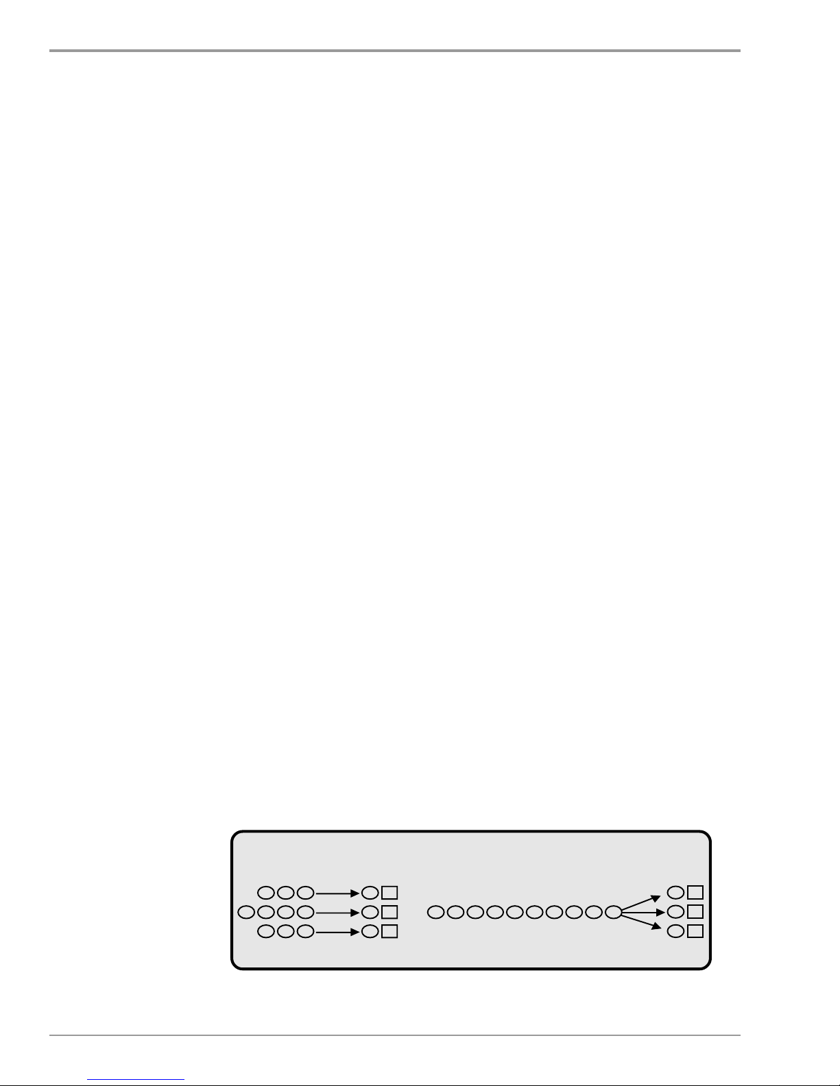
The Trunking Advantage
The advantages of trunking can be illustrated by a very simple
example. Most of us are familiar with problem of standing in line for a
bank teller or at a ticket window, as illustrated in Figure 1 below.
Queuing analysis shows that more people (customers) can be handled
with the same level of service when all servers (channels) are available
to all customers.
A. B.
Queues Clerks Single Queue Clerks
Figure 1 - Which kind of line would you prefer to stand in?
6
Page 7

1 • Things you always wanted to know about trunking…
Rules Regarding VHF and UHF Trunking in the United States
The FCC has authorized the use of “centralized” trunked systems for
VHF and UHF frequency bands
a Protected Service Area (PSA). This frequency is identified with a station
class designation of FB8 for the Repeater. While FB8 codes are used only
with trunked (YG or YW) systems, an FB8 frequency may not be used for
conventional systems.
Centralized trunking refers to trunking systems that use dedicated
(exclusive) control channels for data communication between the
mobiles and the trunked repeaters. In such systems, the mobiles
constantly monitor the control channel for channel assignment
instructions. When a group call is initiated, the trunking controller
transmits instructions telling the mobiles in the group to switch to a
voice channel assigned for that conversation. Thus, the “brains” of the
system are in the system controller at the repeater site.
where at least one frequency must have
Most trunking systems such as MPT-1327, Motorola’s Smartnet, E. F.
Johnson’s LTR. Trident’s Passport, etc are centralized systems. As they
are designed to use clear frequencies, these trunking formats are not
as well suited as SmarTrunk or as easy to license at VHF and UHF
frequencies because of the lack of exclusive channels in those bands.
To get around this problem, the FCC requires potential centralized
system operators. . . “to obtain some form of exclusivity in their
respective service areas”. This requires the operator to obtain written
permission from all other licensees within a 70 mile radius of the
proposed base station, similar to the FCC rules for telephone
interconnect in major metropolitan areas. However, due to the
frequency congestion in these bands, this requirement is extremely
difficult to meet. All other users on the proposed trunked channels and
immediately adjacent channels would have to agree to convert to trunked
operation. Since, by definition, centralized trunked systems require
exclusive channels, the other affected users would have to agree to a
simultaneous conversion of their radio systems, which would require
scrapping their conventional equipment and purchasing all new mobile
radios.
SmarTrunk Systems, Inc.
7
Page 8

CentrCentr
Centr
CentrCentr
alizaliz
aliz
alizaliz
ed vsed vs
ed vs
ed vsed vs
. Decentr. Decentr
. Decentr
. Decentr. Decentr
alizaliz
aliz
alizaliz
ed Ted T
ed T
ed Ted T
rr
unkunk
r
unk
rr
unkunk
ing Sying Sy
ing Sy
ing Sying Sy
stemsstems
stems
stemsstems
Unlike centralized trunking systems, decentralized (scan based)
systems such as SmarTrunk II do not require exclusive channels.
Because the channel selection intelligence is in the mobiles,
decentralized systems can co-exist with conventional users on the
same channels. When a call is initiated by a mobile unit, the channel
assignment is determined by the logic in the mobile, not by a controller
at the repeater site. So if the channel is busy with a conventional user
(or even a co-channel user on another system), the mobile will consider
the channel as busy and select another channel.
frequencies of a de-centralized trunked system would use the less restrictive
station class designation of either FB6 or FB2, which does not require a
Protected Service Area (PSA). FB6 is for private carrier systems such as
radio dealers that would place additional users on the system. FB2 is for
private in house systems such as a manufacturing facility that would use the
system for their own use.
Per FCC rules, all
The advantages of decentralized system can be summarized as
follows:
¨ Since they do not require exclusive channels, the onerous FCC
frequency coordination requirements described above do not apply.
¨ Decentralized trunking systems have always been “legal” for use below
800 MHz because they fully comply with the FCC requirements to
monitor the channel before transmitting and do not utilize dedicated data
channels for system control.
¨ Decentrallzed trunking is the only trunking protocol which will operate
on non-exclusive channels. This not only allows the system to operate
in the presence of conventional users on the same channel, but it also
allows a system operator to gradually convert conventional users to
trunked operation.
¨ They are more economical due to the lower cost of both the trunking
controllers and the mobile radio equipment.
¨ They require less technical training to install and maintain.
8
SmarTrunk Systems, Inc.
Page 9

SECTION
System Highlights
2
SmarTrunk II is a decentralized two way radio trunking system that is widely used both for
telephone interconnect and business dispatch applications at frequencies below 800 MHz.
First introduced in 1994, SmarTrunk II combines a proprietary digital signalling format
with existing two way radio technology—creating a communications system that is low cost, yet
provides many of the features of higher cost trunked radio systems.
Today SmarTrunk II provides local area wireless solutions to over 500,000 subscribers in
over 98 countries throughout the world. Due to its growing popularity, SmarTrunk II is sold in
partnership with international radio manufacturers such as ICOM, Kenwood, Motorola and Vertex.
Wireless Solutions Supported by SmarTrunk II
Virtually any organization which seeks to provide local area communications can benefit from SmarTrunk II
:
X
Community repeater operators can upgrade to group dispatch and
selective mobile to mobile calling to existing customers or expanding
markets.
X
Rural telephone operators can provide telephone service to individual
subscribers in remote areas without investing in the enormous cost of a
wireline or cellular infrastructure.
X
Radio dealers can offer a combination of telephone and radio dispatch
services, depending on the needs of individual customers.
X
Large industrial companies can use SmarTrunk II as a wireless PABX,
connecting all employees, in addition to supporting group calling
capabilities.
APPLICATIONS
• Small police and fire departments • Government agencies
• Public telephone systems • Mining operations
• Large industrial manufacturing facilities • Oil & gas pipeline operations
• Colleges or university campuses • Petro chemical operations/oil refineries
• Airports • Forestry and fishing fleets
• Casinos and Hotels • Hospitals
SmarTrunk Systems, Inc.
9
Page 10
System Overview
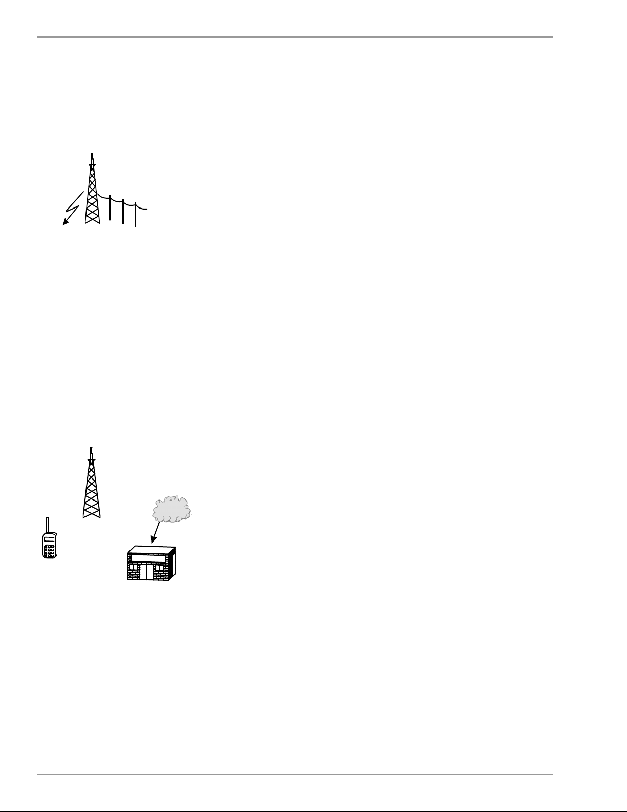
System Requirements
A SmarTrunk II radio trunking system employs low cost radio
communications equipment and SmarTrunk II technology, which is
installed at both the base station and the subscriber radios.
The base station equipment required for each channel consists of a
SmarTrunk II controller connected to a standard VHF or UHF radio
repeater. For telephone interconnect applications, the controller is
also connected directly to a standard telephone line via a RJ-11 jack.
Each channel can support one individual conversation. Therefore, a
three channel system can support
three simultaneous private
conversations.
Since SmarTrunk II is an “overlay”
system, each of the subscriber
radios must have a customized
logic board to control the radio’s
operations. SmarTrunk Systems,
Inc. manufacturers customized
logic boards for over many
different radios. Please see the
“SmarTrunk II Logic Board
Collection” (Appendix A) which
lists all the mobile and portable
radio models that are compatible
with SmarTrunk II.
10
Page 11

SECTION
Types of Calls and
Methods of Operation
Using SmarTrunk II For Radio Dispatch Applications
Mobile to Group Call
SEQUENCE OF EVENTS:
1. Mobile subscriber presses the PTT (Push To Talk) button to initiate a
group call to the subscriber’s own group. Alternatively, mobile subscriber enters desired group number followed by routing code 3 and *
on the radio keypad.
2. Mobile radio searches for an idle channel and signals the controller.
3. Base station controller acknowledges the mobile and signals all
subscriber radios that are a part of the called group.
4. Subscriber radios assigned to the called group open squelch, connection is established, and a group conversation begins.
3
5. Any subscriber in the group presses the “#” key to terminate the call,
or repeater disconnects at the expiration of the Group Activity Timer.
SPECIAL FEATURES:
¨ Automatic PTT (Push To Talk) Mode - subscribers may initiate
group calls to their own subscriber group by pressing the PTT button.
¨ Call Limit Timer - programmable call limit timer on a per user
(group) basis.
¨ Group Activity Timer - acts like a “hang timer” to retain channel for
the duration of a call.
¨ Multiple PTT Group can be selected without keypad in some radios
(see Omni Features, Section 6).
¨ Memory Speed Dial - convenient, cellular like, dialing including a re-
dial function.
¨ Clear Channel Alert - notifies the subscriber when a channel be-
comes available after the subscriber has attempted to access the
system when all channels are busy.
¨ Radio Kill - eliminates unauthorized users of the system.
SmarTrunk Systems, Inc.
¨ Conventional Mode Operation - “talk around” communications
available in certain subscriber radios.
11
Page 12

System Overview
Mobile to Mobile Private Call
SEQUENCE OF EVENTS:
1. Mobile subscriber enters desired subscriber number followed by
routing code 3 and * on the radio keypad.
2. Mobile radio searches for an idle channel and signals an available
controller.
3. Base station controller acknowledges incoming call and signals
desired subscriber radio, which responds by ringing.
4. Called subscriber answers call by pressing the * key, establishing the
connection.
5. Either subscriber presses the “#” key to terminate the call.
SPECIAL FEATURES:
¨ Call Limit Timer - programmable call limit timer on a per user basis.
¨ Channel Privacy - other users cannot interfere with or eavesdrop on
calls.
¨ Memory Speed Dial - convenient, cellular like, dialing including a re-
dial function.
¨ Clear Channel Alert - notifies the subscriber when a channel be-
comes available after the subscriber has attempted to access the
system when all channels are busy.
¨ Radio Kill - eliminates unauthorized users of the system.
¨ Conventional Mode Operation - “talk around” communications
available in certain subscriber radios.
12
Mobile Operator Call
SEQUENCE OF EVENTS:
1. Mobile subscriber enters 9 and * on the radio keypad.
2. Mobile radio searches for an idle channel and signals the controller.
3. Base station controller acknowledges incoming call and signals the
established mobile operator radio, which responds by ringing.
4. When the called party answers, the conversation begins.
5. Mobile subscriber presses the “#” key on the radio keypad to terminate the call.
SPECIAL FEATURES:
¨ Two touch dialing to access the subscriber radio that has been pro-
grammed as the mobile operator.
¨ Programmable emergency call override status.
Page 13

3 • Types of Calls and Methods of Operation
Using SmarTrunk II for Telephone Interconnect
Applications
Mobile to Telephone (Landline) Call
SEQUENCE OF EVENTS:
1. Mobile subscriber dials desired telephone number followed by routing
code 1 and * on the radio keypad.
2. Mobile radio searches for an idle channel and signals an available
controller.
3. Base station controller acknowledges incoming call and dials the
desired telephone number over the landline connected to the back of
the controller.
4. When the called party answers, the conversation begins.
5. Mobile subscriber presses the “#” key on the radio keypad to terminate the call.
SPECIAL FEATURES:
¨ Selective Toll Restriction - programmable on a per user basis to
allow or prevent long distance or toll calls.
¨ Call Limit Timer - programmable call limit timer on a per user basis.
¨ Line 1 or Line 2 Telephone access - programmable access to
telephone line 1 or line 2 on a per subscriber basis.
¨ Memory Speed Dial - convenient, cellular like, dialing including a re-
dial function.
¨ Last Number Redial - pressing * , * on the radio keypad
automatically redials a busy number.
¨ Priority Call Override - allows priority users to gain access to a
busy system.
¨ Clear Channel Alert - notifies the subscriber when a channel be-
comes available after the subscriber has attempted to access the
system when all channels are busy.
SmarTrunk Systems, Inc.
¨ Radio Kill - eliminates unauthorized users of the system.
13
Page 14
System Overview
Telephone (Landline) to Mobile Call
SEQUENCE OF EVENTS:
1. Telephone user dials the phone number of the landline connected to a
controller.
2. Controller answers the call with two beeps. Telephone user dials
PSTN
desired mobile subscriber number (1-5 digits).
3. Controller signals desired subscriber radio which responds by ringing.
4. Mobile subscriber answers call by pressing the * key on the radio
keypad, establishing the connection. Conversation begins.
5. Mobile subscriber presses the “#” key on the radio keypad to terminate the call.
SPECIAL FEATURES:
¨ Call Limit Timer - programmable call limit timer on a per user basis.
¨ Landline callers may also initiate calls to a group of mobile subscrib-
ers.
Emergency Telephone Number Call
SEQUENCE OF EVENTS:
1. Mobile subscriber enters 0 and * on the radio keypad.
2. Mobile radio searches for an idle channel and signals an available
controller.
PSTN
3. Base station controller acknowledges incoming call and dials the
established emergency telephone number over the landline connected to the back of the controller.
POLICE
SPECIAL FEATURES:
4. When the called party answers, the conversation begins.
5. Mobile subscriber presses the “#” key on the radio keypad to terminate the call.
¨ Two touch dialing to access the emergency phone number pro-
grammed by the system operator. Can be programmed for police,
fire, or any other emergency telephone number.
¨ Programmable emergency call priority override.
14
Page 15

SECTION
SmarTrunk II Controller
4
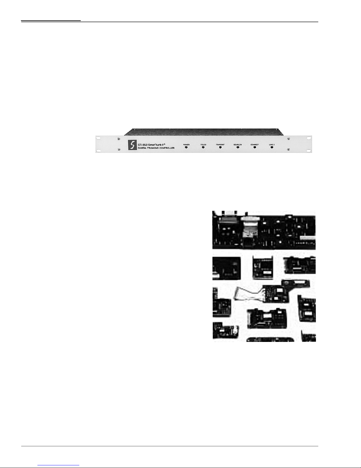
The heart of the SmarTrunk II System is the ST-853 SmarTrunk II Digital
Trunking Controller which performs all
signalling and trunking functions, including
subscriber validation and call record
accounting. The ST-853 features a
communications databus linking all the channels at a single site, an expanded memory for subscriber and call accounting records and many other new features and functions that have been
requested by SmarTrunk system operators throughout the world.
ST-853 FEATURE SUMMARY
• Subscribers per system ..................................4,096
• Call records per controller ...............................4,500
• Paging code combinations available ............... 320,000
• Communication between controllers ............... Serial databus
• Single access point for uploading ................... Yes
or downloading system data
• Programming software .................................... Menu driven PC DOS application
• Off-line programming sessions ........................ Yes
• Local transfer speed ....................................... 9600 baud
• Modem transfer speed ....................................9600 baud
• Security password for programming ................ 2 password levels, up to 8
alpha numeric characters
• Method of assigning parameters ..................... Assigned to profiles which are assigned
to subscribers to subscriber
• Direct connect without overdial for ................... Yes
incoming telephone calls
• Total number of toll restriction .........................8 restricted prefixes and 8 override
prefixes per system prefixes
SmarTrunk Systems, Inc.
15
Page 16
System Overview
Expanded Capacity
Databus Communication between Controllers
An ST-853 system can support up to 4,096 individual subscribers or
groups. In addition, most features are programmable on a per
subscriber basis, such as the mobile activity timer, telephone line
access, courtesy beep and expanded toll restriction options. Each
controller can store up to 4,500 call records. The programmable call
records feature insures only the desired types of calls are recorded.
In the subscriber database, each subscriber or group may be assigned
a different System ID. For radiotelephone applications, this provides
up to 320,000 paging code combinations for added security. This
feature also allows an ST-853 system to be programmed with
subscribers from other systems for roaming applications.
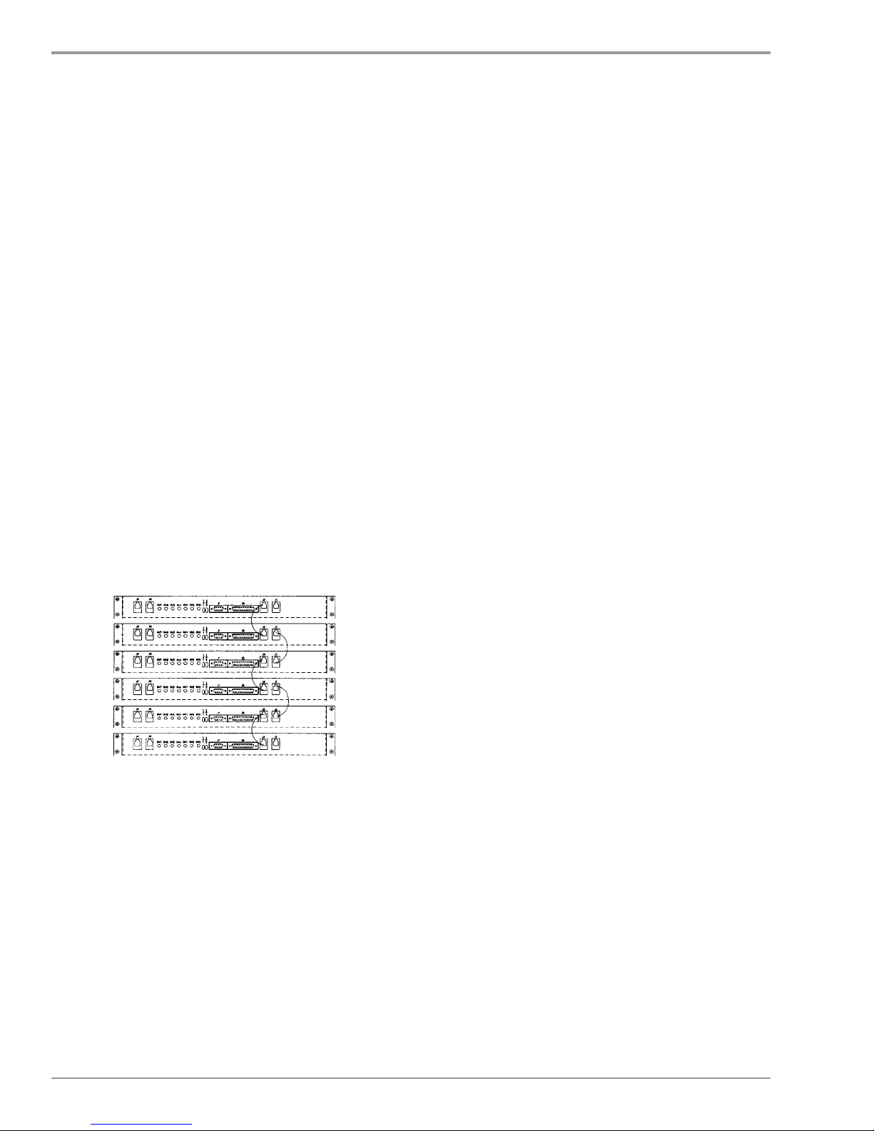
All of the ST-853 controllers at a site are connected through a serial
databus which enables the controllers to communicate. This allows the
subscriber database and all call records data to be accessed from a
single controller.
The databus is also used by the controllers to
automatically coordinate signaling when needed. If
multiple calls are placed simultaneously in an
ST-853 system, the signalling is coordinated to
prevent missed calls or split groups. If a call is
placed to an individual or group that is already
engaged in a call, the caller will receive a busy tone
indicating that a call is in progress. If the called
individual is out of range or powered off, a fast busy
tone is generated.
16
Page 17

Greater Ease of Programming
The programming software for the ST-853 is a menu driven, PC based
application which offers much more power and flexibility than the
internal software used to program the previous controller.
¨ User-friendly programming software supports off-line programming.
¨ Subscriber profiles allow the calling privileges of similar subscribers to
be changed collectively.
¨ Clone feature allows the creation of multiple subscribers.
¨ Site View displays status information about the controllers while on-line.
¨ Call records are automatically stored to disk when downloaded.
¨ Enhanced call record management marks records as new or old.
¨ Two-level expanded password scheme allows supervisor to control
system access.
¨ Database conversion utility eliminates the need to re-key an existing
ST-852 subscriber database when converting to the ST-853.
¨ External modem option offers error-free data transfer.
4 • SmarTrunk II Controller
Enhanced Telephone Interconnect Features
The ST-853 offers enhanced telephone interconnect features which can
be used to support a variety of new applications.
¨ Auto Route feature routes incoming calls to a designated subscriber
who can transfer the call to any subscriber in the system.
¨ PageBack feature allows entire group to participate in outgoing or
incoming telephone calls.
¨ Up to 8 restricted prefixes and 8 override prefixes can be selected on a
per subscriber basis.
¨ Telephone lines may be programmed to accept incoming or outing calls
on a per controller, per line basis.
¨ Voice Clears Activity Timer allows telephone users to prevent the
Mobile Activity Timer from expiring.
¨ Overdial Length and Connect on DTMF * offers faster connect times for
incoming telephone callers.
¨ Busy, Dialtone and DTMF # Disconnect features allows telephone
callers to terminate a call.
¨ Enhanced dialing procedure supports compatibility with PBXs or
nonstandard telephone switches requiring special delays or prefixes.
¨ Leading 0 Dial Click Detector reduces errors caused by line noise and
SmarTrunk Systems, Inc.
improves the ability to detect pulse overdial.
17
Page 18

System Overview
Options and Accessories
502-3501 Users Guide and Programming Software - Complete
documentation and PC-DOS programming software required for
installing, aligning and programming the ST-853 controller. One P/N
502-3501 is required for each system.
ST-910 CTCSS Decoder Option - A miniature CTCSS decoder which
may be added to the ST-853 controller to provide additional protection
from intermod or co-channel interference. Recommended for use in
the United States and other areas of high RF activity or where there is
possible interference from a distant repeater on the same channel.
ST-911 Cable Assembly Option - A 4’ long (122cm) shielded cable
assembly terminated with a DB-25 connector which mates to the ST-
853. Provides all the connections necessary between the ST-853 and
the host repeater. Note: A DB-25 connector kit (without cable) is
provided with each ST-853.
ST-956 External Modem and Cable - An external high speed modem
and interface cable used to program an ST-853 site remotely over a
telephone line (if remote access is desired). This option may be used
to install a modem at the site (only one modem required per site) or at
the local computer used for programming.
18
Page 19

SmarTrunk II Logic Boards with Omni™
SECTION
Features
The other key component of the SmarTrunk II system is a miniature
logic board which installs inside the mobile or portable radio equipment. These logic boards are custom designed for each radio and
control all the signaling and trunking functions, including scan, PTT,
and monitor. In most cases, the logic boards are easily installed by
plugging into the host radio; however, soldering may be required in
some older radios (See SmarTrunk II Logic Board Collection, Appendix A).
Highlights of the Omni feature set includes Channel Banks for multisite applications, multiple talk and receive groups, faster channel
access, positive radio kill, and greater use of the radio’s display.
5
ST-865KW4
Kenwood ‘G’ Series Radios offer
new Omni Features
ST-865M5
Motorola Professional Series Radios
offer New Omni Features
SITE #1
BANK #1
SITE #4
BANK #4
Example: Subscriber selects
bank #5 when moving to site #5.
200 km
S
BANK #3
Channel Banks on the subscriber radio, system operators may offer access
to multiple sites or even allow the radio to operate in conventional TalkAround mode. To access a remote site, the subscriber selects the Channel
Bank of the desired site. The diagram shown on the left explains a typical
Channel Banks application.
The Omni feature set is currently available for radio models from Icom,
Kenwood, Motorola, Standard, and Yaesu/Vertex (see Appendix A for
details). A summary of the Omni features is listed below:
ITE #3
ITE #5
S
BANK #5
SITE #2
BANK #2
Channel Banks
The Channel Banks feature allows
subscribers to access different sites which
may use different frequencies. Channel
Banks are accessed via the radio’s Channel
select switch i.e. Channel 1 would become
Frequency Bank 1.
By programming the frequencies of different
SmarTrunk II or conventional sites as
SmarTrunk Systems, Inc.
19
Page 20

System Overview
ST-865S4
Standard HX290 Portable Radio
offers new Omni Features
Multiple PTT Groups
In order to access a SmarTrunk II site, the subscriber
must be programmed as a valid user by the system
operator of the site. Channel Banks may also be used to
access conventional channels. When a subscriber
selects a Channel Bank programmed with conventional
channels, the radio automatically enters into the
conventional mode.
This feature is useful in cases with the system operator allows
talk-around operation among the user’s radio. Talk-around
can be used for short range direct radio-to-radio
communications without going through the trunking system.
The Multiple PTT Groups feature allows subscribers to call different
groups of subscribers simply by pressing the PTT (Push-To-Talk)
button. Previously, a subscriber could call only one group by pressing
PTT.
The system operator may program up to 16 Group Codes in the radio
logic board which may be selected by the subscriber by using one of
the spare function switches on the radio which becomes the group
switch when the radio is programmed for SmarTrunk operation. The
subscriber selects the desired group with the Group Switch. When the
subscriber presses PTT, the selected group is called. In addition, the
radio will receive calls placed to the selected group.
This feature enables subscribers who are not equipped with a DTMF
keypad to call different groups. In addition, this feature allows
subscribers to join
different PTT groups
on different days. For
example, changing
PTT groups is useful
in applications where
a subscriber regularly
ST-865IC
changes project
groups or where a
mobile radio is
frequently used by
employees who are in
different groups.
ICOM IC-F3/F4, IC-F1020/F2020 and
IC-F30/F40 offer new Omni features
20
Page 21

5 • SmarTrunk II Logic Boards with Omni Features
Multiple Receive Groups
The Multiple Receive Groups feature enables system users
to receive individual calls and/or calls placed to several
different groups. “The Block Decode Function”: In logic
boards without the Omni feature set, a subscriber can receive
only individual calls and calls placed to one group. The
receive groups are programmed in the radio logic board by
the system operator.
This feature is useful in applications where a
subscriber needs to receive any call placed
to several different groups or sub-groups.
For example, a dispatch subscriber could
receive an individual call, one or more subgroup calls and an ‘all call’ placed to all of the
subscribers in the business.
VTP-40 VTP-40
VTP-40
VTP-40 VTP-40
SmartScan™
The SmartScan feature provides faster
channel access in a busy system. During idle operation, the radio
keeps track of which channels are busy while scanning for incoming
calls. When a subscriber places a call, the radio immediately vectors
to an available channel. As a result, channel access time is reduced
considerably, especially in larger systems.
Dialed Number Display
When a subscriber dials a telephone number or Subscriber Number
using the radio keypad, the dialed number is displayed on radios
equipped with an LCD display. In addition, the current PTT Group
Code is also displayed.
Positive Radio Kill
The Positive Radio Kill feature allows a system operator to initiate an
over-the-air “kill” command from the base station. If the target is turned
on and within range, the “kill” command will disable the radio and
confirm the action in the system data base. The “killed” radio must be
returned to the dealer or system operator for re-activation. This feature
is useful to disable a specific lost or stolen radio within a group without
disabling the entire group.
Yaesu/Vertex VX-10
offers new Omni Features
SmarTrunk Systems, Inc.
21
Page 22

System Overview
Turbo SpeeDial™
Memory Speed Dial
The Turbo SpeeDial feature offers one-touch speed dial. Subscribers
may program up to four telephone or subscriber numbers which may be
dialed by pressing a single button on the keypad, either A, B, C or D.
Note: Exact features, including the number of Channel Banks
available, may vary from radio to radio. Contact factory for details.
Allows users to place calls to up to 10 frequently called groups, individuals
or telephone numbers. Dealers have the option of allowing users to
program these memory locations. Dealers may also restrict keypad calls
to memory speed dial calls.
Speed Dial calls are dialed by pressing * and the memory location.
Caller ID
When an individual call is made to a radio, the display on the radio (if so
equipped) will show the unit ID of the user who is calling. At the present
time, this feature will only be available for mobile-to-mobile calls, but not
incoming landline calls. The group ID is displayed during a group call.
This feature is functional in ST-853 stand-alone systems. A side benefit of
this feature is that it is also used as an ANI. With the optional Dispatch
Console, a radio’s individual ID can be displayed on the Dispatch Console
screen even during Group calls.
Speech Scrambler
The new 3G family of logic boards supports voice inversion encryption for
secure speech. This feature can be enabled or disabled by the user once
the call is established. This feature is presently not available for landline
calls. Secure speech can work with ST-853 (stand-alone) or ST-510 based
systems. (May not be available for all models).
22
Page 23

Beyond The Simple
SECTION
“Controller only” System
INTRODUCTION
The ST-510 is a computerized modular switch designed exclusively for use
with the SmarTrunk II™ Trunking System. The ST-510 allows system operators to offer advanced features and services. In addition to providing multisite, wide area coverage, the ST-510 offers voice prompts, voice mail, call
forwarding and many other advanced features listed below.
The ST-510 Network Switch is compatible with the ST-853 SmarTrunk II
controller and all SmarTrunk II Omni logic boards. This makes it possible
for SmarTrunk II system operators to expand their existing systems without
having to add new controllers, repeaters, or subscriber radios. The only
modification required to existing SmarTrunk II controllers is the replacement
of the controller’s firmware EPROM.
6
KEY SYSTEM FEATURES
The ST-510 allows SmarTrunk II system operators to add the following high
performance features and services. Please note that many of these features
may require optional hardware, software and/or operating firmware, as described on page 38.
* Voice Mail
* Call Forwarding to Another Radio or Telephone
* Real Time landline Call Transfer to Another Radio
* Pre-Recorded Information Service for Subscribers (Weather, Traffic,
Schedules)
* Very Detailed Usage Data Base and Billing Package
* Network Airtime Statistical Reports
* Dispatch Console
* Searchable Voice Logger
* Wide Area Multi Site Roaming
* Simplified Linking
* Remote Site Telemetry
* Late to Join and Lost Radio Rejoin Capability (3G)
* One Time Groups are Joined on One Channel (Dynamic regrouping) (3G)
* Automatic User Registration on Power On or at New Site
* Can Provide Gateway to Another Radio System (3G)
SmarTrunk Systems, Inc.
23
Page 24

System Overview
ST-510 SYSTEM COMPONENTS
The ST-510 also adds valuable features to the basic SmarTrunk II protocol:
• Multi site Roaming
• No Routing Digit required
• Sharing of PSTN lines
• Larger Call Record database
• More customer profiles available
• More Subscriber ID codes
• Local & remote system management
• Remote site telemetry late to join radio is automatically sent to group call if
call is in progress
• Lost radio can rejoin a group while call is in progress
CPU: The heart of the ST-510 is a rugged, fault tolerant industrial PC with
DSP (digital signal processing) resources. The PC runs all the software routines required for the switch control and the services supported. The switch
also assumes many functions normally supported by the SmarTrunk II controller, such as data base maintenance, subscriber validation and call record
accounting.
Switch Rack & Power Supply: The ST-510 system components are mounted
in a standard 19" rack panel with eleven slots to accommodate the switching
components plus the power supply. Additional rack panels may be added to
the system as required.
Each rack panel includes a power supply that provides the required system
voltages and supervises the overall system performance and serve as back-up
to power supplies of other racks.
ST-422 Switch Board: All system switching and interface functions are performed by the ST-422 Switch Board. The ST-422 contains a micro-controller,
an analog matrix switching structure, plus a highly versatile analog input/
output with adjustable levels for each incoming or outgoing path. The ST-422
also has an RS-232 data port for digital interconnection with any external
device.
By use of an on-board DIP switch, the ST-422 can be easily configured for
several different system functions:
24
Page 25

• ST-852/853 controller gateway
• Voice prompt/voice mail DSP gateway
• PSTN/PBX gateway
• Roaming Bus gateway
• Inter-site link gateway
• Dispatch console gateway
• Interoperability radio gateway
SYSTEM OPERATION (BRIEF EXAMPLE)
When a call request arrives at a SmarTrunk II controller, a short data packet
will be sent from the controller’s RS-232 data port to the ST-422 board which
serves as the switch gate for that controller. This packet is processed by the
main ST-510 CPU and software, which decodes all information such as subscriber number, required service, etc. Once the subscriber name is decoded,
the program will access the main database, looking for the subscriber profile
and checking if the service request is valid for that particular subscriber.
If the requested service was a mobile-to-mobile call, the system software will
search for the profile and status of the called party, checking if the party is busy
or free and if this type of call is valid for the called party. If valid, the ST-510
will send a new data packet (via Roaming Bus) to each site in the network
where the called party is authorized to roam. The ST-510 at the remote site(s)
will then direct a free SmarTrunk II controller to page the called party.
The SmarTrunk II controller will the look for the acknowledgment signal from
the called party. If the called party is out of range or his/her radio is turned off,
the main ST-510 computer will immediately transfer the caller to Voice Mail.
If the called party is within range, the main ST-510 CPU opens an audio path
from the original controller (calling party) to the second controller (called party)
in a process which requires no more than one-half second beyond the normal
SmarTrunk II signaling time. If the called party answers, the conversation
takes place as normal. If the called party does not answer within a programmed time, the calling party is directed to Voice Mail. When either party
ends the call, all resources are released and the call information is reported to
the call record account file.
SmarTrunk Systems, Inc.
25
Page 26

System Overview
SYSTEM REQUIREMENTS
Operators considering a ST-510 Network Switch should first be thoroughly
familiar with the SmarTrunk II signaling protocol and basic operation, as described in the operating manual for the
510 system operates with the SmarTrunk II protocol using the same ST-853
controllers as a conventional SmarTrunk System; however, a new firmware
EPROM is required for each controller.
Each local SmarTrunk II controller is connected to the local ST-510 switch by
two links: an RS-232 data cable and an audio link from the controller’s line 1
TELCO port to the audio port of the ST-422 board assigned to that controller.
If the system has more than one site, an ST-100 multiplexers are used to
connect to remote ST-853’s. For PSTN or PBX interconnection, the ST-510 has
a conventional line termination for an analog TELCO line (2 wire, loop start).
ST-853 Trunking Controller. The ST-
The system power supply is available in 110 or 220 VAC (50/60 Hz) versions.
FEATURES AND SERVICES PROVIDED
Note: Some features are optional. Please see page 38.
Wide Area Roaming
The ST-510 supports two roaming scenarios:
•
Single ST-510 Switch:
It is most often the case to have a single ST-510 Network Switch support
multiple repeater sites. In this case, the SmarTrunk controllers (up to 128
maximum) are linked to a central ST-510 site. Different roaming areas may be
defined which correspond to the different repeater sites.
This is the most economical scenario because only one ST-510 switch is required
to support the entire network. There must however, be a link for each repeater/
ST-853 channel at the remote site(s). For more details, refer to page 37.
26
Page 27

•
Multiple ST-510 Switches:
Larger networks may use multiple ST-510 switches, requiring only one low
speed data bus (from 4800 baud) to link the switches. As with the single
switch scenario, this service allows customers to locate any subscriber in the
entire network simply by dialing the subscriber’s number. In this scenario, the
number of audio paths (links) required in the system depends on the anticipated roaming traffic between the sites.
The definition of the roaming areas and the associated subscriber profiles are
created automatically using the comprehensive management software included
with the system.
Voice Mail
If a subscriber is unable receive a call, the ST-510 will connect the calling party
to an audio file containing the subscriber’s voice prompt messages. The system has three voice mail greetings for each of the following situations:
• Mobile is powered off or is out of range
• Mobile is in range but the subscriber does not answer the call
• All incoming calls automatically forwarded to voice mail service
After the system plays the appropriate greeting message, it will record the
caller’s message. The length of the message is programmable for each subscriber.
All subscriber messages are digitally recorded on the hard disk of the ST-510.
When a subscriber wishes to listen to his/her messages, he/she will dial 111*
from their radio and the system will play back the number of messages in
memory and will indicate the date and time of each message.
During message playback, the subscriber can command the system to request
a new message, repeat the last message, delete messages, etc., using the radio
keypad. The quantity of messages in memory for each subscriber will depend
of the hard disk capacity of the system. If necessary, a hard disk array can be
added to the system.
SmarTrunk Systems, Inc.
27
Page 28

System Overview
Call Forwarding
If a mobile subscriber is out of range or away from his radio, he may choose to
have incoming calls forwarded to another radio, a PABX extension, or to any
PSTN number. When an incoming call arrives for the subscriber, the ST-510
automatically intercepts the call and re-directs it according to the subscriber’s
instructions.
In order to program the call forwarding service, the user dials 211* from their
radio. A friendly voice prompt will guide the user to enter all required parameters, such as the telephone number or SmarTrunk extension to be called, and
how long the current parameters are to remain active (optional).
There are three ways to forward a call:
• To any PSTN number or PABX line extension
• To another radio or group of radios in the network
• To the voice mail service (do not disturb service)
Call Transfer
When a user receives an incoming call from the PBX or PSTN, the user can
transfer the call to another radio or group in the network. The external call will
remain on hold until the new radio is on line. After the transfer, the first radio
will return to standby mode while the second radio receives the call. One new
entry in the call records account will be added for each partial call.
28
Page 29

Subscriber Toll Restriction
The ST-510 maintains a full profile in memory for each user radio. One of the
fields of this profile is used for toll restriction, which can be implemented in
one of two ways:
• List the restricted numbers
• List the allowed numbers
In the first case, the system operator may enter a list of restricted numbers or
prefixes (up to 100). If the subscriber dials any of the restricted numbers or
prefixes, the system will deny access.
In the second case, the system operator enters only the allowed (valid) numbers. All other numbers will be denied access to the system.
Access to the toll restriction parameters is password protected.
Emergency Routines & Dynamic Regrouping
With the addition of the ST-510 Network Switch, and Dispatch Console, the
system operator may define a dynamic (virtual) group number for critical emergency situations.
For example, in an airport communications system, it may be necessary to
make an emergency call between all the supervisors of different forces
(firefighters, police, ambulance, traffic control, etc.). When the emergency
begins, the dispatcher will place a call to a virtual number which represents the
pre-defined emergency group. The ST-510 will then gather all the defined
group members on one free channel in all coverage areas in the network.
In order to do this, the system will automatically terminate any call which may
be in progress by the designated users so they will be able to participate in the
emergency call. The emergency call will remain on the air until terminated by
the dispatcher. In this virtual call, some PSTN or PABX resources may also be
included. If desired, the special call may be recorded for security purposes.
Subscriber Usage information
SmarTrunk Systems, Inc.
29
Page 30

System Overview
Critical Messages
A service provider may allow each subscriber to periodically check certain
usage data so that there are no surprises at the end of the billing period. By
dialing 311*, the system will dictate, by voice response, all the usage for any
radio, including details such as air time used, minutes of local or international
calls, and the amount of the subscriber’s credit balance.
If this service is active, any subscriber may also program a usage alarm so that
when a pre-defined target has been reached (e.g., air time minutes, remaining
credit balance, etc.), the system will automatically call the subscriber to report
this information.
For special applications, the ST-510 provides 90 message boxes for the system
operator to record important information of interest to users. For example, by
dialing 411* plus a message box number, a user could hear the latest highway
conditions, weather forecast, financial reports, or upcoming shift schedules If
desired, these messages could be recorded and updated by a commercial sponsor who would compensate the system operator for providing this service.
Access to these message boxes may be made through the PSTN, PABX, or
radio.
Queued Traffic (Call Manager)
In peak traffic periods, subscribers may often not be able to access a free
channel when they attempt to make a call. With the addition of a simplex or
semi-duplex radio on an extra channel, the ST-510 will add the attempted call
to a queue, so that when a channel becomes available, the user will automatically be called and given access to the free channel. This channel would only
handle call requests in the event of all normal system channels being busy the
call manager would never carry voice traffic.
A priority user analyzer module of the ST-510 software will process the queued
traffic by priority of the users. In the event of an emergency call arriving in the
queue while all channels are busy, the system automatically drops the lowest
priority and oldest active call and places the emergency call immediately.
By the use of this feature, the system loading may be increased significantly in
accordance with the queued traffic model of Erlang C.
30
Page 31

Dispatch Consoles
The dispatch console is a common PC connected directly to an ST-510 or one
or more on a network. With this software, the dispatcher can make highspeed calls, monitor calls, receive calls (radio or landline), do dynamic regrouping, call up pre-programmed emergency routines. All this activity can
be performed from the screen of the dispatch terminal to the PC’s sound card
via ethernet. Any type of call may be made from the dispatch console.
The dispatch software offers several security levels and accessibility layers for different dispatchers. For example, one dispatcher may work only with his/her fleet, while
the dispatch supervisor may work with any subscriber or group in the network.
If the system requires more than one dispatch console in one site, dispatch server
software is available which will support multiple dispatch positions on a network.
The following is an example of the dispatch screen:
Security Recording
SmarTrunk Systems, Inc.
31
Page 32

System Overview
For some security applications is it very important to keep a log of all calls into
the system. If this option is desired, an additional package is available which
includes extra DSP ports and software. Any call into the network will be recorded and a database will be created with a register of each call, including:
• Date of the call
• Time of the call
• Originating user
• Second user involved
• Call length
• Audio of the call
These records are managed by the ST-REC play back software. This software
is a database search engine which has all tools required for filtering and play
back of any recorded call. The software runs on any multimedia PC and uses a
standard telephone to listen to the recorded calls.
The audio files may be backed up using any data storage media. A special file
restore utility is included in the software package to restore archived files into
the system in order to listen to a specific call or call sequence.
Voice prompts
When an incoming landline call is received, a voice prompt will answer the call
and direct the caller to dial the desired users number. If a user forgets how to
use a particular service or feature, he/she may dial 01* which will activate an
interactive voice response system to reach the desired service.
Operator services for lost calls
If somebody wishes to call a user but has lost the users number or does not
have a DTMF radio or telephone, the call can be automatically transferred to a
radio in the network designated as the Operator. The Operator can then be
transferred to the called user. Any number in the network, including a PSTN
or PABX number or the dispatch console, may be designated as the Operator.
32
Page 33

Remote system access
All the services and features of the ST-510 Network Switch can also be accessed from the PSTN or PABX. So for example, if a users radio has a dead
battery, he or she may place an incoming call from the PSTN or any PABX
extension and program the call forwarding service. The system administrator
provides a confidential password for each subscriber to remotely access the
system.
Comprehensive billing software package
An optional billing software package is available for the ST-510 which provides
a host of different features and billing options such as variable rate schedules,
multiple billing time periods, fixed recurring charges, customized formats for
invoices and statements and prepaid billing options. Available in both English
and Spanish versions, the billing software may be run “on line” for real time
accounting of prepaid calling cards, or offline in a conventional “batch” mode.
UPGRADES TO A BASIC SMARTRUNK II SYSTEM
Over the air activation
New network users can be temporarily enabled in the database over the air.
This makes it easy to add radios to the network since they can be added to the
database at any time but only activated when the users is ready to begin
service. A five digit password assigned by the system administrator is required for over the air activation.
Automatic Routing Path
In a normal SmarTrunk II system, the user must dial a routing digit for certain
calls, e.g., 1* for a PSTN/PABX call; 3* for mobile-to-mobile, etc.
With the ST-510, routing digits are not required because the system is able to
recognize different numbering plans and automatically route each call accordingly.
SmarTrunk Systems, Inc.
33
Page 34

System Overview
Sharing PSTN Resources
Larger Call Records Database
A stand-alone SmarTrunk II system requires that PSTN/PABX lines be connected directly to specific controllers. This means that only those controllers
with lines connected can be used for PSTN/PABX calls.
When using the ST-510 Switch, PSTN/PABX lines are connected to the switch
rather than individual controllers, so that PSTN/PABX resources can be shared
by any controller in the network. It may also be possible to reduce long
distance charges by routing long distance calls to a target city through the
network.
With the ST-510, call records are stored on the hard disk of the main CPU
where they can be maintained indefinitely, depending on disk capacity. This
eliminates the need to frequently download these records from the individual
ST-852/853 controllers.
More users profiles
Because users data is stored on the hard disk of each ST-510 in the network,
the number of users profiles is virtually unlimited. The new users profiles are
also enhanced because of the many additional parameters for each users.
Larger users Capacity
A normal SmarTrunk II system is limited to 4,096 users per site. With the ST510, up to 320,000 users can be activated on the network.
34
Page 35

Local & remote management
The ST-510 includes a Windows
can be run locally on a PC at any site, or remotely. In addition to adding new
users, this software can be used to maintain and report high-level technical
information such as peak period usage, system usage by channel, system
loading by site, grade of service, balance of traffic between channels, etc.
Special routines permit the system administrator to detect potential system
problems such as low remaining disk storage area and poor communication
efficiency into the switch. This information is essential to allow system administrators to optimize system efficiency.
Late to Join
If a user is busy on another call, and a call of his group (or sub group)
originates on another channel, the system will move the “late to join” user to
the group call in progress whenever that user completes his other call.
If the user was powered off when the group call started, and powers on the
radio while the group call is still on the air, that radio will also be merged
automatically to the group call in progress.
®
based management software package which
Lost Radio Re-Join
If a user that is involved in a group call enters a “shadow” area (area of no
radio coverage), the radio of course will miss the call while the user is out of
range. Realizing this, the user can easily rejoin the group by calling the group
as the radio re-enters radio coverage area.
SmarTrunk Systems, Inc.
35
Page 36

System Overview
NETWORK INTERCONNECTION
Networking over E1/T1 link
The Figure below shows a standard method to link multiple ST-510’s using a
shared or fractional E1/T1 link. At the ST-510, there is only one data connection for the Roaming Bus and in this example, four simultaneous audio ports
that may be multiplexed by a digital MUX and inserted into the E1/T1 scheme.
In the system it is necessary to install as many audio ports as the inter site
traffic will require but only one data port for each ST-510 to be connected with
any node in the network.
36
Page 37

LINKING TO REMOTE AREAS
The ST-100N Multiplexer is used to link any remote ST-853 trunking
controller/repeater combination and the ST-510 switch. One ST-100N is
required per remote channel. The ST-100N converts data and audio to and
from the ST-853, to a signal, which can be carried by the equivalent of a 2wire voice grade audio circuit.
At the ST-510 side, ST-422 Multifunction Interface Cards provide the
gateways to the link(s) and therefore the remote ST-100N(s). The ST-100
also has remote site linking capability. Some features of the ST-100
Multiplexer are:
• Simplifies linking requirements.
• ST-853 audio and data transfer can be done over “voice grade” circuits
• Allows many linking options (leased lines, spread spectrum, microwave,
T1/E1, RF phone line extenders etc.
• Contains remote site telemetry ports (4 analog, 2 digital in, 2 digital out)
• Analog input range is between 0 and up to 12VDC (adjustable)
• Fast voice/data switching
• Voice over iP capability
REPEATER
SmarTrunk Systems, Inc.
ST-853
REMOTE
SITE
S
T
1
0
0
R
A
FXO/FXS 2W LINE
S
T
4
2
2
LOCAL
SITE
ST-510
37
Page 38

System Overview
Many of the features and services of the ST-510 Network Switch require optional
hardware, software, and/or operating firmware. In most cases, these features are
customized to meet the exact requirements of the specific application.
The features below are options that can be added to an ST-510.
• Call Recording for Security Applications: This option provides software in
the ST-510 which adds the features of a digital recording system to record and store
audio passing through the switch. Calls are recorded in a compressed format. All
channels into the switch are recorded simultaneously. The storage capacity of the
hard disk of the main computer is sufficient to save 711 hours of continuous audio.
The oldest calls will be erased when the disk is full, saving the most recent 600 hours
of calls. This feature includes the ST-REC software designed to search and play back
only the calls that the system operator wishes to hear.
OPTIONAL FEATURES
• ST-500 Dispatch Console: This optional software may be installed in any PC,
directly connected to the ST-510 or several PC’s on a network. The system operator
or any user can do fast fleet dispatch, look at fleet status on line, enable an emergency call, assign aliases, and many more functions. One ST-510 can support as
many consoles as necessary.
• Emergency routines: Emergency regrouping routines can be pre-programmed
as an overriding control feature for the entire system. When enabled, they will free
up channels throughout the network and regroup all subscribers on a unique simulcast call covering all sites in the network. This feature can be accessed from the
dispatch console or a subscriber radio that is properly programmed.
• Statistic and supervisory remote software: A complement of the standard
management software, this optional package provides system performance information to the system administrator about system loading, traffic balance between channels, time duration of calls, ranking by use, grade of service for network node, and
much more.
• Dynamic Regrouping: Allows a dispatcher or system administrator to establish
and control dynamic virtual groups, which can be rearranged from any console in the
system. A dynamic group can be composed of up to 10 different groups or individual
subscribers.
• DID Service: If analog trunk lines are available, the SmarTrunk Network can offer
Direct Inward Dialing, allowing each subscriber radio to be addressed as a common
PABX extension.
38
Page 39

Frequently Asked Questions
Q. What is SmarTrunk II?
The SmarTrunk II Digital Trunking System is a reasonably priced, wireless
A
communications system which supports group dispatch, individual selective
calling and telephone interconnect applications. It is widely used for applications
below 800 MHz, with over 6,000 systems and 500,000 subscribers in over 98
counties worldwide. By relying on low cost, conventional radio equipment and
add-on logic boards, SmarTrunk II is able to offer many advanced features
typically found in much higher cost systems.
Q. How does SmarTrunk II differ from other trunking formats?
The most recent FCC interpretation of “trunking” found in the Part 88 rules uses
A
the word “centralized” to described a trunking system which utilizes a dedicated
control channel to provide mobile control. Since the SmarTrunk system does not
utilize a dedicated control channel, we have chosen to call SmarTrunk II a
“decentralized” or “Scan-Based” system.
SECTION
7
Because there is no central controller required, SmarTrunk II is generally much
less expensive and easier to license than centralized trunking systems.
Q. What is a “Scan Based” system?
Unlike centralized systems, scan based systems do not require exclusive RF
A
channels. The channel selection intelligence is located in the mobiles. When a
subscriber initiates a call, the mobile unit searches for a clear channel based on
the absence of either system CTCSS tone or carrier. When a clear channel is
located, the mobile unit places a request for service. After validating the
subscriber’s ID, the channel controller completes the connection and provides a
talk path for the duration of the call.
Q. How are incoming calls processed?
When the mobile unit is in an idle condition, the receive audio and the PTT
A
functions are disabled. During this time the mobile is scanning for a system “call
collect” tone. When the call collect tone is detected, the mobiles stops scanning
and listen for it’s correct digital data pack. When the correct data pack is
detected, the receive audio and the PTT function is enabled and normal radio
operation begins. All unadressed radio’s resume scanning . At the end of the
call the repeater disconnects and the mobiles that were communicating resume
scanning.
SmarTrunk Systems, Inc.
39
39
Page 40

System Overview
Q. What type of signalling format does the SmarTrunk system use?
SmarTrunk II is a proprietary BPSK digital signalling format which is not compatible
A
with any other trunking or signalling protocols. Over the air ID’s are encripted to
discourage piracy. As such, it is highly immune to “hackers” and unauthorized
system users.
Although proprietary, SmarTrunk II is available for a wide range of radio models from
ten different radio manufacturers. Therefore, unlike some other trunking formats,
you are not “locked in” to a single source for radio infrastructure or subscriber
equipment.
Q. What is the average connect time for SmarTrunk calls?
The initial connect time is typically one to two seconds, depending on the type of call
A
requested, the number of channels in the system, and the channel availability at the
time of request. Once a channel is acquired, it is held for the duration of the
conversation; therefore, subsequent PTT’s are instantaneous.
Q. What base station equipment is required for a SmarTrunk system?
A typical SmarTrunk channel would consist of the following items:
A
¨ One SmarTrunk Model ST-853 Station Controller per repeater.
¨ Any VHF of UHF radio repeater per channel - Alinco, Icom, Kenwood, Kyodo,
Motorola, Standard, Tait, Yaesu/Vertex or other suitable station repeater.
¨ Antenna system - duplexer or combiner depending on the number of SmarTrunk
channels. Coaxial cable and connectors as required.
¨ A power supply for the radio repeaters and the SmarTrunk controllers.
Each controller in the SmarTrunk system is capable of providing all system services.
There is one SmarTrunk ST-853 controller required for each repeater in the system,
up to a maximum of 16 channels per system.
Q. What modem do you recommend I use for my SmarTrunk system?
An external modem is required to remotely program the ST-853 controllers via a
A
phone line. We recommend either our ST-913 External Modem (which is a
complete kit of all items required). SmarTrunk does not support all makes and
models of modems. Please call the SmarTrunk factory if you have any questions.
40
Page 41

7 • Frequently Asked Questions
Q. What mobile and portable radios are available for SmarTrunk
operation?
SmarTrunk supports over 50 makes and models of portable and mobile radios from
A
ten different manufacturers. See Appendix A for a complete listing of radios
supported by SmarTrunk II.
Q. What equipment is required to program the SmarTrunk II controllers
and logic boards?
The ST-853 SmarTrunk II controller is programmed with a PC compatible computer,
A
using a DOS program available from SmarTrunk. (Mobile radio logic boards are
programmed from the radio keypad or, in some cases, from a PC in conjunction
with the radio programming software).
Q. Is any additional equipment required to support telephone
interconnect?
No. All ST-853 controllers come fully equipped with telephone interconnect
A
capability. Each controller has two standard RJ-11 telephone jacks which accept
normal two wire, loop start lines from a PBX or the PSTN.
Q. Do all SmarTrunk II subscriber radios require a DTMF keypad?
No. Group dispatch calls are placed simply by pressing PTT (Push To Talk).
A
Subscribers who place or receive only group dispatch calls do not need a keypad.
Only those users placing telephone calls or private calls to other users require a
radio equipped with a keypad.
Q. Is it possible to connect a mobile radio to a standard telephone
instrument or a fax machine?
Yes. A subscriber radio may be connected to a fax machine, a standard telephone
A
instrument and even a computer modem if it is equipped with the ST-869 Radio/
Telephone Interface Module. The ST-869 includes both the SmarTrunk II logic board
and telephone interface circuitry providing talk battery, ring voltage and an RJ-11
phone jack. (A full-duplex subscriber radio is required when supporting modem
applications.)
SmarTrunk Systems, Inc.
41
Page 42

System Overview
Q. Can the SmarTrunk system operate in a co-channel environment?
Yes. In fact, this is one of the key advantages of the SmarTrunk II protocol. Due to
A
the de-centralized system control concept, the system utilizes a distributed control
method which is available on any channel in the system. This eliminates the need
for a dedicated control channel to manage the system. The mobile radios perform
the required “channel monitor prior to transmit” responsibility which is performed
automatically by the SmarTrunk logic boards. The SmarTrunk channel monitor
function may be programmed in the radio to detect either Carrier or CTCSS Tone
as the channel busy status.
Q. How many users per channel can the SmarTrunk system
accommodate?
There are many factors which determine the practical number of users per channel
A
in any trunking system, including: 1) The type of operation on the system, i.e.,
dispatch, mobile to mobile, mobile telephone; 2) The level of service desired; and
3) The number of channels in the system. For example, based on our Traffic
Analysis Study and input from our system operators, the following loading figures
may apply for a typical five channel system:
System: ..................................................... Five SmarTrunk II channels.
Grade of Service: ....................................... 10% (One in ten call attempts will
receive a busy)
Approximate number of radios per channel:
Operation: ................................................. 100% mobile telephone = 25 to 40
Operation: ................................................. 50% mobile telephone,
50% dispatch = 50 to 75
Operation: ................................................. 100% dispatch = 100
Q. Who provides product warranty for SmarTrunk equipment?
SmarTrunk products are warranted by SmarTrunk Systems, Inc., against defects in
A
materials and workmanship for a period of two years from the date of shipment.
This warranty policy is honored by the SmarTrunk factory. Radios and other system
equipment are warranted by the respective manufacturers.
Q. Is SmarTrunk factory training available?
Yes, we schedule factory technical training seminars ata various times. Contact our
A
sales department for specific information, or refer to our Internet Web Page for the
current seminar schedule (www.smartrunk.com).
42
Page 43

Appendices
Appendix A........... SmarTrunk II Logic Board Compatibility Chart
Appendix B .......... SmarTrunk System Application Notes (SANS)
Appendix C .......... SmarTrunk vs. LTR
Appendix D .......... Simplified Customer Numbering Plan
Appendix E .......... ST-510 Wide Area Network Switch
SmarTrunk Systems, Inc.
43
Page 44

System Overview
Appendix A - The SmarTrunk II Logic Board Collection
The SmarTrunk II digital trunking system is compatible with a wide variety of two-way
radios made by the industry’s leading manufacturers. The following table lists the model numbers
of each of the radios compatible with SmarTrunk II. Also described are key features which
apply to each radio in addition to the model number of the SmarTrunk II logic board required for
operation.
Column Heading Descriptions
Compatible Radio Model No.: The manufacturer and model number of the radio described.
FCC: Indicates which radios have been FCC type accepted for sale in the United States.
* Frequency Band (MHz): The approximate frequency range of available configurations.
Radio Duplex: Indicates whether the radio is capable of half duplex or full duplex operation.
* Number of Channels: The maximum number of channels available for SmarTrunk operation.
* Note: Contact the radio manufacturer for specific details.
Feature Set:
¨ Basic - The original SmarTrunk II feature set
which includes automatic channel acquisition,
PTT dispatch, and call privacy. Radios with
keypads also support selective calling and
telephone interconnect. Refer to a SmarTrunk II
brochure for complete details.
¨ Basic / Banks - Includes the “Basic” feature set
listed above. In addition, users may select
different banks of RF frequencies, allowing the
radio to be used in different SmarTrunk II
systems (i.e. supports multi-system
applications). The number of different RF banks
which may be selected is also shown.
¨ Omni / Banks - Includes the “Basic / Banks”
feature set listed above in addition to the Omni™
feature set, offering multiple PTT groups, multiple
receive groups, SmartScan, and more. The
number of different RF banks which may be
selected is also shown. Refer to the “Omni
Feature Set New Product Bulletin” for further
information.
¨ Enhanced Omni / Banks - Includes the “Omni /
Banks” feature set listed above. Other features
include PC programming software, enhanced
flexibility for multi-system applications, and
selective/interconnect calling for radios without
keypads.
Conventional Operation:
¨ None - Conventional operation is not supported.
¨ Limited - Conventional operation is possible using
the trunked channels of the SmarTrunk II system
only.
¨ Flexible Operation - Users may select different
conventional channels outside of the SmarTrunk II
system.
Install Ease:
A rating of how easy it is to install the SmarTrunk II
logic board in the radio. An estimate of the time
required for an experienced technician to perform the
installation is also listed.
¶ Simple plug-in. Estimated installation time:
3-5 minutes.
· Partial plug-in. Estimated installation time:
5-10 minutes.
¸ Full solder. Estimated installation time:
10-30 minutes.
¹ Full solder with modifications. Estimated
installation time: 20-45 minutes.
º Full solder with modifications and additional
parts required. Estimated installation time:
30-60 minutes.
SmarTrunk Model No.:
The model number of the SmarTrunk II logic board
compatible with the radio described.
44
Page 45

PORTABLE RADIOS
Compatible FCC Frequency Radio No.Of Feature Conven. Install SmarTrunk
Radio Model No. Band Duplex Chan. Set Oper. Ease Model No.
(MHz)
Alinco DJ-195 No 136-174 Half 32 Basic/ 2 Banks Flexible 1 EJ-38D
400-470
Alinco DJ-196 No 136-174 Half 40 Omni/2 Banks Flexible 1 EJ-39D
400-470
4
4
Alinco DJ-680
No
Tx 150-174 Full 40 Basic / 4 Banks Flexible 1 ST-865AL3
(Cross Band) Rx 450-470
Icom IC-F3/S Yes 136-150 Half 32 Enhanced Omni Flexible 1 ST-865IC
Yes 146-174 2 Banks
(Icom p/n UT-105)
Icom IC-F4/S Yes 400-430 Half 32 Enhanced Omni Flexible 1 ST-865IC
Yes 440-470 2 Banks
(Icom p/n UT-105)
Yes 470-50
Yes
Yes
Yes
Yes
Yes
Yes
Yes
Yes
1
136-150 Half 40 Enhanced Omni Flexible 1 ST-865IC
1
146-174 2 or 5 Banks
1
136-150 Half 40 Enhanced Omni Flexible 1 ST-865IC
1
146-174 2 or 5 Banks
1
400-430 Half 40 Enhanced Omni Flexible 1 ST-865IC
1
440-470 2 or 5 Banks
1
470-500
1
490-512
1
400-430 Half 40 Enhanced Omni Flexible 1 ST-865IC
1
440-470 2 or 5 Banks
1
470-500
1
490-512
2
2
2
2
(Icom p/n UT-105)
(Icom p/n UT-105)
(Icom p/n UT-105)
(Icom p/n UT-105)
Icom F3GT Ye s
Icom F3GS Yes
Icom IC-F4GT Yes
Icom IC-F4GS Yes
Icom IC-F30/LT No 136-150 Half 96 Enhanced Omni Flexible 1 ST-865IC
Yes 146-174 6 Banks
(Icom p/n UT-105)
Icom IC-F40/LT No 400-430 Half 96 Enhanced Omni Flexible 1 ST-865IC
Yes 440-470 6 Banks
(Icom p/n UT-105)
Kenwood TK-270/278 Yes 136-150 Half 16 Basic Flexible 3 ST-865KW2
Kenwood TK-370/378 Yes 403-430 Half 16 Basic Flexible 3 ST-865KW2
Kenwood TK-260G Yes 136-150 Half 128 Enhanced Flexible 1 ST-865KW4
Kenwood TK-270G/ Yes 136-150 Half 128 Enhanced Flexible 1 ST-865KW4
278G 150-174 Omni 16 Banks
Kenwood TK-360G Yes 403-430 Half 128 Enhanced Flexible 1 ST-865KW4
Kenwood TK-370G Yes 403-430 Half 128 Enhanced Flexible 1 ST-865KW4
Kenwood TK-378G No 400-420 Half 128 Enhanced Flexible 1 ST-865KW4
See notes next page. Specifications and descriptions are based on the information available at the time of publication
and are subject to change without notice. Radio specifications should be verified with the radio dealer or manufacturer
at the time of purchase.
SmarTrunk Systems, Inc.
150-174
450-470
150-174 Omni 8 Banks
450-512 Omni 8 Banks
450-470 Omni 16 Banks
470-490
490-512
450-470 Omni 16 Banks
45
Page 46

Appendix A • SmarTrunk II Logic Board Collection
PORTABLE RADIOS (continued)
Compatible FCC Frequency Radio No.Of Feature Conven. Install SmarTrunk
Radio Model No. Band Duplex Chan. Set Oper. Ease Model No.
(MHz)
Motorola GP-68 No 150-174 Half 16 Basic Flexible 1 ST-865M3
403-520
Motorola P1225 Yes 150-174 Half 64 Enhanced Flexible 1 ST-865M4
450-470 Omni 16 Banks
Motorola GP-300 Yes 136-174 Half 16 Basic / 8 Banks Flexible 5 ST-865M
403-520
Motorola GP-350 Yes 146-174 Half 16 Basic / 8 Banks Flexible 5 ST-865M
438-470
Motorola Pro3150/ Yes 136-174 Half 64 Enhanced Flexible 1 ST-865M6
CT250/CT450/P040/ 400-520 Omni 16 Banks
P080/GP308/GP88S
Motorola Pro5150/7150 Yes 136-174 Half 64 Enhanced Flexible 1 ST-865M5
HT750/1250/GP140/ 400-520 Omni 16 Banks
GP328/338
Standard Yes 138-174 Half 16 Basic Limited 2 ST-865S2
HX-240/242/260 (HX-240) 330-470
Standard HX-270 No 138-174 Half 32 Basic Flexible 3 ST-865S3
330-470
Standard HX-290 No 138-174 Half 100 Omni / 1 Bank Flexible 1 ST-865S4
330-470
Yaesu/Vertex VX-10 Yes 134-174 Half 102 Omni / 9 Banks Flexible 1 VTP-40
400-512
Yaesu/Vertex VX-210 Yes 134-174 Half 32 Enhanced Flexible 1 VTP-50
400-512 Omni/2 banks
Yaesu/Vertex VX-400 Yes 134-174 Half 32 Enhanced Flexible 1 VTP-50
400-512 Omni/2 banks
Yaesu/Vertex VX-500 Yes 134-174 Half 32 Basic / 2 Banks Flexible 3 VTP-20
410-512
Yaesu/Vertex VX-800 Yes 134-174 Half 32 Enhanced Flexible 1 VTP-50
400-512 Omni/2 banks
Notes:
1
FCC for IC-F3GT/F3GS/F4GT/F4GS is available only for narrow band.
2
2 banks of 16 channels each or 5 banks of 8 channels each.
3
160 or 256 channels requires Option board (EX-1764).
4
OEM Logic Boards available only through radio manufacturers.
4
4
4
4
4
Specifications and descriptions are based on the information available at the time of publication and are subject to
change without notice. Radio specifications should be verified with the radio dealer or manufacturer at the time of
purchase.
Page 47

MOBILE RADIOS
Compatible FCC Frequency Radio No.Of Feature Conven. Install SmarTrunk
Radio Model No. Band Duplex Chan. Set Oper. Ease Model No.
(MHz)
Alinco DR-130 No 136-174 Half 16 Basic Limited 3 ST-868-02
Alinco DR-135 No 136-174 Half 100 Omni/54 Banks Flexible 1 EJ-39D
400-470
Alinco DR-430 No 400-470 Half 16 Basic Limited 3 ST-868-02
Alinco DR-605 No 138-174 Full 16 Basic Limited 1 ST-868-07
(Cross Band) 420-470
Icom IC-F310 No 136-155 Half 32 Enhanced Omni Flexible 1 ST-865IC
No 146-174 2 Banks
(Icom p/n UT-105)
Icom IC-F310S No 136-155 Half 8 Enhanced Omni Flexible 1 ST-865IC
No 146-174 2 Banks
(Icom p/n UT-105)
Icom IC-F320 Yes 136-155 Half 32 Enhanced Omni Flexible 1 ST-865IC
Yes 146-174 2 Banks
(Icom p/n UT-105)
Icom IC-F320S Yes 136-155 Half 8 Enhanced Omni Flexible 1 ST-865IC
Yes 146-174 2 Banks
(Icom p/n UT-105)
Icom IC-F410 No 400-430 Half 32 Enhanced Omni Flexible 1 ST-865IC
No 440-470 2 Banks
(Icom p/n UT-105)
No 470-490
No 490-520
1
Icom IC-F410S No 400-430 Half 8 Enhanced Omni Flexible 1 ST-865IC
No 440-470 2 or 10
3
Banks (Icom p/n UT-105)
Icom IC-F420 Yes 400-430 Half 32 Enhanced Omni Flexible 1 ST-865IC
Yes 440-470 2 Banks
(Icom p/n UT-105)
Yes 450-470
Yes 470-490
Yes 490-512
Icom IC-F420S Yes 440-470 Half 8 Enhanced Omni Flexible 1 ST-865IC
Yes 470490 2 Banks
(Icom p/n UT-105)
Yes 490-512
Icom IC-F1010/1020 Yes 146-174 Half 32 or Enhanced Omni Flexible 1 ST-865IC
160
3
2 or 103 Banks (Icom p/n UT-105)
Icom IC-F2010/2020 No 400-430 Half 32 or Enhanced Omni Flexible 1 ST-865IC
No 440-490 16032 or 103 Banks (Icom p/n UT-105)
Yes 450-470
Icom IC-F1610 No 136-155 Half 128 or Enhanced Omni Flexible 1 ST-865IC
No 146-174 2563up to 8 or 163 Banks (Icom p/n UT-105)
Icom IC-F2610 No 400-430 Half 128 or Enhanced Omni Flexible 1 ST-865IC
No 440-490 2563up to 8 or 163 Banks (Icom p/n UT-105)
Kenwood TK-760/768 Yes 136-156 Half 16 Basic Flexible 3 ST-865KW2
148-174 with ST-908
Kenwood TK-860/868 Yes 406-430 Half 16 Basic Flexible 3 ST-865KW2
450-476 with ST-908
470-496
488-512
Kenwood TK-760G/ Yes 136-162 Half 128 Enhanced Flexible 1 ST-865KW4
768G 148-174 Omni 16 Banks with ST-909
See notes next page. Specifications and descriptions are based on the information available at the time of publication and are subject
to change without notice. Radio specifications should be verified with the radio dealer or manufacturer at the time of purchase.
Page 48

Appendix A • SmarTrunk II Logic Board Collection
MOBILE RADIOS (Continued)
Compatible FCC Frequency Radio No.Of Feature Conven. Install SmarTrunk
Radio Model No. Band Duplex Chan. Set Oper. Ease Model No.
(MHz)
Kenwood TK-762G Yes 136-162 Half 128 Enhanced Flexible 1 ST-865KW4
148-174 Omni 8 Banks with ST-909
Kenwood TK-860G Yes 400-430 Half 128 Enhanced Flexible 1 ST-865KW4
450-490 Omni 16 Banks with ST-909
485-512
Kenwood TK-862G Yes 400-430 Half 128 Enhanced Flexible 1 ST-865KW4
450-490 Omni 8 Banks with ST-909
485-512
Kenwood TK-868G No 400-430 Half 128 Enhanced Flexible 1 ST-865KW4
450-490 Omni 16 Banks with ST-909
Motorola SM-50 Yes 150-170 Half 2 Basic Flexible 1 ST-868M50
450-470
Motorola SM-120 Yes 150-170 Half 16 Basic Flexible 1 ST-868M50
450-470
Motorola M-216 Yes 136-174 Half 16 Basic Limited 3 ST-868-05
403-520
Motorola GM-300 Yes 136-174 Half 16 Basic Limited 3 ST-868-05
403-520
Motorola GM-350 No 136-174 Half 16 Basic Limited 1 ST-868M350
403-470
Motorola M1225 Yes 150-174 Half 64 Enhanced Omni Flexible 1 ST-865M4
450-474 16 Banks
Motorola Pro3100/ Yes 136-174 Half 64 Enhanced Flexible 1 ST-865M5
2
5100/7100/CDM750/ 400-520 Omni 16 Banks
1250/1550/GM338
Ranger SM-1630-US Yes 406-512 Full 16 Basic Limited 3 ST-868-04
Ranger SM-1645-HS Yes 136-174 Full 16 Basic Limited 3 ST-868-04
Standard GX-1608 No 138-170 Half 16 Basic Flexible 1 ST-868SM
400-470
Supercom SC-1468 No 30-512 Full 16 Basic Limited 3 ST-868-04
Tait T-2000 Series Yes 66-470 Half 100 Basic Limited 5 ST-868-05
Telemobile TM-MDT25 Yes 66-520 Full 32 Basic Limited 3 ST-868-04
Yaesu/Vertex FTL-2011 Yes 135-174 Half 24 Basic Limited 3 ST-868-01
Yaesu/Vertex FTL-7011 Yes 400-430 Half 24 Basic Limited 3 ST-868-01
450-512
Notes:
1
OEM Logic Boards available only through radio manufacturers.
2
Under development. Contact factory for availability.
3
160 or 256 channels requires Option board (EX-1764).
4
5 banks of 16 channels each plus 20 conventional channels.
Specifications and descriptions are based on the information available at the time of publication and are subject to
change without notice. Radio specifications should be verified with the radio dealer or manufacturer at the time of purchase.
Page 49

System Overview
The ST-869 Radio/Telephone interface allows a standard telephone, fax machine, or modem to be used
within a SmarTrunk II system. Telephone instruments are connected to the ST-869 through an RJ-11 interface.
The Voice Operated Transmission (VOX) circuitry of the ST-869 supports telephone and fax machine operation
using a half duplex radio. Full duplex configurations are required for modem operation. Conventional operation,
channel banks, and the Omni feature set are not supported by the ST-869.
RADIOS COMPATIBLE WITH THE ST-869 RADIO/TELEPHONE INTERFACE
Compatible FCC Frequency Radio No.Of Install SmarTrunk
Radio Model No. Band Duplex Chan. Ease Model No.
(MHz)
Alinco DR-108 No 136-174 Half 16 3 ST-869-02
Alinco DR-130 No 136-174 Half 16 3 ST-869-02
Alinco DR-430 No 400-470 Half 16 3 ST-869-02
Alinco DR-605 (Cross Band) No 138-174 Full 16 3 ST-869-07
420-470
Motorola GM-300 Yes 136-174 Half 16 3 ST-869-05
403-520 Full*
Motorola GM-350 Yes 136-174 Half 16 3 ST-869-05
(Requires application note #1009) 403-520 Full*
Motorola M-216 Yes 136-174 Half 16 3 ST-869-05
403-520
Ranger SM-1645-HS Yes 136-174 Full 16 3 ST-869-04
Seiki 9200 Series No VHF, UHF Full 16 3 ST-869-04
Supercom SC-1468 No 30-88 Full 16 3 ST-869-04
136-174
215-245
300-512
Telemobile TM-MDT25 Yes 66-88 Full 32 3 ST-869-04
136-520
Yaesu/Vertex FTL-2011 Yes 135-174 Half 24 3 ST-869-01
Yaesu/Vertex FTL-7011 Yes 400-430 Half 24 3 ST-869-01
450-512
*Requires two radios, one used for continuous transmit and the other for continuous receive. Contact
SmarTrunk Systems, Inc. to request System Application Note #1009 which explains this full duplex
application.
Specifications and descriptions are based on the information available at the time of publication and are subject to change without notice.
Radio specifications should be verified with the radio dealer or manufacturer at the time of purchase.
49
Page 50

System Overview
Appendix B - SmarTrunk System Application Notes
As part of our on going effort to respond to the individual needs of our customers,
SmarTrunk Systems has developed System Application Notes (SAN’s) to support specialized
systemconfigurations. SAN’s may be obtained from the SmarTrunk sales department, your
SmarTrunk Master Distributor or from our Internet website at www.smartrunk.com.
Cross-Connecting a SmarTrunk II Controller with a
Conventional Tone Panel
SAN’s #1002 and 1007 explain how to install a SmarTrunk controller in
parallel with a CTCSS repeater panel. This configuration allows both
conventional radios and SmarTrunk II radios to share the same
repeater and is ideal for migration purposes or for mixed systems.
Request SAN #1002 for the ST-852 controller or SAN #1007 for the ST853 controller.
When the SmarTrunk II controller and tone panel are cross-connected,
conventional users are blocked from the repeater when a SmarTrunk II
conversation is taking place. When a conventional conversation is
taking place, the SmarTrunk II users are blocked from that repeater and
will automatically scan to the next repeater when making a call. Please
note that this application requires ST-852 version 3.51 firmware or the
ST-853.
Adding a CTCSS Decoder to a SmarTrunk II Controller
Also available is information about the ST-910 CTCSS Option Kit,
which is used to support tone squelch operation during a standard
SmarTrunk II conversation. This option is useful in systems
susceptible to co-channel noise.
Normally, once a SmarTrunk II call has been initiated by a valid user,
the ST-853 controller switches the repeater to open carrier squelch
operator. This means the repeater will re-transmit any signal it receives
throughout the SmarTrunk II conversation. By installing the ST-910
CTCSS Option kit, the repeater will only re-transmit the signal if it has
the correct CTCSS tone, which can be programmed in the SmarTrunk II
subscriber radios.
The ST-910 CTCSS Option kit, which includes a tone board, can be
ordered through SmarTrunk distribution. In lieu of ordering the ST-910
kit addition, System Application Note #1001 may be used to install a
generic CTCSS tone board to support this same option. Please note
that the CTCSS option relies on the CTCSS features of the subscriber
radio. Since not all SmarTrunk II compatible radios support this
feature, please refer to the installation documents for more information.
50
Page 51

System Overview
Traffic Analysis for SmarTrunk II Systems
SAN #1006 presents charts, theory and analysis to help SmarTrunk II
system operators analyze the trade-offs between the number of users,
the number of channels and the percent of time a user will receive a
busy signal. Examples are provided to aid in understanding how to use
the charts. Also provided is a brief summary of the telephone traffic
theory (queuing theory) used to develop the charts.
SmarTrunk Systems, Inc.
51
Page 52

Appendix C - SmarTrunk vs. LTR
Because of its system security, flexibility, and low cost, the SmarTrunk II Digital Trunking
System has become the world leader for trunked radio applications at VHF and UHF frequencies.
®
But in the Americas, customers often ask how SmarTrunk II compares with LTR
Radio), which has been popular for use at 800 MHz for many years. This section presents a
comparison of the two systems, with an overview of the advantages and disadvantages of each
format.
A Difference in Channel Management
Perhaps the largest difference between LTR and SmarTrunk II is the
way that the radios are assigned a channel when a call is initiated. In
an LTR system, each mobile is managed by a home channel which
sends a continuous, sub audible signal during all conversations.
When a user initiates a call, the radio selects a channel based upon
the information it receives from its home channel controller.
(Logic Trunked
Each time the PTT switch is pressed, the system must acquire a new
channel. And if all channels should become busy in the middle of a
conversation, the users are forced to wait until a channel becomes
available. This mode of operation is referred to as “transmission
trunking”.
In contrast, SmarTrunk II uses a mobile scan based protocol where the
mobiles, not the controller, select which channel to use. When a
SmarTrunk II user initiates a call, the radio scans for an available
channel and sends a digital datapack to the controller. The controller
then sends a datapack to all of the mobiles in the system and the
appropriate mobiles respond by answering the call. At that point, the
conversation takes place on the same channel until a programmable
hang timer expires or one of the users sends a disconnect signal.
Although the initial channel access time is slightly longer, once a
channel is acquired, it is held for the duration of the conversation. This
means that subsequent PTT’s are instantaneous for the balance of the
exchange. This is known as “message” or “conversation” trunking.
®
LTR is a registered trademark of Transcrypt International, Inc.
SmarTrunk Systems, Inc.
52
Page 53

System Overview
Operating in a Crowded VHF and UHF Environment
In an LTR system, the subscriber radio must receive instructions from
its home channel before it can initiate a call. As a result, any home
channels must be assigned to clear channels. Otherwise, whenever a
co-channel user is on the air, all radios assigned to that home channel
will be unable to receive instructions and, consequently, unable to
initiate or receive calls of any kind.
Since the VHF and UHF spectrum is heavily populated in many
countries, obtaining a clear channel may not be an option. With
SmarTrunk II, all of the channels in the system may be shared with cochannel users since all the mobiles in the system automatically
monitor for a foreign carrier before selecting a channel. As a result,
SmarTrunk II is much better equipped to operate in a crowded RF
environment than LTR.
System Security Considerations
One of the primary concerns of system operators is maintaining system
security against hackers, pirates, and other unauthorized users. LTR
relies on a sub-audible data stream that is easily monitored and
duplicated. Many radio service monitors have the ability to read LTR
codes over the air, so that an unscrupulous dealer can easily determine
valid LTR codes. Once the LTR codes are determined, unauthorized
radios can be easily programmed and loaded on a system without the
knowledge or consent of the system operator.
By comparison, SmarTrunk II employs a highly encrypted, in-band
proprietary digital data burst which is immune to hackers and pirates.
As a “closed” system which can be accessed only by authorized users,
SmarTrunk II provides the system operator very high security against
non-paying customers and other unauthorized users. And if a radio
should ever become lost or stolen, it can be remotely disabled without
affecting the rest of the group or fleet.
SmarTrunk Systems, Inc.
53
Page 54

System Overview
Selective Calling
Telephone Interconnect
Appendix C • SmarTrunk vs. LTR
One of the key features of the SmarTrunk II system is the ability to
make private calls to another mobile user. Unlike many LTR systems,
all SmarTrunk II users are identified with an individual subscriber
number as well as a group subscriber number. When using a radio with
a DTMF keypad, a SmarTrunk II user can selectively call other users in
his group or fleet by entering the mobile’s subscriber number followed
by a routing code, very similar to dialing a cellular phone.
The ability to make telephone interconnect calls is also a standard
feature of SmarTrunk II. Each radio equipped with a DTMF keypad
(and even some radios without keypads) can be used as a mobile
telephone. Like private calls, the dialing procedure is very similar to
using a cellular phone. And the telephone interconnect circuitry is builtin to every SmarTrunk II controller at no extra cost.
On the other hand, many LTR controllers are designed only for basic
dispatch operation, so that telephone interconnect is an expensive
option. On the mobile side, each subscriber who is authorized to make
telephone interconnect calls must have an extra ID code assigned,
which again squanders the limited ID codes available in the LTR
scheme.
Converting Conventional Systems
All 800 MHz trunking systems, including LTR, were designed for new
systems on clear (exclusive) channels, using dedicated mobile and
portable radio equipment. Below 800 MHz, however, the environment
in most countries is quite different. VHF and UHF channels are
already crowded with conventional users, and there may be two or more
repeaters in the same service area operating on the same frequency.
This means that in order to establish a trunked radio system at these
frequencies, it is necessary to gradually convert existing community
repeater systems from conventional to trunked operation.
54
Page 55

System Overview
Which System Is Best for You?
SmarTrunk II has two advantages in this environment. First, SmarTrunk
II is more tolerant of conventional and co-channel users than LTR, as
discussed above. Secondly, SmarTrunk II is an “overlay” system, which
means that existing repeaters and most popular conventional radios
can be converted to SmarTrunk II on a retrofit basis (see Appendix A).
By contrast, the LTR system uses dedicated LTR radios, so the system
operator is forced to scrap his existing conventional equipment and
make a substantial new investment in radios.
Both SmarTrunk II and LTR have their advantages and disadvantages.
The choice of system depends largely on the features and type of
service to be offered and the availability of clear (exclusive) channels.
In general, LTR may be preferable for a new shared system offering
dispatch-only service on exclusive channels with no conventional
users. On the other hand, SmarTrunk II may be preferable for systems
offering a mix of private calling, group calling, and telephone
interconnect service on non-exclusive channels. In this respect,
SmarTrunk II is ideally suited for private “campus” systems which are
typically interconnected to an office PABX; for shared public systems in
rural areas that can legally offer telephone interconnect service; for
systems with extensive private calling requirements; and for existing
conventional systems that are being gradually converted to trunked
operation.
SmarTrunk Systems, Inc.
55
Page 56

System Overview
SmarTrunk II vs. LTR Comparison Table
The following table summarizes some of the major similarities and
differences between SmarTrunk II and LTR.
Feature/Specification SmarTrunk II LTR
Type of voice modulation Analog Analog
Subscriber equipment Conventional two way radios Specialized LTR subscriber radios
Type of signalling Digital BPSK audible databurst at call setup Continuous sub audible digital signalling
Method of trunking management Mobile scan based Home channel controlled
Channel acquisition Call takes place on one ch. after initial setup Radios acquire a new ch after each PTT
Initial call set-up time Approx. 1- 3 seconds Approx. 300 milliseconds
Subsequent PTT access time during the same call Instantaneous Approx. 300 milliseconds
Home group dispatch Push to talk (PTT) access Push to talk (PTT) access
Individual selective calling Ye s Limited - each call must be pre-programmed
Telephone interconnect Yes Optional
Secure against system pirates or unauthorized use Ye s N o
Co-channel tolerant Ye s Limited - home channels must be
Can operate in parallel with a conventional tone panel Ye s Limited - home channels cannot
Group inhibit Ye s Ye s
Selective calling inhibit Ye s Limited - must be pre-programed
Call record accumulation Ye s Ye s
Number of different subscriber IDs per system Up to 4,096 Up to 250 per home channel
Remotely Disable Individual Radios Yes No-Groups only
equipped with add-on logic boards
assigned to clear channels
support parallel tone panel operation
56
Page 57

SmarTrunk Systems, Inc.
57
 Loading...