

Page 1
PLEASE THINK BEFORE YOU PRINT
SMART Hub SE240 and VE220
Administrator’s Guide
Page 2

Product Registration
If you register your SMART product, we’ll notify you of new features and software
upgrades.
Register online at www.smarttech.com/registration
.
Keep the following information available in case you need to contact SMART
Technical Support.
Serial Number: ___________________________________________________
Date of Purchase: ___________________________________________________
FCC Warning
This equipment has been tested and found to comply with the limits for a Class A digital device, pursuant to Part 15 of the
FCC Rules. These limits are designed to provide reasonable protection against harmful interference when the equipment is
operated in a commercial environment. This equipment generates, uses and can radiate radio frequency energy and, if not
installed and used in accordance with the manufacturer’s instructions, may cause harmful interference to radio
communications. Operation of this equipment in a residential area is likely to cause harmful interference in which case the
user will be required to correct the interference at his own expense.
Trademark Notice
SMART Board, Actalyst, SMART Podium, SMART Bridgit, Unifi, SMART Notebook, SMART Meeting Pro, the SMART logo
and smarttech are trademarks or registered trademarks of SMART Technologies ULC in the U.S. and/or other countries.
Windows and Internet Explorer are either registered trademarks or trademarks of Microsoft Corporation in the U.S. and/or
other countries. All other third-party product and company names may be trademarks of their respective owners.
Copyright Notice
©2010 SMART Technologies ULC. All rights reserved. No part of this publication may be reproduced, transmitted,
transcribed, stored in a retrieval system or translated into any language in any form by any means without the prior written
consent of SMART Technologies ULC. Information in this manual is subject to change without notice and does not
represent a commitment on the part of SMART.
Patent No. US5448263; US6141000; US6320597; US6326954; US6337681; US6741267; US6747636; US7151533;
US7289113; US7499033; US7626577; CA2058219; and CA2252302. Other patents pending.
03/2010
Page 3

Contents
1 Welcome ............................................................................................................... 1
About This Guide ............................................................................................ 2
SMART Hub Features .................................................................................... 2
Computer Input Formats .......................................................................... 3
Computer Output Formats........................................................................ 3
Firmware Features.......................................................................................... 3
Standard Accessories..................................................................................... 4
Power Supply ........................................................................................... 4
Cables and Adapters................................................................................ 4
2 Configuring Your Hub............................................................................................ 7
Orienting Your SMART Product...................................................................... 8
Connecting Your Computer to a Hub.............................................................. 8
Connecting Video Sources to Your Hub ....................................................... 10
Configuring the Display Settings................................................................... 11
Configuring Your Network and Conferencing Settings ................................. 11
SMART Bridgit Software............................................................................... 14
Configuring SMART Bridgit Software ..................................................... 15
Creating a SMART Bridgit Meeting ........................................................ 15
Configuring the SMART Bridgit Software Meeting Settings ................... 16
Leaving a SMART Bridgit Meeting ......................................................... 17
Configuring Room Control Settings .............................................................. 17
Enabling and Using Room Control Settings through the
Serial Interface ....................................................................................... 17
Enabling and Using Room Control Settings through TELNET ............... 19
Command Summary for Your SMART Hub SE40.................................. 19
Page 4

ii | CONTENTS
Power State Commands ........................................................................ 20
Input Selection Commands .................................................................... 20
Video and Audio Commands. ................................................................ 21
System Information Commands ............................................................. 22
Connecting to Computers and Video Sources.............................................. 22
Configuring Language and General System Settings................................... 23
Disabling Your System Hardware Features.................................................. 24
Configuring your TFTP/SNTP Servers ......................................................... 24
TFTP Server Configuration .................................................................... 24
Configuration Files ................................................................................. 25
Initializing Synchronization ........................................................................... 25
Firmware Updates .................................................................................. 25
Updating Your Hub’s Firmware .............................................................. 26
Configuring SNTP Settings........................................................................... 26
Configuration Settings and Files................................................................... 27
Exporting and Importing Configuration ......................................................... 31
Securing Configuration Settings ................................................................... 32
3 Using Your Hub ................................................................................................... 33
Basic Tools ................................................................................................... 34
Sidebar................................................................................................... 34
Page Sorter ............................................................................................ 34
SMART Keyboard .................................................................................. 34
Right-Click .............................................................................................. 34
Volume Adjustment ................................................................................ 35
System Help ................................................................................................. 35
Starting Your Hub Session ........................................................................... 35
Whiteboarding............................................................................................... 36
Saving or E-Mailing a File............................................................................. 37
Using Your SMART Product with Computer Inputs ...................................... 38
Page 5

iii | CONTENTS
4 Maintaining Your SMART Hub ............................................................................ 41
Enabling Your Hub’s Audio Feature ............................................................. 42
Updating the SMART Hub SE240’s Firmware.............................................. 43
Upgrading to a SMART Hub SE240 ............................................................. 44
Upgrading Your SMART Hub VE220 Using a Product Key File............. 45
A Hardware Environmental Compliance................................................................. 47
Waste Electrical and Electronic Equipment Regulations (WEEE Directive). 47
Restriction of Certain Hazardous Substances (RoHS Directive) .................. 47
Packaging ..................................................................................................... 48
China’s Electronic Information Products Regulations................................... 48
B Customer Support ............................................................................................... 49
Online Information and Support.................................................................... 49
Training......................................................................................................... 49
Technical Support......................................................................................... 49
Shipping and Repair Status .......................................................................... 50
General Inquiries .......................................................................................... 50
Warranty ....................................................................................................... 50
Registration................................................................................................... 50
Page 6

iv | CONTENTS
Page 7

Chapter 1
Welcome
The SMART Hub SE240 and SMART Hub VE220 are devices you connect to SMART
Board™ interactive whiteboards, SMART Board for Flat-Panel Displays interactive
overlays, SMART Board interactive display frames, Actalyst™ digital signage and
SMART Podium™ interactive pen displays.
The SMART Hub SE240 has the following features:
• Whiteboard capability for writing and drawing digital ink
• SMART Bridgit™ software for collaborating with others
• Digital ink features for working with computer and video source input on your
SMART products’ displays
The SMART Hub VE220 has the following features:
• Whiteboard capability for writing and drawing with digital ink
• Easy upgrade to the SMART Hub SE240
• User-friendly design
• Easy-to-maintain hardware
NOTE
SMART Bridgit isn’t included with the SMART Hub VE220.
IMPORTANT
To ensure your hub functions as expected, immediately update its firmware to
version
Hub VE220.
3.0.X.X for the SMART Hub SE240, or version 3.0.X.X for the SMART
Page 8

2 | CHAPTER 1 – WELCOME
About This Guide
This guide explains how to install and configure your hub (or multiple hubs), how to
secure network and conferencing settings and how to upgrade your SMART Hub
VE220 to a SMART Hub SE240.
This guide is intended for IT administrators and others experienced with installing
computer hardware and configuring and administering computer networks. To use this
guide, you must be familiar with systems and protocols such as SNMP, TFTP, SMTP,
DHCP, DNS, IP and Subnets. You also need administrative privileges and access
to a hub.
NOTE
For hub installation information see the SMART Hub SE240 Installation and
User’s Guide, (document 122178
User’s Guide, (document 135648
), or the SMART Hub VE220 Installation and
).
SMART Hub Features
Your hub’s compact size allows you to integrate it into your boardroom or classroom
easily. You can mount the hub in four ways:
• 19" (48.3 cm) rack mounting
• wall mounting
• table top or shelf mounting
• under-shelf mounting
The SMART Hub SE240 includes connectors for:
• SMART products
• speakers
• up to two computers and two video sources
• other peripheral devices (including USB storage devices)
The SMART Hub VE220 includes connectors for:
• SMART products
• one computer
• other peripheral devices (including USB storage devices)
Page 9

3 | CHAPTER 1 – WELCOME
Computer Input Formats
•VGA •SVGA
•XGA •WXGA
• SXGA • SXGA+
•MAC
Computer Output Formats
• SVGA • XGA
• WXGA • SXGA
•720p •1080i
• 1080p
Firmware Features
Your hub’s main firmware features include whiteboarding for writing and drawing with
digital ink, and saving documents for later use.
Page 10
4 | CHAPTER 1 – WELCOME
Standard Accessories
SMART provides the following accessories with your hub. If you need to purchase
replacements, contact your authorized SMART reseller
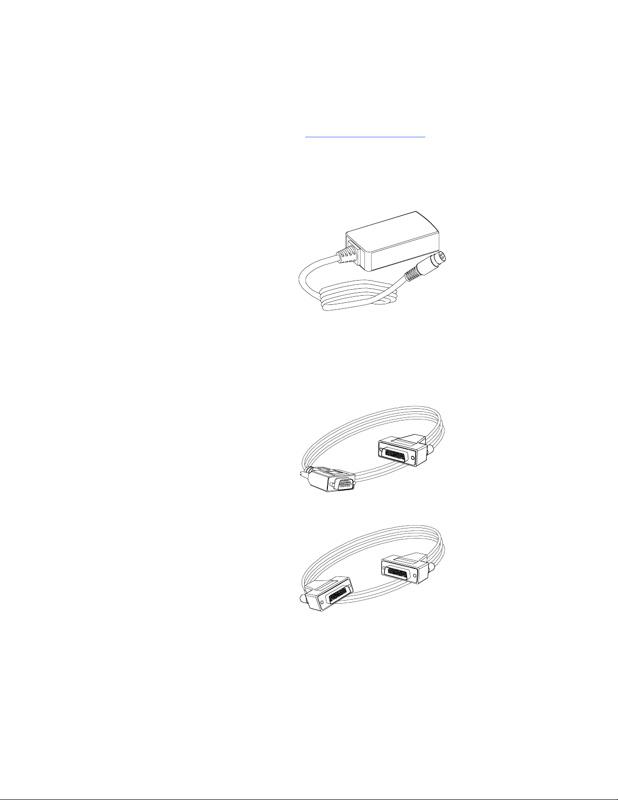
Power Supply
SMART provides a 12V, 5.0A power supply and the cable you need to connect it to a
power outlet (depending on your region).
.
Cables and Adapters
SMART provides the following cables:
• 6' (1.8 m) DVI male to VGA male cable to connect the Extended Control Panel
(ECP) from the DVI-out port.
• 6' (1.8 m) DVI male to DVI male cable to use if the display supports DVI ports.
Page 11

5 | CHAPTER 1 – WELCOME
• DVI male to VGA female adapter to connect the SMART Hub SE240 to a projector
or display using a VGA cable. Use this adapter if you use an Actalyst interactive
overlay or a SMART Board interactive display frame.
Page 12

6 | CHAPTER 1 – WELCOME
Page 13

Chapter 2
Configuring Your Hub
This chapter contains information on the following topics:
• Orienting Your SMART Product on page 8
• Connecting Your Computer to a Hub on page 8
• Connecting Video Sources to Your Hub on page 10
• Configuring the Display Settings on page 11
• Configuring Your Network and Conferencing Settings on page 11
• SMART Bridgit Software on page 14
• Configuring Room Control Settings on page 17
• Connecting to Computers and Video Sources on page 22
• Configuring Language and General System Settings on page 23
• Disabling Your System Hardware Features on page 24
• Configuring your TFTP/SNTP Servers on page 24
• Initializing Synchronization on page 25
• Configuring SNTP Settings on page 26
• Configuration Settings and Files on page 27
• Exporting and Importing Configuration on page 31
• Securing Configuration Settings on page 32
Page 14

8 | CHAPTER 2 – CONFIGURING YOUR HUB
Orienting Your SMART Product
When your SMART product uses its default orientation data, the touch point on the
screen corresponds to the projected image, provided the projected image fills the
entire interactive screen. However, the projected touch point might be offset from the
actual touch point in some situations. Resolve this issue by orienting your
SMART product.
IMPORTANT
• Before orienting your hub, download the latest version of firmware for your
hub from the SMAR
• Orient your SMART product with your hub before orienting it with other
connected computers.
T Support website.
To orient your SMART
product with your hub
1. Select System > Settings.
The Settings dialog box appears.
2. Press Orient.
The orientation screen appears.
3. Using a pen tray pen, press and release the center of the first target.
4. Repeat step 3 for each target.
The orientation data saves to your hub’s memory.
Connecting Your Computer to a Hub
You can connect two computers to the SMART Hub SE240, and one computer to the
SMART Hub VE220 to view input on your SMART product’s display. Both models
enable you to:
• Write and draw in digital ink.
• Freeze the display.
• Take screen captures.
• Use the on-screen keyboard and right-click features of your hub firmware.
Page 15
9 | CHAPTER 2 – CONFIGURING YOUR HUB
To connect your hub
to a computer
To configure your hub
for the computer
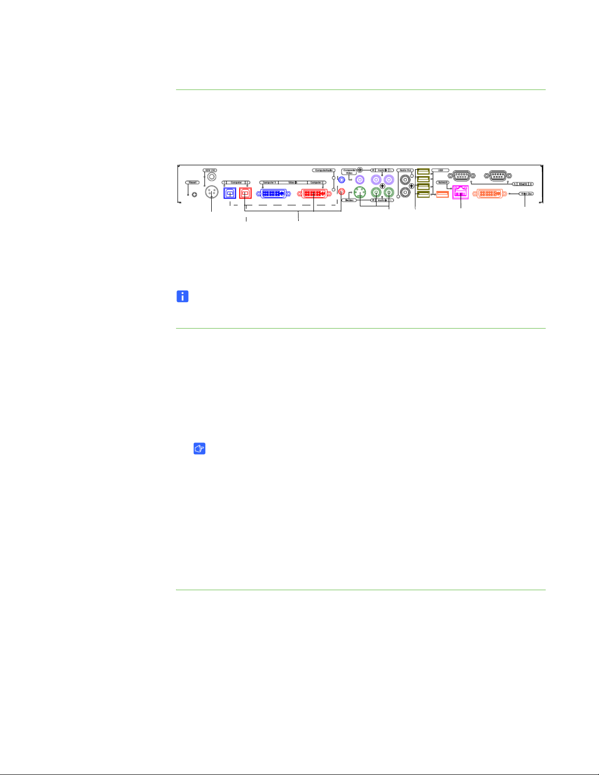
Connect the computer to the SMART Hub SE240 using the appropriate cables
and connectors.
Power
Source
Computer 1
Computer 2
Video
Source
1
Video
Source
2
USB
Storage
Devices,
Keyboard
and
Mouse
Network
NOTE
The SMART product and audio connections are optional.
1. Select System > Settings.
The Settings dialog box appears.
2. Press Input Configuration.
Display
3. In the Input device name box, type a name for the computer.
4. In the Input Type list, select Analog or Digital.
IMPORTANT
–Select Analog if you are using a VGA/DVI-I cable, or if you are using a
DVI/DVI cable with a VGA/DVI adapter.
–Select Digital if you are using a DVI/DVI cable.
– If the setup is incorrect, your hub will not work with a Mac computer.
5. Press Apply All.
A Picture Settings dialog box appears allowing you to change your hub’s
brightness or contrast. Press Adjust Settings, OK, Cancel or Reset accordingly.
Page 16

10 | CHAPTER 2 – CONFIGURING YOUR HUB
Connecting Video Sources to Your Hub
IMPORTANT
This section applies to the SMART Hub SE240 only.
You can connect up to two video sources to your SMART Hub SE240. Video sources
include DVD players, VCRs and similar devices. After connecting a video source to
your SMART Hub SE240, you can view its input on your SMART product’s interactive
screen and do the following:
• Draw digital ink notes.
• Freeze the display.
• Take screen captures.
To connect a video source Connect the video source to the SMART Hub SE240 using the appropriate cables and
connectors.
To configure your hub for
the video source
NOTE
Audio connections are optional.
Video Source Video (A) Audio (B)
1 4-pin mini-DIN connector
S-video
2 RCA video connector RCA audio connector set 2
1. Select System > Settings.
The SMART Hub SE240 Settings dialog box appears.
2. Press Input Configuration.
3. Press S-Video if you’re configuring your hub for the first video source, or press
Composite if you’re configuring your hub for the second video source.
4. In the Input device name box, type a name for the video source.
5. Press Apply All.
RCA audio connector set 1
Page 17

11 | CHAPTER 2 – CONFIGURING YOUR HUB
Configuring the Display Settings
You can configure your hub’s resolution and time-out settings to work with your
SMART product’s display.
To configure the
display settings
1. Select System > Settings.
The Settings dialog box appears.
2. Press Display Configuration.
TIP
The top portion of the Display Configuration tab shows information about the
projector or display connected to your hub. You can refresh this information by
pressing Refresh.
3. Select a resolution in the Resolution list.
4. Select additional options, including how many minutes you want your hub to wait
before it enters sleep mode, shuts down the projector, or displays the device’s
control strip.
5. Press Apply All.
Configuring Your Network and Conferencing Settings
To configure basic
networking settings
Connect your hub to a network to take advantage of its networking features such as
e-mailing Whiteboard files.
IMPORTANT
You must be familiar with basic networking, Simple Network Management
Protocol (SNMP) and Simple Mail Transfer Protocol (SMTP) to complete the
following procedures. If you aren’t familiar with these concepts, consult an
information technology professional in your organization.
1. Select Systems > Settings.
The Settings dialog box appears.
2. Press Network for the VE220, or Network and Conferencing for the SE240, and
then type a name for your hub in the Device name/network ID box.
3. Press the Network Address tab, and then select the Use DHCP (automatically
detect network settings) option to configure networking settings automatically.
Page 18

12 | CHAPTER 2 – CONFIGURING YOUR HUB
OR
Select the Manually specify network settings and addresses option to
configure networking settings manually, and then type the appropriate information
(as supplied by your network administrator) in the :
– IP address
– Subnet mask
– Default gateway
– DNS server 1
– DNS server 2
4. Press Apply All.
TIP
You can reset your unit to ensure your settings are applied.
To configure e-mail
(SMTP) settings
1. Select System > Settings.
The Settings dialog box appears.
2. If you have a SMART Hub SE240, select Network and Conference, and then
press E-Mail (SMTP).
OR
If you have a SMART Hub VE220, select Network, and then press
E-Mail (SMTP).
3. Type the name of your SMTP server in the SMTP server name box, and then type
the port number of your SMTP server in the Port number box.
NOTE
The SMTP’s default port number is 25.
4. Type the domain name of the SMTP server in the Domain name box.
NOTES
– Select the Enable file export by e-mail check box to enable file
export by e-mail.
– Select the Enable RJ45 Ethernet port check box to enable the
networking features on the Administration tab.
5. Press Apply All.
Page 19

13 | CHAPTER 2 – CONFIGURING YOUR HUB
To configure network
management
(SNMP) settings
1. Select System > Settings.
The Settings dialog box appears.
2. If you have a SMART Hub SE240, select Network and Conference, and then
press Management, Room Control.
NOTE
The Room Control feature isn’t available with the SMART Hub VE220.
3. Select Use the settings as the SNMP read/write strings to use the general
settings for the SNMP read/write strings.
OR
Select Manually assign SNMP read/write strings, and then enter the
appropriate information (as supplied by your network administrator) to manually
assign the SNMP read/write strings.
– Read community string
– Write community string
4. If you have a SMART Hub SE240, select the Enable remote management of
SMART Hub SE240 checkbox.
OR
If you have a SMART Hub VE220, select the Enable remote management of
SMART Hub VE220 checkbox.
NOTE
In SNMP, community strings are text strings that act as s. “Get” requests are
only valid if their community strings match the value in the Read community
string box, and “Set” requests are only valid if their community strings match
the value in the Write community string box.
5. Type the IP address to which your hub should send traps (as supplied by your
network administrator) in the Trap destination address box.
NOTE
Traps are unsolicited, asynchronous events that devices such as the SMART
Hub uses to indicate status changes.
6. Press Apply All.
Page 20

14 | CHAPTER 2 – CONFIGURING YOUR HUB
NOTE
To fully utilize the SNMP features, download the SMART Hub’s Management
Information Base (MIB) files from www.smarttech.com/SE240firmware
SMART Hub SE240, or www.smarttech.com/VE220firmware
Hub VE220. SNMP management software uses MIB files to interpret the
devices that it monitors.
for the SMART
for the
SMART Bridgit Software
IMPORTANT
This section applies to the SMART Hub SE240 only.
SMART Bridgit software is a client/server application that lets you collaborate with
anyone, anywhere in the world. Using SMART Bridgit, you can:
• Share your display.
• View other participants’ displays.
• Communicate with others through chat.
• Use your SMART product to write digital ink notes.
IMPORTANT
To use your hub’s SMART Bridgit features, do one of the following:
• Purchase and install SMART Bridgit software.
• Purchase a subscription for the SMART Bridgit service.
• Install a trial version of SMART Bridgit for 30 days, and then purchase the
server software or service from an authori
• Be invited to a meeting by a person or organization with SMART
Bridgit software.
For more information on these options, see the SMART Bridg
SMART Support website.
zed SMART reseller.
it page of the
Page 21

15 | CHAPTER 2 – CONFIGURING YOUR HUB
Configuring SMART Bridgit Software
To configure SMART
Bridgit software
1. Select System > Settings.
The SMART Hub SE240 Settings dialog box appears.
2. Press Network and Conference, and then press the Conferencing tab.
3. Select the Enable conferences with Bridgit software check box.
4. In the Bridgit server box, type the URL of the SMART Bridgit server (for example,
bridgit.yourcompany.com).
5. In the Default meeting box, type a default, easy-to-identify name for all SMART
Bridgit meetings created with your hub.
6. In the Viewing Password box, type a that participants must enter to view SMART
Bridgit meetings.
7. In the Creation Password box, type a password that participants must enter to
create SMART Bridgit meetings, and then press Apply All.
Creating a SMART Bridgit Meeting
IMPORTANT
• This section applies to the SMART Hub SE240 only.
To change the meeting’s
name and
• You must connect your hub to a network and configure it to use SMART
Bridgit software.
SMART Bridgit meetings start automatically once you configure SMART Bridgit.
TIP
For more information on SMART Bridgit, see the SMART Bridgit 4.0 Software
User’s Guide (document 142511
Select System > Change Meeting Name and Password to change the meeting’s
name and .
NOTE
If you’re a meeting owner, you also have the option of removing current attendees
from the meeting.
).
Page 22

16 | CHAPTER 2 – CONFIGURING YOUR HUB
To share your display Press Share Screen at the top of your screen.
A blue border appears around your display.
NOTE
If you and another participant are in the same SMART Bridgit meeting, the
meeting’s owner must approve your request before you can share your display.
To stop sharing
your display
To configure the SMART
Bridgit meeting settings
Select Stop Sharing.
The blue border around your display disappears.
Configuring the SMART Bridgit Software Meeting Settings
If you’re the owner or presenter of a SMART Bridgit meeting, you can configure
whether other participants can:
• Write digital ink notes when you’re sharing your display.
• Share their displays.
•Chat.
• Request remote control when you’re sharing your display.
1. Select System > Advanced Settings at the top of your screen.
The Meeting Options dialog box appears.
2. Select the Allow others to draw check box to allow participants’ notes when
you’re sharing your display.
3. Select the Allow others to share their display check box to allow participants to
share their displays.
4. Select Allow others to use chat check box to allow participants to chat.
5. Select the Allow others to use remote control check box to allow participants to
request remote control when you’re sharing your display, and then press OK.
Page 23

17 | CHAPTER 2 – CONFIGURING YOUR HUB
Leaving a SMART Bridgit Meeting
You can leave a SMART Bridgit meeting at any time.
To leave a SMART
Bridgit meeting
Select Settings > Leave Meeting.
NOTE
When prompted to disconnect the remaining participants, press Yes. The meeting
ends and the other participants are disconnected. If you press No, only you
disconnect, but the meeting continues.
Configuring Room Control Settings
IMPORTANT
This section applies to the SMART Hub SE240 only.
You can control the SMART Hub SE240 externally with a computer or room control
system using a TELNET session established over a TCP/IP network connection or
through a serial (RS-232) connection. This allows you to select inputs, control audio
volume, request information such as projector lamp usage or network settings and
complete other tasks.
This section describes how to configure the SMART Hub SE240 for external control
using a computer or room control system, and the commands you use to change and
view the projector or display settings.
Enabling and Using Room Control Settings through the Serial Interface
To enable and use the SMART Hub SE240’s room control settings, complete the
following procedures:
1. Connect the computer or room control system to the SMART Hub SE240.
2. Enable your hub’s room control mode.
3. Configure the connected computer or room control system’s serial interface.
4. Program your room control system to use the hub’s room control commands.
Page 24

18 | CHAPTER 2 – CONFIGURING YOUR HUB
To connect the computer
or room control
system to your hub
To enable your hub’s
room control mode
To configure your serial
interface settings
Connect your hub to the computer or room control system using the female RS-232
connector.
NOTE
The female RS-232 connector is for room control only.
1. Select System > Settings.
The SMART Hub SE240 Settings dialog box appears.
2. Select Administration, and then select the Enable room control with RS-232
check box.
3. Press Apply All.
You can’t configure the SMART Hub SE240’s serial interface settings. Therefore,
configure your computer’s serial communication program, such as Microsoft®
HyperTerminal or your room control system’s serial communication settings, to the
following values.
Setting Value
To verify that the
serial interface is
in room control mode
Data rate 9600 bps
Data bits 8
Parity None
Stop bits 1
Flow control None
1. Turn on your communication program.
2. Configure your communication program as documented in the previous section.
3. Press ENTER.
If your configuration is correct and the SMART Hub SE240 is in room control
mode, the > character appears.
Page 25

19 | CHAPTER 2 – CONFIGURING YOUR HUB
Enabling and Using Room Control Settings through TELNET
IMPORTANT
This section applies to the SMART Hub SE240 only.
Instead of connecting the SMART Hub SE240 to room control through the serial
interface, you can connect through TELNET.
To connect the computer
or room control system
through TELNET
1. Connect your hub and the computer or room control system to the same network.
2. Select System > Settings.
The SMART Hub SE240 Settings dialog box appears.
3. Select Network and Conference, and then press Management, Room Control.
4. Select the Enable room control via TELNET check box.
5. In the Port number text box, type the port number for TELNET.
NOTE
TELNET’s default port number is 23.
6. Press Apply All.
Command Summary for Your SMART Hub SE40
IMPORTANT
This section applies to the SMART Hub SE240, TELNET and RS-232 only.
The SMART Hub SE240 responds to the following types of commands:
• Power state
• Input selection
• Video and audio
• System information
NOTES
– Press ENTER after each command.
– Commands aren’t case-sensitive.
Page 26

20 | CHAPTER 2 – CONFIGURING YOUR HUB
Power State Commands
Command Description
on Turns on the SMART Hub SE240.
off Turns off the SMART Hub SE240 (only with a projector).
get powerstate Requests the SMART Hub SE240 power state.
Possible returned values when using your hub with a
SMART UF55, SMART UF55w, UX60 or Unifi™ projector:
•startup
•on
• shutdown
•off
Possible returned values when not using your hub with a
SMART UF55, SMART UF55w, UX60 or Unifi projector:
•on
• standby
Input Selection Commands
Command Description
set input dvi-1 Selects the first computer input.
set input dvi-2 Selects the second computer input.
set input composite Selects the composite video source input.
set input s-video Selects the S-video source input.
set input whiteboard Selects Whiteboard.
get input Requests the hub’s current input.
Page 27

21 | CHAPTER 2 – CONFIGURING YOUR HUB
Video and Audio Commands.
Command Description
set brightness {+ or -} Increases or decreases the brightness in
increments.
set brightness {0 – 100} Sets the brightness to an absolute value from 0 (off)
to 100 (full brightness).
get brightness Requests the hub’s current brightness setting.
set contrast {+ or –} Increases or decreases the contrast in increments.
set contrast {0 – 100} Sets the contrast to an absolute value from 0
(minimum contrast) to 100 (maximum contrast).
get contrast Requests the hub’s current contrast setting.
set volume {+ or -} Increases or decreases the volume in increments.
set volume {0 – 30} Sets the volume to slightly audible mode.
get volume Requests the hub’s current volume setting.
set mute {on or off} Turns your hub’s mute feature on and off.
get mute Requests the current mute setting.
set display {on or off} Turns the display’s video output feature on and off.
set timeout {0, 5, 10, 30 or 60} Modifies the sleep setting.
NOTE
Setting it to 0 turns sleep mode off.
factory reset Resets the settings to factory defaults.
type ? Requests a list of commands.
Page 28

22 | CHAPTER 2 – CONFIGURING YOUR HUB
System Information Commands
Command Description
get lamphrs Requests the number of hours that the projector
lamp has been in use (from 0 to 3000).
NOTE
This command only returns a value if the
SMART Hub SE240 is connected to a UF, UX
or Unifi projector.
get syshrs Requests the number of hours that the system has
been in use.
get ipaddr Requests the IP address.
get macaddr Requests the MAC address.
get fwver Requests the firmware version.
To view a connected
computer’s input
Connecting to Computers and Video Sources
IMPORTANT
This section applies to the SMART Hub SE240 only.
You can connect your hub to up to two computers and two video sources.
After connecting your hub to a computer or video source, you can view the computer
or video source’s input on your SMART product’s interactive screen.
NOTE
You can connect a computer with SMART Notebook™ software version 9.7 SP1
or later to your hub and use the digital ink features of the software. Your hub
doesn’t support earlier versions of SMART Notebook.
Press one of the computer input buttons on the sidebar.
The computer’s input appears.
NOTE
The default label of the first DVI input button is Computer One, and the default
label of the second DVI input button is Computer Two. You can change
these labels.
Page 29

23 | CHAPTER 2 – CONFIGURING YOUR HUB
To view a connected
video source’s input
Press one of the video source input buttons on the sidebar.
The video source’s input appears.
NOTE
The default label of the S-video input button is Video One, and the default label of
the composite input button is Video Two. You can change these labels.
Configuring Language and General System Settings
The hub’s user interface is set to English by default. You can change the language to
one of the following:
•French
•German
• Italian
• Spanish
To set the hub’s user
interface language
To view system
information
1. Select System > Settings.
The Settings dialog box appears.
2. Select System and Language.
3. In the Language list, select your preferred language.
4. Press Apply All.
You can view your hub’s system information, including the firmware version, Internet
Protocol (IP) address and Media Access Control (MAC) address.
1. Select System > Settings.
The Settings dialog box appears.
2. Press System and Language.
The system information displays.
Page 30

24 | CHAPTER 2 – CONFIGURING YOUR HUB
Disabling Your System Hardware Features
Disable your system hardware features if you want to disable your network port,
secure your settings or prevent anyone from using the hub to connect to a corporate
network.
To disable your system
hardware settings
1. Select System > Settings.
The Settings dialog box appears.
2. Press Administration.
3. Clear the Enable RJ45 Ethernet port check box to disable networking features.
4. Clear the Enable USB storage device support check box to disable USB
storage device features.
5. Press Apply All.
Configuring your TFTP/SNTP Servers
Your Trivial File Transfer Protocol (TFTP) server is the repository for your hub’s
firmware and configuration files. Your hub can check the TFTP server to see if any
new files are available, and then download and install any new files accordingly.
To configure your hub, you must enter a domain name or IP address for the TFTP
server, in addition to the port number.
A Simple Network Time Protocol (SNTP) server is used for time configuration.
Through the SNTP service, administrators can also check for updates at specific
times, and define the time they want to update.
IMPORTANT
You must be familiar with basic networking, TFTP and SNTP to complete the
following procedures. If you are not familiar with these concepts, refer this guide
to an information technology professional in your organization.
TFTP Server Configuration
A TFTP server must be set up on a network server. The system administrator decides
which TFTP server to use for the operating system they’re running on their server.
You only need a few requirements to configure your TFTP. Create a folder named
SMART under the TFTP server’s root directory. This is where you can locate the
synchronized SE/VE files.
Page 31

25 | CHAPTER 2 – CONFIGURING YOUR HUB
Configuration Files
The central configuration file located in the SMART folder holds all of the information
required to synchronize the hubs.
Inside the SMART folder, create a text file and name it Hub_SE240_firmware.cfg for
the SMART Hub SE240, or Hub_VE220_firmware.cfg for the SMART Hub VE220.
Then place the file in the SMART directory located on the TFTP server.
The content in the text files must follow the same file format as the settings
configuration files. Each line must contain a "key=value" pair. Refer to the Configuring
SNTP Settings on page 26 for a list of keys and their corresponding values, as all
actions are based on these pairs. To find these pairs, follow these instructions:
• Ignore lines with nothing but white space.
• Ignore lines with # signs in front as they are comments.
Initializing Synchronization
Once you’ve configured your TFTP server settings, you must create a synchronization
event by initiating synchronization, or scheduling an update.
Firmware Updates
You have to configure your firmware updates. To do so, add
_TFTP_APP_NAME=<name of bin file> to the Hub_SE240_firmware.cfg or Hub
VE220_firmware.cfg file.
For example, to update new SE240 firmware to a newer version, put
Hub_SE240_firmware.cfg contents into the SMART folder. This is the TFTP server/
firmware location configuration file. It identifies what version of firmware the hub
should load when it connects to the TFTP server.
IMPORTANT
This file must be named Hub_SE240_firmware.cfg or
Hub_VE220_firmware.cfg.
The next time your hub checks the TFTP server for data, it sees that the TFTP
should be running the version identified by
Hub_SE240_app_v2.4.3.0_09-06-03.bin.
If it isn’t, it downloads the file from the SMART folder on the TFTP server and
reboots after the new firmware installs.
Page 32

26 | CHAPTER 2 – CONFIGURING YOUR HUB
Updating Your Hub’s Firmware
To update your
hub’s firmware
To update SNTP/TFTP
configurations
Press your hub’s Update Now button.
You can also schedule your hub to perform daily updates at specific times.
Configuring SNTP Settings
As with TFTP, you must set up an SNTP server on a separate computer, and then
configure the hubs to communicate with the SNTP server through a specified domain/
IP computer address and port number.
One you’ve configured the SNTP server, the current time will show the time according
to the SNTP server. Once the hubs’ time is set, the configuration determines when the
TFTP updates will occur.
1. Select System >Settings.
The Settings dialog box appears.
2. If you have a SMART Hub SE240, press Network and Conference.
OR
If you have a SMART Hub VE220, press Network.
3. Press Update (SNTP/TFTP).
4. Type a name for the server in the SNTP server box in the SNTP settings, and then
type 123 in the Port number box.
5. Type a name for the server in the TFTP server box in the TFTP settings, and then
type 69 in the Port number box.
Page 33

27 | CHAPTER 2 – CONFIGURING YOUR HUB
Configuration Settings and Files
NOTE
Some of these settings don’t apply to the SMART Hub SE240. They apply to the
SMART Hub VE220 only.
Key Value Description
Language • English
• Français
• Italiano
• Español
•Deutsch
In1EDID • Analog
• Digital
In2EDID • Analog
• Digital
OutputFormat • SVGA (800 × 600), 60 Hz
• XGA (1024 × 768), 60 Hz
• WXGA (1360 × 768), 60 Hz
• WXGA (1280 × 800), 60 Hz
• SXGA (1280 × 1024),
• 720p (1280 × 720), 50 Hz
• 1080i (1920 × 1080), 50 Hz
60 Hz
Sets system to a specified
language.
Configures the EDID data on the
Computer Input #1 to return
analog or digital data.
Configures the EDID data on the
Computer Input #2 to return
analog or digital data.
Configures the output
resolution.
• 1080p (1920 × 1080), 50 Hz
• 1080p (1920 × 1080), 30 Hz
SleepTimeout • 5 minutes
•10 minutes
•15 minutes
•30 minutes
•45 minutes
•60 minutes
•No timeout
Sets the elapsed time before the
video output enters
sleep mode.
Page 34

28 | CHAPTER 2 – CONFIGURING YOUR HUB
Key Value Description
ShutdownTimeout • 15 minutes
•30 minutes
•45 minutes
Sets the elapsed time before a
configured projector
turns off.
•60 minutes
•No timeout
bridBridgitServer User defined Provides the server’s name. For
example,
bridgit.smarttech.com
(SE240 only).
bridViewPassword User defined Shows the for the SMART
Bridgit server
(SE240 only).
bridCreatePassword User defined Creates a meeting for the
SMART Bridgit server (SE240
only).
bridDefaultConf User defined Default SMART Bridgit meeting
name, unless otherwise
specified (SE240 only).
bridEnabled • false
•true
Enables SMART Bridgit
conferencing (SE240 only).
DVI1Label User defined DVI #1 Input label
DVI2Label User defined DVI #2 Input label
(SE240 only).
SVideoLabel User defined S-Video Input label
(SE240 only).
CompositeLabel User defined Composite Input label
(SE 240 only).
SMTP Enable • false
Enables SMTP support.
•true
SMTPServer User defined Uses the SMTP server. For
instance mail.smarttech.com.
SMTPPortNum User defined Use 25 as the default number for
the SMTP port.
TFTPServer User defined Use the TFTP server to
configure your hub.
Page 35

29 | CHAPTER 2 – CONFIGURING YOUR HUB
Key Value Description
TFTPPortNum User defined Use 69 as the TFTP
port number.
SNTPServer User defined Use the SNTP server. For
instance, time-a.nist.gov.
SNTPPortNum User defined Use 123 as the SNTP
port number.
SNMPEnable • false
Enables SNMP support.
•true
AUTO_UPDATE_MODE
0: Disabled
1. 00:00:00
2. 04:00:00
Time in SNTP at which your hub
checks the TFTP server for
updated settings or
configuration information.
3. 08:00:00
4. 12:00:00
5. 16:00:00
6. 20:00:00
SNMPUseSettingsP/W
•false
•true
Uses the settings instead of
manually configuring the read/
write
community strings.
SNMPSysContact User defined System contact information.
SNMPSysLocation User defined System location information.
SNMPReadCom-
User defined SNMP read community string.
mString
SNMPWriteCom-
User defined SNMP write community string.
mString
SNMPTrapAddress User defined Sends your SNMP traps to
this location.
RmCtlTelnetEnable • false
•true
Enables TELNET room control
(SE240 only).
RmCtlTelnetPortNum User defined Uses 23 as the port’s
default number.
EthernetEnable • false
Enables the Ethernet port.
•true
USBStorageEnable • false
Enables USB storage support.
•true
Page 36

30 | CHAPTER 2 – CONFIGURING YOUR HUB
Key Value Description
RoomcontrolEnable • false
•true
SettingsReqP/W • false
•true
Enables room control
(SE240 only).
Creates a to modify settings
from the
settings menu.
SettingsLmtdAccess • false
•true
Enables limited access to
settings without a .
SettingsPassword User defined Creates a settings to gain
limited access to the
above settings.
DisplayControlFile • None
• Automatically detect
• SMART\NEC42_50_60XP10S
cript.lua
• SMART\UF55_UX60Script.lua
• SMART\UF45Script.lua
• User defined
Uses this file to control
attached displays.
ImportDisplayFile User defined Import this file’s name into
the hub.
_TFTP_APP_NAME User defined Download and run
this application.
_PRODUCT_KEY SE-ЧЧЧЧЧ-ЧЧЧЧЧ-ЧЧЧЧЧ-
ЧЧЧЧЧ
Uses the product key number to
upgrade your VE220
(or several VE220s), to
an SE240.
_ACTIVATION_KEY ЧЧЧЧ-ЧЧЧЧЧ-ЧЧЧЧЧ-ЧЧЧЧЧЧ-
××××
Uses the activation key specific
to your SMART Hub VE220 to
obtain a product key number.
Page 37

31 | CHAPTER 2 – CONFIGURING YOUR HUB
Exporting and Importing Configuration
If you have more than one hub, you can configure one unit, export the configuration
settings to a USB storage device, and then import the configuration settings to the
other units.
NOTES
• Procedures vary depending on whether you have a SMART Hub SE240 or a
SMART Hub VE220.
• The export process doesn’t include orientation data on the USB
storage device.
To export configuration
settings to a USB
storage device
1. Connect a USB storage device to your hub.
2. Select System > Settings.
NOTE
If a is required to change the configuration settings, type the in the box at the
bottom of the menu, and then press OK.
3. Press Administration, and then ensure the Enable USB storage device support
check box is selected.
4. Press Export Settings.
The Settings dialog box appears.
5. Select either the SMART Hub SE240 system settings check box or the SMART
Hub VE220 system settings check box.
6. Select the E-mail Contacts check box to import/export contacts.
7. Press OK, and then press OK again.
Page 38

32 | CHAPTER 2 – CONFIGURING YOUR HUB
To import configuration
settings from a USB
storage device
1. Connect the USB storage device to your hub.
2. Select System > Settings.
3. Press Administration, and then ensure the Enable USB storage device support
check box is selected.
4. Press Import Settings.
The Settings dialog box appears.
5. Select the SMART Hub SE240 system settings check box or the SMART Hub
VE220 system settings to import configuration settings, and the E-mail
Contacts check box to import your contacts.
6. Press OK.
The Settings dialog box appears.
7. Press Restart to end the current session and start a new session using the
imported configuration settings.
Securing Configuration Settings
To apply a to
configuration settings
You can assign a to protect the configuration settings.
1. Select Systems > Settings.
The Settings dialog box appears.
2. Press Administration.
3. Select the Require to access system settings check box to require users to enter
a to change the configuration settings.
The Settings dialog box appears.
NOTE
If the Require to access system settings check box was previously selected,
press Set Password to open the Settings Administrator Password dialog box.
4. Type the in the Password and Confirm boxes, and then press OK.
5. Select the Enable limited access to settings without check box to allow users
to change the display settings and language settings, but not change
other settings.
6. Press Apply All.
Page 39

Chapter 3
Using Your Hub
This chapter contains information on the following topics:
• Basic Tools on page 34
• System Help on page 35
• Starting Your Hub Session on page 35
• Whiteboarding on page 36
• Saving or E-Mailing a File on page 37
• Using Your SMART Product with Computer Inputs on page 38
Page 40

34 | CHAPTER 3 – USING YOUR HUB
Basic Tools
Sidebar
For the SMART Hub SE240, the sidebar menu allows you to move between SMART
Bridgit meetings, computer and video source sessions and Whiteboarding. See the
Using Your SMART Hub VE220 Quick Reference (document 144102
SMART Hub VE220.
For the SMART Hub VE220, the sidebar helps you navigate between features. See
the Using Your SMART Hub SE240 Quick Reference (document 124621
a SMART Hub SE240.
Page Sorter
The page sorter helps you navigate through your pages.
NOTE
To minimize the sidebar, press the Collapse button. To move the sidebar, press
the Move Toolbar button.
) if you have a
) if you have
To access the
SMART Keyboard
SMART Keyboard
If there’s no keyboard connected to your hub, you can use SMART’s on-screen
keyboard to type information.
Press the Keyboard button.
The SMART Keyboard appears.
NOTE
The button appears at the right end of many text boxes, and on the sidebar when
you’re in Computer mode.
Right-Click
If you connect a computer to your hub and there’s no mouse connected, you can
simulate a right-click by pressing the interactive whiteboard’s Right-Click button, and
then pressing the interactive screen with your finger.
Page 41

35 | CHAPTER 3 – USING YOUR HUB
Volume Adjustment
If your hub is connected to speakers, adjust the volume by pressing Volume.
Adjust the volume by moving the slider up to increase the volume, or down to
decrease the volume.
NOTE
You can also control volume adjustment through the volume button on the
SystemOn Module connected to the pen tray.
System Help
Your hub includes Help.
To view Help 1. Select System > Help.
2. Press a help topic to view the associated information.
Starting Your Hub Session
There are three ways to start a new session.
Situation Procedure
Your SMART product is turned off. Turn on your SMART product as
Your SMART product is turned on, but
the display is blank.
Your hub has timed out and is in
Sleep mode.
documented in the user’s guide.
Swipe your finger or a pen tray pen
across your SMART product’s display.
Swipe your finger or a pen tray pen
across your SMART product’s display.
Page 42

36 | CHAPTER 3 – USING YOUR HUB
Whiteboarding
Whiteboard allows you to capture notes and drawings in digital ink on your SMART
product. Use Whiteboard for brainstorming, note-taking and other activities for
which you want to use your SMART product’s digital ink tools without connecting
to a computer.
To create a file Press the New File button.
A new file opens.
To open a file 1. Connect the USB storage device that contains the Whiteboard file to your hub,
and then press the File Open button.
The File browser dialog box appears.
2. Select the USB storage device’s drive letter in the Look In list, and then browse to
and select the file.
3. Press Open.
The file opens.
To add a pa g e Press the Add Page button.
A new page appears after the current page.
To delete a page 1. Select the page you want to delete, and then press the Delete Page button.
A delete page confirmation appears.
2. Press OK to delete the page.
Page 43

37 | CHAPTER 3 – USING YOUR HUB
Saving or E-Mailing a File
You can save your file on a USB storage device or e-mail it in one of the
following formats:
• Whiteboard file (.notebook)
• JPEG archive (.zip)
• Portable Document Format (.pdf)
After saving a file on a USB storage device, you can open, view and edit on a
computer with SMART Notebook or SMART Meeting Pro™ software.
To save a file 1. Connect a USB storage device to your hub.
2. Press the Save button.
3. Select the USB storage device’s drive letter in the Look In list.
4. Browse to the folder where you want to save the file.
NOTE
Press the New Folder button to create a new folder for the file.
5. Type a file name in the File Name box.
6. Select a file type in the Save as type list.
• Whiteboard file (.notebook)
• JPEG archive (.zip)
• Portable Document Format (.pdf)
NOTE
If you select JPEG Archive (.zip), your hub saves each page in the
Whiteboard file as a JPEG image and then archives them in a single zip file.
7. Press Save.
Page 44

38 | CHAPTER 3 – USING YOUR HUB
To e-mail a file 1. Press the E-mail button.
The File Browser dialog box appears.
2. Select the recipient in the Recipient list.
OR
Type the recipient’s e-mail address in the E-mail address box.
NOTES
– Add a new recipient or edit the list of recipients by pressing the
appropriate button in the upper right corner of the E-mail dialog box.
– If you’re using the on-screen keyboard to type e-mail addresses, press
SHIFT + 2 for the @ symbol.
3. In the Save as type list, select a file type.
• Whiteboard file (.notebook)
To draw digital ink notes
on the display
• JPEG archive (.zip)
• Portable Document Format (.pdf)
NOTE
If you select JPEG Archive (.zip), your hub saves each page in the
Whiteboard file as a JPEG image and then archives them in a single zip file.
4. Press Send E-mail.
Using Your SMART Product with Computer Inputs
When viewing computer input, you can draw digital ink notes on the display. If you
want to save your digital ink notes, you can take a screen capture of the display.
1. Pick up a pen tray pen.
OR
Press the Pen button on the sidebar.
2. In the pen toolbar, select the appropriate color and thickness options, and then
draw digital ink.
Page 45

39 | CHAPTER 3 – USING YOUR HUB
To erase digital ink 1. Pick up the eraser from your SMART product’s pen tray.
OR
Press the Eraser button on the sidebar.
2. Erase your digital ink notes.
To clear the display Press the Clear button.
Digital ink notes disappear from the display.
To freeze the display Press the Freeze button.
The display freezes.
To capture the display Press the Capture button.
The last page in the page sorter contains a screen capture of the display.
Page 46

40 | CHAPTER 3 – USING YOUR HUB
Page 47

Chapter 4
Maintaining Your SMART Hub
This chapter contains information on the following topics:
• Enabling Your Hub’s Audio Feature on page 42
• Updating the SMART Hub SE240’s Firmware on page 43
• Upgrading to a SMART Hub SE240 on page 44
Page 48

42 | CHAPTER 4 – MAINTAINING YOUR SMART HUB
Enabling Your Hub’s Audio Feature
If you want to access your hub’s audio feature, you need to remove your hub’s
cover plate.
IMPORTANT
This section applies to the SMART Hub VE220 only.
To remove the
hub’s cover plate
To enable the hub’s
audio feature
1. Using a Phillips No. 1 screwdriver, remove the two screws securing the hub’s
cover plate.
2. Pry the plastic cover off of the hub with a flat-headed screwdriver, or a
similar device.
NOTE
An adhesive glue holds the plastic plate to the hub. Don’t use a lot of force
when removing the plate.
You now have access to the hub’s audio feature.
Once you’ve removed the hub’s cover plate, connect a 3.5 mm audio cable to Port
one, as per the diagram below. Only the Audio In and Audio Out ports are enabled on
this hub.
Do not use cables in any of the other ports.
Audio In
Audio Out
Page 49

43 | CHAPTER 4 – MAINTAINING YOUR SMART HUB
Updating the SMART Hub SE240’s Firmware
SMART periodically releases firmware updates that introduce new functions or correct
known issues with existing functions.
You can update your hub’s firmware using a USB storage device.
To determine if an
update is required
To update the
firmware
1. Select System > Settings.
The Settings dialog box appears.
2. Press System & Language.
The current version of the firmware appears in the System Information section
of the tab.
3. Go to www.smarttech.com/SE240firmware
www.smarttech.com/VE220firmware
latest available version of the firmware.
NOTE
If the latest version of the firmware is newer (if the number is higher) than your
current version, you need to update the firmware.
1. Connect the USB storage device to a computer with Internet access.
2. Go to www.smarttech.com/SE240firmware
OR
Go to www.smarttech.com/VE220firmware
for the SMART Hub SE240 or
for the SMART Hub VE220 to determine the
for the SMART Hub SE240.
for the SMART Hub VE220.
3. Download the latest version’s application files to the following location on the USB
storage device:
\SMART\
4. Disconnect the USB storage device from the computer, and then connect it to one
of the USB A receptacles on your hub.
5. Select Systems > Settings.
The Settings dialog box appears.
Page 50

44 | CHAPTER 4 – MAINTAINING YOUR SMART HUB
6. Select Administration > Firmware Update.
The Settings dialog box appears.
7. Select the Bootloader check box, and then press OK.
8. Press Restart.
NOTE
The initial reset after updating the firmware can take several minutes.
Upgrading to a SMART Hub SE240
You can upgrade your SMART Hub VE220 to a SMART Hub SE240 for additional
features and benefits, such as:
• collaboration with remote computers using SMART Bridgit software
• more extensive audio and video input and output options
To upgrade your SMART
Hub VE220 firmware
• serial room control capability
• ability to make notes over video sources
IMPORTANT
Before you can upgrade your SMART Hub VE220, you must purchase a
product upgrade key from your authorized SMART reseller
1. Select System > Settings.
2. Press Upgrade Hub to SE240.
3. Type the product key number into the Product Key box.
NOTE
The product key number follows this format: SE-XXXX-XXXX-XXXX-XXXX.
4. If you have an Internet connection, press Upgrade.
OR
If you don’t have an Internet connection and are activating your hub manually,
select Manual Activation, and then type your activation key.
NOTES
– If you don’t have an Internet connection, contact
SMART Technical Support
must provide your product key and installation ID in order to receive your
activation key.
and they will send you an activation key. You
.
– You only need to request an activation key if you don’t have an Internet
connection and are activating your hub manually.
Page 51

45 | CHAPTER 4 – MAINTAINING YOUR SMART HUB
Upgrading Your SMART Hub VE220 Using a Product Key File
IMPORTANT
This section applies to the SMART Hub VE220 only.
To upgrade your VE220
using a product key file
1. Connect a USB storage device to your computer’s USB interface.
2. Create a folder named SMART on the USB storage device.
3. Create a text file with the following text:
_PRODUCT_KEY =SE-XXXX-XXXX-XXXX-XXXX
Replace the XXXX section with your product key.
4. Save the file as SMART_upgrade_keys.txt in the SMART folder on the USB
storage device.
5. If you have an activation key, you can add it to the text file in this format:
_ACTIVATION _KEY = XXXXXXXXXXXXXXXXXXXXXX
NOTE
If you don’t have your activation key, contact the SMART Support site
they will send it to you. You must provide your product key and installation ID
in order to receive your activation key.
6. Disconnect the USB storage device from your computer and connect it to the
SMART Hub VE220’s USB interface.
7. Select System > Settings.
and
8. Select Upgrade Hub to SE240.
9. Press the Get from File button.
10. Press Upgrade.
NOTES
– You don’t have to type dashes when you enter your activation or product
key numbers.
– Your Installation ID is unique to your SMART Hub VE220.
Page 52

46 | CHAPTER 4 – MAINTAINING YOUR SMART HUB
Page 53

Appendix A
Hardware Environmental Compliance
SMART Technologies supports global efforts to ensure that electronic equipment is
manufactured, sold and disposed of in a safe and environmentally friendly manner.
Waste Electrical and Electronic Equipment Regulations (WEEE Directive)
Waste Electrical and Electronic Equipment regulations apply to all electrical and
electronic equipment sold within the European Union.
When you dispose of any electrical or electronic equipment, including SMART
Technologies products, we strongly encourage you to properly recycle the electronic
product when it has reached end of its life. If you require further information, please
contact your reseller or SMART Technologies for information on which recycling
agency to contact.
Restriction of Certain Hazardous Substances (RoHS Directive)
This product meets the requirements of the European Union’s Restriction of Certain
Hazardous Substances (RoHS) Directive 2002/95/EC.
Consequently, this product also complies with other regulations that have arisen in
various geographical areas, and that reference the European Union’s RoHS directive.
Page 54

48 | APPENDIX A – HARDWARE ENVIRONMENTAL COMPLIANCE
Packaging
Many countries have regulations restricting the use of certain heavy metals in product
packaging. The packaging used by SMART Technologies to ship products complies
with applicable packaging laws.
China’s Electronic Information Products Regulations
China regulates products that are classified as EIP (Electronic Information Products).
SMART Technologies products fall under this classification and meet the requirements
for China’s EIP regulations.
Page 55

Appendix B
Customer Support
Online Information and Support
Visit www.smarttech.com/support to view and download user’s guides, how-to and
troubleshooting articles, software and more.
Training
Visit www.smarttech.com/trainingcenter for training materials and information about
our training services.
Technical Support
If you experience difficulty with your SMART product, please contact your local
reseller before contacting SMART Technical Support. Your local reseller can resolve
most issues without delay.
NOTE
To locate your local reseller, visit www.smarttech.com/where
All SMART products include online, telephone, fax and e-mail support:
Online www.smarttech.com/contactsupport
Telephone +1.403.228.5940 or
Toll Free 1.866.518.6791 (U.S./Canada)
(Monday to Friday, 5 a.m. – 6 p.m. Mountain Time)
Fax +1.403.806.1256
E-mail support@smarttech.com
.
Page 56

50 | APPENDIX B – CUSTOMER SUPPORT
Shipping and Repair Status
Contact SMART’s Return of Merchandise Authorization (RMA) group, Option 4,
+1.866.518.6791, for shipping damage, missing part and repair status issues.
General Inquiries
Address SMART Technologies
3636 Research Road NW
Calgary, AB T2L 1Y1
CANADA
Switchboard +1.403.228.5940 or
Toll Free 1.866.518.6791 (U.S./Canada)
Fax +1.403.228.2500
E-mail info@smarttech.com
Warranty
Product warranty is governed by the terms and conditions of SMART’s “Limited
Equipment Warranty” that shipped with the SMART product at the time of purchase.
Registration
To help us serve you, register online at www.smarttech.com/registration.
Page 57

Page 58

Toll Free 1.866.518.6791 (U.S./Canada)
or +1.403.228.5940
www.smarttech.com
 Loading...