

Page 1
SMARTRoomSystem™
for Microsoft®Lync®
Setup and maintenance guide
For models SRS-LYNC-S, SRS-LYNC-M and SRS-LYNC-L
Page 2

Product registration
If you register your SMART product, we’ll notify you of new features and software upgrades.
Register online at smarttech.com/registration.
Keep the following information available in case you need to contact SMARTSupport.
Serial numbers:
Interactive flat panel(s)
*
Lync® appliance
Console
Camera
Table microphones
Audio processor
Speakers
Date of purchase:
*
When requesting technical support, provide SMARTSupport with t he left interactive flat panel’s serial number.
FCC warning
This equipment has been tested and found to comply with the limits for a Class A digital device, pursuant to Part 15 of the FCC Rules. Theselimits are designed to provide
reasonable protection against harm ful interference when theequipment is operated i n a commercial environment. This equipment generates, uses andcan r adiate r adio
frequency ener gy and, if not installedand used in accordance w ith the manufacturer’s instructions, may cause har mful i nterference to radio communications. Operation of
this equipment in a r esidential area is likely to causeharmful interference in w hich case the user wi ll be requiredto correct the interference at his own expense.
Trademark not ice
SMARTRoomSystem, SMARTBoard, DViT, smarttech, the SMART logo and all SMART taglines are trademarks or registered trademarks of
SMARTTechnologiesULC in the U.S. and/or other countri es. Micr osoft, Windows, Lync, Outlook and PowerPoint are either r egistered trademarks or trademarks of
Microsoft Corporation in the U.S. and/or other countri es. All other third-par ty product and company names may be tr ademarks of their r espective owners.
Copyright notice
© 2013SM ARTTechnologiesULC. All r ights reserved. No part of this publi cationm ay be reproduced, transmitted, transcribed, stored in a retrieval system or translated
into any languagei n any form by any m eans without thepri or w ritten consent of SMARTTechnologiesULC. Information in this manual is subject to change without notice
and does not represent a commitment on the part of SMART.
This product and/or usethereof covered by one or m ore of the following U.S. patents.
www.smarttech.com/patents
08/2013
smarttech.com/kb/170450
Page 3

Important information
I M P O R T A N T
If you were directed to this guide from your room system’s quick start guide, proceed to Configuring
your room system’s software on page 11.
W A R N I N G
l Failure to follow the installation instructions shipped with your SMART product could result in
personal injury and product damage which may not be covered by your warranty.
l Ensure your installation complies with local building and electrical codes.
l Do not open or disassemble the SMART product. You risk electrical shock from the high
voltage inside the casing. Opening the casing also voids your warranty.
l Do not stand (or allow children to stand) on a chair to touch the surface of your SMART
product. Rather, mount the product at the appropriate height.
l To reduce the risk of fire or electric shock, do not expose your SMART product to rain or
moisture.
l If your SMART product requires replacement parts, make sure the service technician uses
replacement parts specified by SMARTTechnologies or parts with the same characteristics
as the original.
l Ensure that any cables extending across the floor to your SMART product are properly
bundled and marked to avoid a trip hazard.
l Do not insert objects inside the cabinet ventilation holes, because they could touch dangerous
voltage points and cause electric shock, fire or product damage which may not be covered by
your warranty.
l Do not place any heavy objects on the power cable. Damage to the cable could cause shock,
fire or product damage which may not be covered by your warranty.
l Useonly extension cords and outlets into which this product’s polarized plug can be fully
inserted.
l Use the power cable provided with this product. If a power cable is not supplied with this
product, please contact your supplier. Use only power cables that match the AC voltage of the
power outlet and that comply with your country’s safety standards.
i smarttech.com/kb/170450
Page 4

I M P O R T A N T I N F O R M A T I O N
l If the glass is broken, do not touch the liquid crystal. To prevent injury, handle glass fragments
with care when disposing of them.
l Do not move or mount the interactive flat panel by connecting rope or wire to its handles.
Because the interactive flat panel is heavy, rope, wire or handle failure could lead to personal
injury.
l Use SMART supplied mounting hardware or hardware that is designed to properly support the
weight of your product.
l Disconnect all power cables for your interactive flat panel from the wall outlet and seek
assistance from qualified service personnel when any of the following occurs:
o
The power cable or plug is damaged
o
Liquid is spilled into the interactive flat panel
o
Objects fall into the interactive flat panel
o
The interactive flat panel is dropped
o
Structural damage such as cracking occurs
o
The interactive flat panel behaves unexpectedly when you follow operating instructions
ii smarttech.com/kb/170450
Page 5

Contents
Important information i
Chapter 1: Welcome 1
About your room system 2
About this guide 7
Other documentation and resources 7
Chapter 2: Installing your room system’s hardware 9
Chapter 3: Configuring your room system’s software 11
Before configuring your room system’s software 11
Turning on your room system for the first time 12
Logging on and configuring the displays 16
Configuring Lync Room System software 17
Checking the status of the Lync Room System software productkey 19
Configuring SMARTSettings 19
Making a test call 21
Chapter 4: Using your room system 23
Scheduling meetings 23
Turning on your room system 24
Starting meetings and whiteboard sessions 25
Managing meetings using the console 26
Presenting content during meetings 28
Ending meetings 30
Chapter 5: Maintaining your room system 31
Recommended tools 32
Turning off your room system 33
Updating software and firmware 33
Maintaining the interactive flat panels 34
Maintaining the console 41
Maintaining the camera 42
Maintaining the microphones 42
Maintaining the speakers 42
Checking your room system installation 43
Removing and transporting your room system 43
Chapter 6: Troubleshooting your roomsystem 45
Resolving hardware issues 45
iii smarttech.com/kb/170450
Page 6

C O N T E N T S
Resolving software issues 53
Testing your room system 53
Accessing SMARTSettings 54
Appendix A: Using the interactive flat panel on-screen display menu 55
Accessing the on-screen display menu 55
Changing settings in the on-screen display menu 56
Small and large room on-screen display menu 57
Medium room on-screen display menu 62
Appendix B: Resetting the room system to factory defaults 71
Appendix C: Hardware environmental compliance 73
Waste Electrical and Electronic Equipment and Battery regulations (WEEE and Battery
Directives) 73
Batteries 73
More information 73
Index 75
iv smar ttech.com/kb/170450
Page 7

Chapter 1
About your room system 2
Features 2
Integration with Lync 2
Simple startup 2
Automatic sharing of video and audio 2
Collaboration 2
Presence detection 3
Components 3
SMARTBoard interactive flat panels 3
Lync appliance 4
Console 4
Camera 4
Microphones 4
Speakers 5
Video connection harness for guest laptops 5
Table microphone upgrade kit 5
Accessories 5
Wall stand kit 6
Table microphones 6
Comparing small, medium and large rooms 6
About this guide 7
Other documentation and resources 7
Specifications 7
Installation instructions 8
Deployment and remote management instructions 8
User documentation and training 8
Knowledge base 8
This chapter introduces you to your SMARTRoomSystem™ for Microsoft®Lync and this guide.
1 smarttech.com/kb/170450
Page 8

C H A P T E R 1
Welcome
About your room system
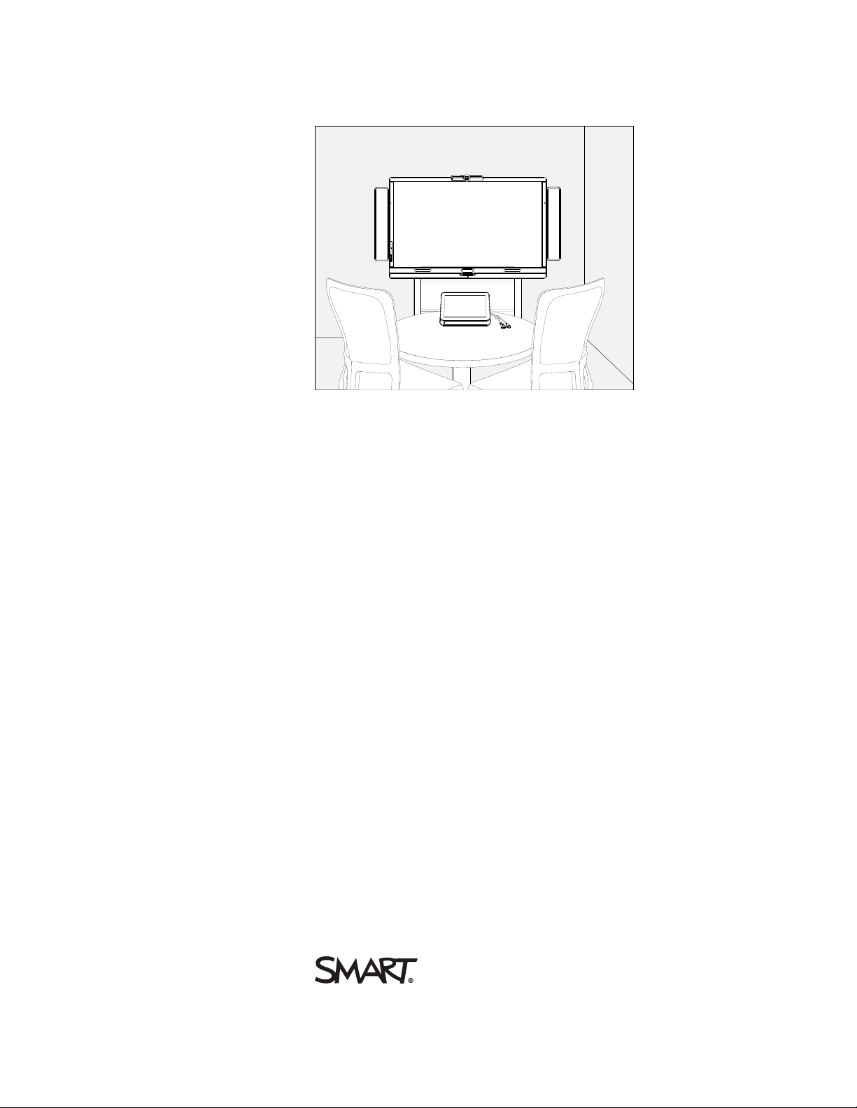
Your SMARTRoomSystem features one or two SMARTBoard® interactive flat panels, a Lync
appliance, a tabletop console, a high-definition camera, microphones, speakers and a video
connection harness for use with an optional guest laptop.
Using the installed Lync Room System software, you can start a meeting and connect with other
individuals or meeting rooms with a single tap on the console or the interactive flat panels. You can
write or draw on the interactive flat panels using the whiteboard feature, connect an optional guest
laptop to share its screen and share files with connected individuals and meeting rooms in real time.
Features
Your room system includes the following features.
Integration with Lync
The SMARTRoomSystem integrates with your organization’s existing Lync infrastructure, enabling
users to schedule meetings, remotely join meetings, and share PowerPoint files using the Lync client
software already installed on their computers.
Simple startup
After the room system turns on, the console and the interactive flat panels show the meeting room’s
schedule, including when the meeting room is booked and when it’s available. Users can start a
scheduled meeting by pressing the meeting’s block in the schedule on either the console or the
interactive flat panels. Lync Room System software enables users to connect to remote participants
and shares video and audio.
Alternatively, users can start ad hoc meetings or whiteboard sessions with a single press of the
console or interactive flat panels.
Automatic sharing of video and audio
When users start or join meetings, the room system shares video and audio automatically without
requiring any manual setup on the users’ part. The room system’s high definition camera,
microphones and speakers facilitate users’ communication during the meeting.
Collaboration
Using Lync Room System software’s whiteboard feature, users can write or draw notes on the
interactive flat panels, automatically sharing with remote participants. Users can also write or draw
over MicrosoftPowerPoint® files attached to the scheduled meeting as well as connect their laptops
to share the laptop screens.
2 smarttech.com/kb/170450
Page 9
C H A P T E R 1
Welcome
Presence detection
Each interactive flat panel has two presence detection sensors on its frame that can detect people up
to 16' (5 m) away. When the sensors detect people in the meeting room, the room system turns on.
When the sensors no longer detect people in the meeting room, the room system enters Standby
mode.
Components
Your room system consists of the following major components:
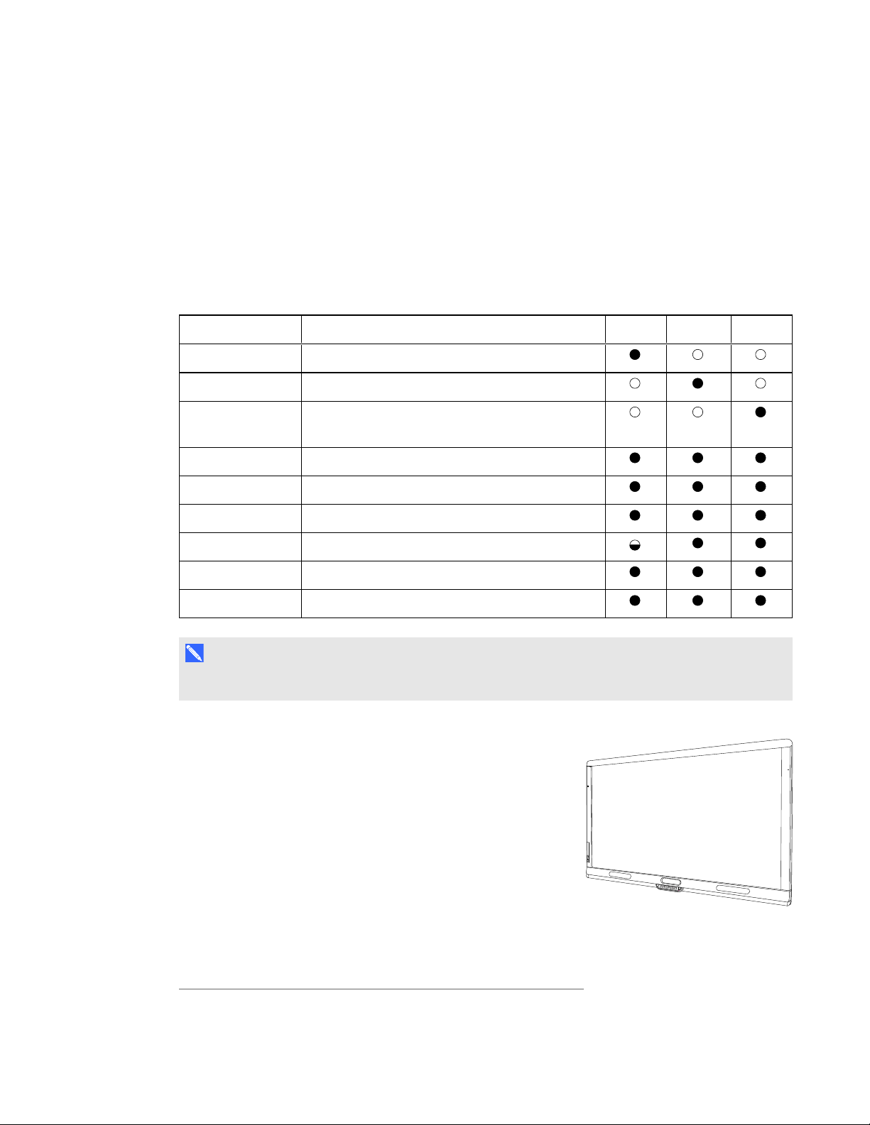
Part no. Description Small Medium Large
SBID 8070i-G4 SMARTBoard 8070i-G4 interactive flat panel
SBID 8084i-G4 SMARTBoard 8084i-G4 interactive flat panel
SBID 8070i-G4
(×2)
SMARTBoard 8070i-G4 interactive flat panel
(×2)
AM70-L Lync appliance
CP311 Console
CAM301 Camera
MIC500 Table microphones
CSR500 Speakers
1019403 Video connection harness for guest laptops
N O T E
Other, minor components are documented elsewhere in this guide.
SMARTBoard interactive flat panels
SMARTBoard interactive flat panels feature SMART’s proprietary
DViT® (DigitalVisionTouch) technology on a 16:9 LCD screen
with e-LED backlight. DViT technology enables users to do the
following:
*
l Interact with content by pressing it with their fingers
l Write digital ink on the digital whiteboard or on a shared
PowerPoint file using their fingers or one of the provided pens
l Erase digital ink using their fists, their palms or the provided
eraser
*
Included in the table microphone upgrade kit
3 smarttech.com/kb/170450
Page 10
C H A P T E R 1
Welcome
During a meeting, the interactive flat panels show video, shared PowerPoint files, and video input
from optionally connected laptops. In addition, users can use the whiteboard feature to record notes
and share them with others.
For information on which interactive flat panel model is included with your room system and the
differences between these models, see Comparing small, medium and large rooms on page 6.
Lync appliance
The Lync appliance includes Lync Room System software as well as SMARTProductDrivers. Lync
Room System software enables users to start, join and facilitate meetings and connect with others
through your organization’s Lync infrastructure. SMARTProductDrivers enables the touch features
of the interactive flat panels and the operation of the all components in the room system.
The Lync appliance is installed in a slot on the bottom of the interactive flat panel.
N O T E
In large rooms, the Lync appliance is installed on the left interactive flat panel.
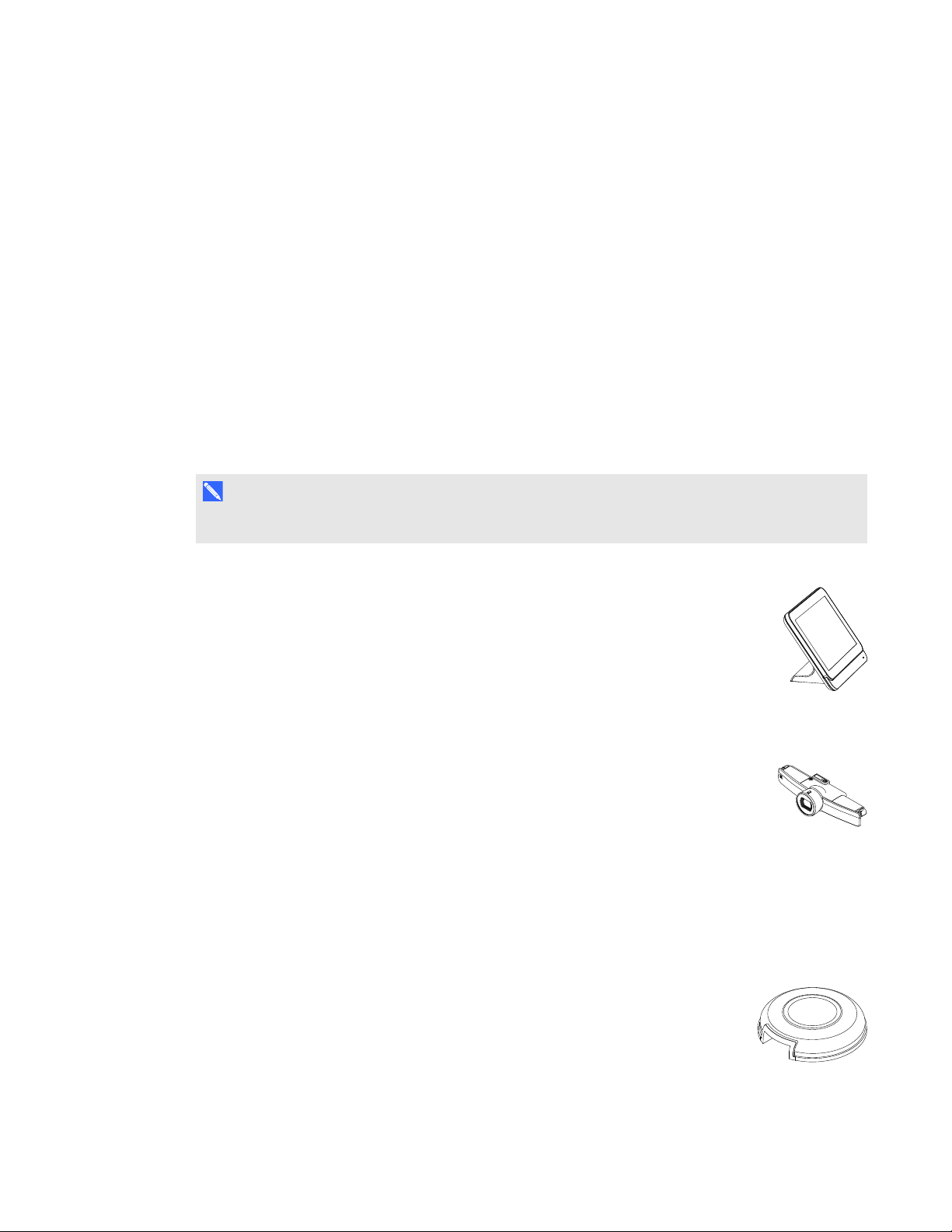
Console
The console is the room system’s primary display. It enables users to access and
control the features of Lync Room System software during their meetings.
The console is typically located on the meeting room table. Like the interactive flat
panels, the console features a 16:9 LCD screen with touch technology, enabling users to
interact with buttons and other controls by pressing them.
Camera
The high definition camera automatically captures room video during meetings. Users
can temporarily stop the video or shutter the camera for privacy purposes.
In most meeting rooms, digital pan, tilt and zoom (DPTZ) and the camera’s 109° field of
view ensure all meeting participants are captured regardless of where they are in the meeting room.
The camera is installed on the top of the interactive flat panel in small and medium rooms or between
the interactive flat panels in large rooms.
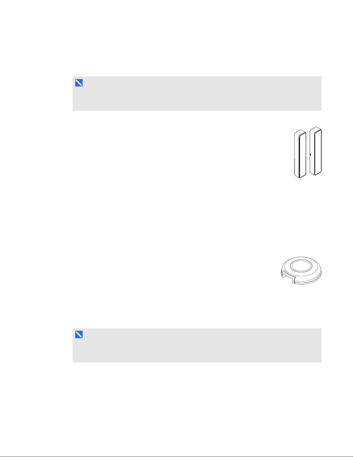
Microphones
The microphones automatically capture audio during meetings. Users can
temporarily mute the microphones for privacy purposes.
4 smarttech.com/kb/170450
Page 11
C H A P T E R 1
Welcome
Depending on your room system, the microphones either are integrated with the camera or are
separate units that are typically located on the meeting room table.
N O T E
Large and medium rooms come with two table microphones. You can purchase additional table
microphones (see Table microphones on the next page).
Speakers
The speakers transmit audio from remote participants during a meeting. The room
system’s audio-processing features eliminate echos and in-room audio feedback.
The speakers are installed on either side of the interactive flat panels.
Video connection harness for guest laptops
The video connection harness enables users to connect their laptops to the room system using either
VGA or HDMI connectors. When a user connects his or her laptop, the laptop’s video output appears
on an interactive flat panel and is shared with remote participants.
The video connection harness’s connectors are typically located on the meeting room table.
Table microphone upgrade kit
A table microphone upgrade kit is available for room systems for small rooms. This
upgrade kit enables you to use table microphones rather than the camera-integrated
microphones for specialized or challenging room configurations. The upgrade kit
includes two table microphones, an audio processor and accompanying cables.
Accessories
Accessories for the SMARTRoomSystem include the wall stand kit and table microphones.
N O T E
For accessory part numbers and ordering information, refer to the specifications (see Specifications
on page 7).
5 smarttech.com/kb/170450
Page 12
C H A P T E R 1
Welcome
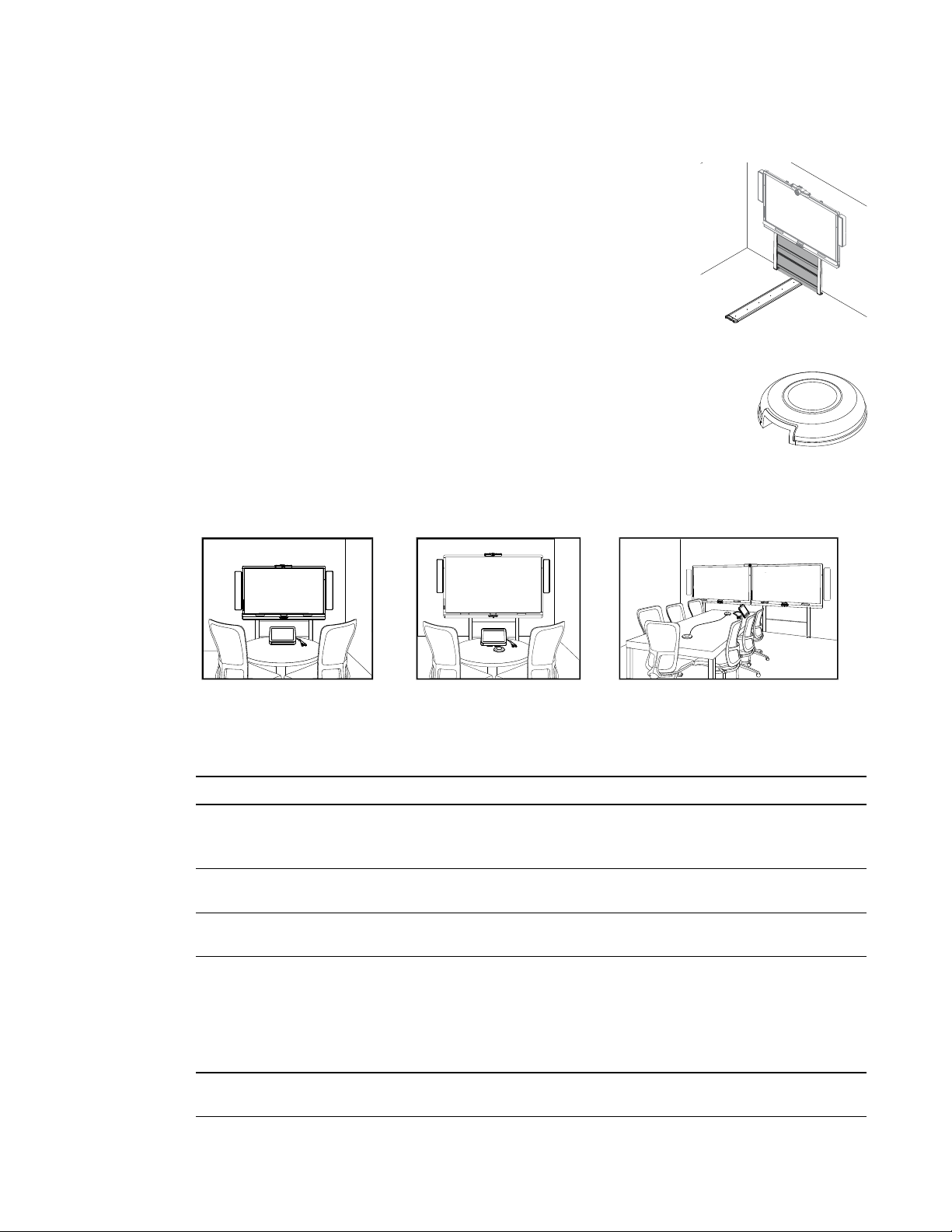
Wall stand kit
The wall stand kit includes a wall stand for each interactive flat panel in your
room system and the cable raceway. The wall stand transfers some of the
weight from the wall to the floor and is required for metal stud walls that can’t
support the full weight of the interactive flat panel. The cable raceway
covers cables running across the floor from the interactive flat panels to the
meeting room table.
Table microphones
Medium and large rooms come with two table microphones. You can purchase and
connect up to three additional table microphones if needed for a total of up to five
table microphones.
Comparing small, medium and large rooms
The SMARTRoomSystem comes in three sizes:
Small
(SRS-LYNC-S)
Medium
(SRS-LYNC-M)
Large
(SRS-LYNC-L)
The following table presents the key differences between the small, medium and large room sizes:
Small room Medium room Large room
Intended use Small meeting rooms
(approximatelysixpeople)
100 sq. ft. (10 m²)
Display type One SMARTBoard 8070i-G4
interactive flat panel
Display size
(diagonal)
Microphones Integrated with camera
Optional wall
stand kit
70" (178 cm) 84" (213.4 cm) 2 × 70" (2 × 178 cm)
(withoutthe table microphone
upgrade kit)
OR
Table top (with the table
microphone upgrade kit)
WSK-SM WSK-SM WSK-L
Medium meeting rooms
(approximately12 people)
180 sq. ft. (20 m²)
One SMARTBoard 8084i-G4
interactive flat panel
Table top Table top
Large meeting rooms
(approximately16 people)
300 sq. ft. (30 m²)
Two SMART Board 8070i-G4
interactive flat panels
6 smarttech.com/kb/170450
Page 13

C H A P T E R 1
Welcome
N O T E
Other, minor differences between sizes are noted throughout this guide.
About this guide
This guide explains how to set up and maintain your room system. It includes the following
information:
l How to install and configure your room system
l How to use your room system’s basic features
l How to maintain your room system for years of use
l How to troubleshoot issues with your room system
l How to remotely manage your room system
This guide in intended for individuals who are responsible for installing and maintaining room systems
in their organizations. Other documentation and resources are available for individuals who use room
systems.
Other documentation and resources
In addition to this guide, there are resources for individuals who install, maintain and use room
systems.
Specifications
Your room system’s specifications define the product’s dimensions, weights, recommended
operating and storage temperatures, power requirements and consumption and other important
information for installation and maintenance.
Document Link
SMARTRoomSystem for Lync for small rooms specifications smarttech.com/kb/170449
SMARTRoomSystem for Lync for medium rooms specifications smarttech.com/kb/170448
SMARTRoomSystem for Lync for large rooms specifications smarttech.com/kb/170447
SMARTRoomSystem for Lync wall stand kit specifications
7 smarttech.com/kb/170450
smarttech.com/kb/170526
Page 14

C H A P T E R 1
Welcome
Installation instructions
Your room system comes with a hardware selection guide that explains which mounting hardware to
use for your room’s wall type and a quick start guide that explains how to install the room system
hardware. In addition, the optional wall stand and raceway include their own installation guides. If you
misplaced any of these installation instructions, you can download PDF versions.
Document Link
SMARTRoomSystem for Lync hardware selection guide smarttech.com/kb/170464
SMARTRoomSystem for Lync for small rooms quick start guide smarttech.com/kb/170470
SMARTRoomSystem for Lync for medium rooms quick start guide smarttech.com/kb/170467
SMARTRoomSystem for Lync for large rooms quick start guide smarttech.com/kb/170468
SMARTRoomSystem for Lync wall stand installation guide smarttech.com/kb/170466
SMARTRoomSystem for Lync cable raceway installation guide smarttech.com/kb/170465
SMARTRoomSystem for Lync table microphone upgrade kit
installation guide
smarttech.com/kb/170560
Deployment and remote management instructions
Microsoft provides documentation on how to deploy Lync software and remotely manage Lync Room
System software using Lync Infrastructure Environment Administrator tools such as the Lync control
console and SCOM. See microsoft.com/en-us/download/details.aspx?id=29256 for this
documentation.
User documentation and training
Lync Meeting Room software includes a tutorial that explains how to use the software. To open the
tutorial, press the OpenTutorial button on the interactive flat panels.
The SMART training website (smarttech.com/training) includes an extensive library of training
resources you can refer to when learning how to use your room system.
Knowledge base
The Support center (smarttech.com/support) includes a knowledge base that you can refer to when
performing maintenance on your room system or troubleshooting issues with your room system.
8 smarttech.com/kb/170450
Page 15

Chapter 2
hardware
This chapter is intended for installers. Before they install the room system’s hardware, installers
should read this chapter along with the hardware installation instructions (see Installation instructions
on page 8) included with the room system.
W A R N I N G
Improper installation of your room system’s hardware can result in personal injury and product
damage.
Before installing your room system’s hardware, do the following:
l Review the room temperature and humidity requirements in the room system’s specifications
(see Specifications on page 7).
l Save all product packaging so that it’s available if you need to transport the room system at a
later date.
N O T E
If the original packaging isn’t available, you can purchase new product packaging from your
authorized SMART reseller (smarttech.com/where).
9 smarttech.com/kb/170450
Page 16
C H A P T E R 2
Installing your room system’shardware
l Ensure the wall can support the weight of the room system.
Room Weight (lb.) Weight (kg)
Small 271 123
Medium 312 141.6
Large 520 236
N O T E S
o
Refer to local building codes to confirm that the wall can support the above weights.
o
Refer to the hardware selection guide for the recommended hardware for your wall type
(see Installation instructions on page 8).
l Choose an appropriate location for the room system:
o
Do not install the room system in a location where a door or gate could hit it.
o
Do not install the room system in an area where it will be subjected to strong vibrations or
dust.
o
Do not install the room system where the main power supply enters the building.
o
Ensure adequate ventilation or provide air conditioning around the room system so that heat
can flow away from the unit and the mounting equipment.
o
If you mount the room system in a recessed area, leave at least 4" (10 cm) of space
between the room system and the recessed walls to enable ventilation and cooling.
l Install the room system so that its center aligns with the center of the meeting room table. This
ensures the meeting room table appears in the center of the camera’s field of view.
l Install the room system so that the interactive flat panels are the appropriate distance from the
floor.
Distance Small room Medium room Large room
From the floor to the bottom of the
32" (81.4 cm) 29 1/2" (74.9 cm) 32" (81.4 cm)
interactive flat panel
From the floor to the bottom of the
38 1/8" (97 cm) 35 3/8" (89.9 cm) 38 1/8" (97 cm)
active display area
10 smarttech.com/kb/170450
Page 17

Chapter 3
software
Before configuring your room system’s software 11
Turning on your room system for the first time 12
Logging on and configuring the displays 16
Configuring Lync Room System software 17
Checking the status of the Lync Room System software productkey 19
Configuring SMARTSettings 19
Making a test call 21
After completing the hardware installation, you must turn on the room system for the first time and
then configure its software.
I M P O R T A N T
This chapter is intended for IT administrators responsible for configuring the room system’s
software.
Before configuring your room system’s software
Before configuring your room system’s software, ensure the following prerequisites are in place:
l Your organization has implemented Lync 2013, and the Lync infrastructure is functioning.
l A Lync room account has been set up for the room system on the domain, on the Microsoft
Exchange server and on the Lync Server.
11 smarttech.com/kb/170450
Page 18
C H A P T E R 3
Configuring your room system’ssoftware
l You have the necessary information to connect the room system to the Lync Server, including
the following:
o
IP addresses for DNS servers (if not configured automatically from the network via DHCP)
o
Administrator user name and password to be applied to the room system
o
Lync appliance computer name for network presence
o
Lync account name and password for the room system
o
SIP URI address
l A USB mouse and keyboard are connected to the Lync appliance for use during the software
configuration.
Turning on your room system for the first time
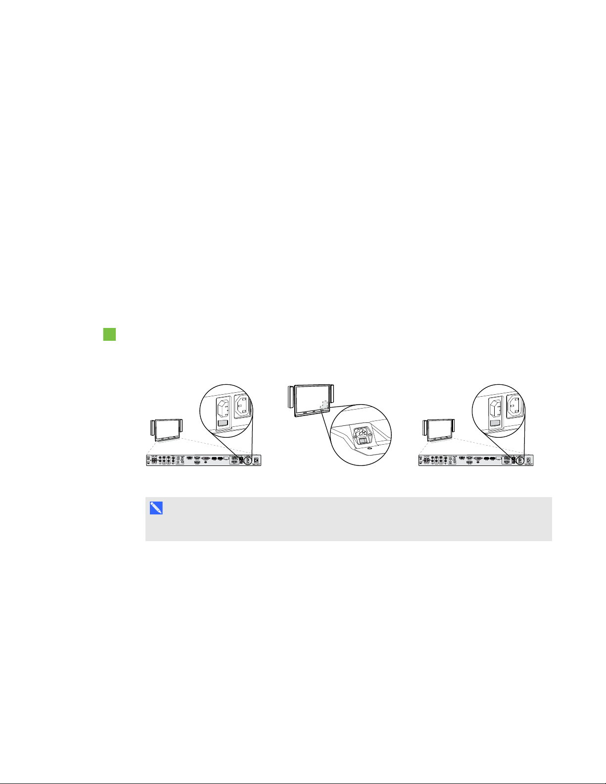
To turn on your room system for the first time
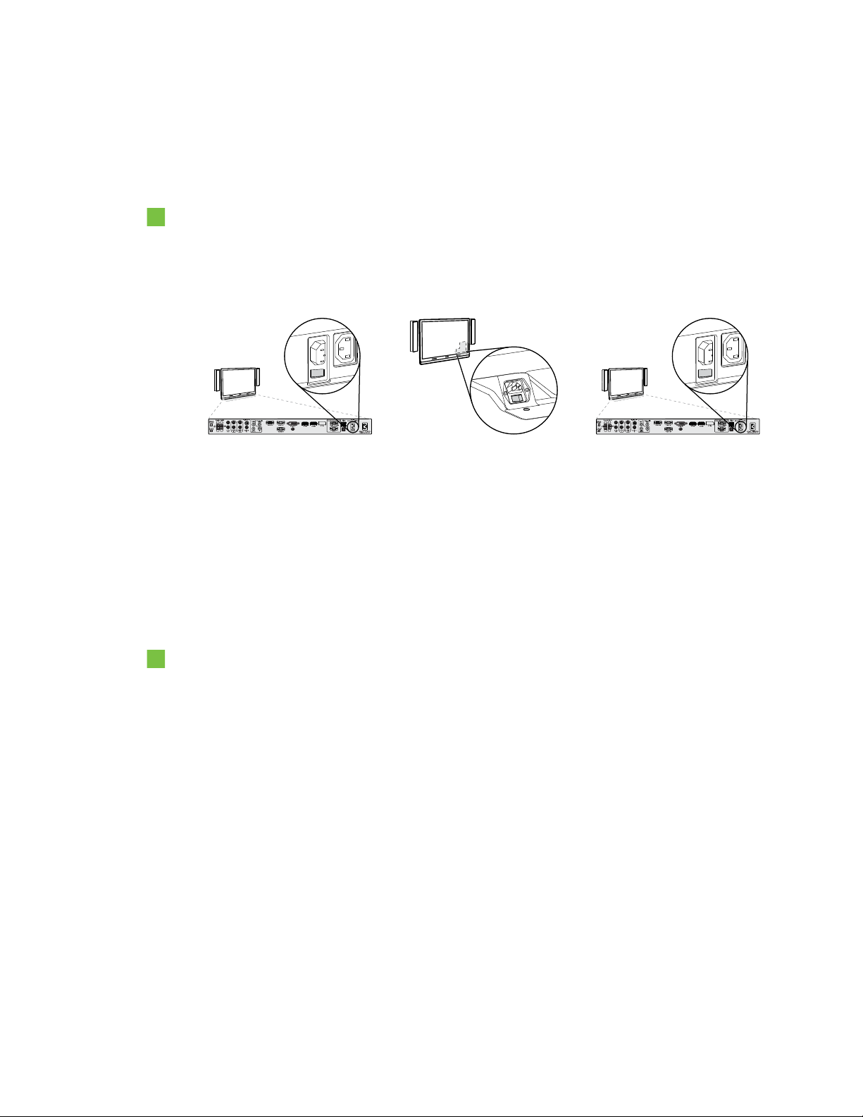
1. Turn on the room system using the power switch located on the bottom of the interactive flat
panel.
Small room Medium room Large room (×2)
N O T E
In large room installations, turn on both interactive flat panels.
12 smarttech.com/kb/170450
Page 19

C H A P T E R 3
Configuring your room system’ssoftware
2.
Press the Input Select button on the interactive flat panel’s front control panel until the input
source is HDMI3/PC.
N O T E
In large room installations, set the input source to HDMI3/PC for both interactive flat panels.
The Lync appliance starts and completes the first-run installation process. During this process,
the Lync appliance restarts several times.
N O T E
This process takes time to complete. During this process, displays might not change content
or might appear blank for several minutes.
13 smarttech.com/kb/170450
Page 20
C H A P T E R 3
Configuring your room system’ssoftware
3. Configure the interactive flat panels’ on-screen display menus:
Room Procedure
Small (without
the table
microphone
upgrade kit)
Small (with the
table microphone
upgrade kit)
Medium
Press MENU on the interactive flat panel’s remote control.
a.
Press the down arrow until you select the SETUP menu, and then
b.
press SET.
Press the down arrow until you select Lync®ROOMRESET, and
c.
then press SET.
Press MENU, press the up arrow until you select the AUDIO menu,
d.
and the press SET.
Press the down arrow until you select AUDIOINPUT, press SET and
e.
then select HDMI3/PC ANALOG.
Press MENU until the on-screen display menu closes.
f.
Press MENU on the left interactive flat panel’s remote control.
a.
Press the down arrow until you select the SETUP menu, and then
b.
press SET.
Press the down arrow until you select Lync®ROOMRESET, and
c.
then press SET.
Press MENU until the on-screen display menu closes.
d.
Press MENU on the interactive flat panel’s remote control.
a.
Press the down arrow until you select the OPTION menu, and then
b.
press OK.
Press the down arrow until you select Lync®RoomReset, and then
c.
press OK.
Press MENU until the on-screen display menu closes.
d.
Large
Press MENU on the left interactive flat panel’s remote control.
a.
Press the down arrow until you select the SETUP menu, and then
b.
press SET.
Press the down arrow until you select Lync®ROOMRESET, and
c.
then press SET.
Press MENU until the on-screen display menu closes.
d.
Repeat steps a to d for the right interactive flat panel.
e.
N O T E
Completing the above steps configures the interactive flat panels’ USB-video mapping, audio
settings, presence detection settings and other settings for use with SMARTRoomSystems.
In addition, completing the above steps disables the volume and input select controls on the
interactive flat panels’ front control panels.
4. Continue to the next procedure.
14 smarttech.com/kb/170450
Page 21

C H A P T E R 3
Configuring your room system’ssoftware
To configure Lync Room System software first-run installation settings
1. Select your language, and then click Next.
2. Select your country or region, time and currency preference, and keyboard layout, and then click
Next.
3. Type a user name for the administrator account and a computer name for the Lync appliance,
and then click Next.
N O T E S
o
Follow your organization’s standard for assigning user names and computer names.
o
The administrator account’s user name is usually “admin”.
4. Type a password for the administrator’s account and a hint for that password, and then click
Next.
I M P O R T A N T
You must provide the administrator account’s user name and password whenever you change
the room system’s configuration or troubleshoot issues. If you forget the administrator
account’s user name and password, you are unable to reset it without resetting the room
system to the factory image and then configuring the software again. Therefore, record the
administrator account’s user name and password in a safe place.
5. Select your time zone, specify the current date and time, and then click Next.
The Lync appliance restarts several times. When the basic configuration process is complete, a
screen prompting for the administrator account’s password appears.
N O T E
After the Lync appliance shuts down and starts again for the first time, it might prompt you for
a password or it might log in by itself. In either case the Lync appliance will shut down and
start again.
6. Continue to the next procedure.
15 smarttech.com/kb/170450
Page 22

C H A P T E R 3
Configuring your room system’ssoftware
Logging on and configuring the displays
To log on and configure the displays
1. Type the administrator account’s user name and password that you created in the previous
procedure, and then press ENTER.
The Lync appliance’s desktop and the SMART end user license agreement appear.
2. Read the SMART end user license agreement, and then click Accept.
The Conferencing Microphone Configuration dialog box appears.
3. If you’re configuring the software for a small room without the table microphone upgrade kit,
select Usethecamera microphone, and then click OK.
OR
If you’re configuring the software for a small room with the table microphone upgrade kit, a
medium room or a large room, select Use the table microphone, and then click OK.
I M P O R T A N T
o
You are unable to change this setting later, so ensure you select the correct option.
o
If you originally configured the software for a small room without the table microphone
upgrade kit and subsequently want to configure it for a small room with the table
microphone upgrade kit, you must set the room system to its factory defaults (see
Resetting the room system to factory defaults on page 71).
A dialog box prompting you to check the display settings appears.
4. Click OK.
Control Panel opens, and a second dialog box appears.
16 smarttech.com/kb/170450
Page 23
C H A P T E R 3
ConsoleLeft interactive flat panel Right interactive flat panel
(large rooms only)
1366 × 768
1920 × 1080 (1080p)1920 × 1080 (1080p)
Configuring your room system’ssoftware
5. Configure the displays as follows:
I M P O R T A N T
o
Align the top of all displays as shown in the above diagram.
o
Set the console as the main display by clicking its thumbnail and then selecting
Makethismy main display.
o
Position the console to the right of the interactive flat panels as shown in the above
diagram.
o
You are unable to change these settings later, so ensure you configure the displays
correctly.
T I P
To determine which display is which, press Identify. Each display’s number appears briefly on
the display.
6. Click OK in Control Panel, and then click OK in second dialog box.
The Lync appliance checks the display configuration:
o
If there are major errors, a dialog box appears. Repeat this procedure to correct the errors.
o
If there are no major errors, Lync Room System software starts. Continue to the next
procedure.
Configuring Lync Room System software
N O T E
The following procedure documents SMART’s recommended configuration of Lync Room System
software for a typical Lync infrastructure setup. Refer to the MicrosoftLync Room System
Deployment Guide (microsoft.com/en-us/download/confirmation.aspx?id=39274) for detailed
deployment information.
17 smarttech.com/kb/170450
Page 24

C H A P T E R 3
Configuring your room system’ssoftware
To configure Lync Room System software
1. Read the end user license agreement, and then click Accept.
The Lync Admin Console appears.
2. Click Lync Settings, and then set the following controls:
Control Procedure
User Name Type the room system’s full domain account name
(forexample,yourdomain\room1).
SIP URI Type the room system’s SIP URI (for example,
room1@yourdomain.com).
Password Type the room system’s password.
Proxy Credentials Select Use Lync Account credentials.
Windows Event
Optionally, enable this feature to assist with troubleshooting.
Logging
3. Click System Settings, and then click Network Connections.
Control Panel appears.
4. Right-click Local Area Connection, and then select Properties.
The Local Area Connection Properties dialog box appears.
5. Select Internet Protocol Version 4 (TCP/IPv4), and then click Properties.
The Internet Protocol Version 4 (TCP/IPv4) Properties dialog box appears.
6. Select Obtain DNS server address automatically.
OR
Select Use the following DNS server addresses, and then type your domain’s DNS server
addresses in the PreferredDNSserver and AlternateDNSserver boxes.
7. Select Validate settings upon exit, and then click OK.
8. Click Password Renewal, and then disable Auto-Renew Password.
9. Continue to the next procedure.
18 smarttech.com/kb/170450
Page 25

C H A P T E R 3
Configuring your room system’ssoftware
Checking the status of the Lync Room System
software productkey
To check the status of Lync Room System software product key
1. Click OEM Settings, and then click SRS Licensing Tool.
2. Click Check Status.
If your organization has a Lync Room System software product key distributed by a key
managed service (KMS) server, the Status box indicates that the room system is licensed.
Otherwise, the Status box indicates that the room system isn’t licensed.
3. If the room system is licensed, continue to the next procedure.
OR
If the room system isn’t licensed, type the multiple activation key (MAK) provided by Microsoft in
the MAK key box, click Activate Key, and then continue to the next procedure.
Configuring SMARTSettings
To calibrate and orient touch on the interactive flat panels
1. Click OEM Settings, and then click SMART Board Settings.
SMARTSettings appears.
2. Click Connection Wizard.
The SMART Connection wizard appears. The wizard detects your room system’s SMART
interactive products.
N O T E
SMART interactive products include the interactive flat panels and the console.
19 smarttech.com/kb/170450
Page 26
C H A P T E R 3
Configuring your room system’ssoftware
3. For each interactive flat panel, do the following:
a. Select the interactive flat panel from the list, and then click Next.
b. Select Product is being set up for the first time, and then click Next.
The calibration screen appears on the selected interactive flat panel.
N O T E
If the calibration screen doesn’t appear on the selected interactive flat panel, move it to
the selected interactive flat panel by pressing the spacebar on the keyboard or the Orient
button on the interactive flat panel’s color select module.
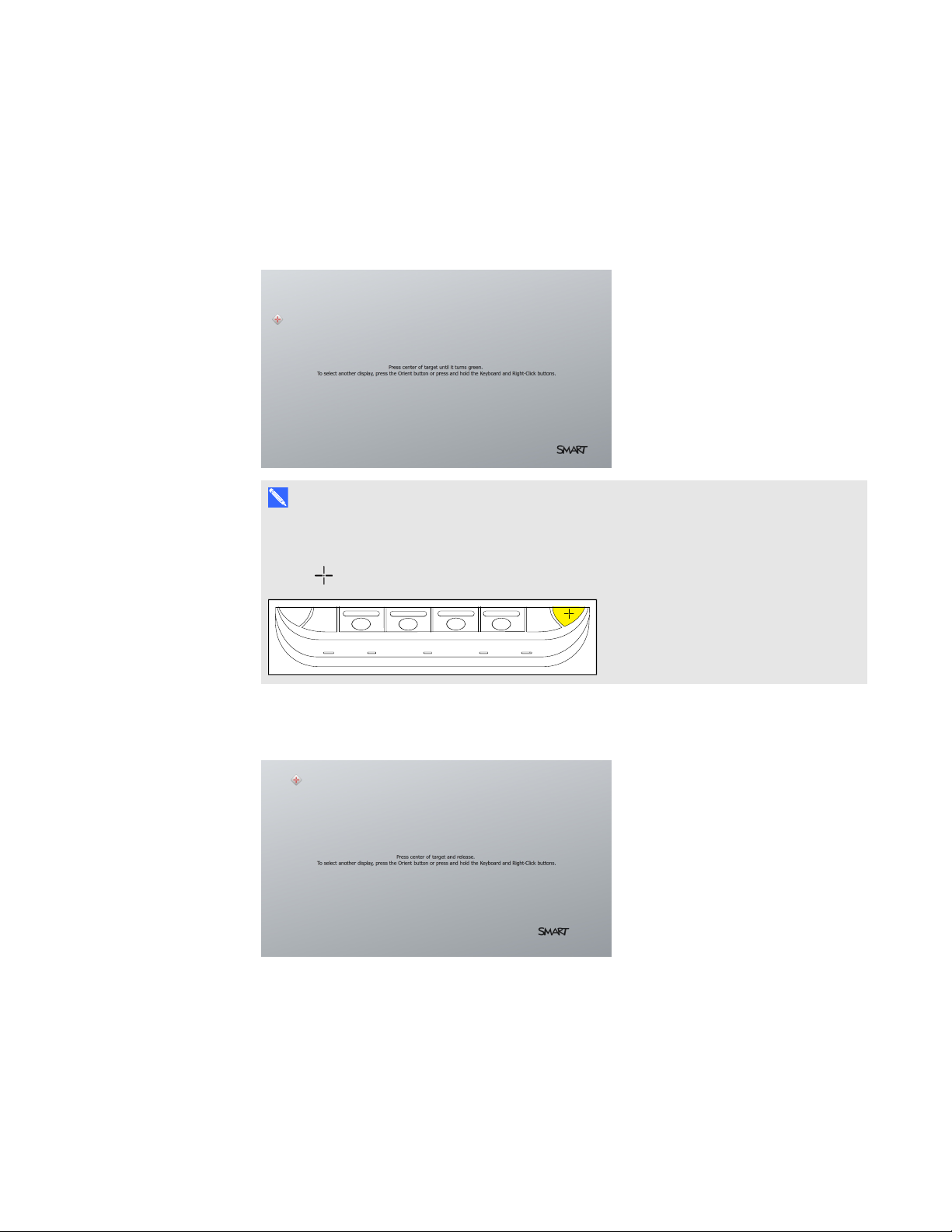
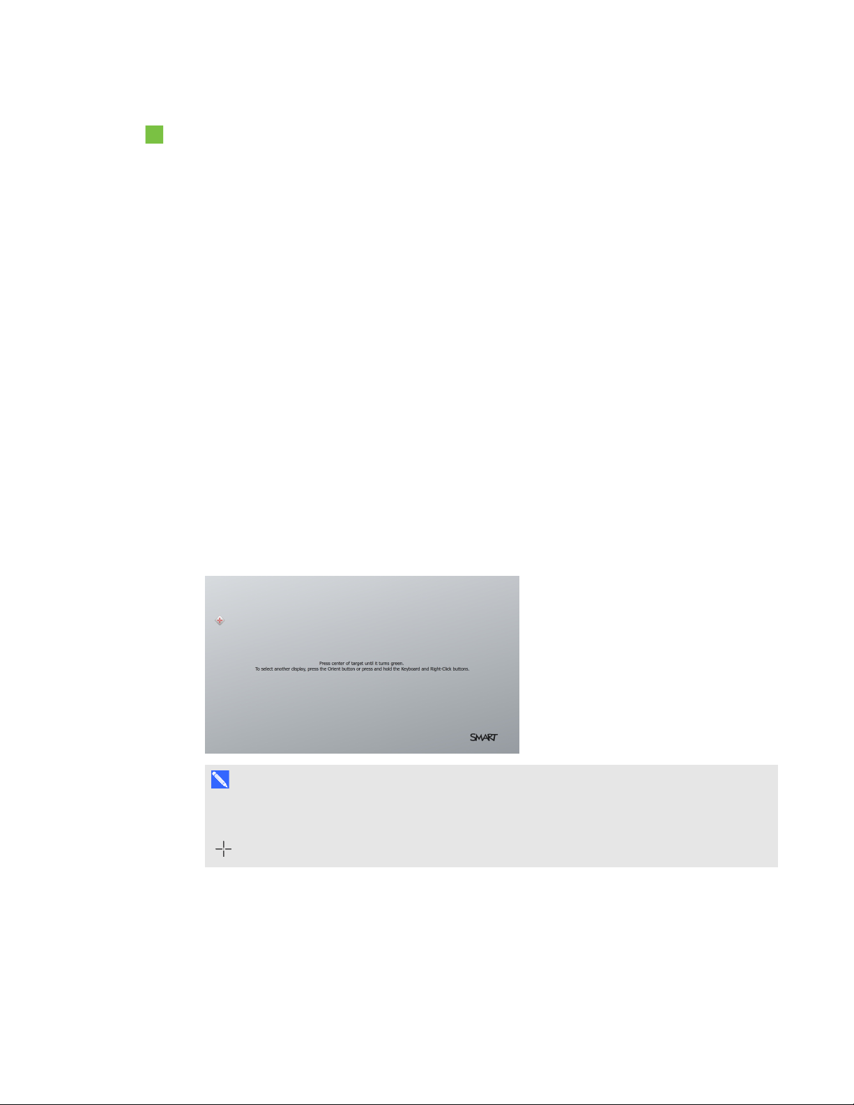
c. Calibrate the interactive flat panel following the on-screen instructions.
The orientation screen appears on the selected interactive flat panel.
20 smarttech.com/kb/170450
Page 27

C H A P T E R 3
Configuring your room system’ssoftware
d. Orient the interactive flat panel following the on-screen instructions.
N O T E S
o
If you touch a target in either the calibration screen or the orientation screen but
aren’t advanced to the next target, press the spacebar or the Orient button to
move to the next interactive flat panel and try again.
o
You don’t need to calibrate or orient the console.
4. Continue to the next procedure.
To optimize the camera and complete the software configuration
1. If SMARTSettings isn’t open from the previous procedure, click OEM Settings, and then click
SMART Board Settings.
SMARTSettings appears.
2. Click SMARTHardware Settings.
3. Click the camera icon, and then select Hardware Info & Settings from the drop-down list.
4. Click Preview.
The SMART Camera window opens.
5. Set the pan, tilt and zoom as appropriate for the meeting room’s size, select the mains power line
frequency for your country (50 Hz or 60 Hz), and then click OK.
N O T E
Digital pan and tilt options are available only when the camera is zoomed in.
6. Click OK.
SMARTSettings closes.
7. Continue to the next procedure.
Making a test call
To make a test call
1. Click Lync Settings, and then click Make a Test Call.
Lync Room System software makes a test call.
2. If the audio is too loud or too quiet, adjust the audio settings in the Lync Settings tab.
21 smarttech.com/kb/170450
Page 28

C H A P T E R 3
Configuring your room system’ssoftware
3. If adjusting the audio settings in the previous step didn’t resolve your audio issues, do the
following:
a. Click System Settings, and then clickNetwork Connections.
Control Panel appears.
b. Click Control Panel in the address bar.
c. Click Hardware and Sound, and then click Sound.
The Sound dialog box appears.
d. Click the Playback tab.
e. Right-click each playback device and select Test to determine which device is working.
f. Right-click the working playback device, and then select Set as Default Device.
g. Right-click all other playback devices, and then select Disable.
h. Click OK in the Sound dialog box, and then click OK in Control Panel.
4. Make another test call.
5. Click Apply & Restart.
The Lync appliance restarts in user mode.
N O T E
If the Lync appliance starts in administrator mode, click Apply & Restart again to shut down
and start the Lync appliance in user mode.
22 smarttech.com/kb/170450
Page 29
Chapter 4
Scheduling meetings 23
Turning on your room system 24
Starting meetings and whiteboard sessions 25
Managing meetings using the console 26
Presenting content during meetings 28
Presenting computer screens 29
Presenting files 29
Using the whiteboard feature 30
Ending meetings 30
This chapter provides an overview of how users can schedule and conduct a meeting using your
SMARTRoomSystem and Lync Room System software.
Scheduling meetings
Using MicrosoftOutlook® on their personal computers, users can schedule Lync meetings and book
the SMARTRoomSystem as a resource.
To schedule a new Lync meeting
1. Start Outlook, and then click Calendar.
2. Click Home, and then click New Lync Meeting.
N O T E
For users with older versions of Lync software, this button is labeled New Online Meeting.
A new Lync meeting opens.
3. Select a date and time for the meeting, type a subject and details, and then add participants and
resources (including the room system).
23 smarttech.com/kb/170450
Page 30

C H A P T E R 4
Using your room system
4. If appropriate, make the meeting private so that participants must enter a password to join:
a. Click Meeting Options.
The Lync Meeting Options dialog box appears.
b. Click Permissions, and then select A new meeting space (I control permissions).
c. Select who to permit as participants, who to permit as presenters, and any limitations on
presenters.
d. Click OK.
5. Send the meeting invitation to the participants and resources.
To convert an existing meeting to a Lync meeting
1. Start Outlook, and then click Calendar.
2. Locate the meeting in the calendar, and then double-click it.
The meeting opens.
3. Click Appointment, and then click Lync Meeting.
N O T E
For users with older versions of Lync software, this button is labeled Online Meeting.
4. Add the room system as a resource.
5. Send the meeting update to the participants and resources.
Turning on your room system
Your room system’s interactive flat panels have two presence detection sensors on their frames that
can detect people up to 16' (5 m) away when the room system is in Standby mode.
When the sensors detect motion in the room, the room system turns on. If presence detection is
disabled, you can manually turn on the room system by pressing the Power/Standby button on the
front control panel of each interactive flat panel.
24 smarttech.com/kb/170450
Page 31

C H A P T E R 4
Using your room system
Starting meetings and whiteboard sessions
After the room system turns on, the interactive flat panels and the console show the room system’s
schedule as a set of squares:
l When the room system is booked for a meeting, the meeting’s details and Join appear in the
square.
l When the room system is available, Free appears in the square.
N O T E
If the room system’s schedule doesn’t appear or update correctly, there might be an issue with the
connection between the Lync Room System software and Microsoft Exchange server (see
Resolving software issues on page 53).
Users can join a scheduled meeting when the room system is booked, or they can create an ad hoc
meeting or an ad hoc whiteboard session when the room system is available.
To join a scheduled meeting
1. Press the meeting’s square on either the interactive flat panels or the console.
N O T E
The schedule shows only the Lync meetings to which the room system has been added as a
resource. If a meeting doesn’t appear as a square in the schedule, convert the meeting to a
Lync meeting and add the room system to the meeting as a resource (see Scheduling
meetings on page 23).
2. If the meeting is private, type the appropriate sign-in address, user name and password in the
text boxes, and then click Join.
The console shows a set of tabs for managing the meeting (see Managing meetings using the
console on the next page). The interactive flat panels show up to five connected participants’
videos in a gallery.
To create an ad hoc meeting
1. Press Meet Now on the console.
2. Add participants to the meeting.
25 smarttech.com/kb/170450
Page 32

C H A P T E R 4
Using your room system
3. Press Start Meeting.
The console shows a set of tabs for managing the meeting (see Managing meetings using the
console below). The interactive flat panels show all connected participants’ videos in a gallery.
T I P
Alternatively, if the Lync infrastructure supports connecting through POTS, press Dial Pad
and use the dial pad to call a person using the room system. To convert the audio call into a
video meeting, press StartVideo and then press InviteMorePeople.
To create an ad hoc whiteboard session
1. Press Start Whiteboard on the console or on one of the interactive flat panels.
2. Write or draw digital ink (see Using the whiteboard feature on page 30).
3. Press Email Whiteboard when done to e-mail the whiteboard file.
Managing meetings using the console
The console enables users to manage the meeting and the room system features. The user who
organized the meeting typically sits in front of and operates the console during the meeting.
During the meeting, users can show and use the following tabs on the console:
Tab Contents Actions
Content The name of the participant
who is currently presenting
and the content uploaded to
the meeting including
PowerPoint files and
whiteboard sessions
Press a content item, and then click
l
StartPresenting to present the item.
Press StopPresenting when done.
l
26 smarttech.com/kb/170450
Page 33

C H A P T E R 4
Using your room system
Tab Contents Actions
Participants A list of all participants in the
meeting
Display Display options for the room
system’s interactive flat
panels
Press a participant’s name and then select
l
the appropriate option from the menu:
o
Mute and unmute the participant’s
audio
o
Pin the participant’s video to the
gallery so that it’s always visible
o
Lock or unlock the spotlight on the
participant
o
Remove the participant from the
meeting
Press Invite More People to invite
l
additional participants.
Press Mute Audience to mute all
l
participants’ audio except for the participant
who is currently presenting.
In small and medium rooms, select from
l
one of the following options:
o
Gallery & Content to show the gallery
and shared content
o
Gallery to show only the gallery
o
Presentation to show only shared
content
o
Speaker to show only the presenting
participant’s video
o
Speaker & Content to show the
presenting participant’s video and
shared content
In large rooms, select from one of the
l
following options:
o
Gallery & Content to show the gallery
on one interactive flat panel and shared
content on the other interactive flat
panel
o
Speaker to show the presenting
participant’s video on one interactive
flat panel and shared content on the
other interactive flat panel
o
Gallery View to show the gallery
across both interactive flat panels
Enable Preview to show the video from the
l
room system camera.
27 smarttech.com/kb/170450
Page 34

C H A P T E R 4
Using your room system
Tab Contents Actions
IM Instant messages (IMs)
shared during the meeting
Press the input field and then use the
on-screen keyboard to type an IM. All
participants in the meeting can see all IMs.
In addition to the tabs, the console contains a toolbar with the following buttons:
Button Procedure
Stop Video Stop the meeting room’s video.
Hold Call Stop the meeting’s video and mute the audio.
Mute Room Mute the meeting room’s microphones.
Speaker Off Mute the meeting room’s speakers.
Room Volume Move the slider to adjust the volume.
Dial Pad Show a dial pad to use Lync Room System software’s phone features (if the
Lync infrastructure supports a POTS bridge).
New Whiteboard Create a new whiteboard file.
Email Whiteboard E-mail the whiteboard file.
Leave Meeting Disconnect the room system from the Lync meeting (see Ending meetings on
page 30).
Presenting content during meetings
During a meeting, users can present the following:
l Their computer screens
l Files
l A digital whiteboard
N O T E
Remote participants connecting to the meeting through some smart phones and other mobile
devices are unable to view shared computer screens or whiteboard sessions due to limitations of
the Lync client software for those devices.
28 smarttech.com/kb/170450
Page 35

C H A P T E R 4
Using your room system
Presenting computer screens
Users with laptops can connect the laptop harness’s HDMI cable or VGA cable to their laptops to
present their laptops’ video outputs. If the console prompts the user to share the screen, the user
should press Yes.
Alternatively, these users can join the Lync meeting from their laptops’ Lync client software. When
prompted to confirm that they’re in the meeting room, these users should click Yes. Next, they should
click Presentation in Lync software, and then select what they want to share.
N O T E
When remote participants join a meeting and are prompted to confirm that they’re in the meeting
room, they should click No. They can then click Presentation in Lync software and select what
they want to share.
Other participants attending the meeting in person see the user’s computer screen on one of the
interactive flat panels. Remote participants also see the user’s computer screen in real time.
Presenting files
A user who joins the meeting from his or her computer can share files, including PowerPoint files.
To share a PowerPoint file, the user clicks Presentation in Lync software, and then selects
PowerPoint. By default, other users can write or draw over the PowerPoint file but must click
Content and then select TakeOverasPresenter (on the console) or press the arrow buttons and
then press Yes when prompted to take over as the presenter (on interactive flat panels) before doing
so.
N O T E S
l The user sharing the PowerPoint file must select PowerPoint and share the PowerPoint file
(rather than the PowerPoint application) to enable other users to write or draw over the
PowerPoint file.
l The user sharing the PowerPoint file can choose to prevent or allow other writers to write or
draw over the file.
To write or draw digital ink over slides from the interactive flat panels, users can press the mode bar
(up or down arrow), press Annotate, and then write or draw using their finger or one of the interactive
flat panel pens.
Users can also press Enable Media to show any embedded videos in the PowerPoint files.
29 smarttech.com/kb/170450
Page 36

C H A P T E R 4
Using your room system
Using the whiteboard feature
To start a digital whiteboard during a meeting, users can press New Whiteboard on the interactive
flat panels or the console. A new whiteboard session appears on one of the interactive flat panels.
Users can use the interactive flat panel’s pens and eraser to write, draw and erase digital
ink.Alternatively, they can use their fingers to write or draw digital ink and their fists or palms to erase
it.
In addition to writing, drawing and erasing digital ink, users can move digital ink and other objects in
the whiteboard file and create additional whiteboard files.
Remote participants see the whiteboard session in real time and can add their own digital ink notes to
it as part of a collaborative effort.
At the end of the meeting, the users can press Email Whiteboard on the console to e-mail the
whiteboard file.
T I P
If users haven’t started a meeting (see Starting meetings and whiteboard sessions on page 25) but
still want to use the whiteboard feature, they can press StartWhiteboard on the interactive flat
panels or the console.
Ending meetings
At the end of the meeting, users can press Leave Meeting on the console to disconnect the room
system from the Lync meeting. The Lync meeting ends when all participants have left.
30 smarttech.com/kb/170450
Page 37

Chapter 5
Recommended tools 32
Turning off your room system 33
Updating software and firmware 33
Maintaining the interactive flat panels 34
Calibrating the interactive flat panels 34
Orienting the interactive flat panels 36
Cleaning the screens 37
Cleaning the presence detection sensors 38
Cleaning the camera windows and reflective tape 38
Maintaining ventilation 39
Preventing condensation 39
Replacing a pen nib 40
Using the kickstands to access connectors 40
Maintaining the console 41
Maintaining the camera 42
Maintaining the microphones 42
Maintaining the speakers 42
Checking your room system installation 43
Removing and transporting your room system 43
Your room system is designed to require no, or only minimal, cleaning and other maintenance.
If your room system requires cleaning or other maintenance or if your organization mandates periodic
cleaning or other maintenance of its IT infrastructure, follow the instructions in this chapter.
31 smarttech.com/kb/170450
Page 38

C H A P T E R 5
Maintaining your room system
Recommended tools
The following are recommended tools that professional, trained installers and IT specialists should
have available for maintenance and troubleshooting purposes:
Activity Recommended tools
Hardware service
Hardware isolation testing
Paper and pencil
l
Ladder
l
Tape measure
l
Set of screwdrivers, including flat blade, PhillipsNo.1 and
l
PhillipsNo.2
Flashlight
l
Nylon cable ties
l
Cable tie cutter
l
16' 5" (5 m) USB cable
l
16' 5" (5 m) USB cable with mini-B connector
l
16' 5" (5 m) active USB extension cable
l
20' 8" (6.3 m) HDMI cable
l
Functional spare Lync appliance
l
Functional spare console and power supply
l
Functional spare camera kit
l
Functional spare microphone and audio processor kit,
l
includingcables
Functional spare speaker kit, including cables
l
IT access
32 smarttech.com/kb/170450
IT administrator with knowledge of your organization’s Lync
l
infrastructure
SMARTBoard interactive flat panel remote control
l
USB keyboard and mouse
l
Laptop that has Outlook and Lync client software and that is
l
connected to your organization’s Lync infrastructure
Internet access for documentation and other resources
l
(seeOther documentation and resources on page 7)
Alternative audio source, such as a portable music player
l
Page 39
C H A P T E R 5
Maintaining your room system
Turning off your room system
For some maintenance procedures, you need to turn off your room system.
To turn off your room system
1. On the console, press Options, and then press Restart.
2. When the screens are blank or when the SMART logo appears, use the power switches on the
bottoms of the interactive flat panels to turn off the room system.
Small room Medium room Large room (×2)
Updating software and firmware
At a scheduled time each night, your room system checks for updates to its software and firmware
from Windows® Update. It then installs any updates and restarts.
You can also manually check for updates.
To manually check for updates
1. On the console, press Options, and then press Settings.
The Enter your credentials screen appears.
2. Type the room system administrator account’s user name and password in the text boxes, and
then press Authenticate.
The room system restarts.
3. Type the room system administrator account’s user name and password, and then press
ENTER.
The Settings screen appears.
4. Press Web Updates.
33 smarttech.com/kb/170450
Page 40

C H A P T E R 5
Maintaining your room system
5. Press Check Updates and Install.
Lync Room System software checks for and installs any updates.
6. Press Apply and Restart.
Maintaining the interactive flat panels
Complete the following tasks on a regular basis to maintain your room system’s interactive flat
panels:
l Calibrate and orient the interactive flat panels as necessary
l Clean the screen
l Clean the presence detection sensors
l Clean the camera windows and reflective tape
l Maintain ventilation
l Prevent condensation
l Replace pen nibs as necessary
Calibrating the interactive flat panels
Digital cameras in the corners of the interactive flat panels track the position of the pens, eraser and
your finger on the screens, and then send the information to SMARTProductDrivers, which
interprets this information as mouse clicks, digital ink or ink removal in the appropriate location.
Calibration determines the position and angles of the cameras to accurately identify the location of
touches on the interactive flat panels.
Typically, you need to calibrate the interactive flat panels during initial configuration only (see
Configuring SMARTSettings on page 19). However, you might need to calibrate the interactive flat
panels after initial configuration in the following situations:
l Digital ink disappears as users write or draw.
l The environment lighting changes.
I M P O R T A N T
l To calibrate the interactive flat panels, you need the room system administrator account’s user
name and password.
l If an error message appears while you are calibrating the interactive flat panels, contact
SMARTSupport (smarttech.com/contactsupport).
34 smarttech.com/kb/170450
Page 41
C H A P T E R 5
Maintaining your room system
To calibrate an interactive flat panel
1. On the console, press Options, and then press Settings.
The Enter your credentials screen appears.
2. Type the room system administrator account’s user name and password, and then press
Authenticate.
The room system restarts.
3. Type the room system administrator account’s user name and password, and then press
ENTER.
The Settings screen appears.
4. Press OEM Settings, and then press SMART Board Settings.
SMARTSettings appears.
5. Press SMART Hardware Settings.
6. Select the interactive flat panel you want to calibrate.
7. Select Advanced Settings from the drop-down list.
8. Press Calibrate.
The calibration screen appears. This can take a few moments.
N O T E
If the calibration screen doesn’t appear on the selected interactive flat panel, move it to the
selected interactive flat panel by pressing the spacebar on the keyboard or the Orient button
on the interactive flat panel’s color select module.
35 smarttech.com/kb/170450
Page 42

C H A P T E R 5
Maintaining your room system
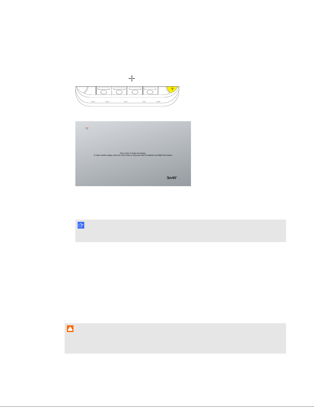
9. Press the red target with the tip of an interactive flat panel pen. Hold the tip at the center of the
target until the target turns green, and then lift the pen.
The target moves to the next location.
I M P O R T A N T
Hold the pen perpendicular to the screen.
N O T E
You can calibrate a target again by pressing the Keyboard button or the Right-click button on
the interactive flat panel’s color select module.
10. Continue pressing targets until the calibration is complete.
A message appears stating that the calibration was successful, and then the orientation screen
appears.
11. Orient the interactive flat panel (see Orienting the interactive flat panels below).
Orienting the interactive flat panels
Typically, you need to orient the interactive flat panels during initial configuration only (see
Configuring SMARTSettings on page 19). However, you might need to orient the interactive flat
panels again if the location of users’ touch is misinterpreted (a pointer appears a distance from the
actual contact or on a different display than the one being touched).
I M P O R T A N T
To orient the interactive flat panels, you need the room system administrator account’s user name
and password. You’re unable to orient the interactive flat panels in user mode.
To orient an interactive flat panel
1. On the console, press Options, and then press Settings.
The Enter your credentials screen appears.
2. Type the room system administrator account’s user name and password, and then press
Authenticate.
The room system restarts.
3. Type the room system administrator account’s user name and password, and then press
ENTER.
The Settings screen appears.
36 smarttech.com/kb/170450
Page 43
C H A P T E R 5
Maintaining your room system
4. Type the room system administrator account’s user name and password in the text boxes, and
then press Authenticate.
The room system restarts, and the Settings screen appears.
5.
Press the Orient button on the interactive flat panel’s color select module.
The orientation screen appears.
6. Use an interactive flat panel pen to press the red targets as they appear. Hold the tip of the pen
at the center of each target, and then lift the pen.
The target moves to the next orientation point.
I M P O R T A N T
Hold the pen perpendicular to the screen.
7. Continue until you’ve pressed all the targets.
The orientation window closes.
8. If this doesn’t correct inaccurate touch control, calibrate the interactive flat panel (see Calibrating
the interactive flat panels on page 34).
Cleaning the screens
Follow these instructions to clean the interactive flat panels’ screens without damaging their
anti-glare coating or other product components.
C A U T I O N
l Do not use permanent or dry-erase markers on the screens. If dry-erase markers are used on
the screens, remove the ink as soon as possible with a lint-free, non-abrasive cloth.
37 smarttech.com/kb/170450
Page 44

C H A P T E R 5
Maintaining your room system
l Do not rub the screens with a dense or rough material.
l Do not apply pressure to the screens.
l Do not use cleaning solution or glass cleaner on the screens, because they can deteriorate or
discolor the screens.
l Avoid touching the reflective tape between the screens and the bezel, and ensure that this
strip stays dry. Damage to this strip affects touch interactivity.
To clean the screens
1. Turn off your room system (see Turning off your room system on page 33), and then disconnect
the power sources for the interactive flat panels.
2. Wipe the screens with a lint-free, non-abrasive cloth.
Cleaning the presence detection sensors
Each interactive flat panel has two presence detection sensors on its frame.The sensors should be
inspected annually for dust and should be cleaned if any obvious dust buildup has occurred.
C A U T I O N
Do not use compressed air, water, chemical agents or cleaning agents to clean the sensors.
To clean the presence detection sensors
Gently wipe the sensors using a clean lint-free cloth.
Cleaning the camera windows and reflective tape
The DViT technology in the interactive flat panels uses four cameras in the corners of the frames and
the reflective material between the screens and the bezels. Excessive dust buildup on the camera
windows or reflective tape can impair touch performance.
These areas should be inspected annually for dust and should be cleaned if any obvious dust buildup
has occurred.
C A U T I O N
l Do not use compressed air to clean the camera windows or borders.
l Do not use water, chemicals or cleaning agents.
38 smarttech.com/kb/170450
Page 45

C H A P T E R 5
Maintaining your room system
l Applying too much pressure when cleaning the tape or cameras can damage the tape and
cameras and cause performance issues or errors.
To clean the camera windows and reflective tape
1. Using a clean lint-free cloth, gently wipe the camera windows in the top corners and the
reflective tape along the top of the interactive flat panel screens.
2. Gently wipe the reflective tape along the sides of the interactive flat panel screens.
3. Gently wipe the camera windows in the bottom corners and the reflective strip across the bottom
of the interactive flat panel screens.
Maintaining ventilation
The interactive flat panels require ventilation to enable the cooling fans to function. Dust buildup in the
ventilation holes compromises cooling and leads to product failure.
l Clean accessible ventilation holes monthly with a dry cloth.
l Use a vacuum cleaner with a narrow hose-end attachment to clear the back ventilation holes
annually.
C A U T I O N
Avoid setting up or using your room system in an area with excessive levels of dust, humidity or
smoke.
Preventing condensation
The interactive flat panel screens contain layers of glass that can collect condensation, especially in
the following conditions:
l Temperature extremes with high humidity
l Rapid changes in humidity, which can occur when you operate the room system near water,
such as a sink, pool, kettle or air conditioner ventilator
l Direct exposure to sunlight
To evaporate condensation from the interactive flat panels
1. Remove the humidity source from the room system, if possible.
2. Adjust the room temperature to normal operating ranges.
3. Turn on the room system for 2–3 hours.
39 smarttech.com/kb/170450
Page 46

C H A P T E R 5
Maintaining your room system
4. If the screen condensation doesn’t evaporate, contact SMARTSupport
(smarttech.com/contactsupport).
Replacing a pen nib
To prevent damage to your interactive flat panels’ anti-glare coating, replace a pen nib if it becomes
worn. Replacement pen nibs are included with your room system, and you can purchase additional
replacements from your authorized SMART reseller (smarttech.com/where) or the SMART Parts
Store (parts.smarttech.com).
To replace a pen nib
1. Grasp the worn nib on the pen with a pair of pliers, and then pull and twist the nib loose.
2. Press the replacement nib into the pen.
Using the kickstands to access connectors
For some maintenance and troubleshooting procedures, you might need to access the interactive flat
panels’ connectors. You can use the kickstands to access these connectors.
To deploy the kickstands
1. Release the kickstand locks by pulling them down.
40 smarttech.com/kb/170450
Page 47

C H A P T E R 5
Maintaining your room system
2. Pull the bottom of the interactive flat panel away from the wall.
3. Deploy the kickstands by pushing them up and toward
thewall.
N O T E
When you’ve completed your maintenance or troubleshooting and no longer need access to
the connectors, push the kickstands down, push the locks up and then place the interactive
flat panel back in its original position.
Maintaining the console
Follow these instructions to clean the console’s screen without damaging its anti-glare coating or
other product components.
C A U T I O N
l Do not rub the screen with a dense or rough material.
l Do not apply excessive pressure to the screen.
l Do not use cleaning solution or glass cleaner on the screen, because they can deteriorate or
discolor the screen.
To clean the screen
1. Turn off your room system (see Turning off your room system on page 33), and then disconnect
the power source for the console.
41 smarttech.com/kb/170450
Page 48

C H A P T E R 5
Maintaining your room system
2. Wipe the screen with a lint-free, non-abrasive cloth to remove finger prints and minor buildup.
OR
Apply a laptop screen cleaning solution to a lint-free, non-abrasive cloth, and then wipe the
screen with the cloth to remove more significant buildup.
C A U T I O N
Do not apply the laptop screen cleaning solution or other liquids directly to the screen.
Maintaining the camera
C A U T I O N
Do not directly contact the camera lens, even to clean it. Directly contacting the camera lens can
scratch or otherwise damage it, negatively impacting the camera’s performance.
You need to clean the camera lens only if there is visible accumulation of dust. Use a canister of inert
gas or a blower bulb to blow the dust off of the lens. Don’t blow off dust with your mouth because this
can deposit droplets of saliva on the camera lens.
Maintaining the microphones
Follow these instructions to clean the microphones.
To clean the microphones
1. Turn off your room system (see Turning off your room system on page 33).
2. Wipe the microphones with a lint-free, non-abrasive cloth.
Maintaining the speakers
Follow these instructions to clean the speakers.
To clean the speakers
1. Turn off your room system (see Turning off your room system on page 33).
2. Wipe the speakers with a lint-free, non-abrasive cloth.
42 smarttech.com/kb/170450
Page 49

C H A P T E R 5
Maintaining your room system
Checking your room system installation
Inspect your room system’s hardware installation frequently to ensure that it remains secure.
l Check the mounting location for signs of damage or weakness that can occur over time.
l Check for loose screws, gaps, distortions or other issues that could occur with the mounting
apparatus.
If you find an issue, refer to a professional installer.
Inspect your room system’s software installation by making a test call (see Testing your room
system on page 53).
Removing and transporting your room system
W A R N I N G
Only professional, trained installers should remove your room system.
C A U T I O N
l Save your original packaging so that you can repack your room system with as much of the
original packaging as possible. This packaging was designed with optimal shock and vibration
protection. If your original packaging isn’t available, you can purchase the same packaging
directly from your authorized SMART reseller (smarttech.com/where).
l Transporting your room system without correct packaging voids your warranty and could lead
to product damage.
43 smarttech.com/kb/170450
Page 50

Page 51

Chapter 6
roomsystem
Resolving hardware issues 45
Locating serial numbers 46
Locating power and status lights 47
Resolving issues with the interactive flat panels 48
Resolving issues with the console 50
Resolving issues with the camera 51
Resolving issues with the microphones 51
Resolving issues with the speakers 52
Resolving issues with connected laptops 52
Resolving software issues 53
Testing your room system 53
Accessing SMARTSettings 54
This chapter provides you with the information necessary to solve simple issues that can occur with
your room system’s hardware and software.
Resolving hardware issues
This section explains how to resolve common issues with your room system’s hardware. If issues
persist or aren’t covered, contact SMARTSupport (smarttech.com/contactsupport).
45 smarttech.com/kb/170450
Page 52

C H A P T E R 6
Troubleshooting your roomsystem
Locating serial numbers
Each of the major components of your room system has a serial number.
Component Serial number location
Interactive flat panel Back of the interactive flat panel in the top-right corner
N O T E S
When requesting technical support, provide SMARTSupport
l
with the left interactive flat panel’s serial number.
You can also access the interactive flat panel’s serial number
l
from the on-screen display menu (see page 60 for small and
large rooms or page 69 for medium rooms).
Lync appliance Wide side of the Lync appliance
Console Back of the console
Camera Top of the camera beside the service light
Table microphones Bottom of each microphone
Audio processor Narrow side of the audio processor
Speakers Back of each speaker
It’s good practice to record these serial numbers in a safe place. You can use the inside front cover of
this guide for this purpose.
46 smarttech.com/kb/170450
Page 53

C H A P T E R 6
Troubleshooting your roomsystem
Locating power and status lights
Your room system’s components have power and status lights, which you can use when resolving
common issues with the room system.
No. Component Light
1 Interactive flat panel Power
2 Interactive flat panel Touch system status
3 Console Power and status
4 Camera Video capture
5 Camera Service
6 Camera Microphone (if camera-integrated microphones used)
7 Microphones Microphone (if table microphones used)
8 Speakers Power
N O T E
The Lync appliance includes power and hard drive activity lights (not shown).
47 smarttech.com/kb/170450
Page 54

C H A P T E R 6
Troubleshooting your roomsystem
Resolving issues with the interactive flat panels
Use the following table to resolve issues with your room system’s interactive flat panels.
Power
light
Touch
system
Interactive flat
panel statu s
Issues Solutions
status
light
Off Off Not receiving power The interactive flat panels
should be receiving power
but aren’t.
Solid red Off Off The interactiveflat panels
are off.
Solid
amber
Off Standby mode The interactive flat panel
doesn’t turn on when you
enter the room.
The interactive flat panels
are turning on after they’ve
been turned off.
Ensure that the interactiveflat
panels are connected to the mains
power supply and that the power
switchesare turned on.
Press the Power/Standby buttons
on the front control panels of
the interactive flat panels to turn
them on.
l Enable pr esence detection (see
page 60 for smalland large rooms
or page 67 for medium rooms).
l Reduce the room temperature to
increase the difference between
the ambient temperature and
human body temperature.
l Move closer to the interactive flat
panels or make bigger motions.
l Remove any glass, acrylic or other
material between you and the
presence detection sensors.
l Increase the re-enable time, which
is the time between when you exit
the room and when the presence
detection sensors start detecting
motion again.
l Close any blinds or shades to
prevent sunlight from hittingthe
presence detection sensors.
Solid
green
Flashing
amber
Turning on The status light continues
(quickly)
Solid
green
Flashing
amber
Updating firmware The status light continues
(slowly)
48 smarttech.com/kb/170450
The interactive flat panels
are turning on when people
aren’t present.
flashingamber (quickly) for
more than one minute.
flashingamber (slowly) for
more than five minutes.
l Remove sources of major
temperature fluctuation (humidifier
emission, air conditioning, heating
system).
l Close any blinds or shades to
prevent sunlight from hittingthe
presence detection sensors.
Using the interactive flat panel’s
power switch, turn off the
interactive flat panel, wait a few
minutes and then turn the
interactive flat panel back on.
Using the interactive flat panel’s
power switch, turn off the
interactive flat panel, wait a few
minutes and then turn the
interactive flat panel back on.
Page 55

C H A P T E R 6
Troubleshooting your roomsystem
Power
light
Solid
green
Solid
green
Touch
system
status
light
Flashing
green
OR
Solid
green
Solid
green
Interactive flat
Issues Solutions
panel statu s
On with no touch
control
There’s no touch control. l Use SMARTBoard Diagnostics,
which is available from
SMARTSettings(see page 54), to
troubleshoot the issue.
l Ensure that the USB cable is
connected as shown in the
installation instructions
(see page 8).
On with touch control The displayis blank. l Press INPUT on the interactive flat
panel’sremote control untilyou
select HDMI3/PC.
l Ensure that the HDMI cable is
connected as shown in the
installation instructions
(see page 8).
The image is unstable or
unfocused.
The image is too light, too
dark or has poor quality
issues.
Secure the HDMI cable at both
connection points.
Press AUTO SETUP ( small and
large rooms) or AUTO (medium
rooms) on the interactive flat
panel’sremote control to
automaticallyconfigure the video
settings.
There isa persistent image
on the screen.
When you touch the
interactive flat panel, the
touch point is in the wrong
location.
An area of the screen
doesn’t respond to your
touch.
OR
When you draw digital ink,
the linesare broken.
You try to erase with the
eraser, but you draw more
digitalink. You don’t see a
flashinglight on the color
select module.
Turn off the interactive flat panel
and leave it turned off for as long as
the image was on the screen.
l You aren’t touching the screen at
right angles (see
smarttech.com/kb/131299).
l Orient the interactiveflat panel (see
page 36).
l Ensure nothing istaped to the
screen.
l Remove obstructions from the
reflective tape channel.
l Use consistent pressure while
drawing digital ink.
l Close blinds or shades or dim light
sources.
l Calibrate your interactive flat panel
(see page 34).
Increase the initial contact area of
your eraser.
49 smarttech.com/kb/170450
Page 56

C H A P T E R 6
Troubleshooting your roomsystem
Power
light
Touch
system
Interactive flat
panel statu s
Issues Solutions
status
light
You’re trying to draw digital
ink, but you’re erasing digital
ink.
l Lift other fingers and the palm of
your hand from the interactive flat
panel while you write because the
interactive flat panel is interpreting
them as an eraser.
l Use a smaller pointer, such as the
pen.
Your room system isn’t
turning off when people
have left the room.
Your room system is turning
off when people are present.
l Enable pr esence detection (see
page 60 for smalland large rooms
or page 67 for medium rooms).
l Increase the time before the
interactive flat panel automatically
turns off.
Resolving issues with the console
Use the following table to resolve issues with your room system’s console.
Power lig ht Console status Issues Solutions
Off Not receiving power The console should be
receiving power but isn’t.
Ensure that the console is
connected to the power supply as
show in the installation instructions
(see page 8).
Solid amber Receiving power but
not connected to the
Lync appliance
Solid green Receiving power and
connected to the Lync
appliance
There’s an issue with the
Lync appliance or the
Refer to the troubleshooting table
on page 48.
interactive flat panels.
The screen is blank. Ensure that the HDMI cable is
connected as shown in the
installation instructions
(see page 8).
The console screen appears
on the interactive flat panel
rather than on the console.
l Follow the instructions on page 16
to correctly configure the room
system software.
l Ensure that the cable from the
HDMI1 receptacle on the Lync
appliance is connected to the
console.
There’s no touch control. l Use SMARTBoard Diagnostics,
which is available from
SMARTSettings(see page 54), to
troubleshoot the issue.
l Ensure that the USB cable is
connected as shown in the
installation instructions
(see page 8).
50 smarttech.com/kb/170450
Page 57

C H A P T E R 6
Troubleshooting your roomsystem
Resolving issues with the camera
Use the following table to resolve issues with your room system’s camera.
Video
capture
light
Off Off Not receiving power The camera should be
Off Flashing
Off Flashing
Off Solid red Hardware error (the
Red Green On but not capturing
Green Green On and capturing
Service
light
amber
red
Camera status Issues Solution s
receiving power but isn’t.
Updating firmware The service light continues
flashingamber for more
than five minutes.
Hardware error The camera’s video output
doesn’t appear.
The camera’s video output
USB cable isn’t
properly connected)
video
video
doesn’t appear.
The camera’s video output
doesn’t appear even though
it should.
The camera’s video output
doesn’t appear.
Ensure that the camera is
connected as shown in the
installation instructions
(see page 8) and that the room
system is tur ned on.
Tempor arily disconnect the power
cable from the camera and then
connect it again after a few
seconds.
Tempor arily disconnect the power
cable from the camera and then
connect it again after a few
seconds.
Ensure the USB cable from the
camera is connected to the Lync
appliance.
Perform a room system test (see
page 53).
Open the privacyshutter. (The
privacyshutter is marked with a red
spot to indicate when it’sclosed.)
The video qualityispoor. Perform a room system test (see
page 53).
Resolving issues with the microphones
Use the following table to resolve issues with your room system’s microphones.
Microphone light Microphone status Issues Solu tions
Off Not receiving power The microphones should be
receiving power but aren’t.
Red On but muted Remote participants are
unable to hear room
participants.
Green On and not muted Remote participants are still
unable to hear room
participants.
Ensure that the microphones are
connected as shown in the
installation instructions
(see page 8) and that the room
system is tur ned on.
Unmute the microphones in Lync
Room System softwar e (or press
the microphone button on the table
microphones).
Perform a room system test (see
page 53).
51 smarttech.com/kb/170450
Page 58

C H A P T E R 6
Troubleshooting your roomsystem
Resolving issues with the speakers
Use the following table to resolve issues with your room system’s speakers.
Power lig ht Speaker st atu s Issues Solutions
Off Not receiving power The speakers should be
receiving power but aren’t.
On On You’re unable to hear
sound.
You can hear sound, but it’s
quiet.
You can hear sound, but it’s
distorted, or there’s
feedback.
Ensure that the speakers are
connected as shown in the
installation instructions
(see page 8) and that the room
system is tur ned on.
l Unmute the audio in Lync Room
System software.
l Turn up the volume in Lync Room
System software.
l For small rooms without the table
microphone upgrade kit, ensure
the audio input is set to HDMI3/PC
ANALOG (see page 59) .
For small rooms with the table
microphone upgrade kit, ensure
the audio input is set to IN2 (see
page 59).
For medium rooms, ensure the
AUDIO2 input is set to HDMI3/PC
(see page 65).
For large rooms, ensure the audio
input is set to IN2 (see page 59).
Using the console, turn up the
volume in Lync Room System
software settings.
One or more of the r emote
participants’audio systems is
causing the distortion or feedback.
Mute individual remote participants
until you identifythe remote
participants with problematic audio
systems. Ask those remote
participants to troubleshoot their
audio systems.
Resolving issues with connected laptops
If video input from a connected laptop isn’t appearing on the interactive flat panels, do the following:
l Ensure the HDMI cable or the VGA cable from the video connection harness is properly
connected to the laptop.
l Ensure the video connection harness is properly connected to the room system.
52 smarttech.com/kb/170450
Page 59

C H A P T E R 6
Troubleshooting your roomsystem
l Ensure the laptop’s external display connector is enabled.
N O T E
Depending on the laptop, the external display connector might be enabled automatically or you
might need to press a key on the keyboard. See the laptop’s documentation for instructions.
l If the console prompts you to share your screen with everyone in the meeting, press Yes.
Resolving software issues
If the Lync Room System software calendar doesn’t appear on the console and interactive flat
panels, or if it indicates that the room is free for 24 hours when you know that is has been booked for
meetings, there is an issue with the connection between the room system and your organization’s
Microsoft Exchange server. For assistance with these and other network issues, contact your
organization’s network administrator.
For all other issues with Lync Room System software, contact Microsoft for support.
N O T E
Users can share PowerPoint files using the room system (see Presenting files on page 29). If
participants are unable to write or draw digital ink over a PowerPoint file, ensure the user is sharing
the PowerPoint file (and not the screen, part of the screen or the PowerPoint application) and that
permissions are set so that either the presenter or everyone can write or draw digital ink over the
file.
Testing your room system
If your particular issue wasn’t covered in the previous sections or if the solutions in the previous
sections didn’t resolve your issue, you can test your room system.
N O T E
To complete a room system test, you need the room system administrator account’s user name
and password.
To complete a room system test
1. On the console, press Options, and then press Settings.
The Enter your credentials screen appears.
53 smarttech.com/kb/170450
Page 60

C H A P T E R 6
Troubleshooting your roomsystem
2. Type the room system administrator account’s user name and password, and then press
Authenticate.
The room restarts.
3. Type the room system administrator account’s user name and password, and then press
ENTER.
The Settings screen appears.
4. Press Lync Settings.
5. Press Make a Test Call, and then follow the on-screen instructions to test call functions.
OR
Press Test Meet Now, and then follow the on-screen instructions to test server connections and
video functions.
Accessing SMARTSettings
You might need to access SMARTSettings for some troubleshooting procedures.
N O T E
To access SMARTSettings, you need the room system administrator account’s user name and
password.
To access SMARTSettings
1. On the console, press Options, and then press Settings.
The Enter your credentials screen appears.
2. Type the room system administrator account’s user name and password, and then press
Authenticate.
The room system restarts.
3. Type the room system administrator account’s user name and password, and then press
ENTER.
The Settings screen appears.
4. Press OEM Settings, and then press SMARTBoard Settings.
The SMART Settings screen appears. From this screen, you can access information and
diagnostic tools for connected SMART hardware.
54 smarttech.com/kb/170450
Page 61

Appendix A
on-screen display menu
Accessing the on-screen display menu 55
Changing settings in the on-screen display menu 56
Small and large room on-screen display menu 57
Medium room on-screen display menu 62
You can access the on-screen display menu using either the remote control or the menu control
panel.
Accessing the on-screen display menu
You can access the on-screen display menu using the remote control or the menu control panel
located on the bottom of the interactive flat panel.
The remote control requires two 1.5V AAA batteries.
W A R N I N G
To reduce the risk associated with leaking batteries:
l use only AAA type batteries
l do not mix used and new batteries
l orient the battery’s plus (+) and minus (-) terminals according to the markings found on the
remote control
l do not leave the batteries in the remote control for an extended period
l do not heat, disassemble, short or recharge the batteries, or expose them to fire or high
temperature
l avoid eye and skin contact if batteries have leaked
55 smarttech.com/kb/170450
Page 62

A P P E N D I X A
Using the interactive flat panel on-screen display menu
l dispose of exhausted batteries and product components in accordance with applicable
regulations
To replace batteries in the remote control
1. Press the tab on the underside of the remote control, and then open the cover.
2. Remove the existing batteries.
3. Insert two new 1.5V AAA batteries in the remote control.
4. Replace the cover.
Changing settings in the on-screen display menu
To change settings in the on-screen display menu
1. Press the MENU button on the remote control or the menu control panel.
The on-screen display menu appears.
2. Press the up and down arrows to select a menu, and then press SET or OK.
3. Press the up and down arrows to select a menu option.
4. Press the left and right arrows to change the menu option’s setting.
OR
Press the right arrow to open the menu option’s submenu. (Repeat steps 3 and 4 to change
settings in the submenu.)
5. Press MENU until the on-screen menu closes.
56 smarttech.com/kb/170450
Page 63

A P P E N D I X A
Using the interactive flat panel on-screen display menu
Small and large room on-screen display menu
Option Values Fu nct ion Notes (if any)
PICTURE
PICTURE MODE STANDARD
CINEMA/sRGB
SPORT
GAME
USER
AMBIENT
DYNAMIC
BRIGHTNESS 0–100 Sets the overall brightness of the
CONTRAST 0–100 Sets the brightness of the image in
SHARPNESS 0–100 Sets the image sharpness You can modifythis option only if
BLACK LEVEL 0–100 Sets the level of brightness in the
Sets the picture mode Select USER to customize
brightness, contrast, sharpness
and other PICTURE options.
Select AMBIENT to set brightness
based on the illuminance level of
the room and to customize all other
PICTURE options.
Select one of this option’s other
valuesto set brightness, contrast,
sharpness and other PICTURE
options to default values.
Alternatively, you can press the
PICTUREMODE button on the
remote control.
You can modify thisoption only if
image and background
relation to the background
darkest parts of the image
you select USER in
PICTUREMODE.
You can modify thisoption only if
you select USER or AMBIENT in
PICTUREMODE.
you select USER or AMBIENT in
PICTUREMODE.
You can modify thisoption only if
you select USER or AMBIENT in
PICTUREMODE.
TINT 0–100 Sets the image tint You can modify thisoption onlyif
you select USER or AMBIENT in
PICTUREMODE.
COLOR 0–100 Sets the image color depth You can modify this option only if
you select USER or AMBIENT in
PICTUREMODE.
COLOR TEMPERATURE
COLOR
TEMPERATURE
RED 0–100 Sets the amount of red in the
57 smarttech.com/kb/170450
NORMAL
WARM
USER
COOL
Sets the color temperature Select USER to customizethe
amount of red, green and blue in
the image.
Select one of this option’s other
valuesto set the amount of red,
green and blue in the image to
default values.
You can modify thisoption only if
image
you select USER in
COLORTEMPERATURE.
Page 64

A P P E N D I X A
Using the interactive flat panel on-screen display menu
Option Values Fu nct ion Notes (if any)
GREEN 0–100 Sets the amount of green in the
image
BLUE 0–100 Sets the amount of blue in the
image
AMBIENT
IN BRIGHT 1–100 Sets the image brightness for
brightly lit r ooms
IN DARK 0–99 Sets the image brightnessfor dimly
lit rooms
IN BRIGHT LUX 100–1000 Sets the illuminancelevelfor
brightly lit r ooms (in lux)
You can modify thisoption only if
you select USER in
COLORTEMPERATURE.
You can modify thisoption only if
you select USER in
COLORTEMPERATURE.
You can modify thisoption only if
you select AMBIENT in
PICTUREMODE.
The value of this menu option can’t
be lessthan the value of INDARK.
You can modify thisoption only if
you select AMBIENT in
PICTUREMODE.
The value of this menu option can’t
be more than the value of
INBRIGHT.
You can modify thisoption only if
you select AMBIENT in
PICTUREMODE.
The value of this menu option can’t
be lessthan the value of
INDARKLUX.
IN DARK LUX 50–950 Shows the illuminance level for
dimlylit rooms (in lux)
You can modify thisoption only if
you select AMBIENT in
PICTUREMODE.
The value of this menu option can’t
be more than the value of
INBRIGHTLUX.
SENSINGLUX [N/A] Displaysthe current illuminance
levelof the room (in lux)
This option only provides
information. You’re unable to
modify it.
NOISE REDUCT ION ON
OFF
Enables or disables image noise
reduction
You can modify thisoption only if
the currently selected video input is
S-Video or component video.
PICTURE RESET [N/A] Resets all options in the PICTURE
menu to their default values
ADJUST The options in this menu aren’t applicable to the SMARTRoomSystem.
AUDIO
BALANCE L50–R50 Balancesthe left and r ight volume This option isn’t applicable to the
SMARTRoomSystem. Don’t
change it from itsdefault value.
58 smarttech.com/kb/170450
Page 65

A P P E N D I X A
Using the interactive flat panel on-screen display menu
Option Values Fu nct ion Notes (if any)
TREBLE L50–R50 Sets the high frequency sound This option isn’t applicable to the
SMARTRoomSystem. Don’t
change it from itsdefault value.
BASS L50–R50 Sets the low frequency sound This option isn’tapplicable to the
SMARTRoomSystem. Don’t
change it from itsdefault value.
LINE OUT FIXED
Sets the audio line out Don’t change this option from its
VARIABLE
HDMI3/PC LINE OUT FIXED
VARIABLE
AUDIO INPUT DPORT
Sets the audio line out for the room
computer (HDMI3/PC)
Sets the audio input source Alternatively, you can press the
USB
IN1
IN2
IN3
HDMI3/PC
ANALOG
HDMI3/PC
DIGITAL
LEFT SPEAKER ON
OFF
RIGHT SPEAKER ON
OFF
Enables or disables the left
speaker
Enables or disables the right
speaker
AUDIO RESET [N/A] Resets all options in the AUDIO
menu to their default values
OSD
default value.
Don’t change thisoption from its
default value.
AUDIOINPUT button on the
remote control.
For small room systemswithout
the table microphone upgrade kit,
this option should be set to
HDMI3/PC ANALOG.
For small room systemswith the
table microphone upgrade kit and
large room systems, this option
should be set to IN2.
Don’t change thisoption from its
default value.
Don’t change thisoption from its
default value.
This option isn’t applicable to the
SMARTRoomSystem. Don’t
change it from itsdefault value.
LANGUAGE [Languages] Sets the on-screen displaymenu’s
language
OSD T URN OFF 5–240 Setsthe time of inactivitybefore
the on-screen displaymenu turns
off (in seconds)
OSD H-POSITION 0–100 Sets the horizontal position of the
on-screen displaymenu
OSD V-POSITION 0–100 Sets the vertical position of the
on-screen displaymenu
INFORMATION OSD 3–10
OFF
Specifies how long the information
menu displays when a user
changes the video input or pr esses
the DISPLAY button on the
remote control
59 smarttech.com/kb/170450
Page 66

A P P E N D I X A
Using the interactive flat panel on-screen display menu
Option Values Fu nct ion Notes (if any)
MONITOR INFO
MODEL NAME [N/A] Shows the interactive flat panel’s
model number
SERIAL NUMBER [N/A] Shows the interactiveflat panel’s
serial number
OSD T RANSPARENCY TYPE1
TYPE2
Sets the on-screen display menu
transparency
OFF
OSD RESET [N/A] Resets all options in the OSD
menu to their default values
SETUP
POWER SAVE ON
OFF
STANDBY MODE STANDBY
ECO
Enables or disables PowerSave
mode
Sets the Standby mode to reduce
power consumption
STANDBY
DDC CI ENABLE
DISABLE
Enables or disables two- way
communication and control of the
interactive flat panel
SCAN MODE UNDER SCAN
Sets the scanning mode This option isn’t applicable to the
OVER SCAN
This option only provides
information. You’re unable to
modify it.
This option only provides
information. You’re unable to
modify it.
Don’t change thisoption from its
default value.
Don’t change thisoption from its
default value.
This option isn’t applicable to the
SMARTRoomSystem. Don’t
change it from itsdefault value.
SMARTRoomSystem. Don’t
change it from itsdefault value.
FBC CONTROL ENABLE
DISABLE
Enables or disables the front
control panel
Don’t change thisoption from its
default value.
MONITOR ID 1–100 Sets the interactive flat panel’sID Thisoption isn’t applicable to the
SMARTRoomSystem. Don’t
change it from itsdefault value.
PROXIMITY CONTROL
PROXIMITY ENABLE
DISABLE
Enables or disables presence
detection
You can modify thisoption only if
you select STANDBY in
STANDBYMODE.
RE-ENABLETIME 1–10 Sets how long the interactiveflat
panel waits before detecting
motion again (in minutes)
AUTOPOWEROFF 15–240 Sets when the interactive flat panel
automaticallytur ns off ( in minutes)
You can modify thisoption only if
you select ENABLE in
PROXIMITY.
You can modify thisoption only if
you select ENABLE in
PROXIMITY.
BRIGHTNESS 0–100 Sets the brightness of the welcome
screen
This option isn’t applicable to the
SMARTRoomSystem. Don’t
change it from itsdefault value.
60 smarttech.com/kb/170450
Page 67

A P P E N D I X A
Using the interactive flat panel on-screen display menu
Option Values Fu nct ion Notes (if any)
CEC ENABLE
DISABLE
Enables or disables Consumer
ElectronicsControl (CEC) support
on HDMI inputs
This option isn’t applicable to the
SMARTRoomSystem. Don’t
change it from itsdefault value.
HEAT STATUS
FAN1 [N/A] Shows the status of the first fan This option only provides
information. You’re unable to
modify it.
FAN2 [N/A] Shows the status of the second fan This option only provides
information. You’re unable to
modify it.
SENSOR1 [N/A] Shows the temperature reading
from the first sensor
This option only provides
information. You’re unable to
modify it.
SENSOR2 [N/A] Shows the temperature reading
from the second sensor
This option only provides
information. You’re unable to
modify it.
FAN CONTROL
COOLING F AN ON
AUTO
Sets the fan to run continuously
(ON) or onlywhen the sensor
temperature is greater than
optimal sensor temperature
(AUTO)
FAN SPEED LOW
Sets the speed of the fan
HIGH
SENSOR1 35–55 Sets the optimal temperatures for
the first sensor (in degrees
Celsius)
SENSOR2 35–55 Sets the optimal temperatures for
the second sensor (in degrees
Celsius)
USB SETTING
USB1 VGA1
VGA2
DVI
Sets the video input for the USB1
receptacle, or disables the
receptacle
HDMI1
HDMI2
HDMI3/PC
DISABLE
This option isn’t applicable to the
SMARTRoomSystem. Don’t
change it from itsdefault value.
61 smarttech.com/kb/170450
Page 68

A P P E N D I X A
Using the interactive flat panel on-screen display menu
Option Values Fu nct ion Notes (if any)
USB2 VGA1
VGA2
DVI
HDMI1
HDMI2
HDMI3/PC
DISABLE
SETUP RESET [N/A] Resets alloptions in the SETUP
Lync® ROOM RESET [N/A] Resets options in all menus to their
FACTORY RESET [N/A] Resets options in all menus to their
Sets the video input for the USB2
receptacle, or disables the
receptacle
menu to their default values
default values (for
SMARTRoomSystems)
default values
This option isn’t applicable to the
SMARTRoomSystem. Don’t
change it from itsdefault value.
This option isn’t applicable to the
SMARTRoomSystem. Don’t
change it from itsdefault value.
You use this option when you first
configure the
SMARTRoomSystem (see
Turning on your room system for
the first time on page 12).
This option isn’t applicable to the
SMARTRoomSystem. Don’t
change it from itsdefault value.
Medium room on-screen display menu
Option Values Fu nct ion Notes (if any)
PICTURE
Picture Mode
Picture Mode Vivid
Standard
Ambient
Expert1
Expert2
In Bright 1–100 Sets the image brightness for
In Dark 0–99 Sets the image brightness for dimly
Sets the picture mode The other options in the Picture
brightly lit r ooms
lit rooms
Mode menu change depending on
which value you select for this
option.
The options documented in this
table are those that appear when
you select Vivid, Standard or
Ambient in this option.
Alternatively, you can press the
PSM button on the r emote control
to access this option.
You can modify thisoption only if
you select Ambient in Picture
Mode.
The value of this menu option can’t
be lessthan the value of In Dark.
You can modify thisoption only if
you select Ambient in Picture
Mode.
The value of this menu option can’t
be more than the value of In Bright.
62 smarttech.com/kb/170450
Page 69

A P P E N D I X A
Using the interactive flat panel on-screen display menu
Option Values Fu nct ion Notes (if any)
Light T hreshold [Number] Sets the light threshold You can modify this option onlyif
you select Ambient in Picture
Mode.
Sensing Lux [N/A] Shows the current illuminance
levelof the room (in lux)
Backlight 0–100 Sets the backlight level of the
image
Contrast 0–100 Sets the brightness of the image in
relation to the background
Brightness 0–100 Sets the overall brightness of the
image and background
Sharpness 0–50 Sets the image sharpness
Saturation 0–100 Sets the image saturation
Tint R50–G50 Sets the image tint
Color Temp. W50–C50 Sets the image color temperatur e
Advanced Control
Dynamic Contrast Low
Medium
High
Off
Dynamic Color Low
High
Off
Sets the dynamic contrast
Sets the dynamic color
This option only provides
information. You’re unable to
modify it.
Alternatively, you can press the
BRIGHTNESS buttons on the
remote control.
Clear White Low
High
Off
Preferred color
Skin Color -5–5 Sets the preferred color value for
Grass Color -5–5 Sets the preferred color value for
SkyColor -5–5 Setsthe preferred color value for
Super Resolution On
Off
Gamma Low
Medium
Hight
63 smarttech.com/kb/170450
Sets the clear white color
skin in the image
grass in the image
skyin the image
Enables or disables super
resolution
Sets the gamma
Page 70

A P P E N D I X A
Using the interactive flat panel on-screen display menu
Option Values Fu nct ion Notes (if any)
Picture Option
Noise Reduction Low
Medium
High
Sets image noise reduction This option isn’t applicable to the
SMARTRoomSystem. Don’t
change it from itsdefault value.
Off
MPEG Noise
Reduction
Low
Medium
High
Sets MPEG image noise reduction This option isn’t applicable to the
SMARTRoomSystem. Don’t
change it from itsdefault value.
Off
BlackLevel High
Low
LED Local Dimming Low
Medium
High
Sets the level of brightnessin the
darkest parts of the image
Sets the level of LED local dimming
to reduce brightness in the darkest
parts of the image
TruMotion
TruMotion Smooth
Sets TruMotion
Clear
Clear Plus
User
Off
De-Judder 0–10 Reduces image juddering You can modify thisoption only if
you select User in TruMotion.
De-Blur 0–10 Reduces image blurr ing You can modifythis option only if
you select User in TruMotion.
Picture Reset Yes
No
Aspect Ratio 16:9
Just Scan
Resets all options in the Picture
Mode menu to their default values
Sets the aspect ratio Don’t change this option from its
default value.
Set By Program
4:3
Zoom
Cinema Zoom 1
Picture Wizard II [N/A] Starts Picture Wizard II, which you
can use to adjust the picture quality
of the original image
Screen [N/A] Shows the current input type This option only provides
information. You’re unable to
modify it.
SOUND
Sound Mode Standard
User Setting
Sets the sound mode This option isn’t applicable to the
SMARTRoomSystem. Don’t
change it from itsdefault value.
64 smarttech.com/kb/170450
Page 71

A P P E N D I X A
Using the interactive flat panel on-screen display menu
Option Values Fu nct ion Notes (if any)
Virtual Surround On
Off
Enables or disables virtual
surround sound
This option isn’t applicable to the
SMARTRoomSystem. Don’t
change it from itsdefault value.
Clear Voice II
Clear Voice II On
Off
Enables or disables the Clear
Voice II feature
This option isn’t applicable to the
SMARTRoomSystem. Don’t
change it from itsdefault value.
AV Sync.
AV Sync. On
Off
Enables or disables audio-visual
synchronization
This option isn’t applicable to the
SMARTRoomSystem. Don’t
change it from itsdefault value.
Speaker -5–15 Sets the speaker level for
audio-visualsynchronization
This option isn’t applicable to the
SMARTRoomSystem. Don’t
change it from itsdefault value.
Bypass [N/A] Enablesor disables speaker
bypass
This option isn’t applicable to the
SMARTRoomSystem. Don’t
change it from itsdefault value.
Sound Setting
Balance L50–R50 Balances the left and right volume This option isn’t applicableto the
SMARTRoomSystem. Don’t
change it from itsdefault value.
Speaker Internal
External
Off
Enables the internal speakers (see
Components on page 3), enables
the external speakers or disables
audio altogether
Don’t change thisoption from its
default value.
Line Output Fixed
Variable
HDMI3/PC Line Output Fixed
Variable
Audio Input
Audio In 1 HDMI3/PC
HDMI1
HDMI2
DPORT
DVI-D
VGA
Component
Composite
Disable
Sets the audio line out Don’t change this option from its
default value.
Sets the audio line out for the room
computer (HDMI3/PC)
Specifies a video input to map to
AUDIO1 or disablesAUDIO1
Don’t change thisoption from its
default value.
This option isn’t applicable to the
SMARTRoomSystem. Don’t
change it from itsdefault value.
65 smarttech.com/kb/170450
Page 72

A P P E N D I X A
Using the interactive flat panel on-screen display menu
Option Values Fu nct ion Notes (if any)
Audio In 2 HDMI3/PC
HDMI1
HDMI2
DPORT
DVI-D
VGA
Component
Composite
Disable
Audio In 3 HDMI3/PC
HDMI1
HDMI2
DPORT
DVI-D
VGA
Component
Composite
Disable
USB Audio HDMI3/PC
HDMI1
HDMI2
DPORT
DVI-D
VGA
Component
Composite
Disable
Specifies a video input to map to
AUDIO2 or disablesAUDIO2
Specifies a video input to map to
AUDIO3 or disablesAUDIO3
Specifies a video input to map to
the USB audio input or disables the
USB audio input
This option should be set to
HDMI3/PC for the
SMARTRoomSystem.
This option isn’t applicable to the
SMARTRoomSystem. Don’t
change it from itsdefault value.
This option isn’t applicable to the
SMARTRoomSystem. Don’t
change it from itsdefault value.
HDMI3/PC Analog
Digital
Specifies whether the HDMI3/PC
audio input is analog or digital
TIME
Clock
Date 1–31 Specifiesthe current date
Month Jan.–Dec. Specifies the current month
Year 2010–2040 Specifies the current year
Hour 00–23 Specifies the current hour
Minute 00–59 Specifies the current minute
Off Time [N/A] Enables you to schedule times
when the interactive flat panel
turns off automatically
66 smarttech.com/kb/170450
This option should be set to
Analog for the
SMARTRoomSystem.
This option isn’t applicable to the
SMARTRoomSystem. Don’t
change it from itsdefault value.
Page 73

A P P E N D I X A
Using the interactive flat panel on-screen display menu
Option Values Fu nct ion Notes (if any)
On Time [N/A] Enables you to schedule times
when the interactive flat panel
turns on automatically
Sleep Timer 10–240
Off
Specifies the amount of inactivity
(in minutes) before the interactive
flat panel turns off, or disablesthe
sleep timer feature
OPTION
Language [Languages] Setsthe on-screen displaymenu’s
language
ISM Method Normal
Color Wash
Key Lock On
Sets the method for image
stickiness minimization (ISM)
Enables or disables key lock
Off
Fail Over
Mode Off
Specifies the fail over mode This option isn’tapplicable to the
Auto
Manual
DPM Select On
Enables or disables DPM Select This option isn’tapplicable to the
Off
This option isn’t applicable to the
SMARTRoomSystem. Don’t
change it from itsdefault value.
This option isn’t applicable to the
SMARTRoomSystem. Don’t
change it from itsdefault value.
ISM prevents static images that
appear in the same location for
long periods of time from causing
screen burn-in.
SMARTRoomSystem. Don’t
change it from itsdefault value.
SMARTRoomSystem. Don’t
change it from itsdefault value.
DivX® VOD Registration
Deregistration
Registers DivXvideo-on-demand
(VOD)
This option isn’t applicable to the
SMARTRoomSystem. Don’t
change it from itsdefault value.
InitialSetting Yes
No
Resets options in allmenus to their
default values
This option isn’t applicable to the
SMARTRoomSystem. Don’t
change it from itsdefault value.
Set ID 1–255 Sets the interactive flat panel’s ID This option isn’tapplicable to the
SMARTRoomSystem. Don’t
change it from itsdefault value.
Standby Mode Standby Sets the Standby mode to reduce
power consumption
This option isn’t applicable to the
SMARTRoomSystem. Don’t
change it from itsdefault value.
ProximityControl
ProximityControl On
Off
Enables or disables presence
detection
Re-enable Time 1–10 Sets how long the interactive flat
panel waits before detecting
motion again (in minutes)
Auto Power Off 15–240 Sets when the interactive flat panel
automaticallytur ns off ( in minutes)
67 smarttech.com/kb/170450
Page 74

A P P E N D I X A
Using the interactive flat panel on-screen display menu
Option Values Fu nct ion Notes (if any)
Welcome OSD Enabled
Disable
Enables or disables the welcome
screen
Welcome Timeout 5–30 Sets how long the welcome screen
appears (in seconds)
Ready State Brightness 0–100 Sets the brightness of the welcome
screen
USB Setting
USB 1 HDMI1
HDMI2
HDMI3/PC
Sets the video input for the USB1
receptacle, or disables the
receptacle
DVI-D
DPORT
VGA
Disable
USB 2 HDMI1
HDMI2
HDMI3/PC
Sets the video input for the USB2
receptacle, or disables the
receptacle
DVI-D
DPORT
VGA
Disable
This option isn’t applicable to the
SMARTRoomSystem. Don’t
change it from itsdefault value.
This option isn’t applicable to the
SMARTRoomSystem. Don’t
change it from itsdefault value.
This option isn’t applicable to the
SMARTRoomSystem. Don’t
change it from itsdefault value.
Don’t change thisoption from its
default value.
This option isn’t applicable to the
SMARTRoomSystem. Don’t
change it from itsdefault value.
USB 3 HDMI1
HDMI2
HDMI3/PC
DVI-D
DPORT
VGA
Disable
Lync® Room Reset Reset
Cancel
CEC Enabled
Disable
FBC Contr ol On
Off
Sets the video input for the USB3
receptacle, or disables the
receptacle
Resets options in allmenus to their
default values (for
SMARTRoomSystems)
Enables or disables Consumer
ElectronicsControl (CEC) support
on HDMI inputs
Enables or disables the front
control panel
This option isn’t applicable to the
SMARTRoomSystem. Don’t
change it from itsdefault value.
You use this option when you first
configure the
SMARTRoomSystem (see
Turning on your room system for
the first time on page 12).
This option isn’t applicable to the
SMARTRoomSystem. Don’t
change it from itsdefault value.
Don’t change thisoption from its
default value.
68 smarttech.com/kb/170450
Page 75

A P P E N D I X A
Using the interactive flat panel on-screen display menu
Option Values Fu nct ion Notes (if any)
SUPPORT
Model/Type [N/A] Shows the interactive flat panel’s
model number
Software Version [N/A] Shows the interactive flat panel’s
firmware version number
Serial Number [N/A] Shows the interactive flat panel’s
serial number
Customer Service Center [N/A] Provides information on how to
contact SMART Support
This option only provides
information. You’re unable to
modify it.
This option only provides
information. You’re unable to
modify it.
This option only provides
information. You’re unable to
modify it.
This option only provides
information. You’re unable to
modify it.
69 smarttech.com/kb/170450
Page 76

Page 77

Appendix B
factory defaults
This appendix explains how to reset the room system to factory defaults.
In most situations, you should reset the room system from the Settings screen. However, if the room
system is in an unrecoverable state or the Settings screen is otherwise not accessible, you can reset
the room system from the BIOS.
To reset the room system from the Settings screen
1. On the console, press Options, and then press Settings.
The Enter your credentials screen appears.
2. Type the room system administrator account’s user name and password, and then press
Authenticate.
The room system restarts.
3. Type the room system administrator account’s user name and password, and then press
ENTER.
The Settings screen appears.
4. Press Web Updates.
5. Press Reset the Device to Factory Image.
The room system restarts, and the software is reset to factory defaults.
6. Complete the procedure in Configuring your room system’s software on page 11.
71 smarttech.com/kb/170450
Page 78

A P P E N D I X B
Resetting the r oom system to factory defaults
To reset the room system from the BIOS
1. Connect a USB keyboard to the Lync appliance.
2. Turn on the room system using the power switch located on the bottom of the interactive flat
panel.
Small room Medium room Large room (×2)
N O T E
In large room installations, turn on both interactive flat panels.
3. Press the DELETE key.
The Lync appliance enters BIOS mode.
4. Browse to the Advanced tab
5. Select Recovery Function, and then press ENTER.
6. Set Image Recovery to Enabled.
7. Press ESC.
8. Browse to the Save & Exit tab.
9. Select Save Changes and Exit, and then select Yes.
The room system restarts, and the software is reset to factory defaults.
10. Complete the procedure in Configuring your room system’s software on page 11.
72 smarttech.com/kb/170450
Page 79

Appendix C
compliance
SMARTTechnologies supports global efforts to ensure that electronic equipment is manufactured,
sold and disposed of in a safe and environmentally friendly manner.
Waste Electrical and Electronic Equipment and
Battery regulations (WEEE and Battery
Directives)
Electrical and electronic equipment and batteries contain substances that can be harmful to
the environment and to human health. The crossed-out wheeled bin symbol indicates that
products should be disposed of in the appropriate recycling stream and not as regular waste.
Batteries
The remote control contains 1.5V AAA batteries. Recycle or dispose of batteries properly.
More information
See smarttech.com/compliance for more information.
73 smarttech.com/kb/170450
Page 80

Page 81

Index
A
accessories 5
ad hoc meetings 25
administrator accounts 15
air conditioning 10, 39
ambient lighting 58
annotations 29
audio
configuring 58, 64
maintaining 42
sharing 2
troubleshooting 22, 51-52
B
backlight 63
batteries 55, 73
black level 57, 64
brightness 57, 63
cleaning
cameras 42
interactive flat panel cameras and
reflective tape channels 38
interactive flat panel screens 37
microphones 42
presence detection sensors 38
speakers 42
collaboration 2
color temperature 57, 63
computers Seelaptops
condensation 39
connectors, accessing 40
consoles
about 4
cleaning 41
configuring 17
managing meeetings with 26
troubleshooting 50
contrast 57, 63
C
cable raceways 6
cable ties 32
cables for hardware isolation testing 32
calibration 19, 34, 36, See alsoorientation
calls
converting to meetings 26
making test 21, 53
cameras
about 4
cleaning 42
optimizing 21
troubleshooting 51
chemicals 38
75 smarttech.com/kb/170450
D
dial pad 26, 28
digital ink 29
digital pan, tilt and zoom 4
displays
consoles Seeconsoles
interactive flat panels Seeinteractive
flat panels
documentation 7
doors 10
drawing 29
dry-erase markers 37
dust 10, 38-39, 42
DViT technology 3
Page 82

I N D E X
E
e-mail 30
Exchange SeeMicrosoft Exchange
F
factory defaults 71
field of view 4
firmware updates 33
flashlights 32
G
gallery of participants 27
gates 10
glass cleaner 38, 41
guest laptops Seelaptops
H
hardware installation 9, 43
hardware isolation testing 32
hardware removal 43
HDMI 5, 52
humidity 39
I
K
keyboards
on-screen 28
physical 11
keys Seeproduct keys
kickstands 40
KMS servers 19
knowledge base 8
L
ladders 32
languages 59
laptops 5, 29, 52
large rooms 6
licenses Seeproduct keys
lights 47
loaction for installing your room system 10
local building codes 10
Lync appliances 4, 11
Lync infrastructure 2, 11
Lync Room System software
about 2
configuring 17
product key for 19
troubleshooting 53
using 23
ink 29
installation instructions 8-9, 43
instant messaging 28
interactive flat panels
about 3
configuring 14, 17
maintaining 34
troubleshooting 48
using the on-screen display menu 55
76 smarttech.com/kb/170450
M
MAKs 19
markers 37
media, enabling in PowerPoint files 29
medium rooms 6
meetings
converting existing meetings to Lync
meetings 24
ending 30
managing with the console 26
presneting content during 28
scheduling 23
Page 83

I N D E X
starting 25
microphones
about 4
cleaning 42
connecting additional 6
muting 28
troubleshooting 51
Microsoft Exchange 11
Microsoft Lync appliances SeeLync
appliances
Microsoft Lync infrastructure SeeLync
infrastructure
Microsoft Lync Room System
software SeeLync Room System
software
Microsoft Outlook 23
Microsoft PowerPoint 2, 29
mouse 11
mute 28
N
network requirements 11
nylon cable ties 32
O
on-screen display menu 55
on-screen keyboard 28
orientation 19, 34, 36, See alsocalibration
Outlook SeeMicrosoft Outlook
presence detection sensors
about 3
cleaning 38
configuring 60
troubleshooting 48
turning on the room system with 24
privacy 4
product keys 19
R
recessed areas 10
recovery 71
remote control 55
remote management 8
room systems
about 2
accessories for 5
comparing 6
components of 3
features of 2
installing hardware 9, 43
maintaining 31
resetting 71
testing 53
troubleshooting 45
turning off 33
turning on 12, 24
updating software and firmware for 33
using 23
S
P
packaging 43
participants, meeting 27
passwords 15
pens, replacing nibs for 40
permanent markers 37
phone features 26, 28
power 10
power lights 47
prerequisites 11
77 smarttech.com/kb/170450
SCOM 8
screens
consoles Seeconsoles
interactive flat panels Seeinteractive
flat panels
screw drivers 32
serial numbers 46
sharpness 57, 63
shutters, camera 4
small rooms 6
Page 84

I N D E X
SMART Room Systems Seeroom
systems
SMART Settings 19
smoke 39
software configuration 11
software updates 33
speakers
about 5
cleaning 42
muting 28
troubleshooting 52
specifications 7
startup 2, 25
status lights 47
sunlight 39
support
Microsoft 53
SMART 8
T
volume 21, 28, 52
W
wall stand kits 6
water 38
WEEE and Battery Directives 73
whiteboard feature 2, 30
writing 29
table microphone upgrade kit 5
tape measures 32
test calls 21, 53
tint 57, 63
tools, recommended 32
touch panels Seeinteractive flat panels
training 8
transportation 43
troubleshooting 45
U
user names 15
V
vacuum cleaners 39
ventilation 10, 39
VGA 5, 52
vibration 10, 43
video connection harness 5
videos 2, 4, 27, See alsocameras
78 smarttech.com/kb/170450
Page 85

Page 86

SMARTTechnologies
smarttech.com/support
smarttech.com/contactsupport
smarttech.com/kb/170450
 Loading...